1. Introduction
With increasing of terrorist attacks in recent years, many researchers have focused on the study of dynamic responses and failure behaviors of reinforced concrete (RC) and prestressed concrete (PC) structures subjected to intentional and unintentional blast loads [
1]. As an excellent superstructure in accelerated bridge construction, prefabricated small box girder has been widely used in highway bridges and urban viaducts. However, due to the characteristic of thin-walled members and the degradation of concrete and steel during explosion, the failure mechanism and preventive strengthening methods have become an urgent problem to be solved.
Besides terrorist attacks, unintentional explosions induced by vehicles and fireworks usually lead to severe damage even collapse of the bridge. Wang and Liu et al. [
2] investigated the structural response of a multi-T-shaped bridge due to the dynamic load explosion. Zhai et al. [
3] investigated the performances of RC structures subjected to blast loading after fire exposure, a series of model tests on RC beams were carried out. Experimental and numerical results showed that more and more cracks emerged at the mid-span zone of the beam under blast loads as the fire duration increased, and the peak and residual displacement of the RC beam increased nearly linearly with the fire duration. Zhu and Li et al. [
4] studied a steel-concrete composite bridge under car explosion, and the damage mechanism was put forward to improve the explosion-resistant design of structures. Hu et al. [
5] studied the dynamic responses and failure modes of prestressed T beams under blast loads, finite element models for the concrete beams based on LS-DYNA were established using the fluid-solid coupling method to perform dynamic analysis of constructions under different TNT weights, detonation locations, and stress conditions.
Zhang and Gholipour et al. [
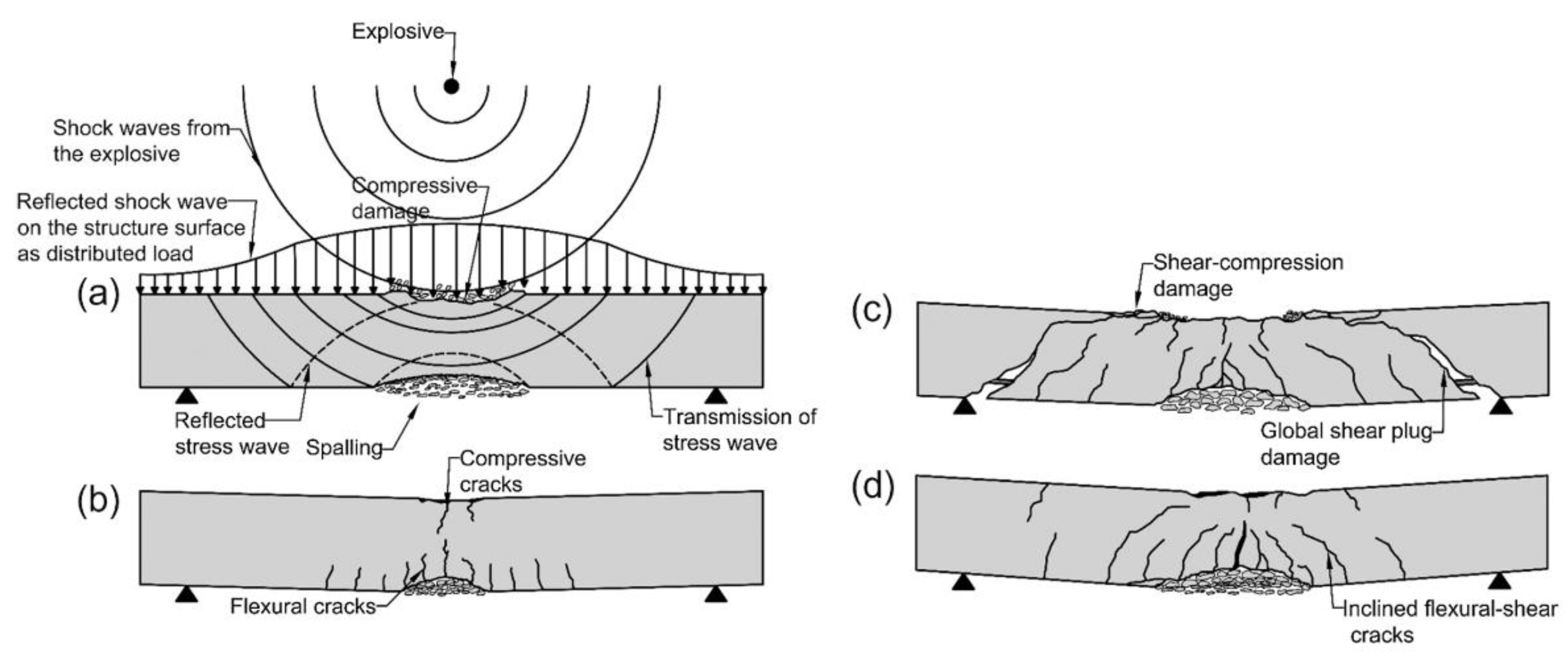
6] evaluated the nonlinear dynamic behaviors and failure modes of simply-supported reinforced concrete beams subjected to the combination of impact and blast loads. After comparison with experimental results and numerical simulations, the damage mode of RC beams under blast loading was concluded to be: local response, global flexural failure, global shear failure and global flexural-shear failure. Compared with the damage characteristics shown in
Figure 1, the failure mode of PSBG is determined by damage coefficient and damage distribution in this work.
Shiravand and Parvanehro [
7] studied the behavior of a typical concrete cantilever bridge under close-in deck explosion and provided the distribution of damage zone. Therefore, it was necessary to apply some energy absorbing or properly fused systems to reduce the close-in deck explosion effects. Lee and Choi et al. [
8] suggested a procedure to assess structural blast-resistance performance based on a numerical analysis approach.
There are several strengthening measures available to improve the working performance of concrete beams in response to their decreased operational state [
9,
10,
11]. However, there is a lack of relevant research on the failure mechanism and preventive strengthening of preventive small box beams under car explosion. In this article, the existing PSBG which widely used in highway bridges and urban viaducts are studied. The thickness of the bridge deck, reinforcement ratio and the strengthening steel plate meet the requirements of the existing design specifications [
12,
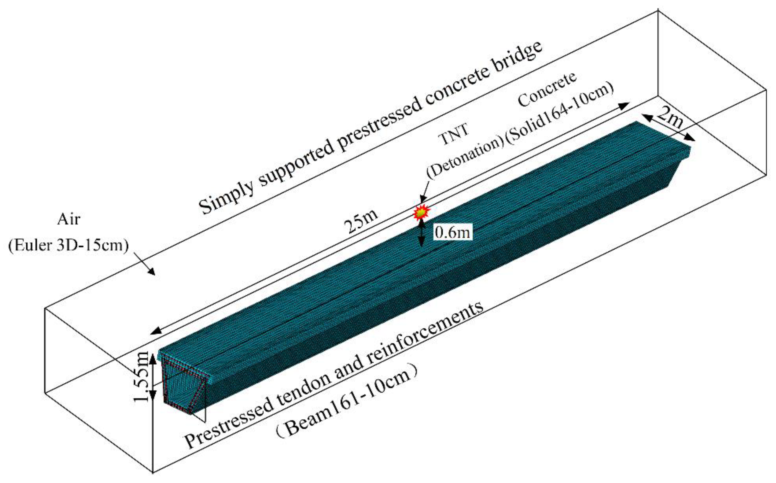
13]. According to existing cars, the fuel tank capacity and gasoline density are 70 L and 0.72kg/L respectively. Therefore, the internal energy of gasoline is similar to TNT.As a result, the 50kg TNT equivalent is proposed to present car explosion in the state of full oil-tank. Due to small lifting weight and convenient construction, simply supported beam becomes competitive in accelerated bridge construction (ABC). Under high pressure shock wave induced by explosive energy, more serious damage even bridge collapse is recognized when explosion happens in mid-span. To analyze the antiknock performance of multi-box girders bridge, the 50 kg TNT equivalent of the car explosion is placed above the top deck in the mid-span. The results of this study are of great significance for the failure mechanism and preventive strengthening of prefabricated box girder under car explosion.
2. Material Constitutive and Finite Element Modeling
2.1. Material Constitutive
Explosion induced energy usually release instantly and tremendously, resulting in high-strain rate [
14] and high temperature field [
7] of structures. The results of impact test showed concrete strength hardening under high-strain rate loading such as vehicle collision and blast loads [
15]. Besides that, it was considered that the characteristic of concrete softening under high temperature could not be ignored in blast analysis. To accurately describe the distribution of stress and failure mode of structures under blast loads, the Riedel-Hiermaier-Thoma (RHT) model is adopted [
16]. Material parameters are shown in
Table 1.
The dynamic constitution of steel has become the main factor to control the accuracy of structural impact analysis. The results of experiment and numerical analysis verify the validity of Johnson-Cook (JC) model in simulating the strain rate sensitivity and the thermal softening of steel [
17]. The flow stress is calculated by equation 1, while
and
stand for the effective plastic strain and normalized effective plastic strain rate respectively.
where
A,
B,
C,
n and
m represent initial yield stress, hardening constant, hardening exponent, strain rate constant and thermal softening exponent respectively [
18] as shown in
Table 2.
The ideal air is presented to simulate air pressure as shown in equation 2:
where
represents a standard atmosphere pressure at the initiation of the explosion,
is the adiabatic index of ideal air, and
is the material density, as shown in
Table 3.
In order to obtain a precise analysis of the interaction between explosive pressure and energy, Jone-Wilkins-Lee (JWL) state equation is adopted here. The JWL equation is as follows:
where
stands for the pressure under blast loads,
is the volume ratio,
is the internal energy, and
A,
B,
R1,
R2, and
are material parameters, values of which are indicated in
Table 4.
3.2. Numerical Model
Due to the high insecurity of anti-explosion test [
19,
20,
21,
22], numerical analysis method becomes an effective way to analyze the damage of structure under blast loads [
23,
24,
25,
26,
27,
28,
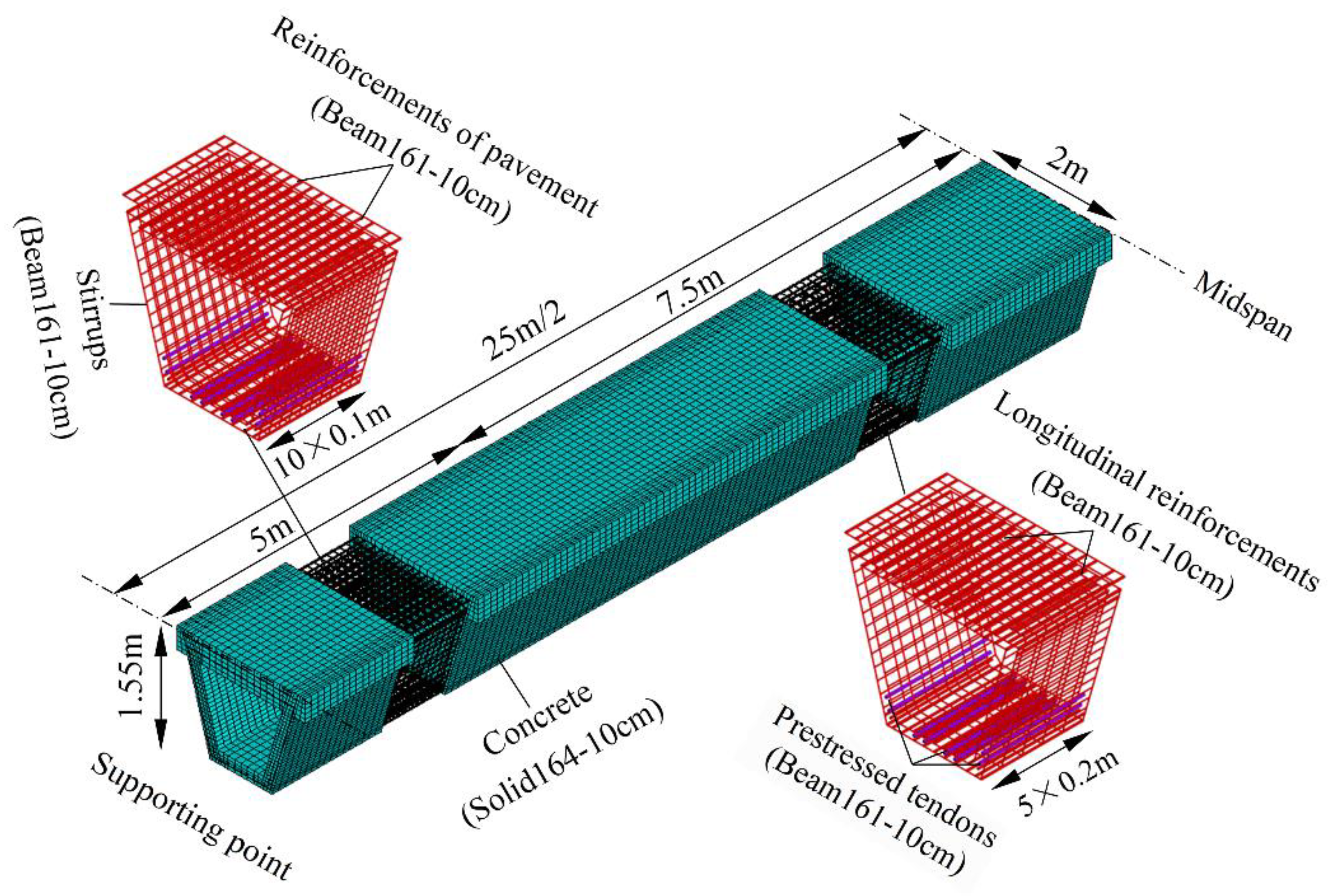
29]. This paper presents a 25 m prefabricated small box girder with simply supported condition and the antiknock performance is studied. The height of the beam is 155 cm, including 140 cm for box girder and 15 cm for deck pavement. In order to accurately reflect the dynamic response and damage distribution under explosion, the arrangement of steel bars is consistent with the design drawings. The longitudinal steel bars adopt a diameter of 22 mm with a reinforcement ratio of 1.37%. To avoid shear failure under design loads, the diameter of stirrups is selected to be 12mm with a spacing of 10 cm around supporting point in 5 m. Except for large shear zone, the spacing of stirrups is determined to be 20 cm. Beam 161 is presented to simulate the reinforcements with rigid body rotation and finite strains during blast loads. To ensure the bonding property between reinforcements and concrete, sheared nodes are adopted. Besides that, transverse and longitudinal reinforcements are interconnected to stand for steel skeleton. An ideal non-slip connection is established between prestressed tendons and concrete. The initial prestress of prestressed tendon is 1395MPa with equivalent strain. Self-weight is considered with the gravitational acceleration of 9.8 m/s
2. Convergence studies conducted by Pan et al. [
30] showed that a 10 cm mesh size was adequate to ensure a reliable pressure time-history and dynamic structural response compared with the experimental data. Further, the air mesh size and explosive mesh size were suggested to be 10 cm in this work. In order to balance the calculation accuracy and the arrangements of steel bars, the element size of 10 cm is adopted in this study as shown in
Figure 2.
High pressure and temperature field were commonly observed during blast wave. Due to the difference in energy transmission and thermal conductivity, the interface between air and structure behaves the characteristic of fluid-solid coupling. The establishment of the air domain and the selection of air pressure are crucial to the accuracy of the calculation results. In order to accurately reflect the blast wave propagation and structural response, the air region is set to 27m×3m×3m to completely wrap the analyzed model as shown in
Figure 3.
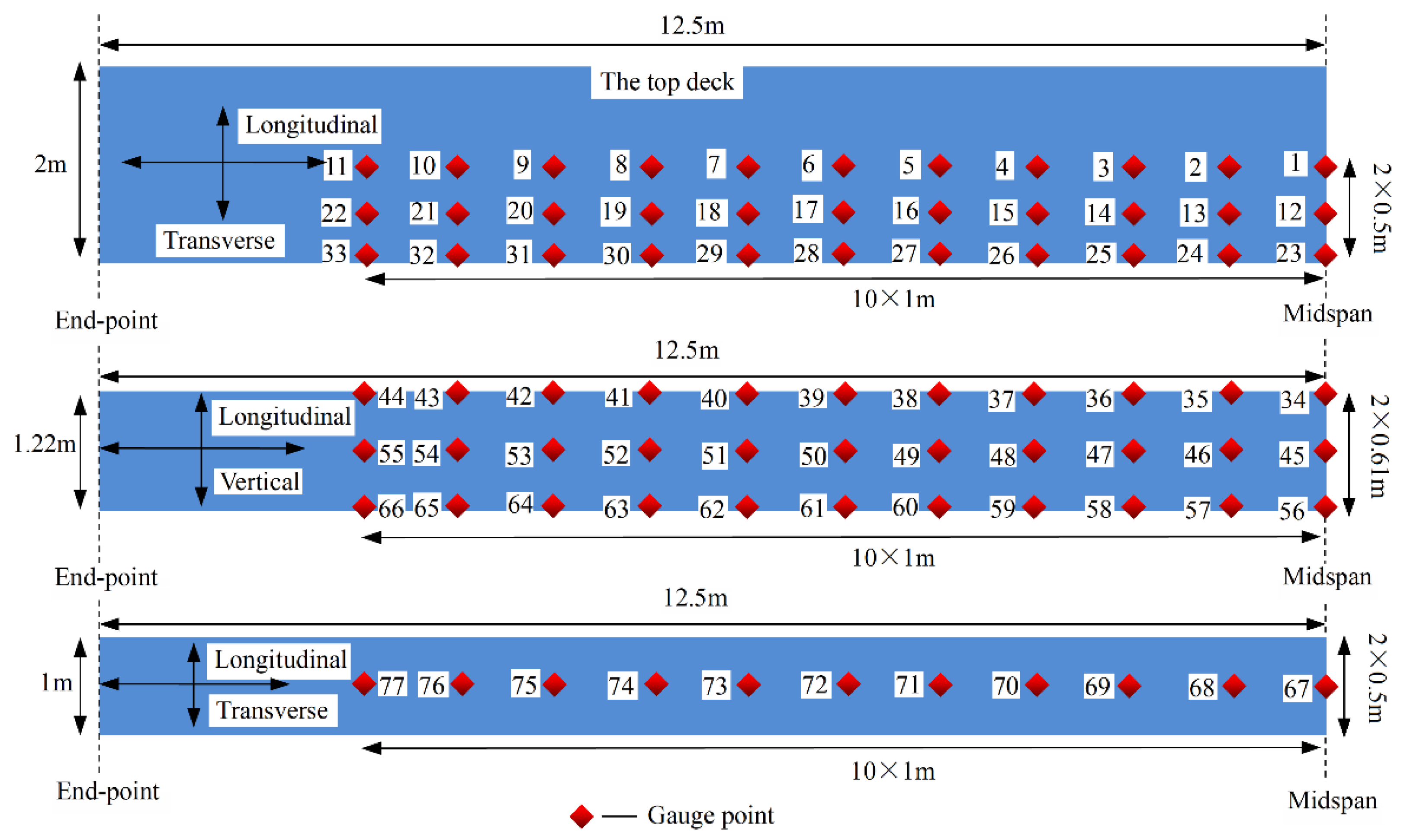
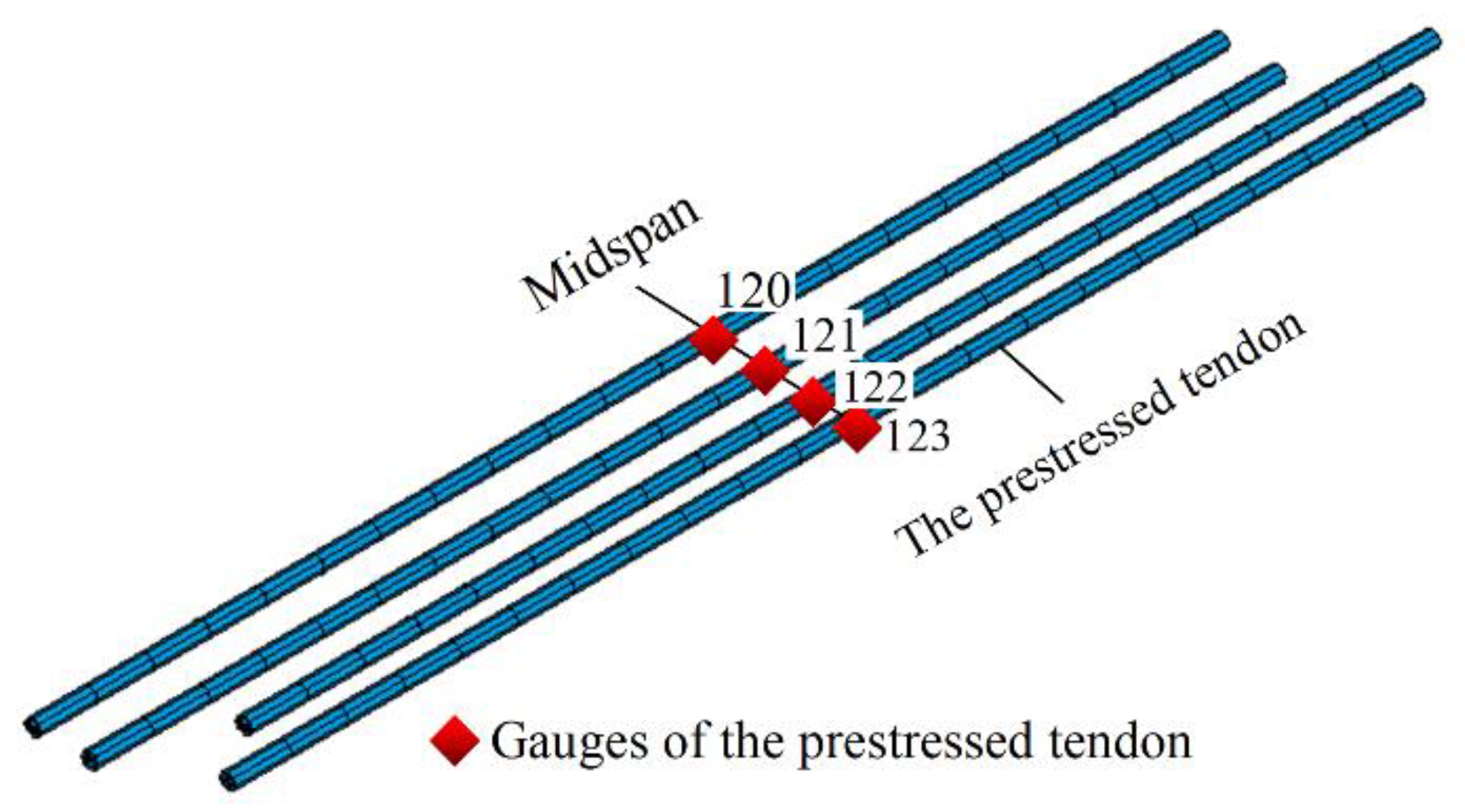
In order to obtain the distribution and pressure-time history of the blast wave on the structure, as well as the local response and global damage mode of the beam, gauges are located as shown in
Figure 4,
Figure 5 and
Figure 6.
3. Bridge Performance and Result Discussion
3.1. Failure Mode of PSBG
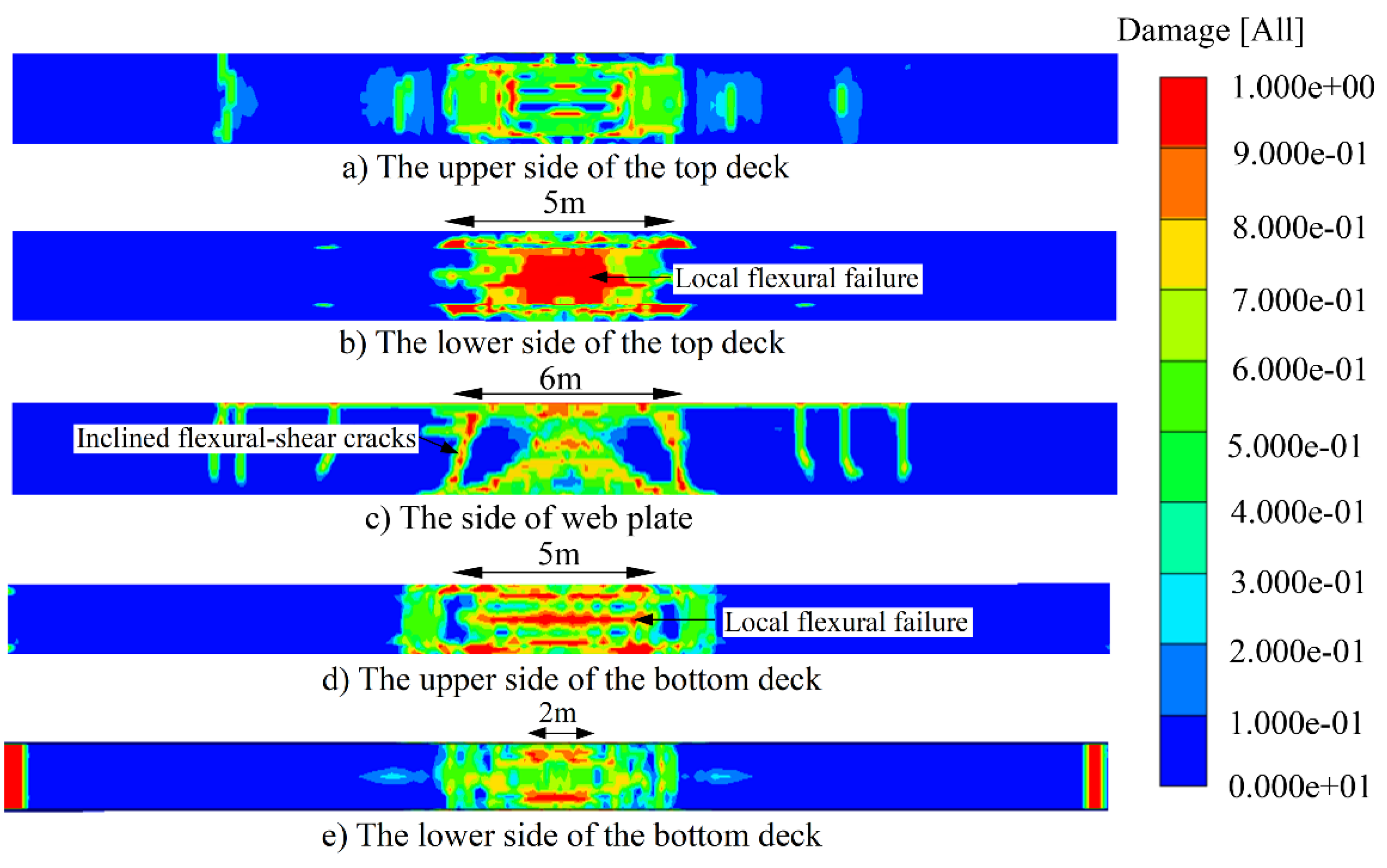
To quantificationally describe the failure mode of PSBG after car explosion, the damage coefficient is presented. With the damage coefficient from 0 to 1, the concrete damage goes from no damage to total failure. Furthermore, the failure mode could be defined by damage coefficient and damage distribution. According to
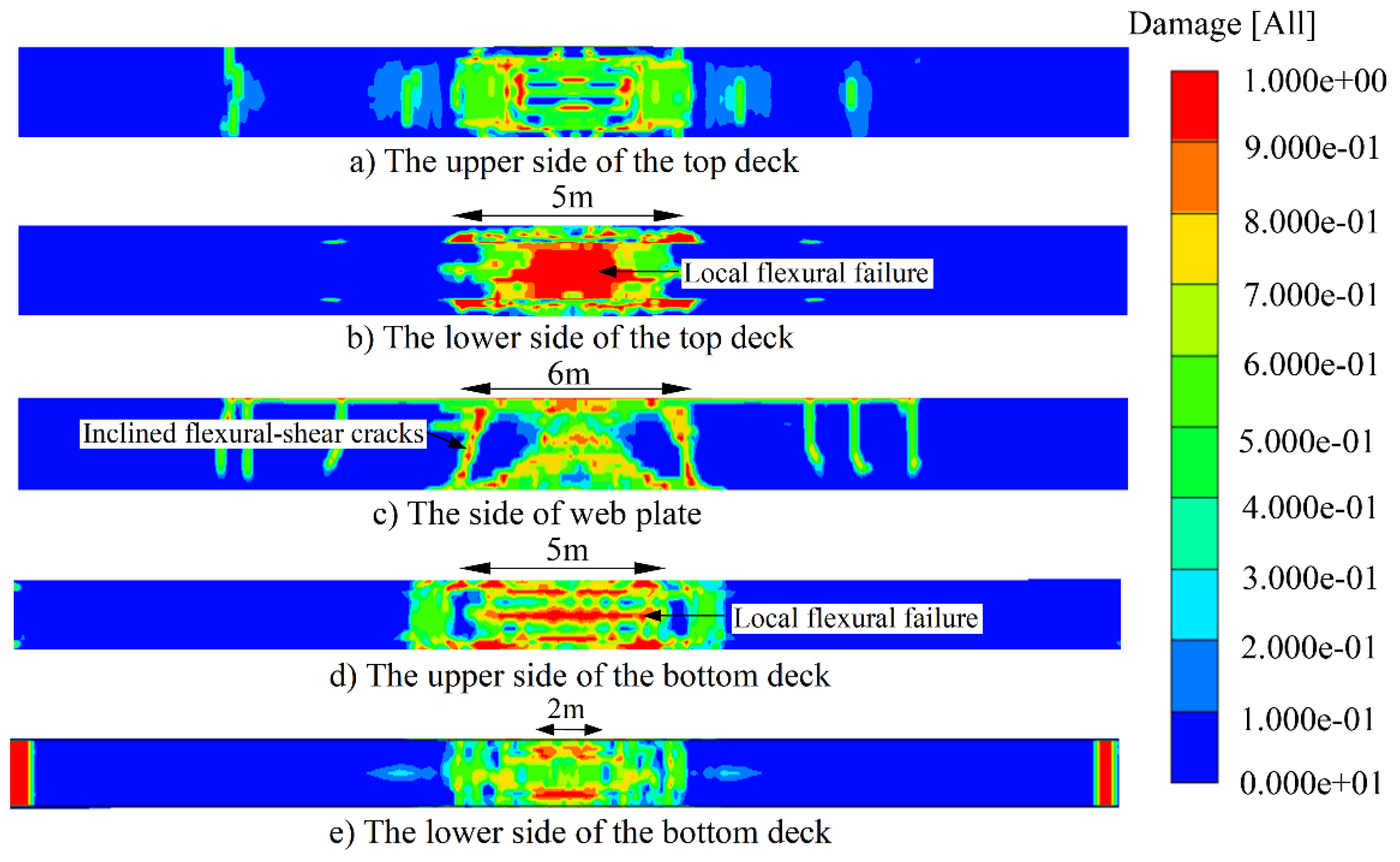
Figure 7, the damage mode of PSBG consists of local flexural failure and global flexural-shear failure under car explosion. The overall flexural-shear failure mode of the structure is basically consistent with
Figure 1d, because of the inclined flexural-shear cracks and the distribution of damage zone as shown in
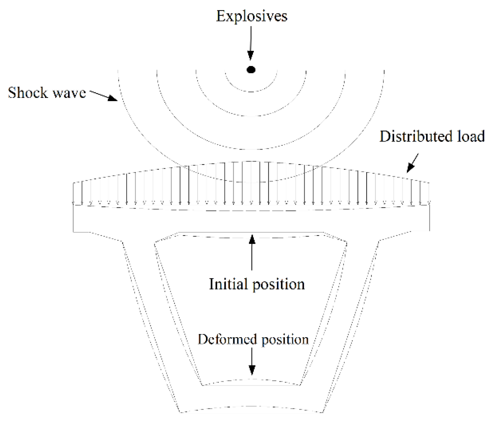
Figure 7c. However, due to the framing effect in transverse direction as shown in
Figure 8, the tensile zone appears in the lower side of the top deck and the upper side of the bottom deck respectively as shown in
Figure 7a,b,d,e. Finally, brittle flexural-shear failure occurs and the bearing capacity is lost.
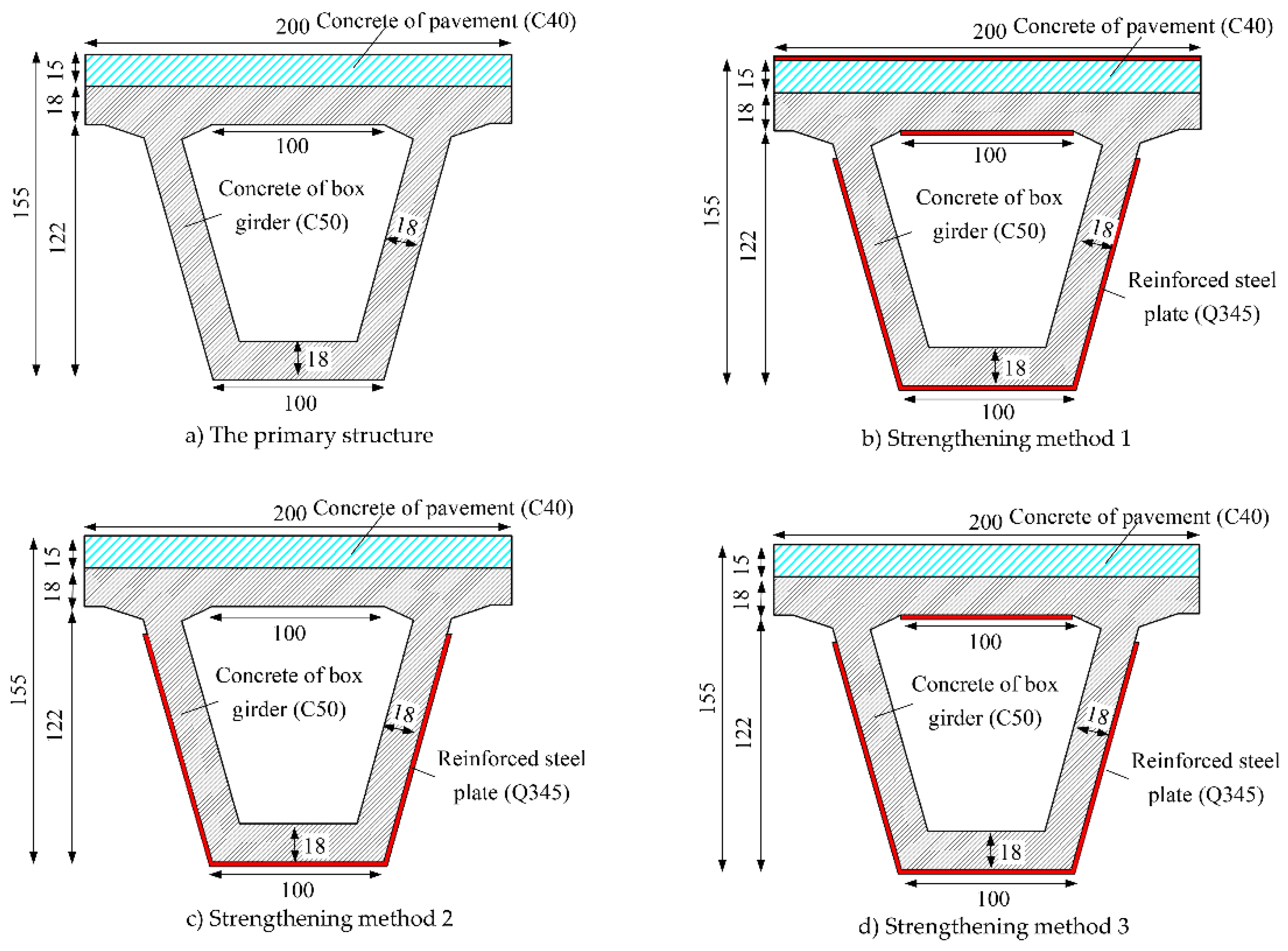
According to the damage model of the structure under car explosion, preventive strengthening methods are proposed to avoid the sudden collapse of the structure as shown in
Figure 9. Strengthening method 1 is expected to prevent the box girder from global flexural-shear failure as depicted in
Figure 9b. Except for global flexural-shear failure, local flexural failure in bridge deck should be mitigated or controlled. As a result, strengthening method 2 is presented to enhance the tensile zone of concrete deck as shown in
Figure 9c. Further, strengthening method 3 is suggested to concern the transformation of tensile area during reciprocating vibration as indicated in
Figure 9d. According to specification for strengthening design [
9], the objective of strengthening is to prevent collapse and prompt post-disaster rehabilitation. To balance the construction difficulty and reinforcement effect, the 8mm thick steel plate is adopted. Further, epoxy adhesives and anchor bolts are utilized to avoid slippage and spalling of steel plates. While the adhesive performance and anchor arrangements meet the requirements, node connections can be used between concrete and steel plates.
3.2. Failure Mode of Strengthening Method 1
Sticking the u-shaped steel plate can effectively improve the shear capacity, and the ultimate failure mode of the structure is transformed from flexural-shear failure to flexural failure as shown in Figures 1b and 10c. The U-shaped steel plate improves the shear bearing capacity of the section and reduces the inverted arch of the bottom deck caused by shear deformation. The local failure mode of the bottom deck is controlled by the overall bending failure, which shows that the lower edge of the bottom deck presents more serious failure than the upper edge as shown in
Figure 10d,e. The local bending failure of the top deck has not been effectively improved, and the compression area of the section is seriously damaged, which eventually leads to the loss of bending capacity of the structure as shown in
Figure 10a–c.
3.3. Failure Mode of Strengthening Method 2
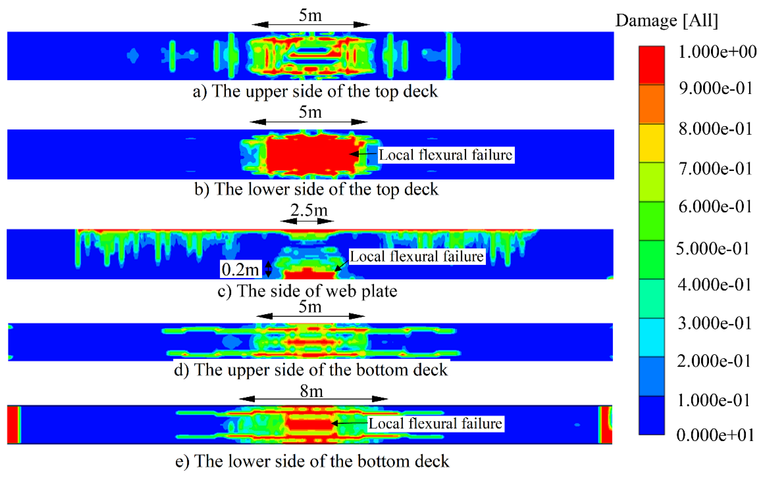
In order to enhance the performance of the compressive zone, improve the overall bending resistance of the section, and avoid the bending damage of the structure, the scheme of sticking the steel plate on the lower edge of the top deck is proposed as shown in
Figure 9c. Strengthening method 2 can effectively improve the overall bending performance of the structure, and the bending failure height of the structure is reduced to 20 cm as shown in
Figure 11c.
Figure 11d,e shows that the failure of tensile zone increases corresponding to the failure delay in compression zone, which provide the flexural capacity cooperatively. As the lower edge of the top deck can adapt to greater impact deformation after sticking steel plate, the damaged area of concrete increases, but the overall compressive performance improves as shown in
Figure 11a–c.
3.4. Failure Mode of Strengthening Method 3
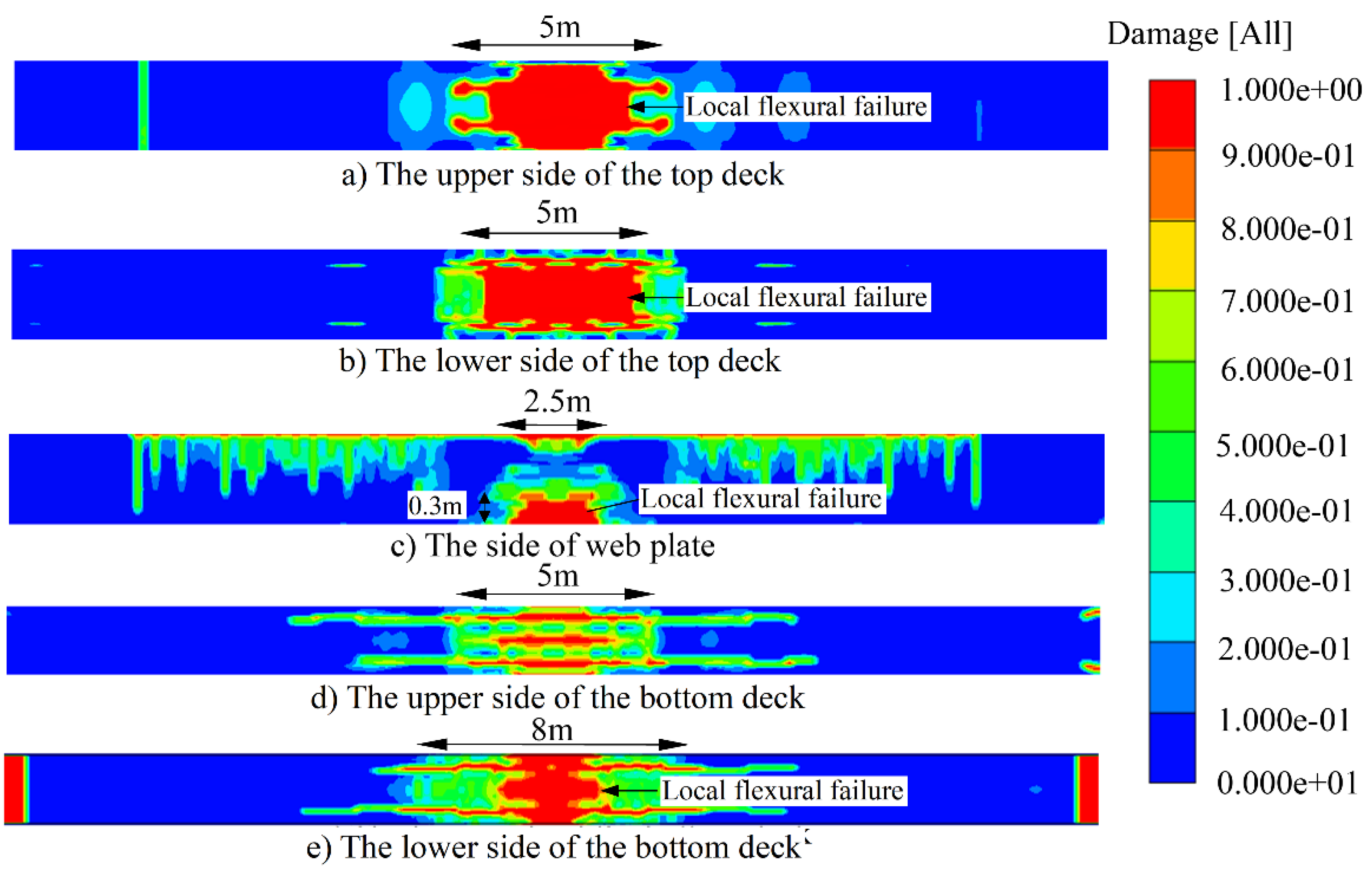
Compared with strengthening method 2, strengthening method 3 does not effectively improve the overall flexural performance of the structure and reduce the degree of structural failure under car explosion as shown in
Figure 12. As the top surface enhancing with steel plate, the impact energy is concentrated, and the final bending failure height of the structure is increased by 10 cm compared with the reinforced scheme 2. Considering the impact response and strengthening economy of the structure, strengthening method 3 is not recommended.
4. Discussion of the Failure Mechanism
Due to the instantaneous release of explosive impact energy, the final failure state of the structure was analyzed above. However, during the failure process of the structure, the pressure distribution pattern and the impact failure characteristics of the structure are of great significance.
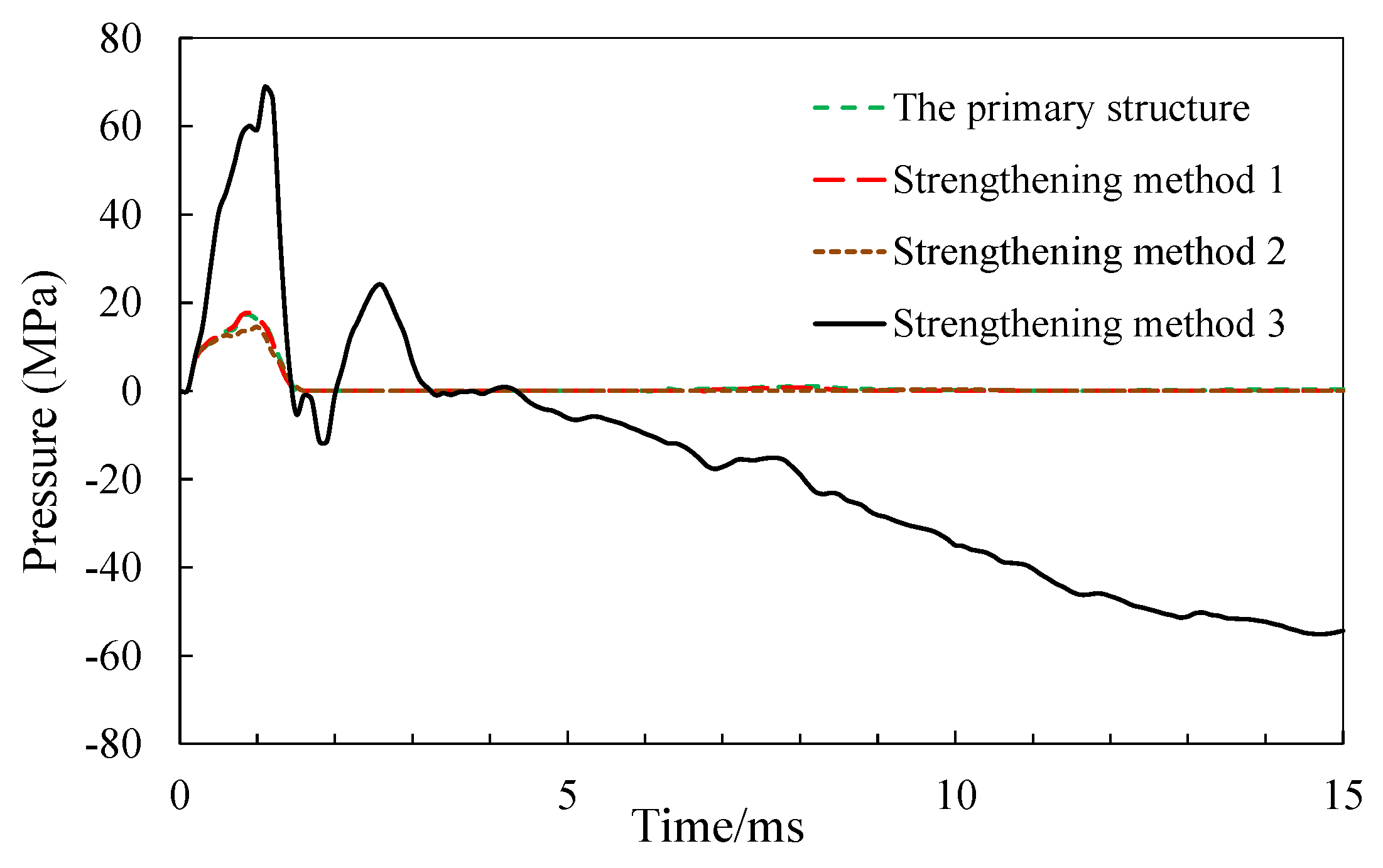
Figure 13 indicates the impact energy dissipates in about 2 ms,except the strengthening method 3 because of energy concentration.
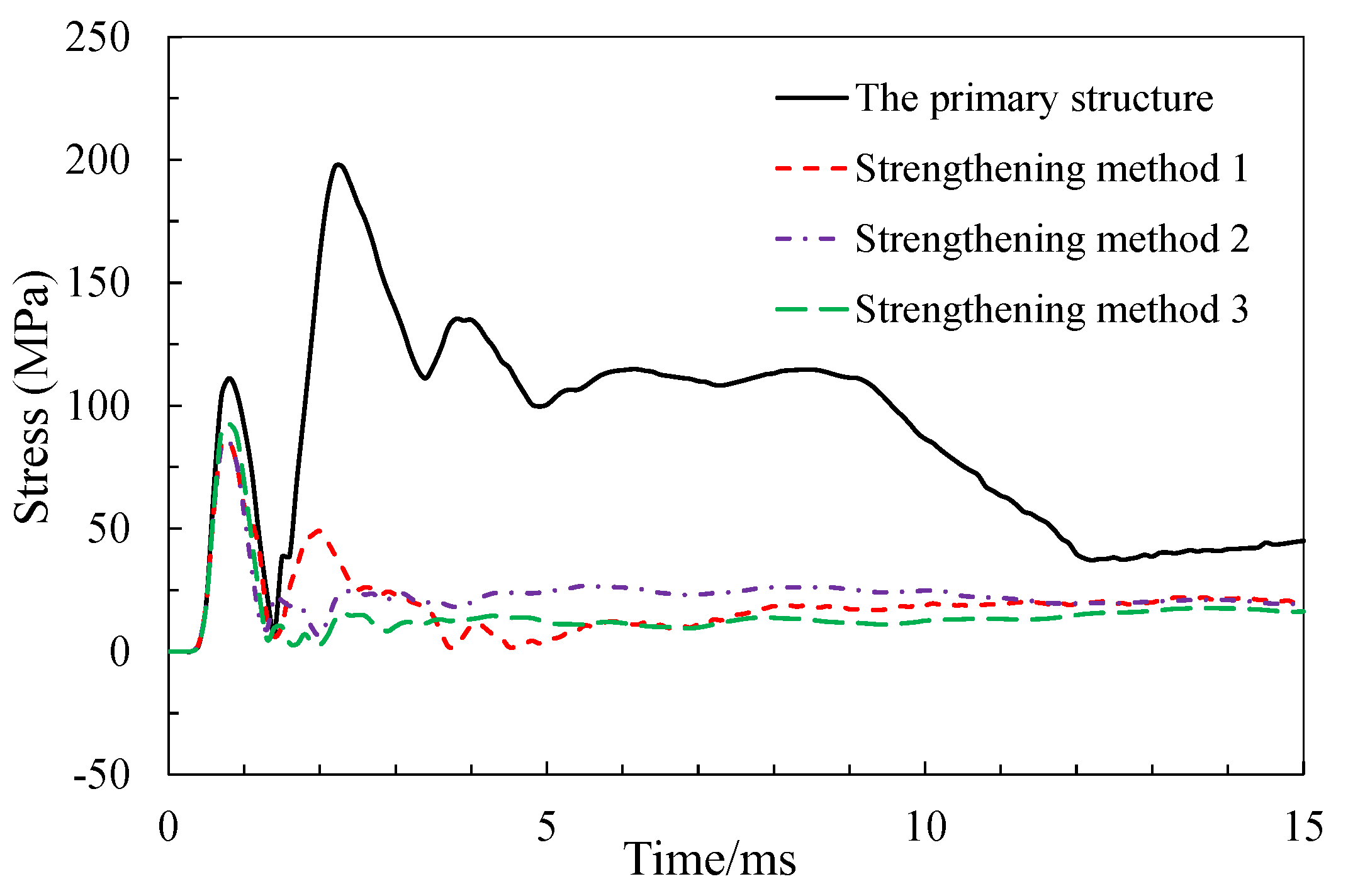
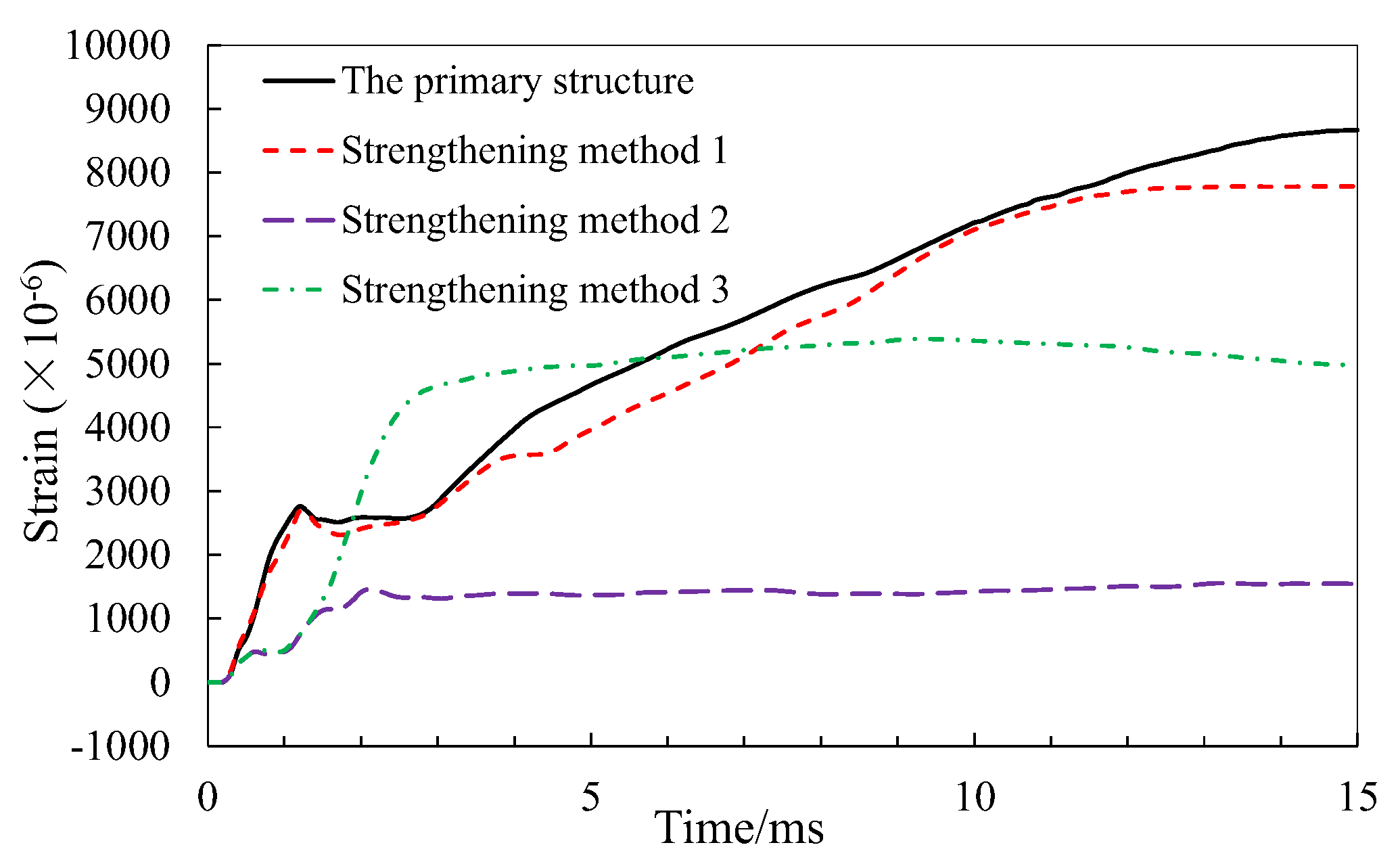
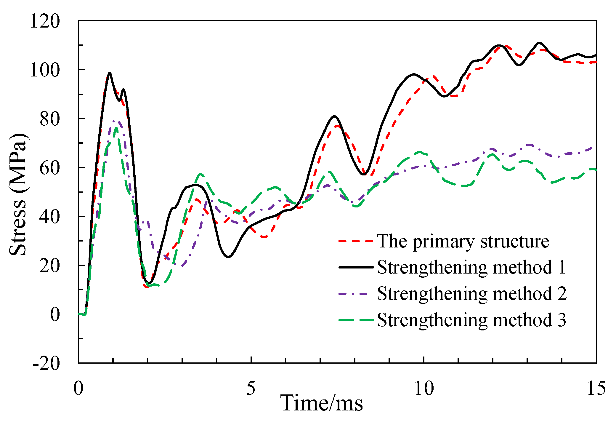
Sticking U-shaped steel plate can effectively reduce the stress of web concrete and stirrups. The shear strain of concrete is reduced from 2000 to 500, and the shear stress of stirrup is reduced from 200MPa to 118MPa as shown in
Figure 14 and
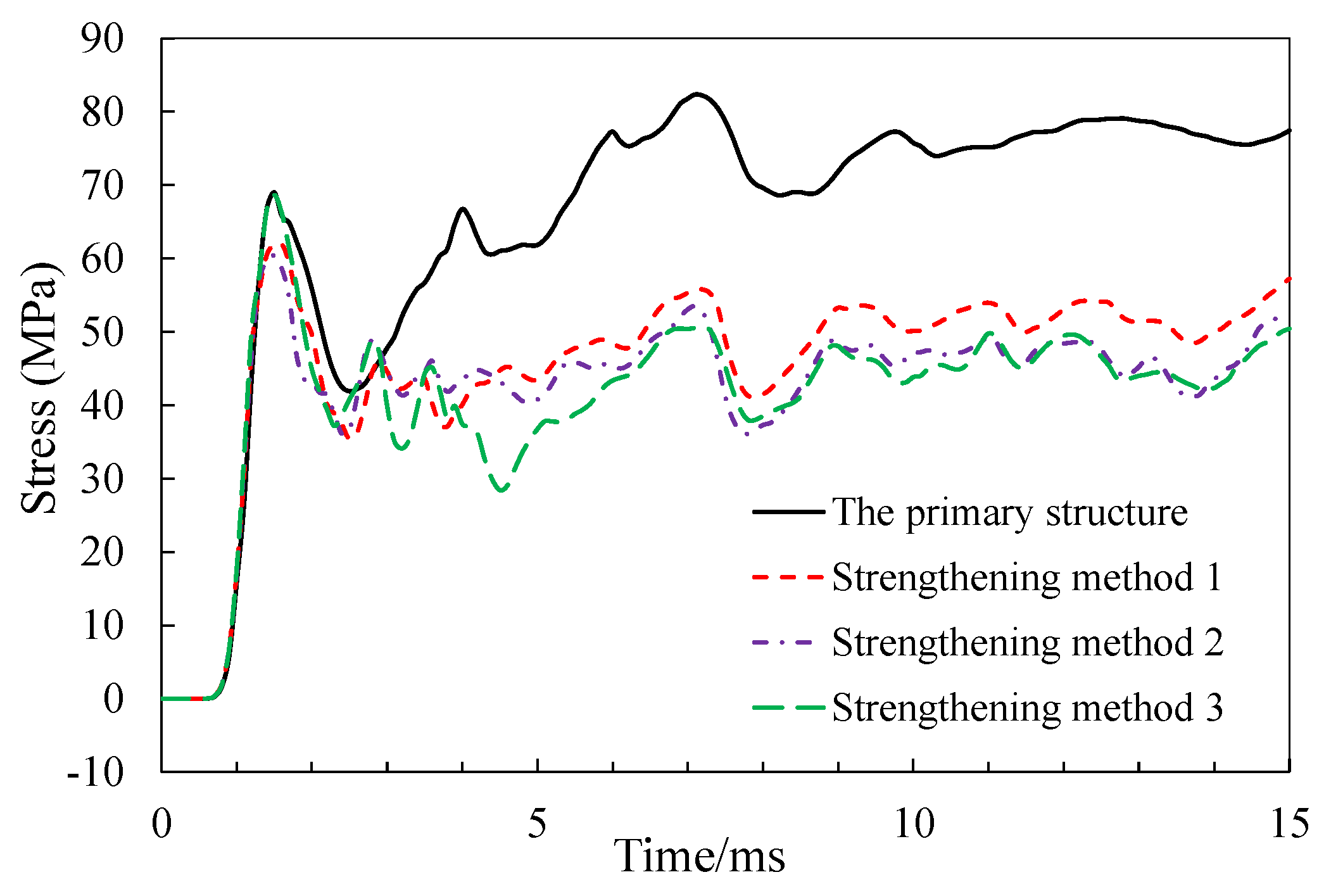
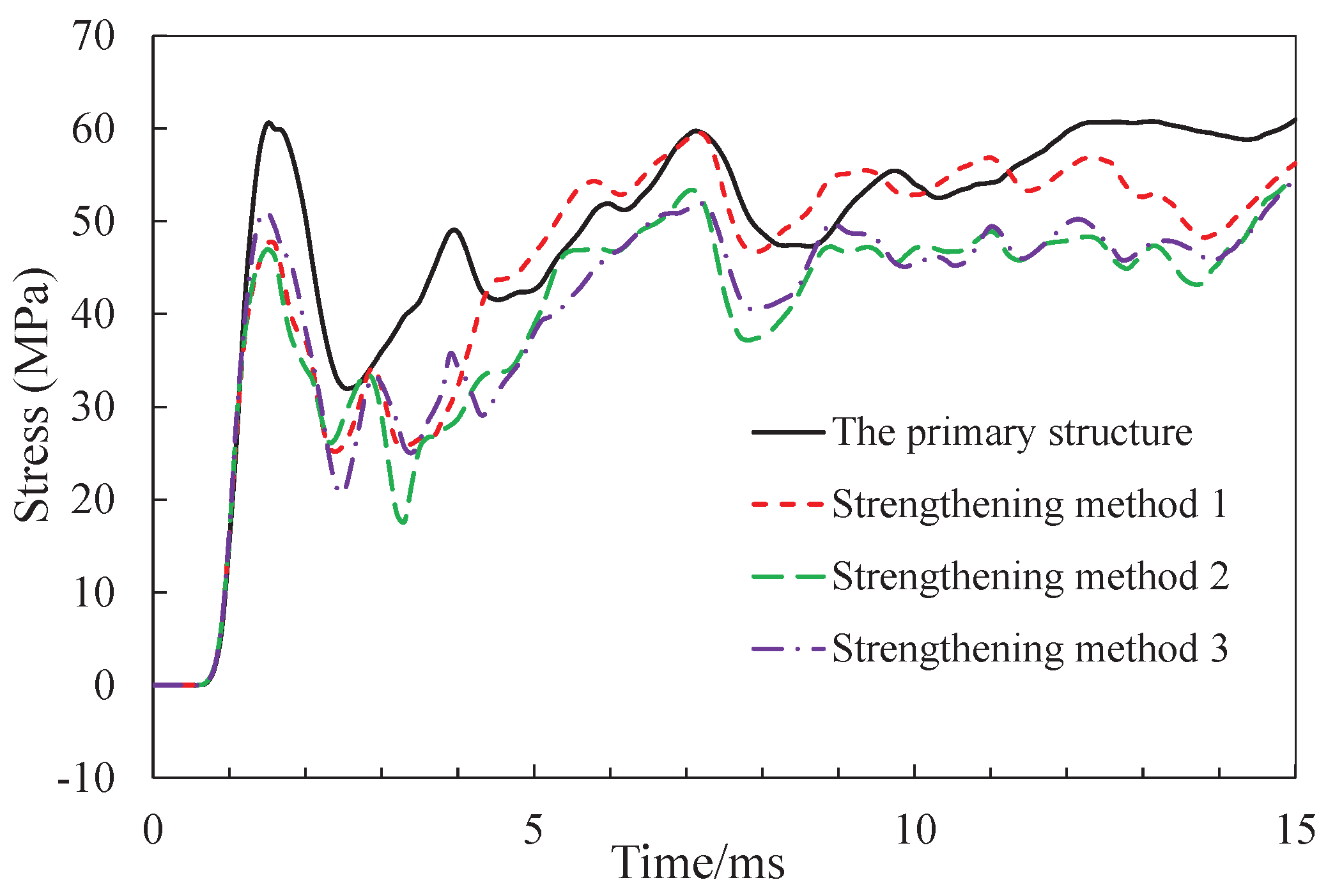
Figure 15. The U-shaped steel plate can effectively reduce the tensile stress of the longitudinal steel bar in the lower of the bottom deck, and the reduction range is about 11MPa as shown in
Figure 16.
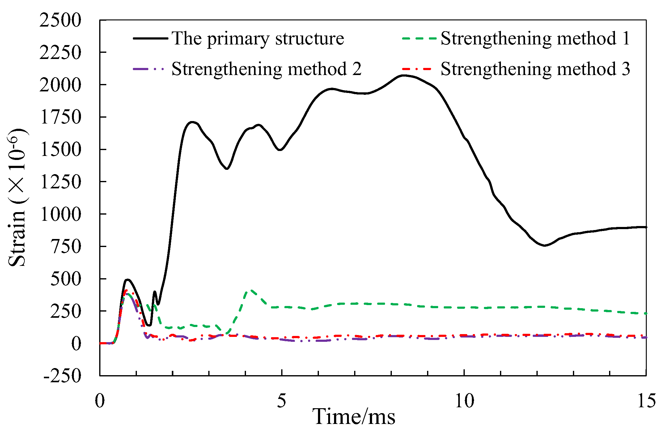
Sticking steel plate on the lower edge of the top deck can effectively reduce the compressive strain in the compression and reduce the damage of the concrete under blast loads as shown in
Figure 17. Compared with the strengthening method 2, the concrete strain in the compression zone of the strengthening method 3 is larger, as a result of the impact of explosive energy concentration.
Figure 18 shows that strengthening structure with bonded steel plate in the lower side of the top deck can improve the tensile stress of steel bars in the top deck, promote a better performance under car explosion. In the process of explosion analysis, the stress increment of prestressed tendon is small, and it will not yield or fracture as shown in
Figure 19.
5. Conclusions
The purpose of this work is to investigate the failure mechanism and preventive strengthening methods of prefabricated small box girder under car explosion. The structural design of analyzed box girder is in line with the current design specification of RC and PC structures. The 50kg TNT equivalent is placed 0.6 m above bridge deck represent a car explosion in the state of full oil-tank. After verification by previous studies, three strengthening methods are put forward to improve the performance of precast box girder under car explosion. Further, the antiknock performances of these strengthening methods are discussed. After cautious simulation, the following results can be drawn:
- (1)
After verification by previous studies, the damage mode of PSBG consists of global flexural-shear failure and local flexural failure under car explosion. To avoid excessive deformation even bridge collapse after car explosion, it is the key to enhance the flexural-shear capacity of the section and the local flexural capacity of the bridge deck. According to the damage mode, U-shape steel plate and flat steel plate are proposed to enhance the global flexural-shear capacity and bending capacity of bridge deck respectively.
- (2)
Compared with the primary structure, the three strengthening methods can effectively improve the anti-explosion performance of box girder under car explosion. After strengthening with the U-shaped steel plate, the structural failure modes change from global flexural-shear failure to global flexural failure. Adhering steel plate in the lower edge of the top deck can improve the bending capacity of the top deck, reducing the failure in compression zone and strengthening the global flexural resistance. While the steel plate attached to the upper edge of the top deck, the local impact vibration and the bending capacity is strengthened concurrently. As a result, the damage mode is not obviously improved.
- (3)
Strengthening method 2 is the most effective way to improve the anti-explosion performance of prefabricated small box girder bridges, reducing structural failure, maintaining bearing capacity, avoiding bridge collapse, and buying time for subsequent rescue and maintenance.
Author Contributions
Methodology, WL.H.; software, ZN.Y.; validation, ZN.Y.; formal analysis, ZN.Y.; data curation, FH.D.; supervision, WL.H.; funding acquisition, FH.D. All authors have read and agreed to the published version of the manuscript.
Funding
The Natural Science Foundation of Jiangsu Province (Grant No. BK20200793).
Data Availability Statement
Data is contained within the article.
Conflicts of Interest
The authors declare no conflict of interest.
References
- Draganić, H.; Gazić, G.; Varevac, D. Experimental Investigation of Design and Retrofit Methods for Blast Load Mitigation – A State-of-the-Art Review. Engineering Structures 2019, 190, 189–209. [Google Scholar] [CrossRef]
- Wang, W.; Liu, R.; Wu, B. Analysis of a Bridge Collapsed by an Accidental Blast Loads. Engineering Failure Analysis 2014, 36, 353–361. [Google Scholar] [CrossRef]
- Zhai, C.; Chen, L.; Xiang, H.; Fang, Q. Experimental and Numerical Investigation into RC Beams Subjected to Blast after Exposure to Fire. International Journal of Impact Engineering 2016, 97, 29–45. [Google Scholar] [CrossRef]
- Zhu, Z.; Li, Y.; He, S.; Ma, C. Analysis of the Failure Mechanism of Multi-Beam Steel–Concrete Composite Bridge under Car Explosion. Advances in Structural Engineering 2020, 23, 538–548. [Google Scholar] [CrossRef]
- Hu, Z.; Zhang, Y.; Yu, W.; Mao, S.; Fang, J. Anti-Blast Resistance Analysis of Prestressed Concrete Bridges under Close-by Blast. China Journal of Highway and Transport 2019, 32, 71–80. [Google Scholar]
- Zhang, C.; Gholipour, G.; Mousavi, A.A. Nonlinear Dynamic Behavior of Simply-Supported RC Beams Subjected to Combined Impact-Blast Loading. Engineering Structures 2019, 181, 124–142. [Google Scholar] [CrossRef]
- Shiravand, M.R.; Parvanehro, P. Numerical Study on Damage Mechanism of Post-Tensioned Concrete Box Bridges under Close-in Deck Explosion. Engineering Failure Analysis 2017, 81, 103–116. [Google Scholar] [CrossRef]
- Lee, J.; Choi, K.; Chung, C. Numerical Analysis-Based Blast Resistance Performance Assessment of Cable-Stayed Bridge Components Subjected to Blast Loads. Applied Sciences 2020, 10, 8511. [Google Scholar] [CrossRef]
- Schmidt, J.W.; Sørensen, J.D.; Christensen, C.O. In Situ Concrete Bridge Strengthening Using Ductile Activated NSMR CFRP System. Buildings 2022, 12, 2244. [Google Scholar] [CrossRef]
- Kim, S.-H.; Park, J.-S.; Jung, W.-T.; Kim, T.-K.; Park, H.-B. Experimental Study on Strengthening Effect Analysis of a Deteriorated Bridge Using External Prestressing Method. Applied Sciences 2021, 11, 2478. [Google Scholar] [CrossRef]
- Kim, S.-H.; Park, J.-S.; Jung, W.-T.; Kang, J.-Y. Strengthening Effect of the External Prestressing Method That Simulated a Deterioration Bridge. Applied Sciences 2021, 11, 2553. [Google Scholar] [CrossRef]
- MOT, (Ministry of Transportation) Code for Design of Highway Reinforced Concrete and Prestressed Concrete Bridges and Culverts. [In Chinese.] JTG D62-2004. Beijing. 2004.
- MOT, (Ministry of Transportation) Specifications for Strengthening Design of Highway Bridges. [In Chinese.] JTG/T J22-2008. Beijing. 2008.
- Forni, D.; Chiaia, B.; Cadoni, E. Blast Effects on Steel Columns under Fire Conditions. Journal of Constructional Steel Research 2017, 136, 1–10. [Google Scholar] [CrossRef]
- Thomas, R.J.; Steel, K.; Sorensen, A.D. Reliability Analysis of Circular Reinforced Concrete Columns Subject to Sequential Vehicular Impact and Blast Loading. Engineering Structures 2018, 168, 838–851. [Google Scholar] [CrossRef]
- Tu, Z.; Lu, Y. Modifications of RHT Material Model for Improved Numerical Simulation of Dynamic Response of Concrete. International Journal of Impact Engineering 2010, 37, 1072–1082. [Google Scholar] [CrossRef]
- Forni, D.; Chiaia, B.; Cadoni, E. Strain Rate Behaviour in Tension of S355 Steel: Base for Progressive Collapse Analysis. Engineering Structures 2016, 119, 164–173. [Google Scholar] [CrossRef]
- Hashemi, S.K.; Bradford, M.A.; Valipour, H.R. Dynamic Response and Performance of Cable-Stayed Bridges under Blast Load: Effects of Pylon Geometry. Engineering Structures 2017, 137, 50–66. [Google Scholar] [CrossRef]
- Williamson, E.B.; Bayrak, O.; Davis, C.; Williams, G.D. Performance of Bridge Columns Subjected to Blast Loads. I: Experimental Program. J. Bridge Eng. 2011, 16, 693–702. [Google Scholar] [CrossRef]
- Kyei, C.; Braimah, A. Effects of Transverse Reinforcement Spacing on the Response of Reinforced Concrete Columns Subjected to Blast Loading. Engineering Structures 2017, 142, 148–164. [Google Scholar] [CrossRef]
- Yan, B.; Liu, F.; Song, D.; Jiang, Z. Numerical Study on Damage Mechanism of RC Beams under Close-in Blast Loading. Engineering Failure Analysis 2015, 51, 9–19. [Google Scholar] [CrossRef]
- Li, J.; Wu, C.; Hao, H.; Su, Y. Experimental and Numerical Study on Steel Wire Mesh Reinforced Concrete Slab under Contact Explosion. Materials & Design 2017, 116, 77–91. [Google Scholar] [CrossRef]
- Liu, J.; Yin, Y.; Zhao, Y.; Li, Y. Dynamic Behavior Analysis of I-Shaped RC Beams under Combined Blast and Impact Loads. Applied Sciences 2023, 13, 1943. [Google Scholar] [CrossRef]
- Hao, H.; Tang, E.K.C. Numerical Simulation of a Cable-Stayed Bridge Response to Blast Loads, Part II: Damage Prediction and FRP Strengthening. Engineering Structures 2010, 32, 3193–3205. [Google Scholar] [CrossRef]
- Son, J.; Lee, H.-J. Performance of Cable-Stayed Bridge Pylons Subjected to Blast Loading. Engineering Structures 2011, 33, 1133–1148. [Google Scholar] [CrossRef]
- Tang, E.K.C.; Hao, H. Numerical Simulation of a Cable-Stayed Bridge Response to Blast Loads, Part I: Model Development and Response Calculations. Engineering Structures 2010, 32, 3180–3192. [Google Scholar] [CrossRef]
- Yao, S.; Zhang, D.; Lu, F.; Wang, W.; Chen, X. Damage Features and Dynamic Response of RC Beams under Blast. Engineering Failure Analysis 2016, 62, 103–111. [Google Scholar] [CrossRef]
- Andreou, M.; Kotsoglou, A.; Pantazopoulou, S. Modelling Blast Effects on a Reinforced Concrete Bridge. Advances in Civil Engineering 2016, 2016, 1–11. [Google Scholar] [CrossRef]
- Carta, G.; Stochino, F. Theoretical Models to Predict the Flexural Failure of Reinforced Concrete Beams under Blast Loads. Engineering Structures 2013, 49, 306–315. [Google Scholar] [CrossRef]
- Pan, Y.; Chan, B.Y.B.; Cheung, M.M.S. Blast Loading Effects on an RC Slab-on-Girder Bridge Superstructure Using the Multi-Euler Domain Method. J. Bridge Eng. 2013, 18, 1152–1163. [Google Scholar] [CrossRef]
Figure 1.
Theoretical response of RC beams subjected to air blast loading: (a) local response; (b) global flexural failure; (c) global shear failure; (d) global flexural-shear failure [
6].
Figure 1.
Theoretical response of RC beams subjected to air blast loading: (a) local response; (b) global flexural failure; (c) global shear failure; (d) global flexural-shear failure [
6].
Figure 2.
Finite element model of prefabricated small box girder.
Figure 2.
Finite element model of prefabricated small box girder.
Figure 3.
Fluid-solid coupling analysis model under explosion.
Figure 3.
Fluid-solid coupling analysis model under explosion.
Figure 4.
Arrangement of defined gauges in concrete.
Figure 4.
Arrangement of defined gauges in concrete.
Figure 5.
Arrangement of defined gauges in steel bars.
Figure 5.
Arrangement of defined gauges in steel bars.
Figure 6.
Arrangement of defined gauges in prestressed tendons.
Figure 6.
Arrangement of defined gauges in prestressed tendons.
Figure 7.
The damage distribution of PSBG under car explosion.
Figure 7.
The damage distribution of PSBG under car explosion.
Figure 8.
The framing effect of box girder under car explosion.
Figure 8.
The framing effect of box girder under car explosion.
Figure 9.
The section of the analytical model (unit: cm).
Figure 9.
The section of the analytical model (unit: cm).
Figure 10.
The damage mode of strengthening method 1 after explosion.
Figure 10.
The damage mode of strengthening method 1 after explosion.
Figure 11.
The damage mode of strengthening method 2 after explosion.
Figure 11.
The damage mode of strengthening method 2 after explosion.
Figure 12.
The damage mode of strengthening method 3 after explosion.
Figure 12.
The damage mode of strengthening method 3 after explosion.
Figure 13.
Pressure history of gauge 1.
Figure 13.
Pressure history of gauge 1.
Figure 14.
Shear strain-time history of concrete in the web plate (gauge 47).
Figure 14.
Shear strain-time history of concrete in the web plate (gauge 47).
Figure 15.
Stress-time history of stirrups in middle of the web plate (gauge 111).
Figure 15.
Stress-time history of stirrups in middle of the web plate (gauge 111).
Figure 16.
Stress-time history of steel bar in lower of the bottom deck (gauge 117).
Figure 16.
Stress-time history of steel bar in lower of the bottom deck (gauge 117).
Figure 17.
Strain-time history of concrete in the compressive zone (gauge 1).
Figure 17.
Strain-time history of concrete in the compressive zone (gauge 1).
Figure 18.
Stress-time history of steel bar in lower of the top deck (gauge 78).
Figure 18.
Stress-time history of steel bar in lower of the top deck (gauge 78).
Figure 19.
Stress history of prestressed tendon (gauge 120).
Figure 19.
Stress history of prestressed tendon (gauge 120).
Table 1.
Material parameters of concrete.
Table 1.
Material parameters of concrete.
| Compressive Strength (fc)(MPa) |
Tensile Strength
(ft/fc) |
Shear Strength
(fs/fc) |
Elastic modulus
(MPa) |
Shear modulus
(MPa) |
| 32.4 |
0.1 |
0.18 |
32500 |
13000 |
Table 2.
Material parameters of JC equation state.
Table 2.
Material parameters of JC equation state.
| Material |
Parameter A
(MPa) |
Parameter B
(MPa) |
Parameter C
|
Parameter n
|
Parameter m
|
| Steel bar |
330 |
405.9 |
0.26 |
0.014 |
1.03 |
| Prestressed tendon |
1860 |
2287.8 |
0.26 |
0.014 |
1.03 |
| Steel plate |
345 |
424.4 |
0.26 |
0.014 |
1.03 |
Table 3.
Material parameters of air.
Table 3.
Material parameters of air.
(g·cm-3) |
(J·kg-1) |
|
| 0.00125 |
2.068×10⁵
|
1.4 |
Table 4.
Material parameters of JWL equation state.
Table 4.
Material parameters of JWL equation state.
| Parameter R1
|
Parameter R2
|
Parameter A (MPa) |
Parameter B (MPa) |
Parameter
|
Density
(g·cm-3) |
V |
E0
(J·kg-1) |
| 4.15 |
0.90 |
3.378×10⁵
|
3.747×10³
|
0.35 |
1.63 |
1.00 |
7.0×10⁶
|
|
Disclaimer/Publisher’s Note: The statements, opinions and data contained in all publications are solely those of the individual author(s) and contributor(s) and not of MDPI and/or the editor(s). MDPI and/or the editor(s) disclaim responsibility for any injury to people or property resulting from any ideas, methods, instructions or products referred to in the content. |
© 2024 by the authors. Licensee MDPI, Basel, Switzerland. This article is an open access article distributed under the terms and conditions of the Creative Commons Attribution (CC BY) license (http://creativecommons.org/licenses/by/4.0/).
