Submitted:
16 March 2024
Posted:
19 March 2024
You are already at the latest version
Abstract
The properties of the current-induced Hall effect are analysed, for which the static magnetic field, supplied by an external source in the traditional experiment, is created by the current itself. The special experimental setup, needed for its observation, is described. It is shown how, combined with the skin effect, it could give access to the concentration of conduction electrons in superconductors. Besides this experiment might permit to dodge shortcomings, ensueing from the Meissner effect and limiting severely the sensitivity of the conventional Hall voltage measurement.
Keywords:
Hall effect
; Meissner effect
; skin effect
1. Introduction
When a superconducting material of type I is cooled in a static magnetic field H, starting from its normal state, H is screened[1] inside bulk material by eddy currents, while crossing the critical temperature , at which superconductivity sets in. Moreover Newton’s law requires a net force accelerating the conduction electrons for the current to grow from 0 up to its final value. However, this manifestation of the Meissner effect has kindled a lasting controversy [2,3] over the very nature of this force, because H remains unaltered at . In particular, quantum[4] and classical[5,6,7] origins have been called forward. Nevertheless, this debate has remained so far inconclusive, because the original experimental setup[8] does not enable one to sort out the relevant interpretation. Fortunately, a new kind of experiment has been proposed recently[4], a slightly modified version of which might offer such a possibility by taking advantage of the current induced Hall effect[7], as shown in this article.
The outline is as follows : the experimental setup, used to measure the Hall voltage, is described in section II, whereas the quantum and classical explanations are discussed in sections III and IV, respectively; an experiment, based on the skin effect, enabling one to distinguish between both views, is discussed in section V.
2. Experimental Setup
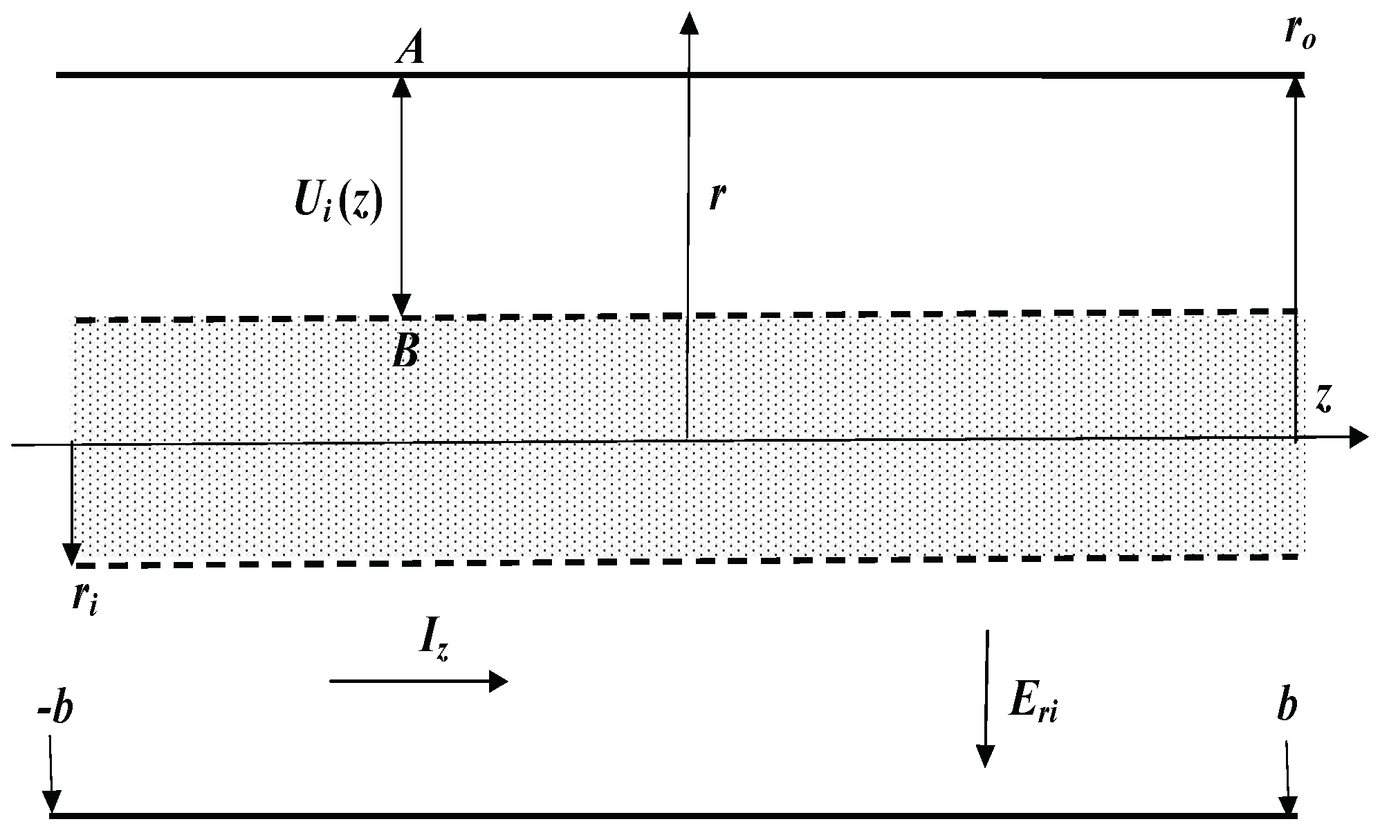
As seen in Figure 1, the superconducting sample consists in a hollow cylinder, characterized by its symmetry axis z and inner and outer radii . It is located in a cylindrical frame with coordinates (). Its length () is taken , in order to get rid of any end effect. The material contains conduction electrons of charge e, effective mass m and concentration . The current , flowing along the z axis, will be kept constant. Besides, the corresponding current density is homogeneous in the normal state (). It then reads
There is also[9] with standing for the electron mass center velocity. Thanks to the Ampère-Maxwell law, it gives rise, to an azimuthal magnetic field , which in turn exerts a radial Lorentz force on each electron
with being the permeability of vacuum. Then displaces the conduction electrons, which gives rise to a space charge density and thence to a radial electric field , such that ( stands for the electrical permittivity of vacuum). Finally, in the steady regime, is offset by , which results into the Hall voltage , measured between points in Figure 1. Thus read in the normal state
Hence measuring the Hall voltage gives access to the electron concentration . At last, several remarks are in order
- due to cylindrical symmetry, is independent from and in addition proportional to , unlike the usual Hall voltage proportional to , because the field itself is proportional to the current ;
- since the sign of cannot be predicted[9] in general, the experiment sketched above should be done first in the normal state, i.e. at , for calibration purposes, because is well known;
- due to different sample shape, i.e. parallelepiped versus cylinder, the superficial charge, giving rise to the electric field, lies at the outer edges of the sample in the traditional measurement, whereas it is a space charge, distributed over the whole bulk matter, in the experiment discussed here.
Figure 1.
Cross-section of the sample; the current and the electric field (), aroused by the Hall effect, are respectively parallel to the axes, whereas the magnetic field , induced by , is along the azimuthal axis, that is normal to the axes; refers to the case of the normal metal, whereas correspond respectively to the quantum and classical analyses for a superconductor; the matter (dotted area), making up the cylinder of radius , delineated by the dashed lines, is to be carved out to measure the Hall voltage between
3. Quantum Approach
Let the sample, depicted in Figure 1, be cooled down with kept constant for time . Actually, it does not become superconducting until , at which is low[10] enough, so as to fulfil with referring to the critical current density. Note that, due to irreversible Joule dissipation resulting from the finite ac resistivity in the superconducting state[7,11], there is no one to one correspondence between and , so that, contrary to an ubiquitous misconception[1,15], the phrase “critical magnetic field” is meaningless. Conversely, the critical current is well-defined, because the current density together with temperatureT do characterise[10] the thermodynamical state of every superconductor, as recalled below in section V.
It is then argued[4] that, once the sample becomes superconducting, the Lorentz force, combined with some undefined quantum force[4], push the electrons outward along the radial axis, which causes the current density to become r dependent but to remain independent from z for in the steady regime, defined by . Then reads[4]
for which refer to London’s length[1,2] and the concentration of superconducting electrons, respectively. In addition, can be assigned to its value by requiring
By proceeding furthermore as in the previous section, the magnetic field , the Lorentz force , the electric field and the resulting Hall voltage are worked out to read
Hence can be known by measuring owing to Eq.(6).
However several issues appear questionable in this analysis[4]:
- it relies upon London’s equation[2]with being the magnetic induction, parallel to the z axis, and the persistent current density, parallel to the azimuthal axis. Actually, the validity of Eq.(7) has been ascertained[7], but for infinite electrical conductivity, whereas the ac conductivity has been proved[11] to be finite on the basis of low-frequency susceptibility data[12,13], which thereby invalidates Eq.(7). As another consequence of finite ac conductivity, the thermodynamical state, characterising the superconducting sample in the steady regime , depends[14] upon . At last, though Eq.(7) has been worked out[2,7] for a magnetic fieldparallel to the z axis, and azimuthal current, it is applied[4], with no justification, to a physical case, characterised by an azimuthal field and current flowing along the z axis. Accordingly, since Eq.(7) ensues[7] from solving Maxwell’s equations for a transient regime (), the claim, that it applies as well to a steady regime[4] () with undefined , is groundless;
- the origin of the quantum force is self-admittedly[4] unknown, as is the expression of the potential, which it is supposed to derive from, so that this very phrase is actually misleading. In addition, the matching conditions[4] at require a persistent radial current to flow in the steady regime . Then the azimuthal magnetic field , acting on , will give rise to a Lorentz force, parallel to the z axis, which will cause eventually to grow till the critical value is reached and the sample goes thereby normal, which contradicts the assumption[4] of a stable, steady regime;
-
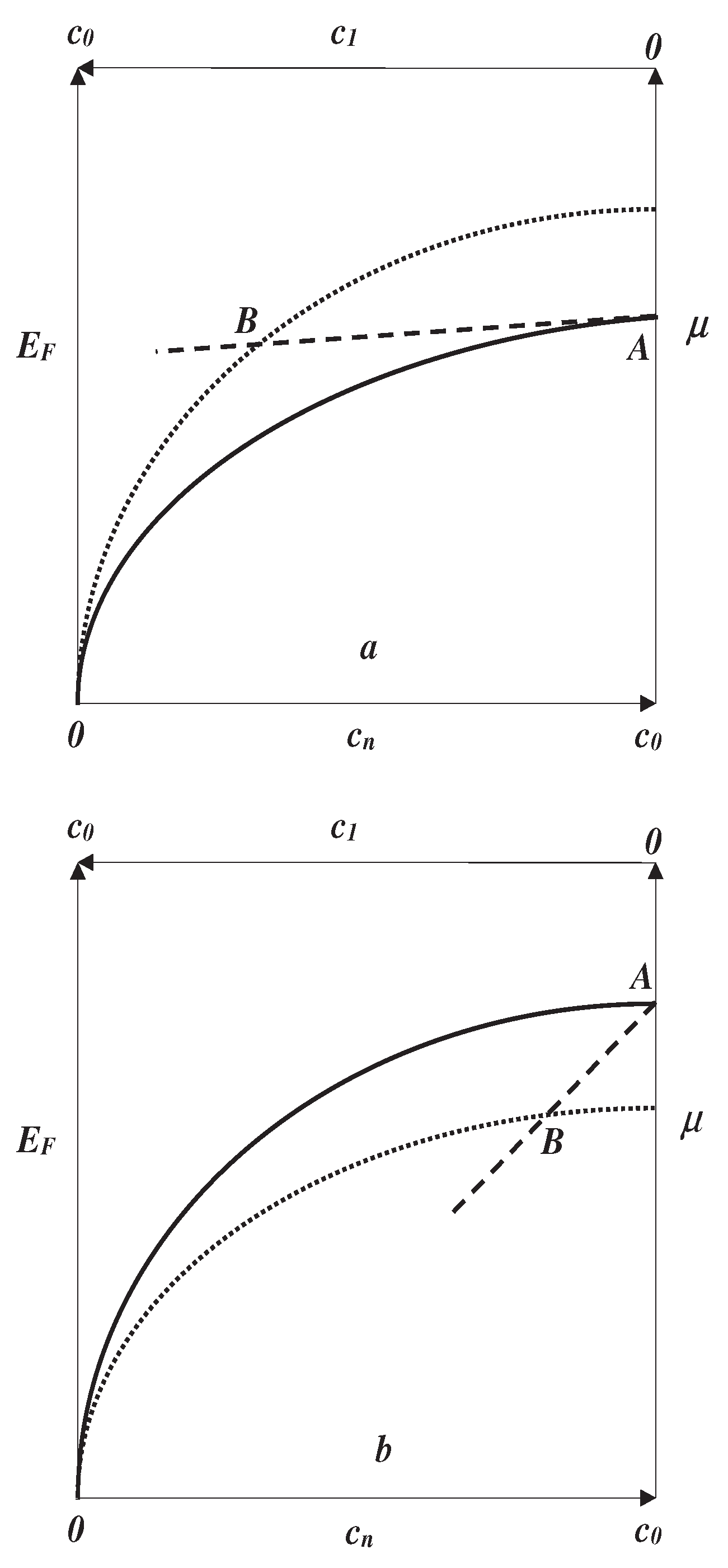
a key assumption[4] says that the current should be carried by holes in the normal metal. This entails that the Fermi energy ought to be close to the Van Hove singularity[9], located at the upper edge of the one-electron band . Consequently, there is for a three-dimensional sample[9], with standing for the one-electron density of states and energy, respectively. Then it implies finally . However such a condition will be proved below to be at loggerheads with a thermodynamical rationale, showing the opposite, namely a stable superconducting phase requires.As shown elsewhere[16], there iswherein is Boltzmann’s constant and has been reckoned at fixed normal electron concentration . Hence at fixed T looks as plotted in Figure 2a, Figure 2b, for and , respectively. The infinite slope is typical of a 3 dimensional Van Hove singularity[9], associated with the bottom of the conduction band. Note that Figure 2 displays ( refers to the chemical potential of superconducting electrons[10,17]), which has been shown to be a prerequisite for persistent currents[17], thermal equilibrium[10], occurrence of superconductivity[16,18] and the Josephson effect[19]. The two-fluid system, comprising normal and superconducting electrons in respective concentration (charge conservation requires ), is at thermal equilibrium at , provided the following equation is fulfilled[16,17,18]Eq.(8) means that the free energy of the whole electron system is stationary at fixed T. However, as shown elsewhere[17], Figure 2a and Figure 2b depict, respectively, the case of stable () and unstable () equilibrium. This statement of fact completes the proof that the hole-driven superconductivity[4] cannot be observed because it implies . Likewise, for the reader’s convenience, we recall[16,18] the necessary conditions for a second order transition to occur at
4. Classical Approach
The magnetic susceptibility not being continuous at has been shown[7] to be responsible for the Meissner effect taking place in a superconductor, cooled in a static magnetic field. Since no paramagnetic contribution has ever been observed in the superconducting state[1,9], the latter is deemed to be in a macroscopic singlet spin state, so that its susceptibility is determined entirely by Lenz’s law[7]. Meanwhile the magnetic susceptibility of normal electrons comprises[9] two components, respectively paramagnetic (Pauli) and diamagnetic (Landau), and is in general . Thus the local, magnetic inductions , both being parallel to the azimuthal axis, read, respectively, in the superconducting and normal states
Due to , the magnetic induction undergoes a finite step at
where refers to the time needed in the experimental procedure for T to cross . Owing to the Faraday-Maxwell equation, may induce two transient, electric fields , respectively parallel to the axes, such that
Let us begin with showing . The proof is by contradiction. As a matter of fact, implies that the voltage drop
is r-dependent too. But this is inconsistent with being r-independent at , i.e. at the interface with the leads, straddling the superconducting sample, because they are made out of normal metals, which entails being r-independent for any z. Q.E.D.
Meanwhile, will give rise to a transient z-dependent voltage
Observing could buttress the validity of this analysis.
Hence, due to the current density remaining r-independent in the steady regime , the calculation of proceeds as that of in Eq.(3), except for the concentration of superconducting electrons showing up instead of
Comparing Eq.(6) with Eq.(9) leads to . Therefore an independent determination of the concentration of superconducting electrons is needed to assess the respective validity of the quantum and classical analyses. This is the purview of the next section.
5. Skin Effect
An electromagnetic field of frequency , shone on a metal, remains confined[20] within a thin layer of thickness , called the skin depth, and located at the outer edge of the conductor, for , where Hz stands for the plasma frequency. This stems from the real part of the dielectric constant being negative for . Drude’s conductivity and have been shown to read[7,21]
are the concentration of superconducting electrons and their associated scattering time[9,20], respectively, and . Note that the normal electrons play no role, because their conductivity is . Then, thanks to , measuring would give access to , provided m is known. Nevertheless several remarks are in order, concerning the measurement :
- there being a one to one correspondence for conductivity and current density[10] , illustrated byentails that depends on j, so that measurements of the skin depth and the Hall voltage should be performed with the same current . Besides, as for the quantum case[4], the r-dependent leads to a r-dependent concentration , which complicates further the interpretation of the Hall effect experiment;
- in pure materials, is likely to lie in the microwave range (Hz), while it might rather belong in the IR one (Hz) for poor conductors such as high- compounds.
6. Conclusion
The properties of the current-induced Hall effect have been presented. It has been argued that it might shed light on the very nature of the force at work in the Meissner effect, i.e. either quantum or classical. The quantum explanation fails seemingly to account for the force giving rise to the eddy currents at , whereas the electrons, making up the eddy currents, are driven merely by Faraday’s electric field, induced by the magnetic susceptibility varying at within the classical interpretation.
Experiments, combining the current-induced Hall effect and the skin effect, have been discussed, which might enable one to assess the respective validity of each view. At last the skin depth measurement might help to chart the so far unknown , which is of great significance for the superconducting to normal transition[10].
Since the Hall voltage grows like the inverse of the electron concentration (see Eqs.(3,6,9)), it is in general much weaker in metals than in semiconductors. This hurdle is even more daunting in type I superconductors [22], because the Meissner effect prevents the magnetic field from entering the sample. Thus the corresponding Hall voltage, equal to the circulation of the Hall electric field along the tiny London length, is likely to lie under the detection threshold. Conversely the experiment, discussed in section IV, does not suffer from this drawback, because the current induced magnetic field penetrates indeed into the whole bulk matter. Consequently, it could be performed even in high-Tc compounds at relatively high currents densities, yet giving rise to a magnetic field <Hc1 in the whole bulk matter (to avoid vortices building up) and thereby ensuring good sensitivity.
References
- Tinkham M.: Introduction to Superconductivity, Dover Books (2004).
- London F.: Superfluids, vol.1, Wiley (1950).
- Henyey F. S., Phys.Rev.Lett., 49, 416 (1982).
- Hirsch J.E., Phys.Lett.A, 413, 127592 (2021).
- Assis A.K.T., Tajmar M., Ann.Fond.Louis de Broglie, 42, 307 (2017).
- Prytz K. A., Prog.Electromagn.Res.M, 64, 1 (2018).
- Szeftel J., Sandeau N., Khater A., Prog.Electromagn.Res.M, 69, 69 (2018).
- Meissner W., R. Ochsenfeld, Naturwiss., 21, 787 (1933).
- Ashcroft N.W., Mermin N. D.: Solid State Physics, Saunders College (1976).
- Szeftel J., Sandeau N., Abou Ghantous M., J.Supercond.Nov.Magn., 33, 1307 (2020).
- Szeftel J., Abou Ghantous M., Sandeau N., Prog.Electromagn.Res.L., 81, 1 (2019).
- Maxwell E., Strongin M., Phys.Rev.Lett., 212, 10 (1963).
- Strongin M., Maxwell E., Phys.Lett., 49, 6 (1963).
- Szeftel J., Sandeau N., Abou Ghantous M., Khater A., EuroPhys.Lett., 131, 17003 (2020).
- Parks R.D.: Superconductivity, CRC Press (1969).
- Szeftel J., Sandeau N., Abou Ghantous M., El Saba M., J.Supercond.Nov.Magn., 34, 37 (2021).
- Szeftel J., Sandeau N., Abou Ghantous M., Eur.Phys.J.B, 92, 67 (2019).
- Szeftel J., Sandeau N., Abou Ghantous M., El Saba M., EuroPhys.Lett., 134, 27002 (2021).
- Szeftel J., Sandeau N. and Abou Ghantous M.: J.Supercond.Nov.Magn., 35, 65 (2022).
- Born M., Wolf E.: Principles of Optics, Cambridge University Press (1999).
- Szeftel J., Sandeau N., Khater A., Phys.Lett.A, 381, 1525 (2017).
- Reed W.A., Fawcett E., Kim Y.B., Phys.Rev.Lett., 14, 790 (1965).
Figure 2.
schematic plots of , and as solid, dotted and dashed lines, respectively; cases correspond to and , respectively; has been taken to be constant for simplicity; the origin is set at the bottom of the conduction band; the crossing points of with in Figure 2a,b exemplify stable and unstable solutions of Eq.8, respectively; the tiny differences and have been hugely magnified for the reader’s convenience
Disclaimer/Publisher’s Note: The statements, opinions and data contained in all publications are solely those of the individual author(s) and contributor(s) and not of MDPI and/or the editor(s). MDPI and/or the editor(s) disclaim responsibility for any injury to people or property resulting from any ideas, methods, instructions or products referred to in the content. |
© 2024 by the authors. Licensee MDPI, Basel, Switzerland. This article is an open access article distributed under the terms and conditions of the Creative Commons Attribution (CC BY) license (http://creativecommons.org/licenses/by/4.0/).
Copyright: This open access article is published under a Creative Commons CC BY 4.0 license, which permit the free download, distribution, and reuse, provided that the author and preprint are cited in any reuse.


