1. Introduction
Early detection, localization and estimation of structural damage is nowadays one of the most important engineering problems that has focused much attention over the last years. When a defect occurs in the structural element, it can seriously disrupt its functioning. There are different non-destructive techniques which enable the identification of defective part of a structure, most of them base on the analysis of the structural response signals. Different approaches and many advanced methods have been developed, e.g. radiography [
1], ultrasonic [
2], acoustic emission [
3], magnetic field [
4], and eddy current [
5] methods. Damage identification method which combines empirical mode decomposition (EMD) and Autoregressive Integrated Moving Average (ARIMA) models was presented in [
6]. Thermal testing [
7] or making use of RGB-D camera [
8] also proved to be an effective method in structural health monitoring. A great potential is assigned to soft methods, mainly evolutionary algorithms [
9] and artificial neural networks [
10].
Different types of structural response, namely eigenfrequencies, displacements, angles of rotation, velocities or accelerations can be useful to assess the reliability of the structure. The method which enables to extract the desired detailed information from a numerous data representing the global response of a defective structure is called Wavelet Transform (WT). In the paper it is applied in its discrete form (DWT). An indicator of the damage presence and location in this type of analysis are strong disturbances of the transformed signal. Previous studies of the authors [
11,
12,
13] proved that, in the class of considered problems, the most effective appeared to be the Daubechies wavelet [
14]. Similar study has been carried out for damage detection in beams [
15] and mining machines [
16]. The comparison between the efficiency of Haar, Daubechies and Coiflet wavelet in damage detection was discussed in [
17]. Wavelet functions proved to be highly useful in many applications as well, including their implementation to the theory of homogenization [
18].
Steel masts are the lightweight structures, which behaviour has been discussed in many papers, e.g. the dynamic analysis was presented in [
19] and analysis taking into account the geometric and physical non-linearity of the guys in [
20]. In the present work, the authors took up the topic of analyzing a mast with guy cables, taking into account their weakening, the location of which is made possible by the use of the Discrete Wavelet Transform in the analysis of the structure’s response signal.
2. Theoretical foundations
2.1. Discrete Wavelet Transform (DWT)
At the beginning of theoretical considerations, let there be a given function
, which is continuous and belong to the field of
. This function may be called the wavelet function (mother function) and must satisfy the condition of admissibility [
17]. The mother function may be real- or complex-valued. The real-valued wavelets will be applied in the considered cases. For signal decomposition the set of wavelets (wavelet family) is needed. This set of functions is obtained by translating and scaling the function
ψ, what can be written by means of the relation:
where t is a time or space coordinate, a and b are the scale and translation parameters respectively. The parameters a and b take real values and additionally . The element expresses the scale factor which ensures the constant wavelet energy regardless of the scale, i.e. .
In the present analysis, Discrete Wavelet Transform (DWT) plays the leading role. The wavelet family can be obtained by substitution
and
in Equation (2.1). This yields the relation:
in which k and j are scale and translation parameters, respectively.
The Discrete Wavelet Transformation (DWT) of the signal (e.g. the response function of the structure)
is expressed by the equation:
The scalar product of the response function and the wavelet function allows to find the set of wavelet coefficients .
In identifying of singularities of the tested signals the vanishing moments of the wavelet function play a significant role. A wavelet has
k vanishing moments if the subsequent relation is fulfilled:
The wavelet of order n has vanishing moments and is orthogonal to polynomials up to .
In the case of above mentioned Daubechies wavelets which are of order from 2 to 20, always even numbers, a number of vanishing moments equal to half of the order, e.g. for Daubechies 4 there are 2 vanishing moments. Vanishing moments restrict the capability of wavelets to represent polynomial behavior or information in a signal, meaning that, e.g. Daubechies 6 encodes constant, linear and quadratic signal components.
For 1-D DWT analysis, decomposition of the discrete signal is carried out according to the Mallat pyramid algorithm [
21] which can be generally presented in the simple form:
where each component in signal representation is coupled with a specific range of frequency and provides information at the scale level . The discrete parameter describes the level of a multi-resolution analysis (MRA), expresses the smooth signal representation, is the detail of the transformed signal at the scale level and corresponds to the most detailed representation of the transformed signal. The function must be approximated by discrete values to fulfill the dyadic requirements of DWT.
2.2. Finite Element Method
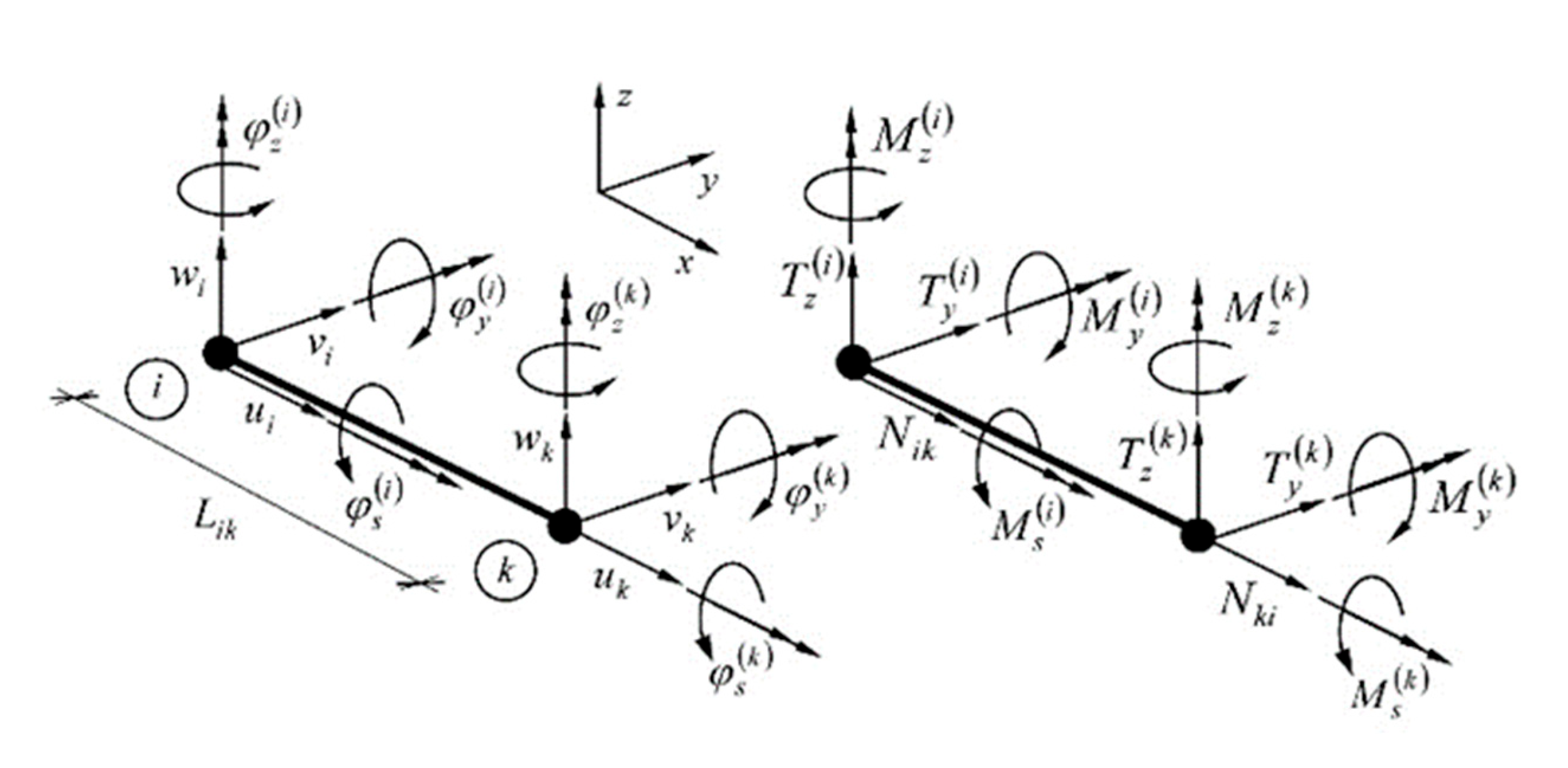
The Finite Element Method (FEM) has been applied to the numerical, geometrically non-linear analysis of the antenna guyed mast. The finite element describing the behaviour of the lattice part of the entire mast is shown in
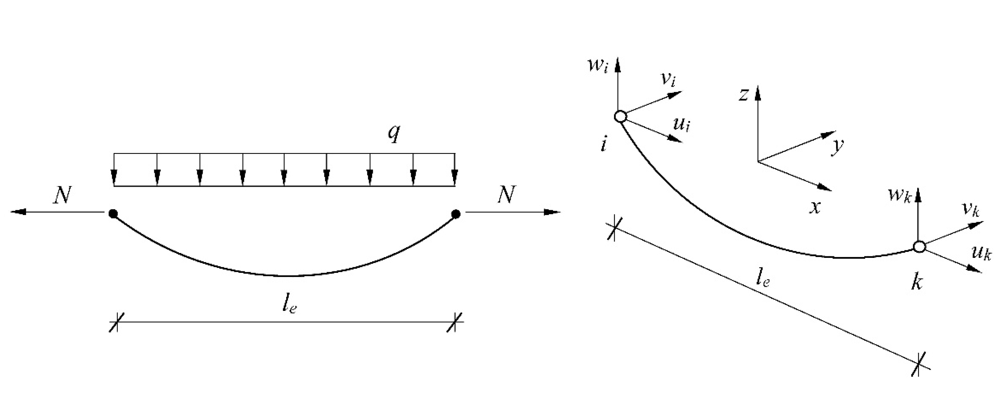
Figure 1. It is a typical two-node element with six degrees of freedom per node. The general description of the guy (cable) element is shown in
Figure 2.
The displacement formulation of the FEM carries a typical matrix notation:
where is the global structural stiffness matrix, is the global structural displacement vector and is the external loading vector.
The global stiffness matrix
is composed of three matrices:
where the first one
, is the classic linear stiffness matrix of the whole structure, the second one
is the first non-linear stiffness matrix, commonly called geometric matrix, whose terms depend on the value of the axial force and only on structural geometry (and at the level of a finite element on its geometry) and finally, the last one
is the strongly non-linear stiffness matrix that depends simultaneously on the geometry of the structure and displacements. These matrices can be derived in an uncomplicated way by writing the expression for the potential energy and postulating the equilibrium condition by its stationarity. An comprehensive description of non-linear stiffness matrices for a simple flat two-node element is given by Rakowski and Kacprzyk [
22] and similar procedures have been introduced here.
Cable non-linearity affects the calculation model and analysis by the initial geometry of the cable and, as a consequence, its finite element mesh, the initial tension of the cable, and finally linear and nonlinear behaviors of the element [
23].
3. Numerical Examples
The numerical analysis was performed for the antenna guyed mast described in paper [
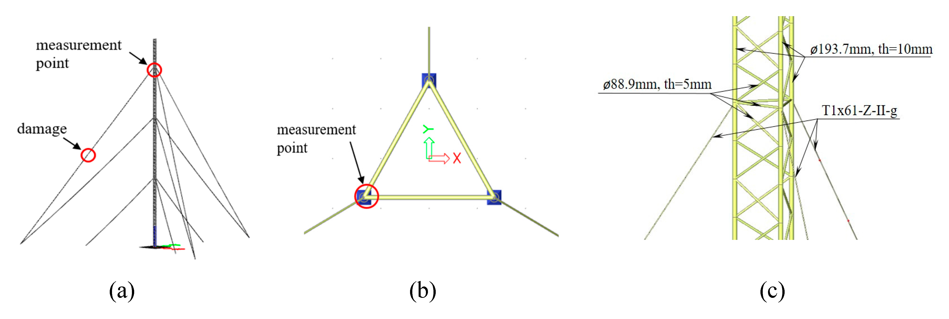
24] and shown in
Figure 3. The mast, 204 m high, is designed as a steel spatial truss with a triangular cross-section. The width of the truss side is 2.7 m. The edge bars are made of round tubes with a diameter of 193.7 mm and a wall thickness of 10 mm, while diagonals are made of round tubes with a diameter of 88.9 mm and a wall thickness of 5 mm. The mast has three levels of fastening guy lines in height of 67.18, 126.58 and 176.08 m. The parameters for the guy lines are as for steel rope with a diameter of 36 mm, T1x61-Z-II-g (7.66 cm
2) structure, made of wire with a strength of 1570 MPa and nominal strength breaking force 1195 kN. The assumed values of the initial tension of the guy cables at the individual attachment levels are, respectively: 40, 70, and 100 kN. As signals for the wavelet analysis, the displacements (u
tot) of the node in which the guy cable is connected to the mast truss were assumed. The values of these displacements were calculated numerically using the Finite Element Method, taking into account the non-linear theory.
The problem of mechanics (statics) of a three-dimensional truss structure with guy wires was solved using the Finite Element Method (FEM) in the commercial SCIA Engineer program [
25], appropriate to structural systems containing elements that require geometrically nonlinear analysis. The discrete structure response signal thus obtained was subjected to a Discrete Wavelet Transformation, which was carried out using the Mathcad package.
3.1. Case 1 – Variable Loading Force
In this model, the defect is modeled as 50% reduction of the cross-section within the length of 10 cm, is located in the middle of the guy cable fastened at the highest level (with a tension force of 100 kN). Moving concentrated vertical force
P = 100 kN was applied in 64 nodes with equal time intervals. The number of measurements
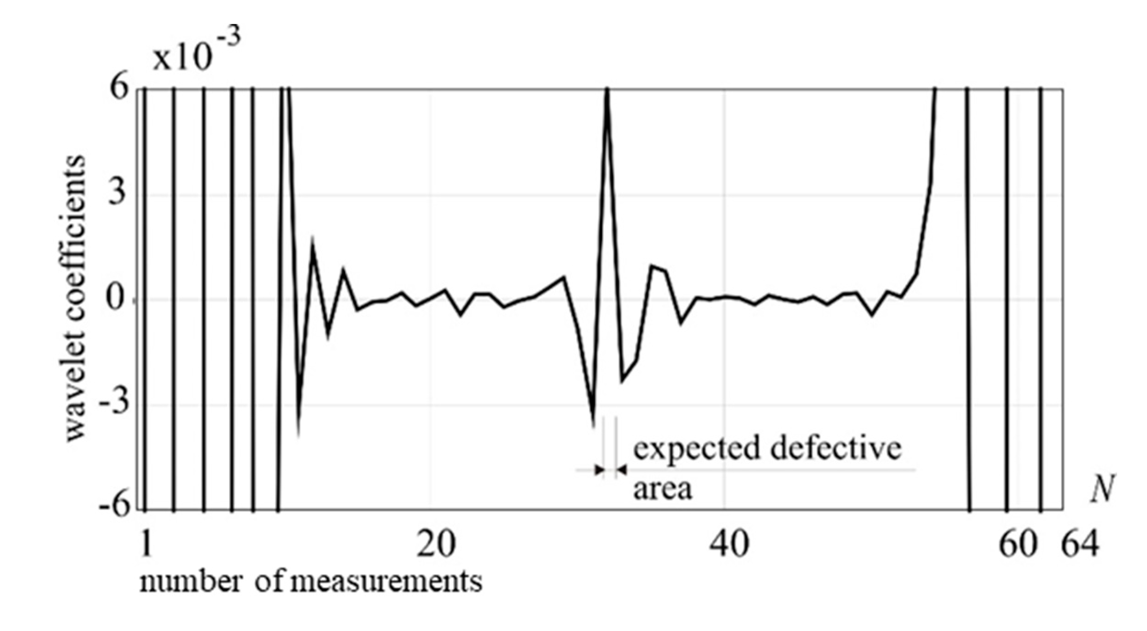
N = 64. The nodal points where the concentrated force is applied are located along the damaged cable structural element. The response signal has been analyzed and transformed using DWT procedures. The Daubechies 12 wavelet has been applied to the preliminary analysis. Performed analysis precisely indicate, by the clear peak in the transformation window (detail 1 – D1), the damage position, which is shown in
Figure 4.
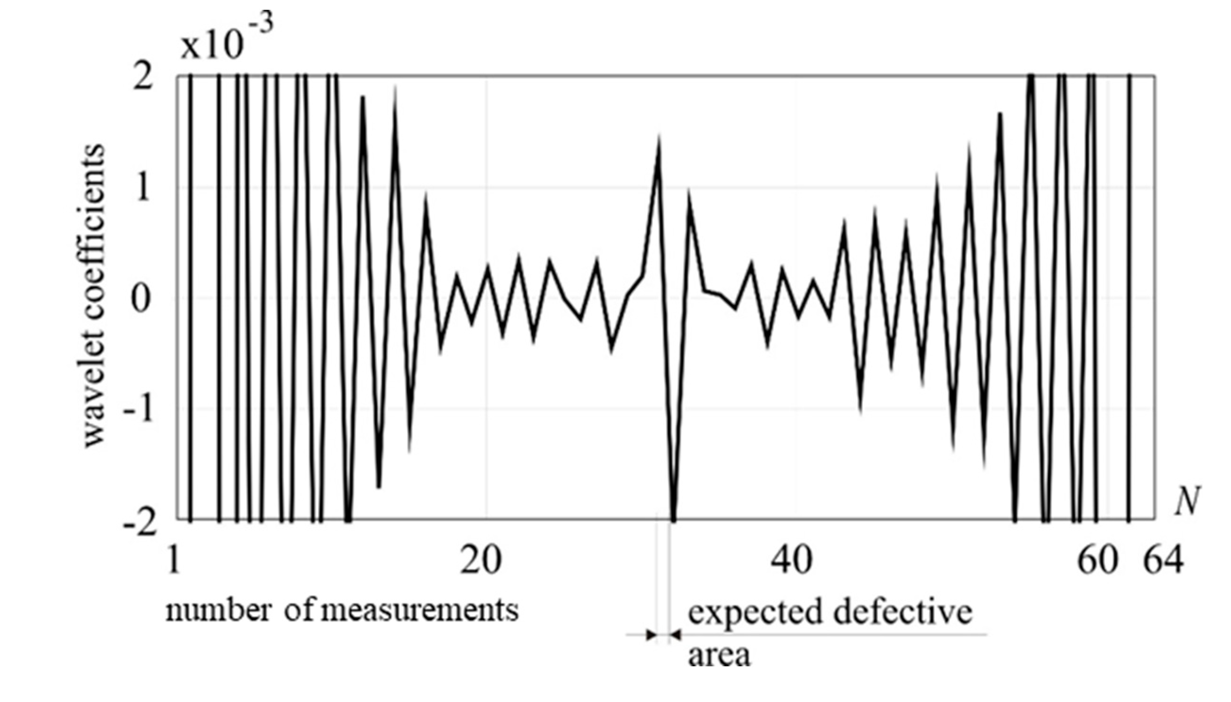
In the next calculations the weakening of the cross-section is introduced, as in the previous example (50 % reduction of the cross-section within the length of 10 cm and located in the middle of the guy cable which is fastened at the highest level). The tension force is 100 kN. The external loading force takes the following values: 25 kN, 50 kN, 100 kN and 150 kN.
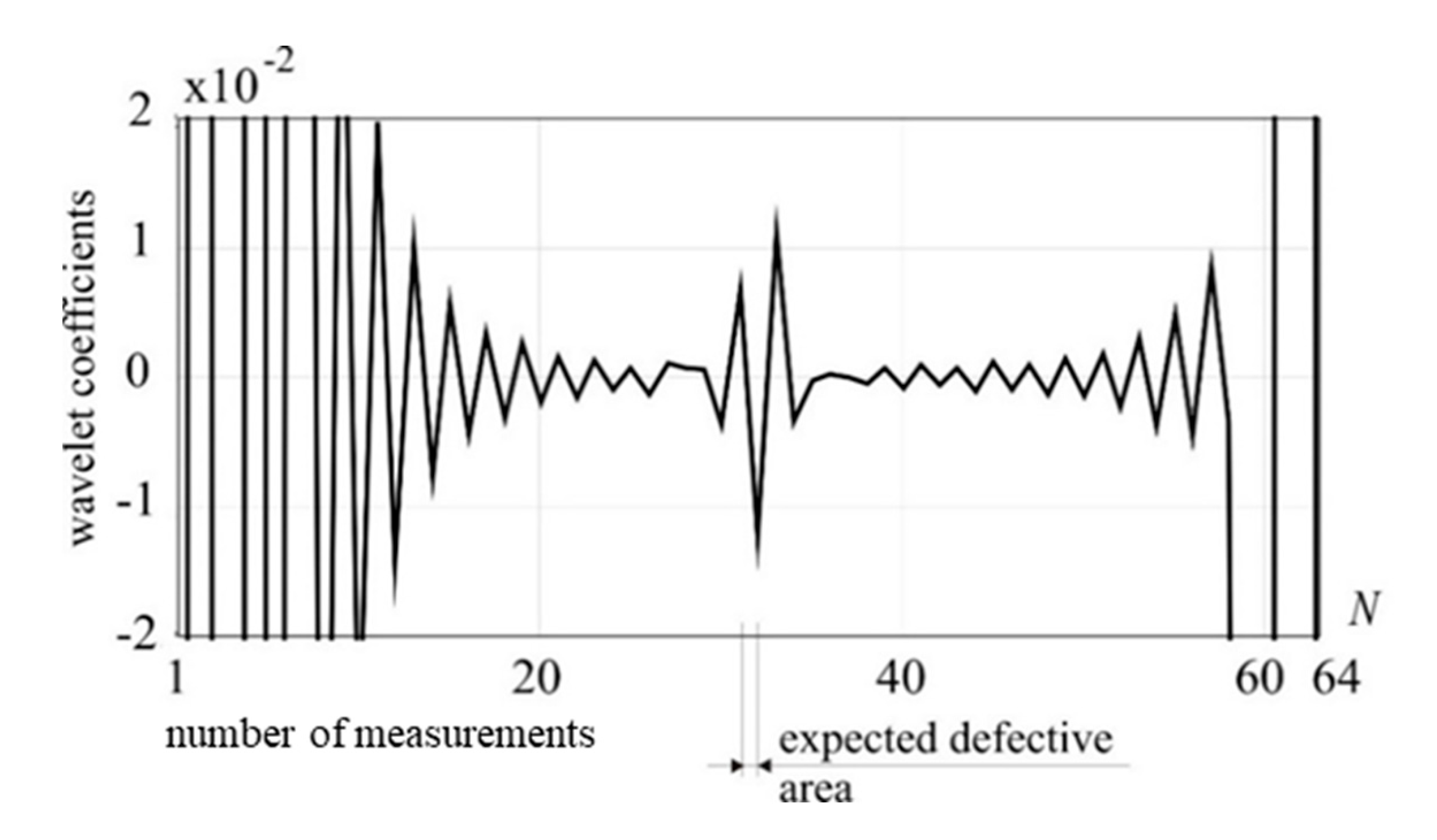
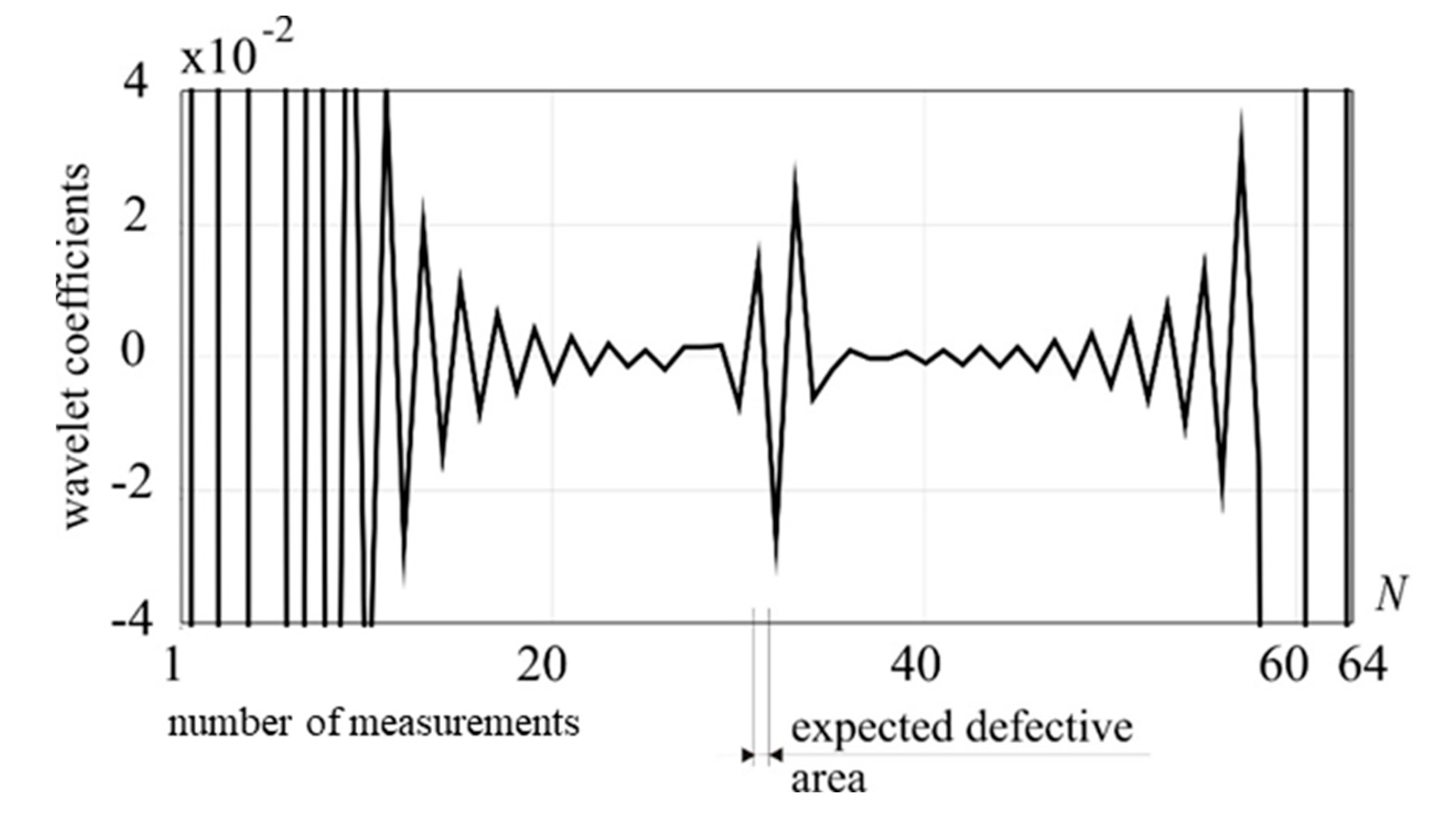
The DWT procedures have been carried out using Daubechies 8 wavelet family in all examples considered. The moving external vertical force was applied in the same way as in the previous example. The calculation results are shown in
Figure 5 and
Figure 6 for 25 and 50 kN, respectively. The presence of a defect was identified by a clear perturbation of the transformed signal.
Worth noting is that the shape of the decomposed with Daubechies 8 data is independent of the value of the external loading forces. The only change was observed in the range of wavelet coefficients which increased proportionally to the external loading force value. The results has been compiled in
Table 1.
The above observation is true if the value of external loading forces is sufficiently high, i.e. above 20 kN. Although, in the case of decomposition of a displacement structural response signal induced by the force of 5 kN with Daubechies 8 wavelet, the defect was correctly located, the disturbances occurring to the right and left hand side of the peaks indicating the defect in the transformation window already disrupt the unambiguity of the results (see
Figure 7).
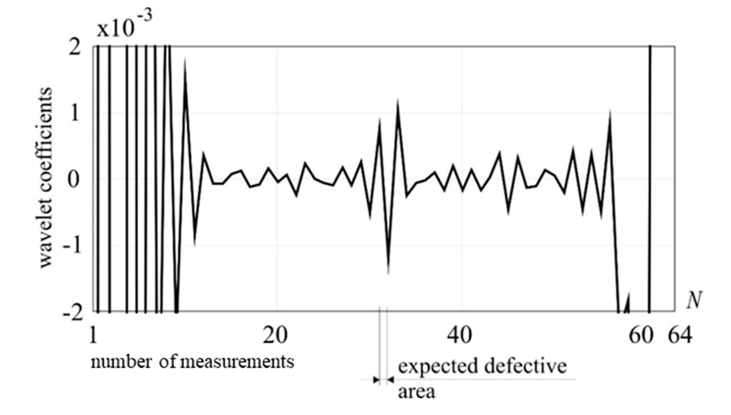
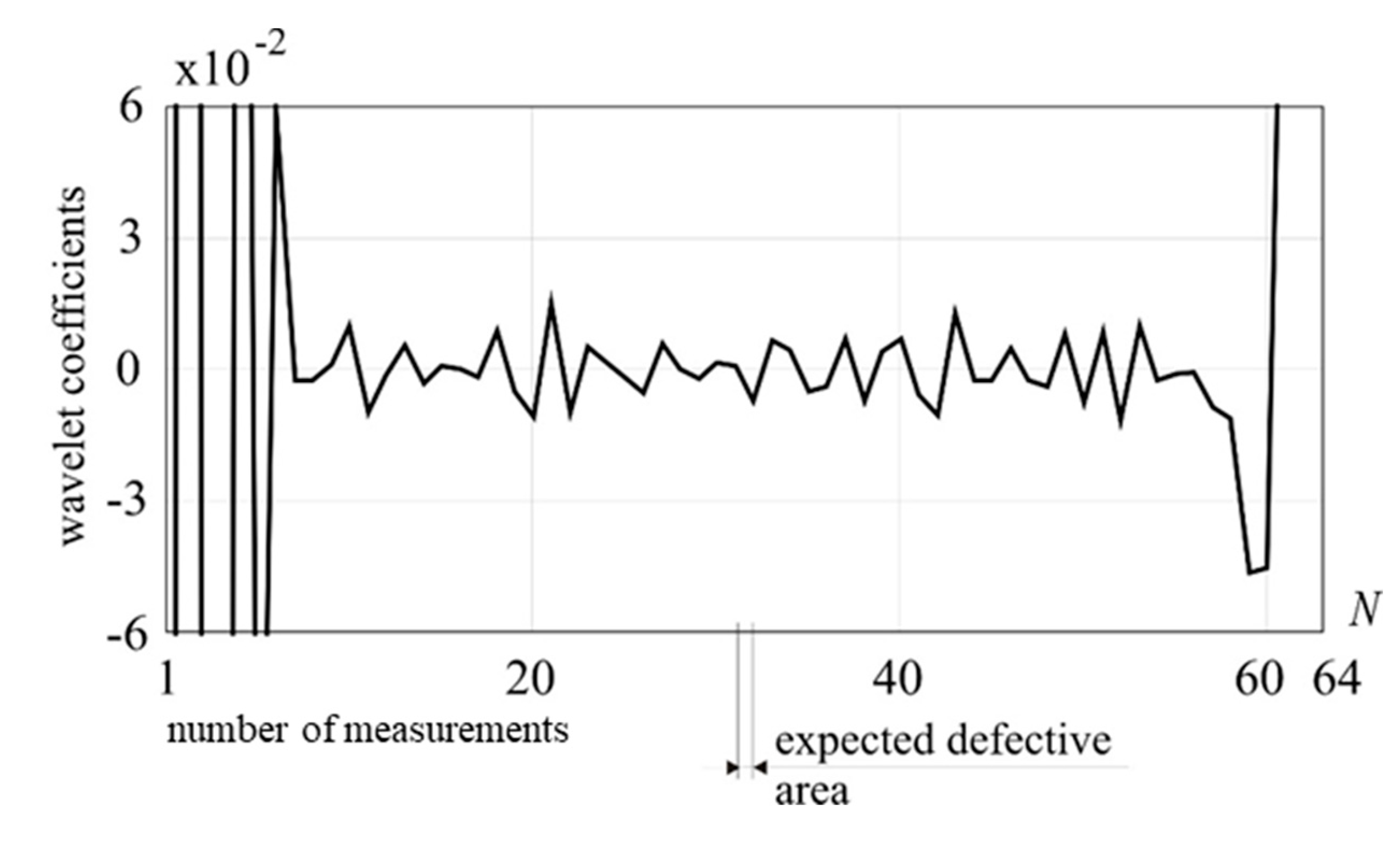
Finally, the external loading force value was reduced to 1kN. In this case the proposed method turned out to be ineffective for detecting damage, see
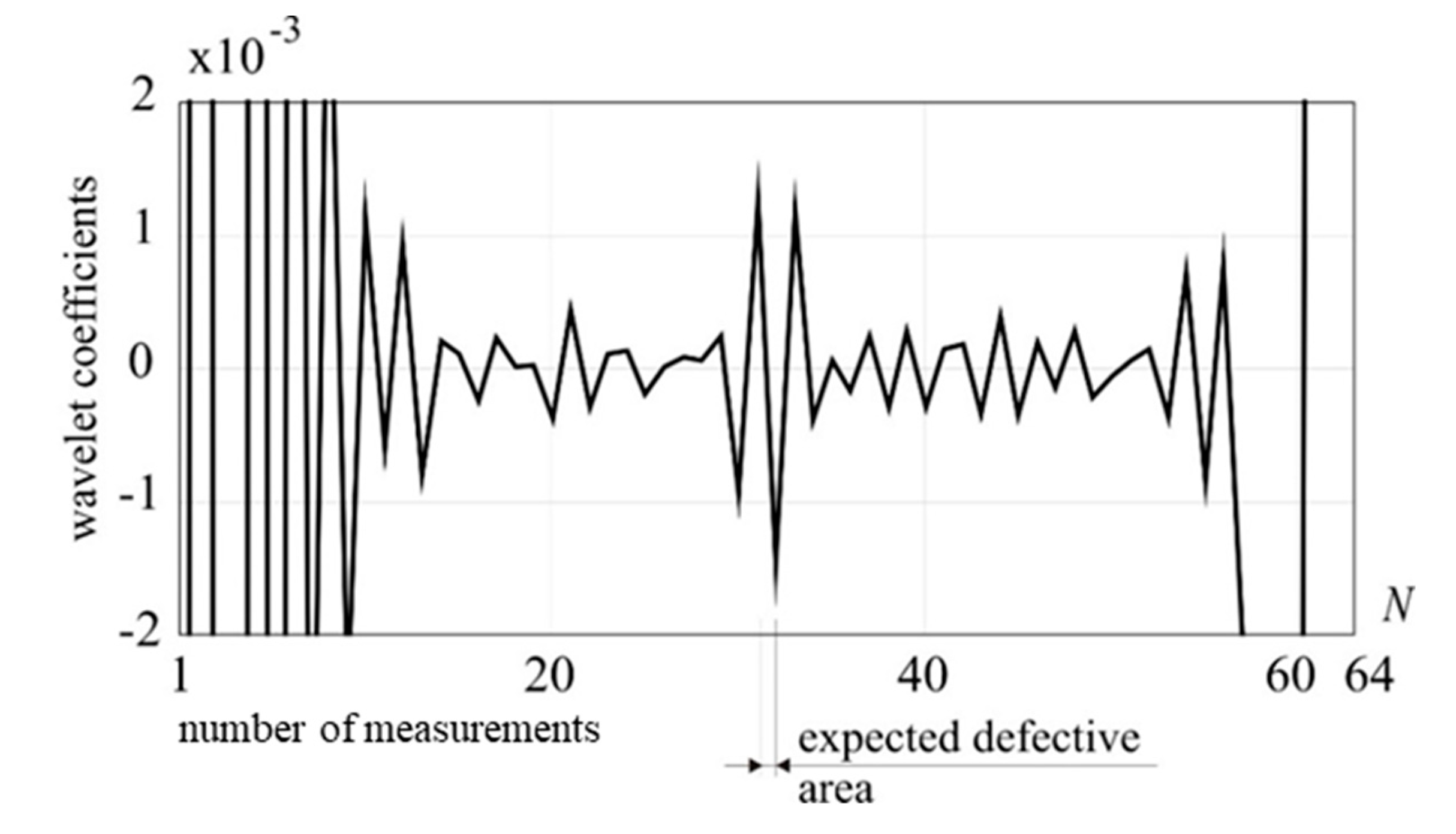
Figure 8. Even for increased wavelet order there are no disturbances in the transformed signal which is visible in
Figure 9. Further attempts to decompose the signal with higher order Daubechies wavelets, i.e. 10, 12, 14 did not bring satisfactory results, even though the intensity of defect was significant, i.e. 50% reduction on cross-section area in one FEM element. The higher details, namely detail 2, 3 and 4 of Daubechies 6 wavelet, were also considered; however, the damage was not detected.
3.2. Case 2 – Variable Damage Size
In the following examples the manner of introducing damage is identical to the previous ones. The damage intensity has been decreased to 25 % reduction of the cross-section within the length of 10 cm (the reduced cross-sectional area is located over a length of 10 cm, symmetrical to the entire length of the cable), the location is in the middle of the guy cable fastened at the highest level (with a tension force of 100 kN). The external loading force takes the value 5 kN. The number of mesurements is the same as in the previous model (N = 64).
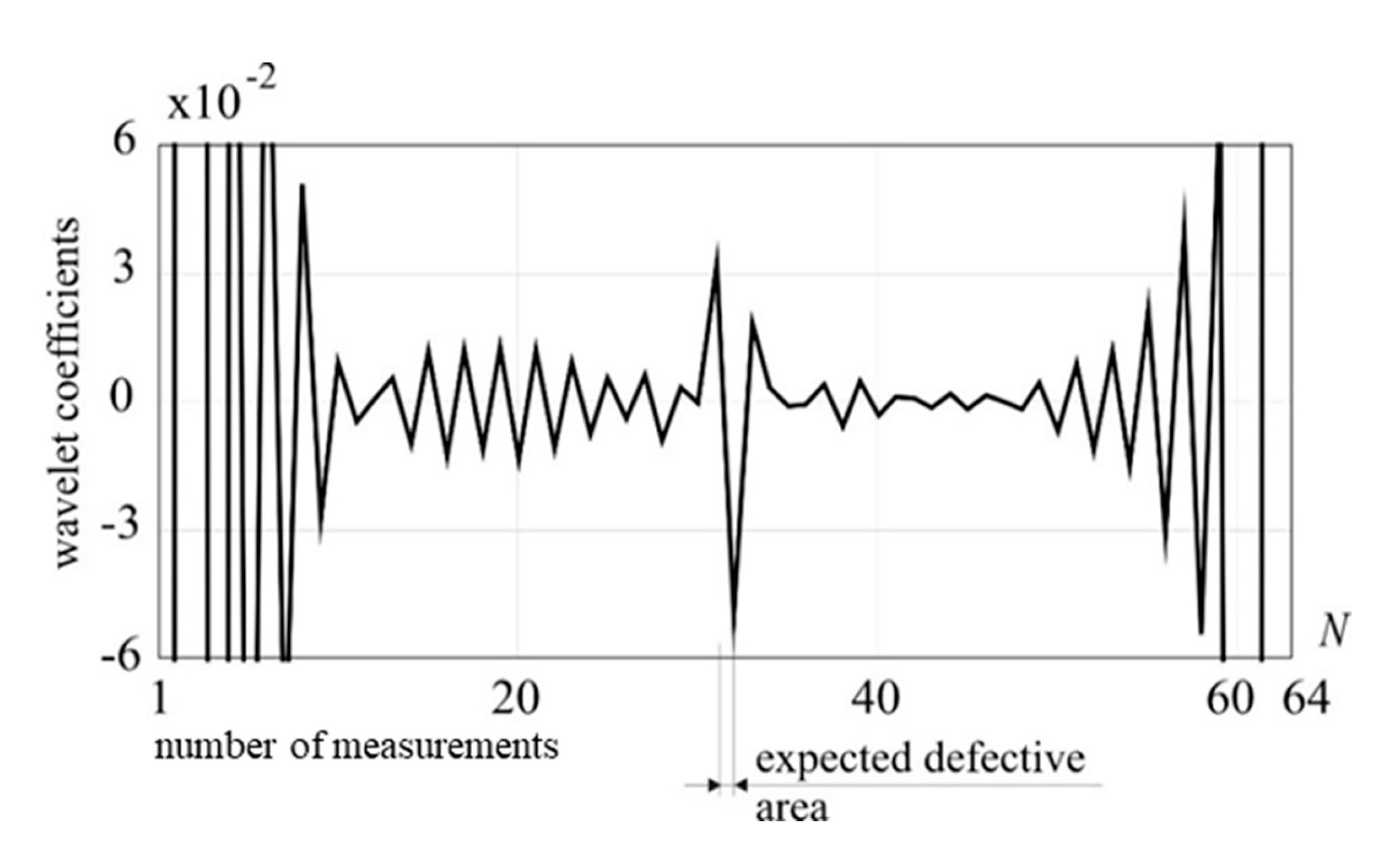
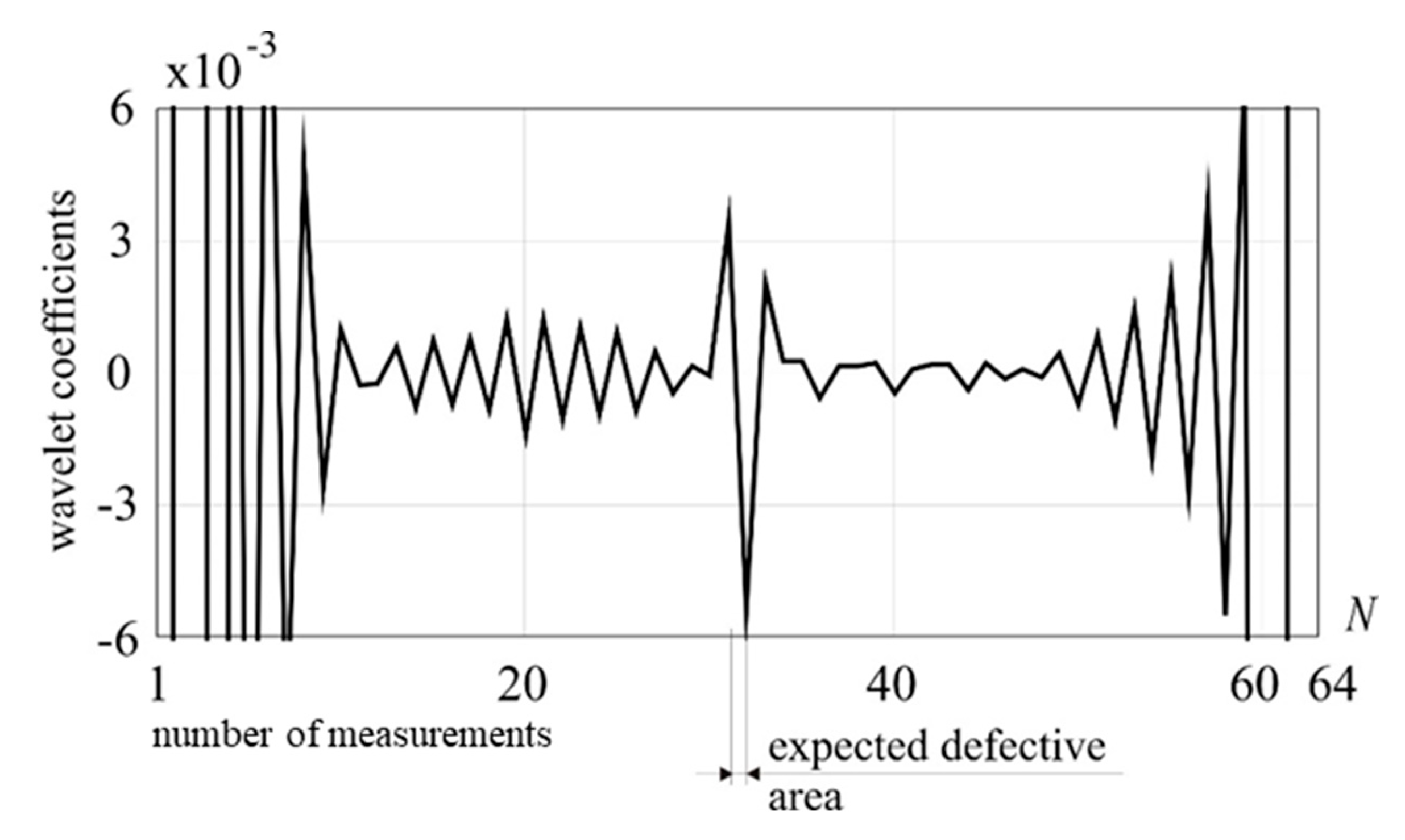
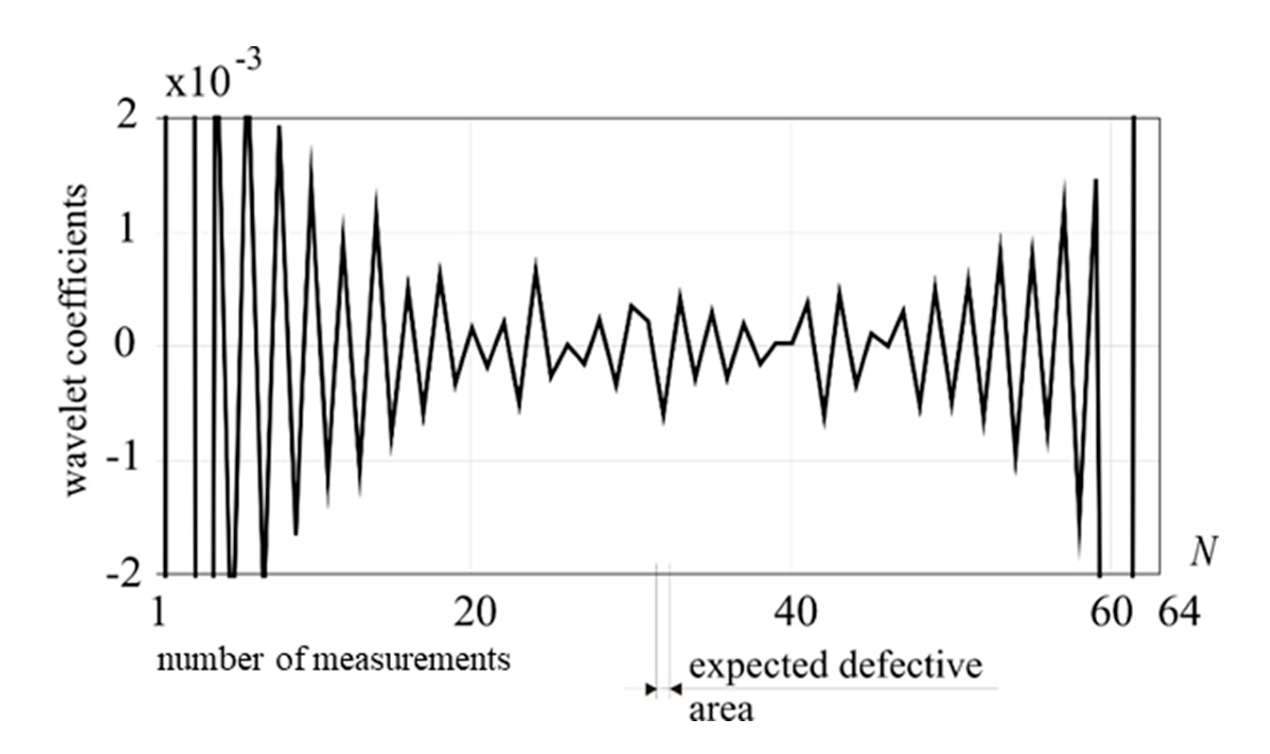
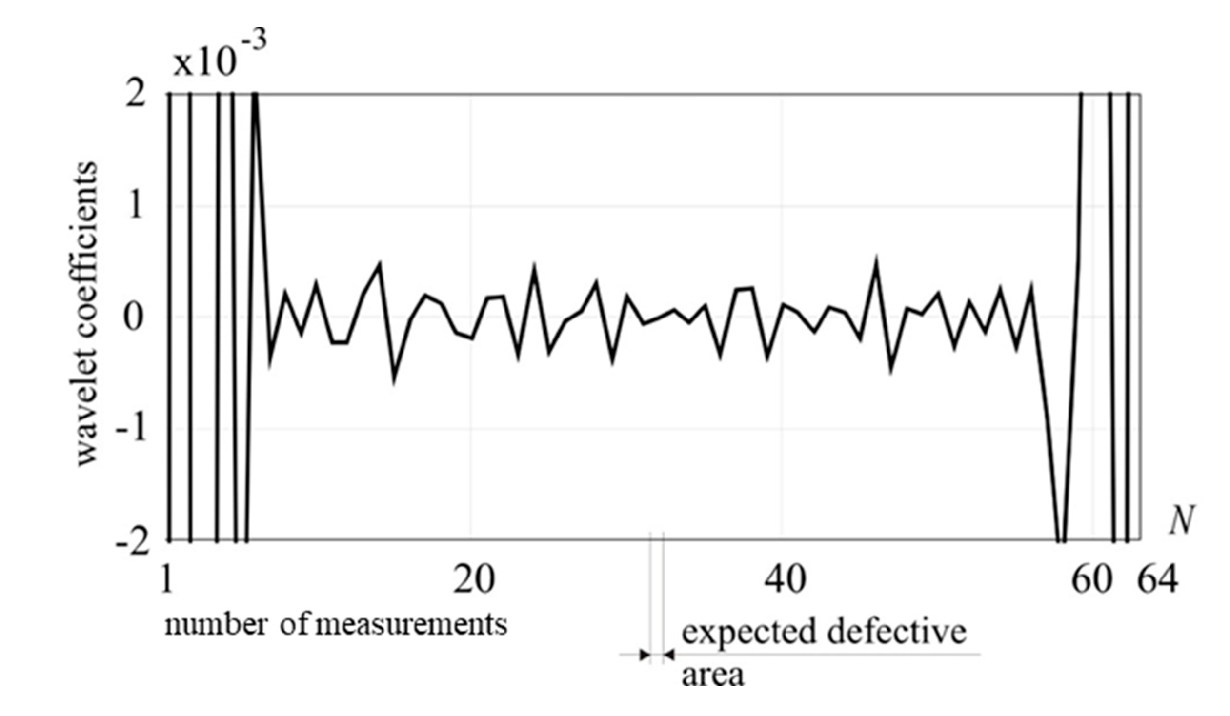
The DWT procedures have been carried out using subsequently Daubechies 8, 6 and 4 wavelet. The moving external vertical force was applied at 64 points (nodes) of the cable. The calculation results are shown in
Figure 10,
Figure 11 and
Figure 12.
The analyses presented in
Figure 10 and
Figure 11 clearly indicate the presence and location of the defect, whereas the signal decomposition depicted in
Figure 12 gives no information about the damage existence. This implies that the signal has constant, linear and quadratic components, because to reveal its singularity the wavelet with three vanishing moments, i.e. Daubechies 6, was necessary.
An attempt has been made to assess the impact of the successive reduction the damage intensity and external loading force on the effectiveness of the proposed method. In the subsequent analyses, 10% area of the cross-section reduction is assumed. The external loading force takes the value 5 kN.
The DWT procedure has been carried out while using Daubechies 6 wavelet. The external force was applied at 64 points (nodes) of the guy cable. The results are presented in
Figure 13, where evident disturbance of the transformed signal is an indicator of the defect presence and location can be observed.
3.3. Case 3 – Variable Tension Force
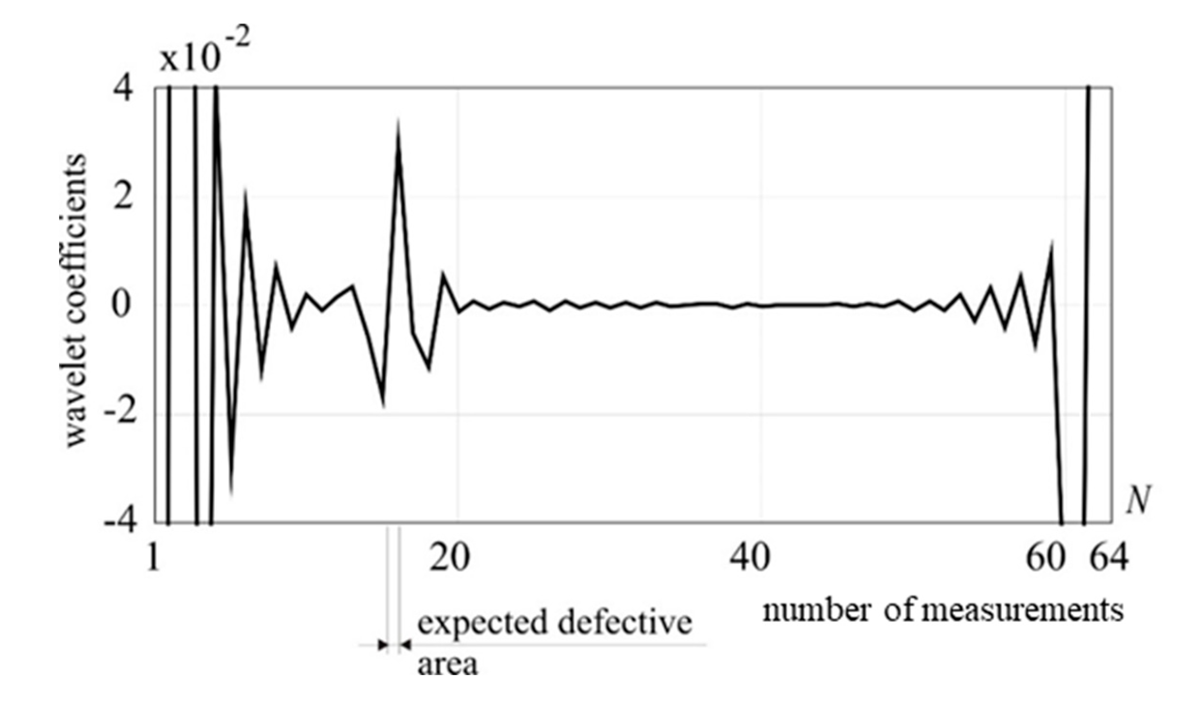
Subsequently, the effect of increasing the cable tension force on the efficiency of damage detection while applying DWT was examined. In the analyses, 25% area of the cross-section reduction is assumed, the external loading force applied at 64 points (nodes) of the guy cable takes the value 5 kN. In the first step, the tension of the guy cable has been increased from 100 kN to 150 kN.
The signal transformation using Daubechies 6 wavelet for tension force 150 kN is presented in
Figure 14. The high peak clearly indicates the presence and position of the defect.
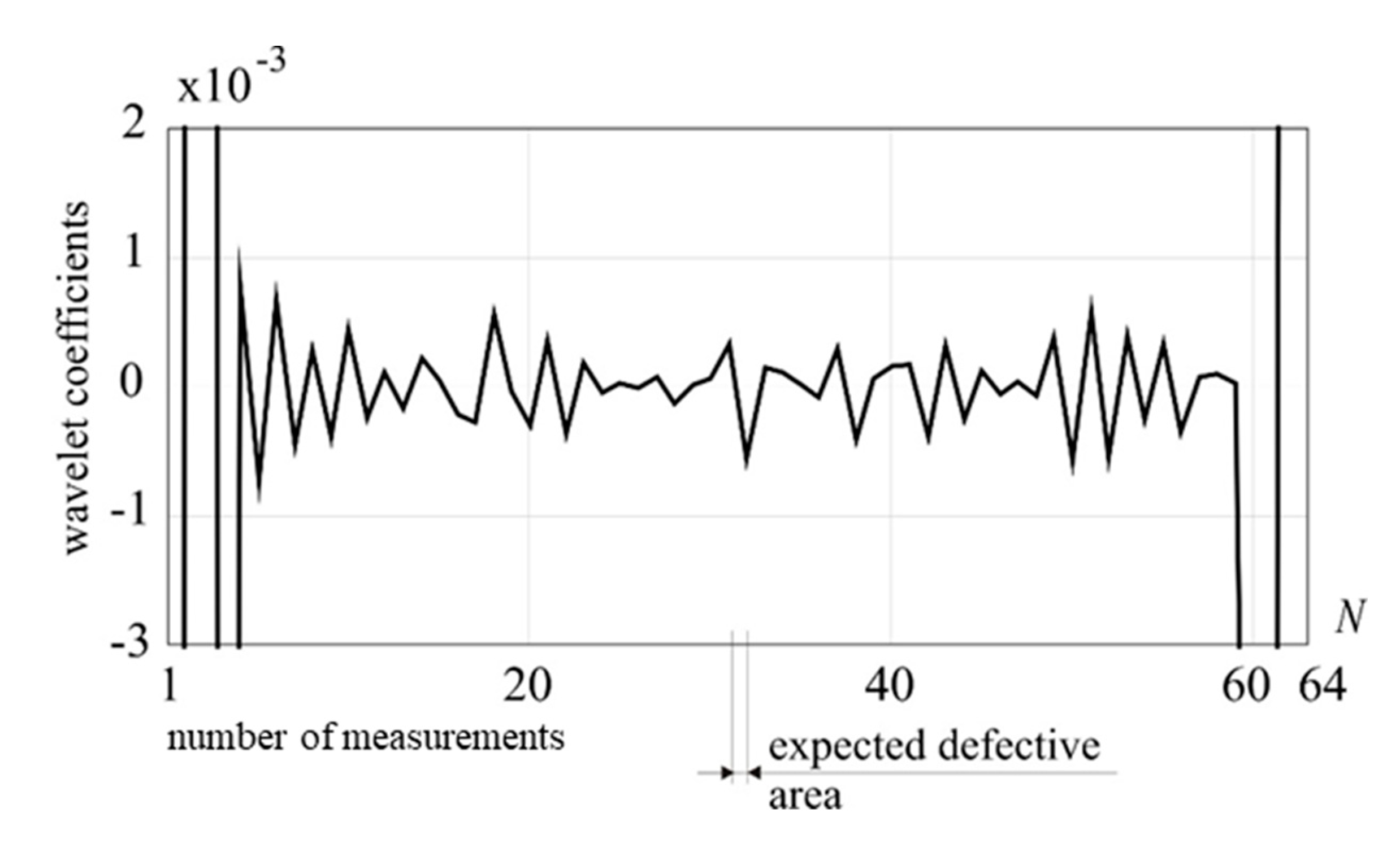
In the second step, the tension of the guy cable has been increased to 200 kN. The DWT of the obtained response signal, neither with Daubechies 6 (see
Figure 15) nor Daubechies 8 wavelet (see
Figure 16), did not indicate the existence of the damage.
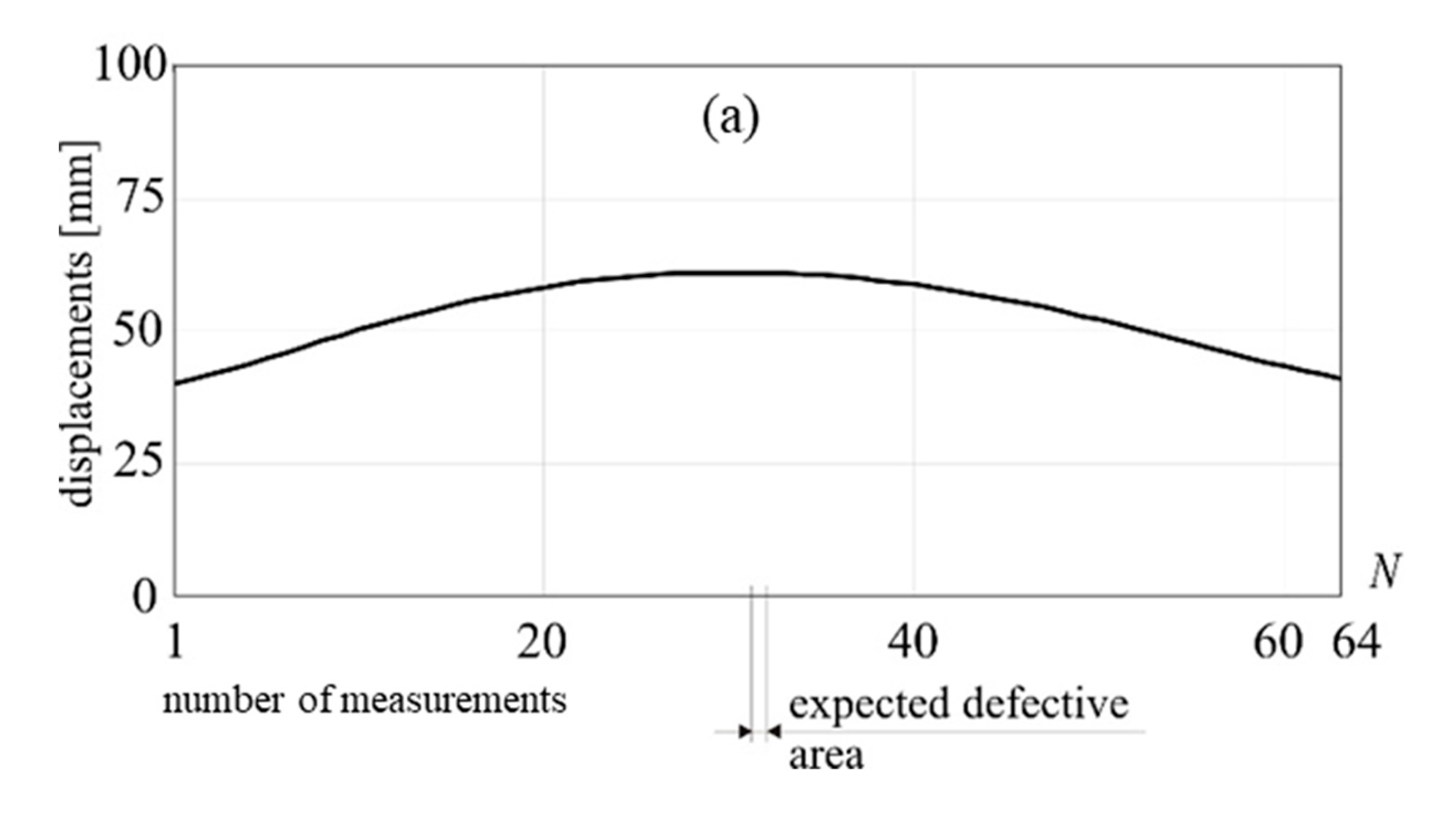
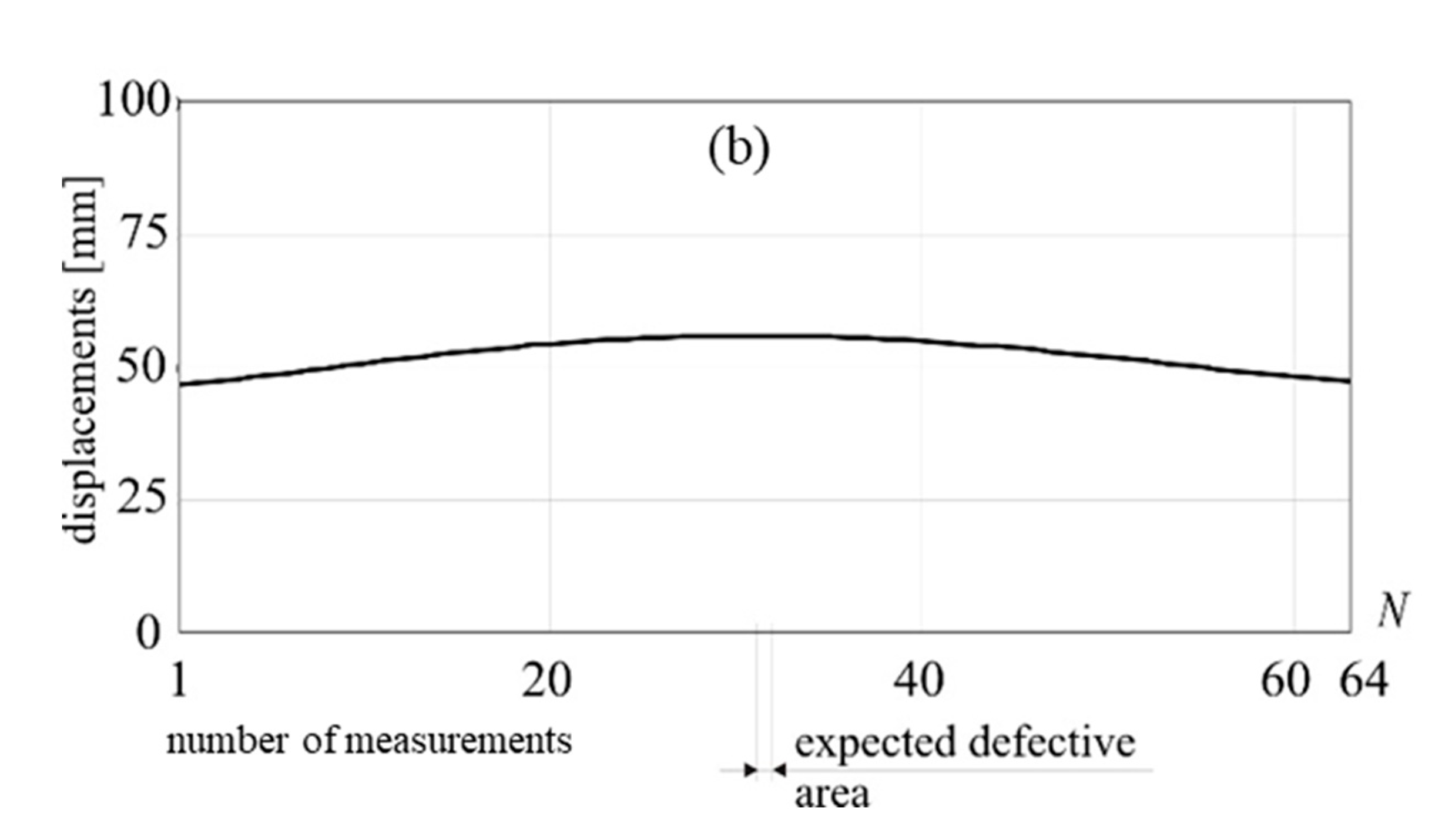
An increase in the tensile strength of the mast cable made it impossible to detect the defective area. Therefore, increasing the stiffness of the entire system, resulting in a decrease in the value of total displacements of selected measurement point (see
Figure 17 a,b), makes the proposed method less effective for detecting damage.
3.4. Case 4 – Variable Location of Damage
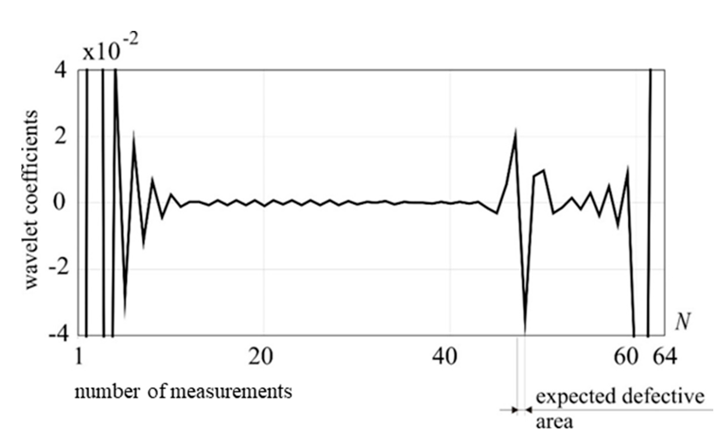
In order to additionally verify the calculations, two examples were considered in which the cable damage is introduced asymmetrically in relation to its length. First, let the weakening of the cable cross-section be introduced in 1/4 of its length, counting from its fixing in the foundation. The loading force of 5 kN is applied identically as in the previous examples, and the cable cross-sectional area has been reduced by 25%. The weakening of the cable cross-section takes place over a distance of 10 cm. The measuring point is placed at the end of the cable, where the guy is connected with the mast. The number of measurements is the same as in previous examples (
N = 64). The results of DWT for Daubechies 6 family of wavelets are presented in
Figure 18, where observable disturbance of the transformed signal is an indicator of the defect presence.
In the second approach, an asymmetrical weakening of the cross-section was introduced at a distance of 1/4 from the point of connection of the cable with the mast. The results of DWT are presented in
Figure 19, where observable disturbance of the transformed signal is similar to the previous one.
Figure 1.
The two-node finite element used for description of the antenna mast [
22].
Figure 1.
The two-node finite element used for description of the antenna mast [
22].
Figure 2.
The two-node finite element used for description of the guy (cable) [
23].
Figure 2.
The two-node finite element used for description of the guy (cable) [
23].
Figure 3.
Analyzed truss steel guyed mast: (a) location of damage and measurement point; (b) view from the top; (c) cross-sections of the bars.
Figure 3.
Analyzed truss steel guyed mast: (a) location of damage and measurement point; (b) view from the top; (c) cross-sections of the bars.
Figure 4.
1-D DWT of utot, Daubechies 12 (D1), external load: 100 kN, damage: 50% reduction of cross section.
Figure 4.
1-D DWT of utot, Daubechies 12 (D1), external load: 100 kN, damage: 50% reduction of cross section.
Figure 5.
1-D DWT of utot, Daubechies 8 (D1), external load: 25 kN, damage: 50% reduction of cross section.
Figure 5.
1-D DWT of utot, Daubechies 8 (D1), external load: 25 kN, damage: 50% reduction of cross section.
Figure 6.
1-D DWT of utot, Daubechies 8 (D1), external load: 50 kN, damage: 50% reduction of cross section.
Figure 6.
1-D DWT of utot, Daubechies 8 (D1), external load: 50 kN, damage: 50% reduction of cross section.
Figure 7.
1-D DWT of utot, Daubechies 8 (D1), external load: 5 kN, damage: 50% reduction of cross section.
Figure 7.
1-D DWT of utot, Daubechies 8 (D1), external load: 5 kN, damage: 50% reduction of cross section.
Figure 8.
1-D DWT of utot, Daubechies 6 (D1), external load: 1 kN, damage: 50% reduction of cross section.
Figure 8.
1-D DWT of utot, Daubechies 6 (D1), external load: 1 kN, damage: 50% reduction of cross section.
Figure 9.
1-D DWT of utot, Daubechies 8 (D1), external load: 1 kN, damage: 50% reduction of cross section.
Figure 9.
1-D DWT of utot, Daubechies 8 (D1), external load: 1 kN, damage: 50% reduction of cross section.
Figure 10.
1-D DWT of utot, Daubechies 8 (D1), external load: 5 kN, damage: 25% reduction of cross section.
Figure 10.
1-D DWT of utot, Daubechies 8 (D1), external load: 5 kN, damage: 25% reduction of cross section.
Figure 11.
1-D DWT of utot, Daubechies 6 (D1), external load: 5 kN, damage: 25% reduction of cross section.
Figure 11.
1-D DWT of utot, Daubechies 6 (D1), external load: 5 kN, damage: 25% reduction of cross section.
Figure 12.
1-D DWT of utot, Daubechies 4 (D1), external load: 5 kN, damage: 25% reduction of cross section.
Figure 12.
1-D DWT of utot, Daubechies 4 (D1), external load: 5 kN, damage: 25% reduction of cross section.
Figure 13.
1-D DWT of utot, Daubechies 6 (D1), external load: 5 kN, damage: 10% reduction of cross section.
Figure 13.
1-D DWT of utot, Daubechies 6 (D1), external load: 5 kN, damage: 10% reduction of cross section.
Figure 14.
1-D DWT of utot, Daubechies 6 (D1), external load: 5 kN, damage: 25% reduction of cross section, tension force in a guy cable: 150 kN.
Figure 14.
1-D DWT of utot, Daubechies 6 (D1), external load: 5 kN, damage: 25% reduction of cross section, tension force in a guy cable: 150 kN.
Figure 15.
1-D DWT of the total displacements, Daubechies 6 (detail 1), external load: 5 kN, damage: 25% reduction of cross section, tension force in a guy cable: 200 kN.
Figure 15.
1-D DWT of the total displacements, Daubechies 6 (detail 1), external load: 5 kN, damage: 25% reduction of cross section, tension force in a guy cable: 200 kN.
Figure 16.
1-D DWT of the total displacements, Daubechies 8 (detail 1), external load: 5 kN, damage: 25% reduction of cross section, tension force in a guy cable: 200 kN.
Figure 16.
1-D DWT of the total displacements, Daubechies 8 (detail 1), external load: 5 kN, damage: 25% reduction of cross section, tension force in a guy cable: 200 kN.
Figure 17.
Total displacements of the measurement point, damage 25% reduction of cross-section: (a) tension force in a guy cable 150 kN; (b) tension force in a guy cable 200 kN.
Figure 17.
Total displacements of the measurement point, damage 25% reduction of cross-section: (a) tension force in a guy cable 150 kN; (b) tension force in a guy cable 200 kN.
Figure 18.
1-D DWT of utot, Daubechies 6 (D1), external load: 5 kN, damage: 25% reduction of cross-section in a lower part of the guy cable.
Figure 18.
1-D DWT of utot, Daubechies 6 (D1), external load: 5 kN, damage: 25% reduction of cross-section in a lower part of the guy cable.
Figure 19.
1-D DWT of utot, Daubechies 6 (D1), external load: 5 kN, damage: 25% reduction of cross-section in an upper part of the guy cable.
Figure 19.
1-D DWT of utot, Daubechies 6 (D1), external load: 5 kN, damage: 25% reduction of cross-section in an upper part of the guy cable.
Table 1.
Change in wavelet coefficients’ range with respect to the external loading force value.
Table 1.
Change in wavelet coefficients’ range with respect to the external loading force value.
| External loading force [kN] |
Wavelets coefficients’ range [–] |
| 25 |
<–0.02 to 0.02> |
| 50 |
<–0.04 to 0.04> |
| 100 |
<–0.08 to 0.08> |
| 150 |
<–0.12 to 0.12> |
