1. Introduction
Understanding the in-cylinder flows of a C.I engine is crucial for researchers and scientists, as it directly influences the engine's design and performance. Particularly, the flow structure created by intake flows plays a significant role. Generating high turbulence intensity is vital for ensuring stable combustion. To achieve this efficiently, two types of vertices are commonly employed, which effectively promote and sustain turbulence flows swirl and tumble flows, play a key role in enhancing engine performance. Swirl flow refers to the organized rotation in the horizontal plane of the engine cylinder, while tumble flow involves rotation in the vertical plane. These flows greatly contribute to improved engine performance by enhancing the mixing of fuel and induced air within the cylinder. By promoting better mixing, swirl and tumble flows help optimize combustion efficiency, leading to enhanced power output and fuel economy.
Indeed, visualizing in-cylinder flows in reciprocating engines is a challenging task due to their highly complex nature. Experimental techniques such as hot wire anemometer and laser Doppler velocimetry have been utilized to measure velocity fields. However, the intricate three-dimensional structure, turbulence, and unsteadiness of in-cylinder flows make these measurements quite difficult. The complex interactions between fuel, air, and combustion processes within the engine cylinder create a dynamic environment that is challenging to capture accurately. Researchers face the task of dealing with the constantly changing flow patterns and turbulence, which requires sophisticated measurement techniques and data analysis. Despite the challenges, these experimental works are crucial for gaining insights into in-cylinder flows, as they provide valuable information for optimizing engine design and performance.
When it comes to computational fluid dynamics (CFD) models, it is crucial to address specific challenges related to turbulent flow, high Reynolds number, compressible flow, and complex geometry. The finite volume method (FVM) is one of the most commonly used mathematical models in CFD. It allows for the accurate representation of fluid flow patterns and their interactions. In the context of your investigation, the focus is on simulating the tumble motion, which is a typical fluid flow pattern observed in automotive engines. To accurately capture the complex flow behavior, the RNG k-e turbulence model is employed in the CFD simulations. This model helps simulate turbulent flows, taking into account the effects of turbulent eddies and their interactions. By using these techniques, researchers can gain valuable insights into the behavior of in-cylinder flows and their impact on engine performance.
1.1. Flow Patterns
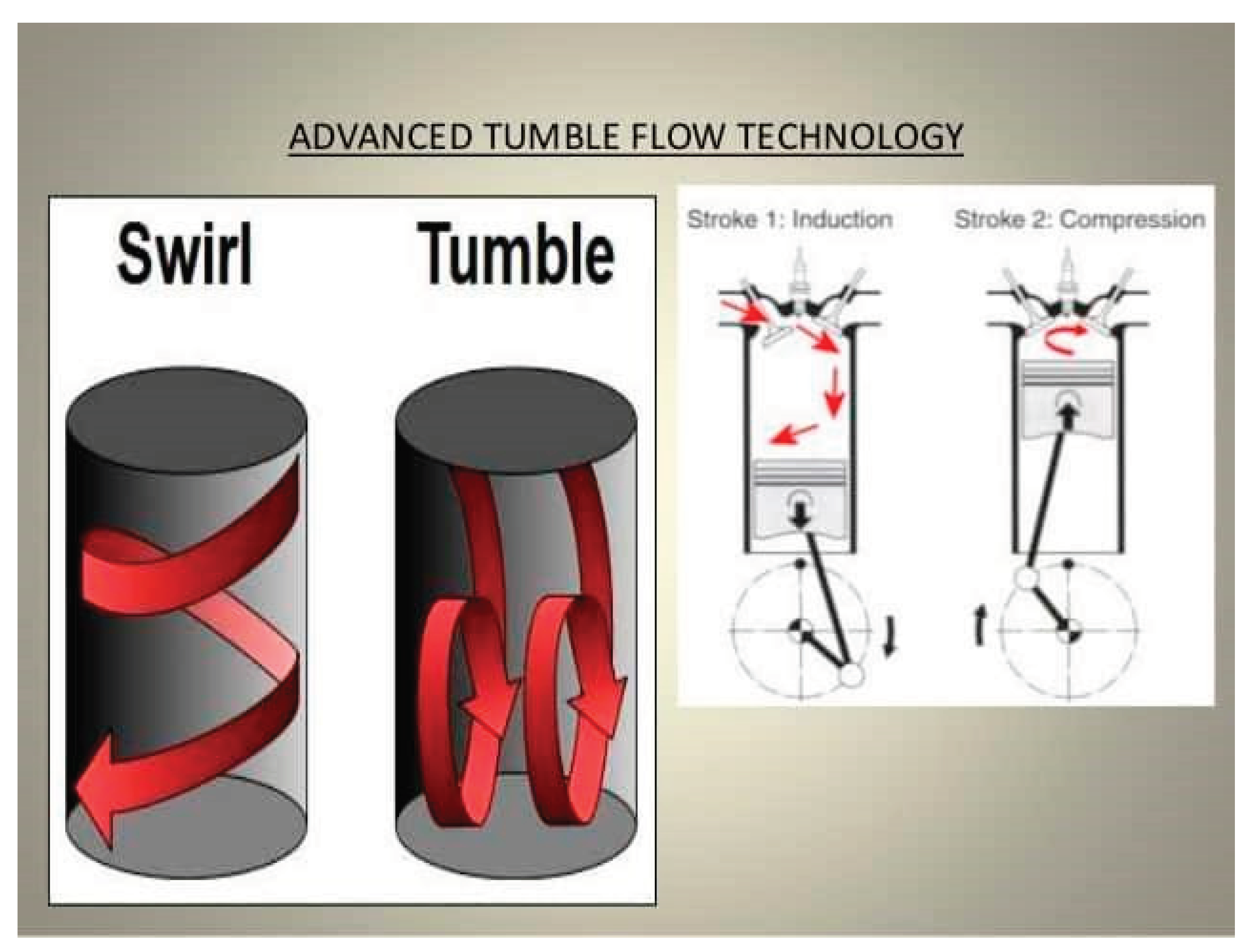
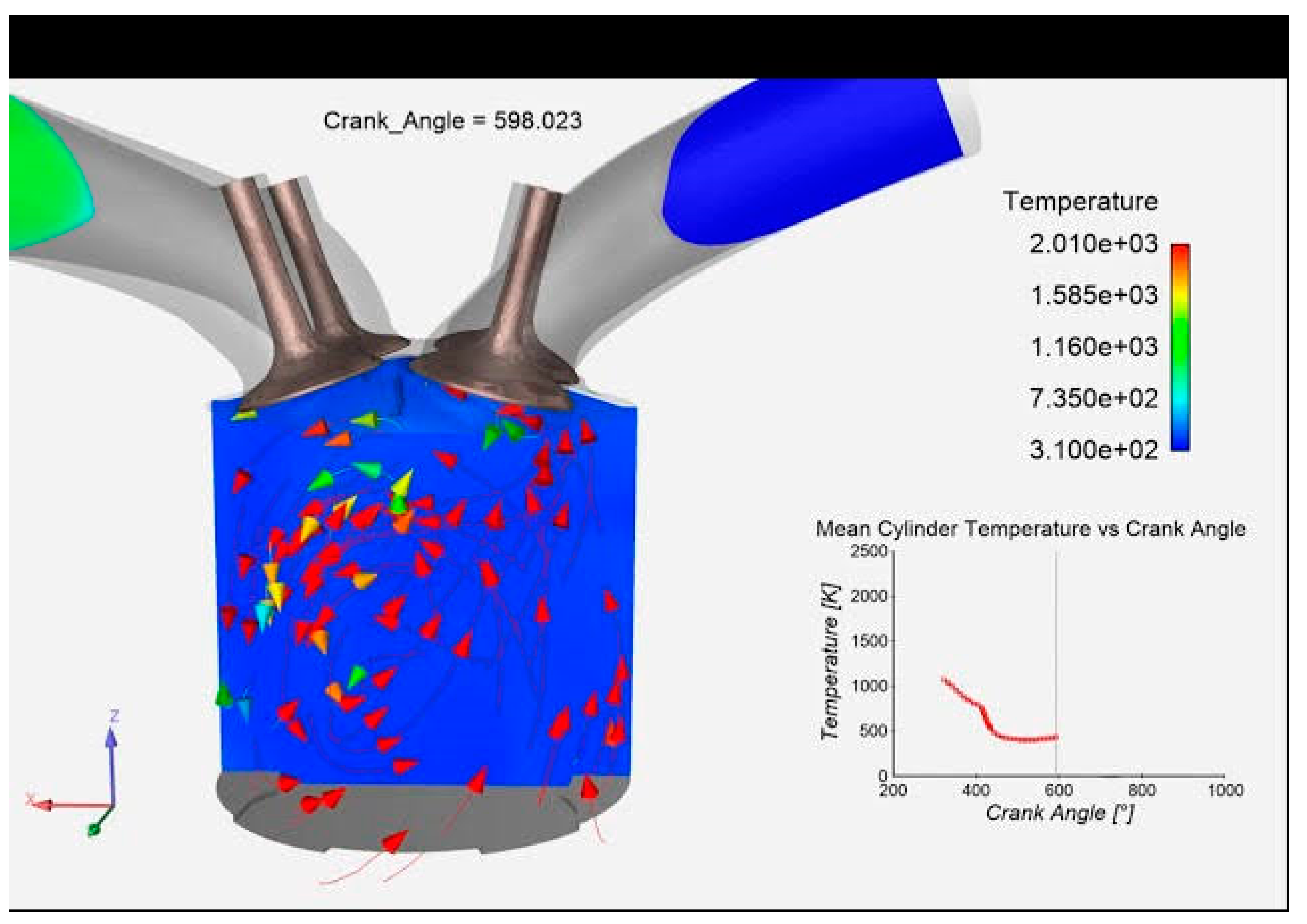
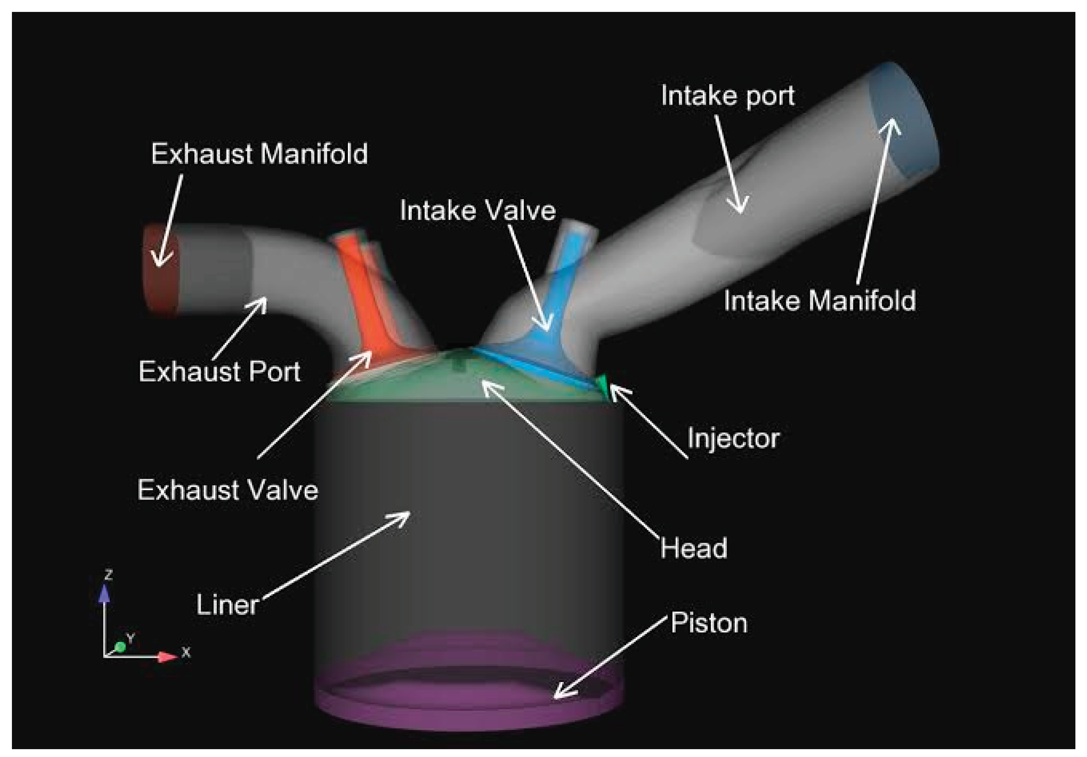
Swirl, a term used to describe the organized rotation of electric charge around the axis of a cylinder, plays a crucial role in various applications. In the realm of diesel engines, swirl is intentionally generated by imparting an initial angular momentum to the intake flow entering the cylinder. This deliberate creation of swirl serves a dual purpose: enhancing the efficiency of the mixing process between the inducted air charge and the injected fuel, and expediting the combustion process itself. To illustrate this concept, please refer to the visual representation of the swirl motion inside the engine cylinder depicted in
Figure 1.
Tumble refers to the rotational motion around a circumferential axis near the edge of the clearance volume in the cylinder head. This motion is a result of the compression of the in-cylinder volume when the rotor approaches near top dead center (TDC). The values for tumble can be calculated by dividing the effective angular speed of the in-cylinder air motion by the engine speed. The effective angular speed, in turn, is determined by the ratio of the angular momentum to the angular inertia of the moment. To get a better visual understanding of this tumble motion, please refer to
Figure 1, which illustrates the internal motion inside the engine cylinder.
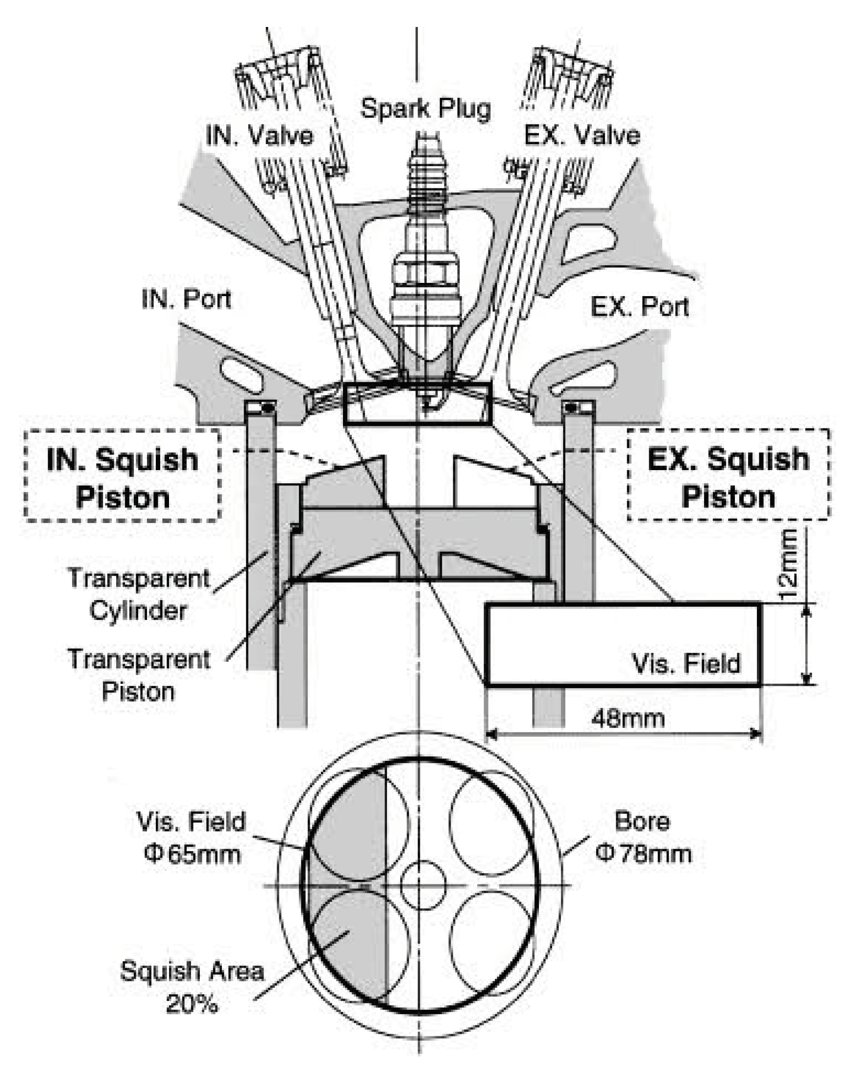
Squish refers to the gas motion that occurs during the latter part of the compression stroke, where the gas is forced inward or transversely. This squish-generated gas motion is achieved by employing a compact combustion chamber design. In the context of a bowl-in-rotor direct-injection diesel combustion chamber,
Figure 2 demonstrates how the motion of the rotor generates the squish effect. This design feature enhances the efficiency and effectiveness of the combustion process.
1.2. Objective of the Study
- ➢
To perform modeling, meshing, and flow analysis of a multi-chamber rotor C.I engine and base engine in computational fluid dynamics (CFD), you can follow these steps
- ➢
1. Start by creating a 3D model of the multi-chamber rotor C.I engine and the base engine, ensuring that all the necessary details and components are included.
- ➢
2. Once the model is ready, proceed to meshing, where the computational domain is divided into small elements or cells to enable accurate flow analysis. Generate a high-quality mesh that captures the intricate features and boundaries of the engine geometry.
- ➢
3. With the mesh in place, set up the appropriate boundary conditions and define the operating parameters for the simulation, such as inlet conditions, fuel injection strategy, and combustion model
- ➢
4. Run the CFD simulation, which will solve the governing equations of fluid dynamics to predict the flow patterns, turbulence, and combustion characteristics within the engine.
- ➢
5. Post-process and analyze the results obtained from the simulation, examining parameters such as velocity profiles, pressure distribution, temperature distribution, and emissions. By performing this modeling, meshing, and flow analysis using CFD, you can gain valuable insights into the performance and behavior of the multi-chamber rotor C.I engine and the base engine
1.3. Overview of Diesel Engine
A Diesel engine is indeed an internal combustion engine that operates using the Diesel cycle. It was invented by the German engineer Rudolf Diesel in 1892, and he obtained a patent for it on February 23, 1893. In a Diesel engine, the fuel is injected into a combustion chamber that contains highly compressed air. Unlike in gasoline engines where the fuel-air mixture is ignited by a spark plug, in a Diesel engine, the fuel ignites due to the high temperature and pressure of the compressed air. This process is known as compression ignition. The combustion of the fuel releases energy, which drives the piston and generates power. Diesel engines are known for their efficiency, durability, and excellent torque output, making them popular in various applications such as automobiles, trucks, ships, and generators.
1.4. How Diesel Engine Works
In mechanical terms, the internal construction of a Diesel engine does share similarities with its gasoline counterpart. Components such as rotors, connecting rods, and a crankshaft can be found in both types of engines. Similar to a gasoline engine, a Diesel engine can operate on a four-stroke cycle, which is similar to the Otto cycle used in gasoline engines. Alternatively, it can also operate on a two-stroke cycle. However, the key differences between the two lie in the handling of air and fuel, as well as the combustion process. One major distinction is the handling of air and fuel. In a Diesel engine, air is drawn into the combustion chamber during the intake stroke, and only air is compressed during the compression stroke. Fuel is injected into the chamber at the end of the compression stroke, mixing with the highly compressed air. Regarding the combustion process, in a gasoline engine, the fuel-air mixture is ignited by a spark plug. In a Diesel engine, the fuel ignites due to the high temperature and pressure resulting from the compression of the air-fuel mixture. These differences in air and fuel handling, as well as combustion methods, contribute to the distinct characteristics and performance of Diesel engines, such as their high torque output and fuel efficiency.
In a Diesel engine, compression combustion is used to ignite the fuel, eliminating the need for a spark plug like in gasoline engines. When air is compressed to a high degree, its temperature rises to a point where the injected fuel spontaneously ignites upon contact. This principle of high compression and temperature is employed in both four-stroke and two-stroke Diesel engines to generate power. The compression ratio in Diesel engines typically ranges from 16:1 to 25:1, which means that the volume of the air-fuel mixture is compressed to a fraction of its original size. As a result of this intense compression, the temperature of the air rises significantly, reaching temperatures between 700 to 900 degrees Celsius (1300 to 1650 degrees Fahrenheit). This high temperature, combined with the injection of fuel into the compressed air, leads to combustion and the release of energy that powers the engine. The reliance on compression combustion in Diesel engines contributes to their distinctive characteristics, such as their efficiency, high torque output, and suitability for heavy-duty applications. If Fuel oil is introduced into the cylinder at high pressure, resulting in the atomization of the fuel charge. Due to the elevated temperature of the air within the cylinder, combustion takes place almost instantaneously. As a result, there is a rapid and significant rise in both cylinder temperature and pressure. This process facilitates efficient and effective combustion, contributing to the overall performance of the system..
1.5. P-V & T-S Diagram Of C.I Engine Cycle
The cycle we're discussing was originally developed by Rudolph Diesel and is commonly used in slow-speed compression combustion engines, also known as diesel engines. It is referred to as a constant pressure cycle because heat is added at a constant pressure. This cycle is made up of two reversible adiabatic processes, one constant pressure process, and one constant volume process. By adhering to these principles, we can create a unique and efficient engine design.
The PV diagram depicted in
Figure 3 illustrates various processes. These include: 1-2: This represents the adiabatic compression process, where the volume decreases while no heat is exchanged with the surroundings. 2-3: It signifies the constant pressure process, where the volume remains constant while heat is added to the system. 3-4: This represents the adiabatic expansion process, where the volume increases while no heat is exchanged with the surroundings. 4-1: It signifies a drop in pressure at constant volume, where the volume remains constant while the pressure decreases. These processes exhibit the different stages of the cycle, each playing a crucial role in the overall functioning of the system. The PV diagram helps visualize and understand these processes better.
2. Different Types of Combustion Chambers in Ci Engine
In larger-sized engines, where stringent mixing rate requirements are not as crucial, a quiescent direct injection system, as depicted in
Figure 4A, is commonly employed. This system relies on the momentum and energy of the injected fuel jets to achieve sufficient fuel distribution and promote effective mixing with the air. There is no need for additional organized air motion to enhance the process. Typically, the combustion chamber in these engines is designed with a shallow bowl shape in the crown of the rotor, and a central multi-hole injector is utilized. This configuration allows for optimal fuel injection and combustion performance. However, as engine size decreases, it becomes increasingly important to introduce air swirl into the combustion chamber. This is done to enhance the mixing process and ensure efficient combustion. The swirl helps create a more uniform air-fuel mixture, leading to improved combustion performance and overall engine efficiency.
To achieve faster fuel-air mixing rates in smaller-sized engines, air swirl is generated through the appropriate design of the inlet port. By designing the inlet port in a way that guides the air towards the cylinder axis, the swirl rates can be increased as the rotor approaches top dead center (TDC). This is especially effective when coupled with a bowl-in-rotor type of combustion chamber, as depicted in
Figure 3.2B[
8]. The unique design of the combustion chamber promotes the generation of a swirling motion in the incoming air, resulting in a more efficient mixing of fuel and air. This enhanced mixing leads to improved combustion and overall engine performance. By utilizing this design approach, engineers can optimize the fuel-air mixture in smaller engines, ensuring efficient combustion and maximizing the engine's capabilities.
The research mentioned in this study aligns with several United Nations Sustainable Development Goals (SDGs). The primary goal that it addresses is
SDG 7: Affordable and Clean Energy. By exploring the optimization of fuel burning efficiency in existing systems and enhancing the performance of compression ignition (C.I) engines, the research contributes to the development of more sustainable and environmentally-friendly power generation methods. Additionally, the findings from this study can also support
SDG 9: Industry, Innovation, and Infrastructure. By investigating the effects of combustion chamber geometry on fluid flow characteristics and utilizing advanced simulation techniques, the research drives innovation in engine design and development. This contributes to the improvement of industry practices and infrastructure in the field of combustion engines. Furthermore, the research indirectly supports
SDG 13: Climate Action by aiming to enhance fuel efficiency and reduce emissions in C.I engines. Improving the combustibility of fuel-air mixtures can lead to reduced greenhouse gas emissions and contribute to mitigating climate change. Overall, the research aligns with the United Nations Sustainable Development Goals by addressing energy affordability, promoting innovation, and working towards climate action. By focusing on optimizing combustion engines, it contributes to creating a greener and more sustainable future.
SIGNIFICANT
The research mentioned in this study holds significant importance in several ways.
Firstly, it addresses the pressing global issue of increasing demand and scarcity of fossil fuels. By exploring effective fuel burning and enhancing combustion efficiency, the research contributes to finding solutions for sustainable energy utilization and reducing dependence on finite resources.
Secondly, by investigating the effects of combustion chamber geometry on fluid flow characteristics, the research aims to optimize engine design for improved performance. This has practical implications for industries that heavily rely on compression ignition (C.I) engines, such as automotive and power generation sectors. Enhanced engine efficiency translates to reduced fuel consumption, lower emissions, and cost savings for businesses and consumers alike.
Thirdly, the research utilizes advanced simulation techniques and computational fluid dynamics (CFD) analysis, highlighting the significance of technological innovations in engine design and development. By leveraging these tools, researchers gain valuable insights into the complex fluid dynamics within the combustion chamber, leading to further advancements in the field.
Lastly, the research aligns with the United Nations Sustainable Development Goals (SDGs), particularly
SDG 7 (Affordable and Clean Energy), SDG 9 (Industry, Innovation, and Infrastructure), and indirectly SDG 13 (Climate Action). By contributing to energy affordability, promoting innovation in the industry, and mitigating climate change through reduced emissions, the research addresses key sustainability challenges. The significance of this research lies in its potential to revolutionize power generation, improve engine performance, and contribute to a greener and more sustainable future.
2.1. Introduction to CFD
Fluid dynamics is a branch of physics that focuses on the study of the dynamic behavior of fluids, such as liquids and gases. It involves analyzing how fluids move, interact, and respond to various forces and conditions. Computational Fluid Dynamics (CFD) is a mathematical interpretation and computational technology used to simulate and analyze fluid flow and its related phenomena. By utilizing numerical methods and algorithms, CFD allows us to solve the complex sets of partial differential equations that govern fluid dynamics. These equations are often challenging to solve analytically, making CFD an invaluable tool for researchers and engineers. With CFD, we can virtually model and study the dynamics of things that flow, such as airflow around an airplane wing, water flow in a pipe, or combustion processes in an engine. It provides valuable insights into fluid behavior, allowing for optimization, design improvements, and performance prediction S
The physical aspects of fluid flow are indeed governed by three fundamental principles: conservation of mass, Newton's second law, and conservation of energy. These principles form the basis for understanding and analyzing fluid dynamics. Conservation of mass states that the total mass of a fluid remains constant within a closed system, meaning that mass cannot be created or destroyed during the flow process. Newton's second law, also known as the momentum equation, describes the relationship between the forces acting on a fluid and the resulting acceleration. It states that the rate of change of momentum of a fluid is equal to the net force acting on it. Conservation of energy, also known as the energy equation, states that the total energy of a fluid remains constant, accounting for both the potential and kinetic energy changes within the system. Computational Fluid Dynamics (CFD) is the field of science that involves solving the mathematical equations derived from these fundamental principles to obtain a numerical solution. By discretizing the governing equations using numerical methods, CFD allows us to simulate and analyze fluid flow behavior under various conditions, providing valuable insights into complex fluid phenomena.
Computational Fluid Dynamics (CFD) plays a crucial role in providing qualitative and sometimes quantitative predictions of fluid flows. It achieves this by utilizing mathematical modeling, which involves expressing the governing partial differential equations that describe fluid behavior. The mathematical models are then solved using various discretization and solution techniques to obtain numerical solutions. CFD software tools, including solvers, pre-processing utilities, and post-processing tools, assist in carrying out these simulations effectively. By conducting these "mathematical model experiments" or computer simulations, CFD enables scientists and engineers to create a virtual flow laboratory. This virtual environment allows them to study and analyze fluid flows under different conditions without the need for costly and time-consuming physical experiments. Through CFD simulations, researchers can gain valuable insights into the behavior of fluids, explore different design options, optimize performance, and even predict the impact of changes before implementing them in the real world.
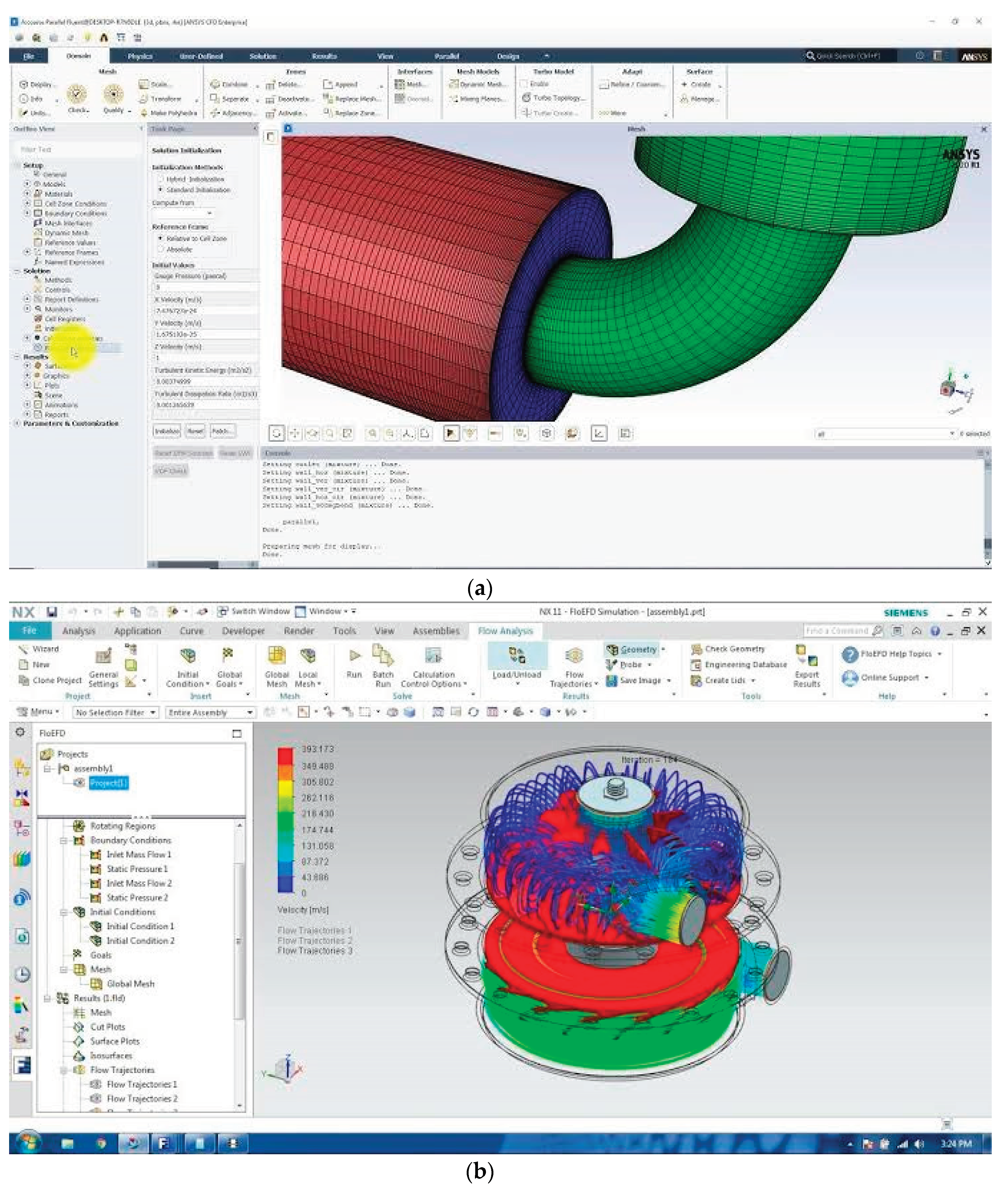
- (1)
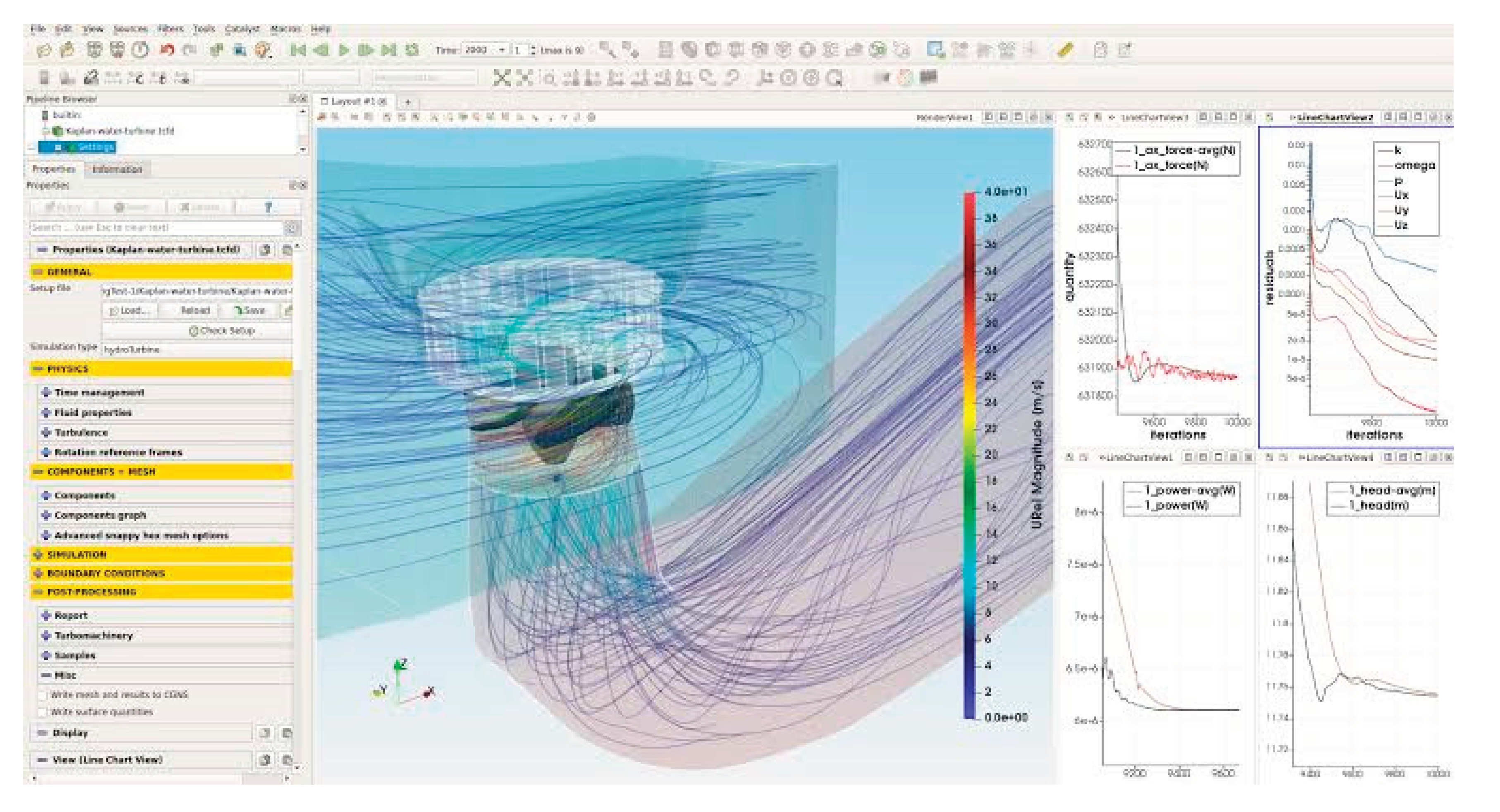
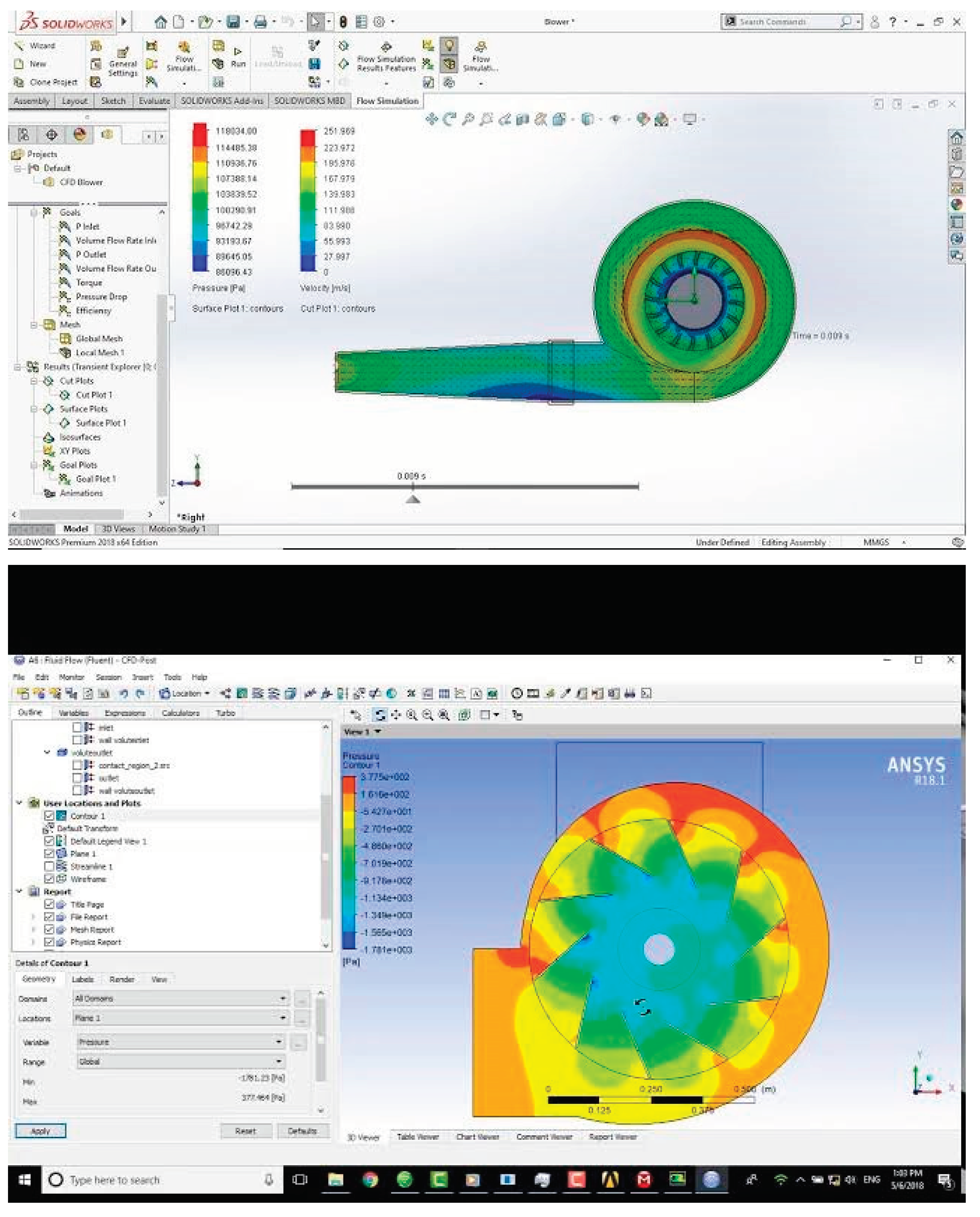
FLUENT, a widely-used computational fluid dynamics (CFD) software, provides various means to obtain and analyze results from fluid flow simulations. FLUENT offers graphic displays that allow users to visualize results in an intuitive and informative manner. Results can be presented through contour plots, which display variables such as pressure, temperature, or velocity as color-coded maps on the computational domain. Velocity vectors can also be plotted to visualize the flow direction and magnitude at different locations. Additionally, particle tracking and path lines can be generated to observe the trajectory and behavior of particles within the flow. In addition to visual representations, FLUENT provides comprehensive reports that offer detailed numerical data and analysis. These reports can include parameters such as mass flow rates, pressure drop, heat transfer coefficients, and many other relevant quantities. This information allows engineers and researchers to evaluate and assess the performance of their designs or systems. Furthermore, FLUENT is equipped with extensive calculation capabilities. Users can perform various calculations within the software to obtain specific insights or investigate particular aspects of the flow. Whether it's computing force coefficients, evaluating turbulence parameters, or conducting heat transfer analyses, FLUENT provides the necessary tools for these calculations. Overall, FLUENT offers a comprehensive platform for obtaining, analyzing, and visualizing results from CFD simulations, empowering users to gain valuable insights and make informed decisions.
In addition to the graphic display and report capabilities, FLUENT allows users to save their simulation results and data for future reference. This is done by writing the files containing the relevant information. FLUENT provides options to save the simulation results in various formats, depending on the specific needs and requirements. These files typically include the solution data, grid information, boundary conditions, and any other relevant parameters. By saving these files, users can easily retrieve and reload their simulation results at a later time. This is particularly useful when performing subsequent analyses, comparing different design scenarios, or sharing the results with colleagues or collaborators. The ability to save and archive the simulation data ensures that valuable information and results are preserved enabling users to revisit and utilize them as needed.
2.2. Governing Equations in CFD
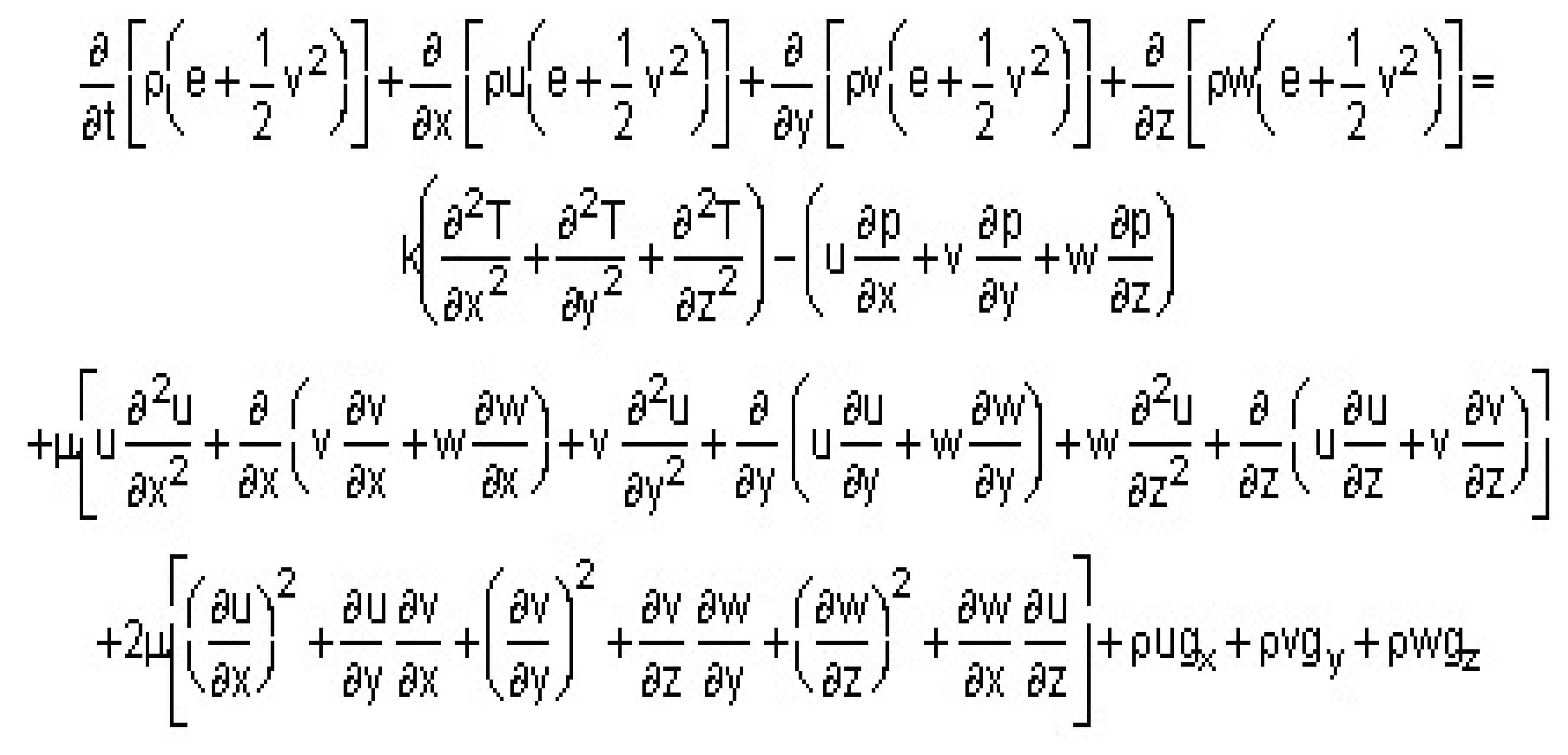
(a) Continuity Equation
The continuity equation, which expresses the principle of mass conservation, can be formulated in either integral or differential form. In integral form, the continuity equation is expressed as: ∮ ρ * v ⋅ dA = 0 where ρ is the density of the fluid, v is the velocity vector, and the integral is taken over a closed surface (A) enclosing a control volume. This equation states that the net mass flow rate into or out of the control volume is zero, ensuring the conservation of mass. On the other hand, the differential form of the continuity equation is written as: ∂ρ/∂t + ∇ ⋅ (ρ * v) = 0 where ∂ρ/∂t represents the rate of change of density with respect to time, and ∇ ⋅ (ρ * v) is the divergence of the mass flux density. This equation states that the net rate of change of mass density within an infinitesimally small control volume, plus the net mass flux across its boundaries, is zero. Both forms of the continuity equation are mathematically equivalent and represent the fundamental principle of mass conservation in fluid dynamics.

statement of the principle of mass conservation for a steady, one-dimensional flow, with one inlet and one outlet: "In the context of a continuous, one-dimensional flow system featuring a single entrance and exit, the principle of mass conservation asserts that the total mass entering the system through the inlet is equal to the total mass exiting through the outlet. This principle remains applicable under stable conditions, where the flow rate and properties of the substance remain constant along the flow path. By upholding mass conservation, we ensure that there is no net gain or loss of mass within the system, guaranteeing a balanced and continuous flow process."
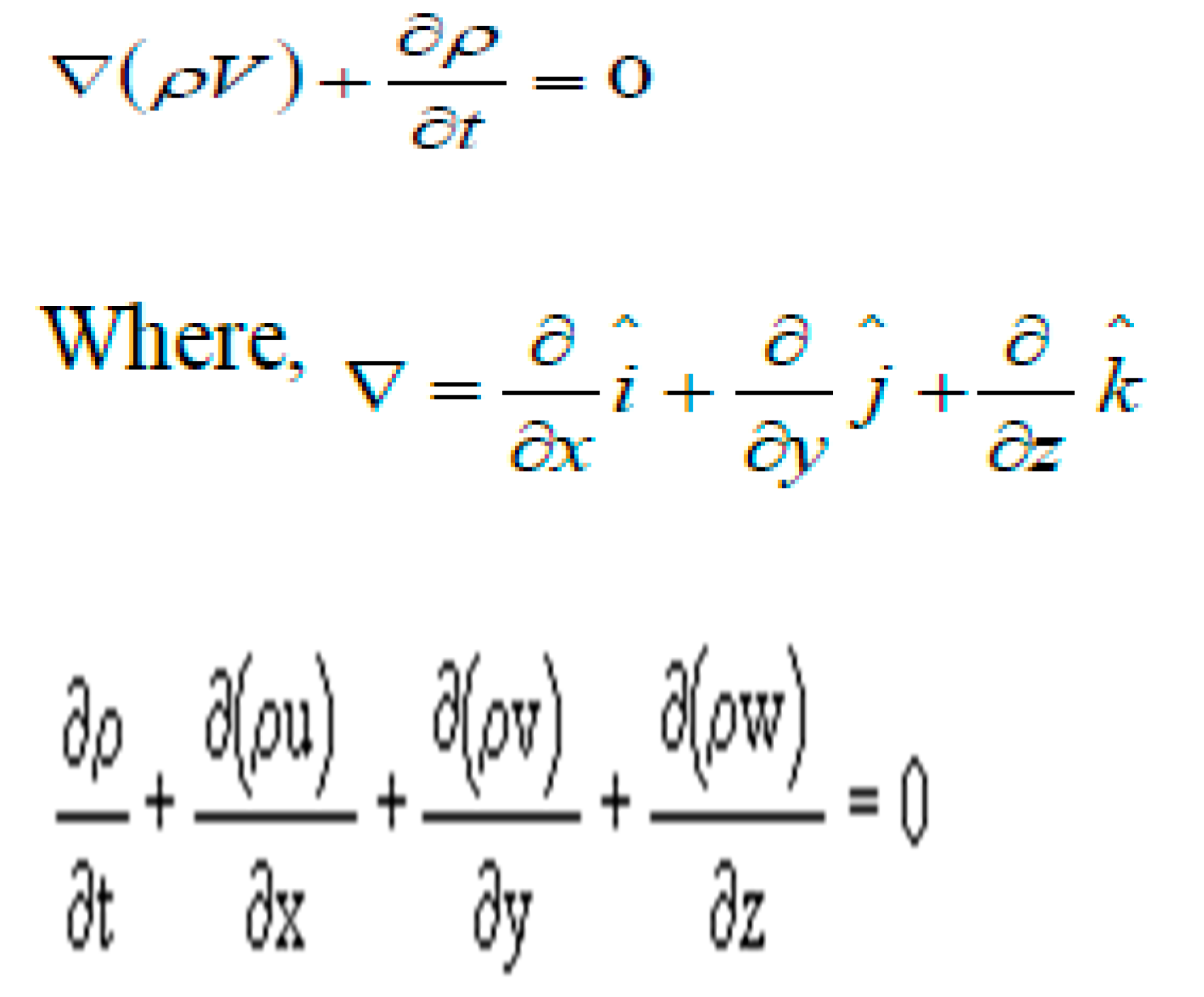
(b) Momentum (Navier Stokes Equations The momentum equation in fluid dynamics is indeed a statement of Newton's Second Law, relating the sum of forces acting on a fluid element to its acceleration or rate of change of momentum. Newton's Second Law states that the force acting on an object is equal to its mass multiplied by its acceleration (F = ma). In the context of fluid dynamics, this law is applied to fluid elements. The momentum equation in fluid dynamics can be expressed as: ∂(ρv)/∂t + ∇ ⋅ (ρvv) = ∇ ⋅ τ + ρg where ρ is the density of the fluid, v is the velocity vector, t represents time, ∇ is the gradient operator, τ is the stress tensor, and g is the gravitational acceleration. This equation states that the rate of change of momentum of a fluid element is equal to the sum of the convective acceleration term (∇ ⋅ (ρvv)), the pressure gradient term (∇ ⋅ τ), and the gravitational force term (ρg). By applying Newton's Second Law to fluid dynamics, the momentum equation provides a fundamental understanding of how forces act on fluid elements and affect their motion
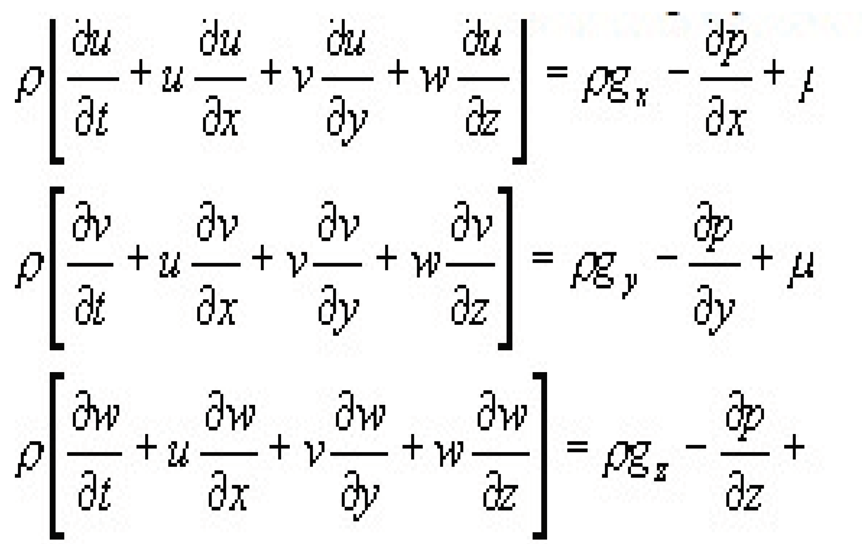
(c) Energy Equation
In scenarios where the fluid can be considered in-compressible and temperature differences are small, the continuity equation and the three momentum equations (x, y, and z directions) are sufficient to determine the velocities and pressure of the flow. This results in a set of four equations and four unknowns (u, v, w, and p). However, in cases where the flow is compressible (density is not constant) or when heat flux occurs (temperature is not constant), at least one additional equation is required to fully describe the flow behavior. This is because in such situations, the effects of density and temperature variations have to be considered. One common additional equation used in these instances is the Energy equation. The Energy equation accounts for the transfer of heat and the associated changes in temperature within the flow. It provides insights into the thermal behavior of the fluid and helps determine temperature distributions. By including the Energy equation along with the continuity equation and the three momentum equations, the necessary set of equations can be formed to determine all the required variables, including velocities, pressure, and temperature. These additional equations ensure a more comprehensive and accurate representation of the flow, particularly in compressible or thermally significant scenarios.
2.3. The Advantages of CFD
CFD offers several compelling reasons for its use:
Insight: CFD analysis provides valuable insights into devices and systems that are challenging or expensive to prototype. It can reveal hidden aspects and phenomena within the system that may not be easily observable through other means. By visualizing and analyzing the flow patterns, CFD enhances the understanding of designs, allowing for informed decision-making and optimization.
Foresight: CFD enables engineers and designers to anticipate and predict the behavior of fluid flows before the physical implementation. By simulating different scenarios and conditions, CFD helps identify potential issues, optimize performance, and make informed design choices. This foresight saves time, reduces costs, and minimizes the need for multiple iterations during the development process.
Efficiency: CFD allows for virtual testing and optimization of designs, reducing the dependency on physical testing and prototyping. This significantly cuts down on the time and resources required for traditional experimental approaches. By analyzing fluid flow behavior and performance virtually, engineers can iteratively refine designs and achieve optimal efficiency in various applications.
Problem-solving: CFD serves as a powerful tool for troubleshooting and problem-solving in fluid dynamics. It helps identify the root causes of issues and provides insights into potential solutions. By simulating different scenarios and analyzing flow behavior, CFD assists in identifying and resolving challenges in fluid flow systems. In summary, CFD offers valuable insights, foresight, efficiency, and problems solving capabilities, making it an indispensable tool for engineers and designers in various industries
2.4. Applications of CFD
When fluids flow with the complications you mentioned, such as simultaneous flow of heat, mass transfer, phase change, chemical reactions, and mechanical movement, along with stresses and displacement of immersed or surrounding solids, CFD becomes an invaluable tool. Here's how CFD can address these complexities:
Simultaneous flow of heat: CFD allows for the analysis of heat transfer within fluid flows by considering conduction, convection, and radiation. It helps predict temperature distributions, heat transfer rates, and thermal performance of systems like heat exchangers, electronics cooling, and HVAC systems.
Overview of Diesel Engine : CFD can accurately simulate the transport of substances within fluid flows, be it through perspiration, dissolution, or other mass transfer processes. It is used to study diffusion, concentration distributions, and the behavior of chemical species in various applications like chemical reactions, pharmaceutical processes, and environmental studies.
Phase change: CFD models can handle phase change phenomena such as melting, freezing, and boiling. By accounting for changes in fluid properties, CFD can predict the behavior of multi-phase flows, including phase fraction, interface dynamics, and heat transfer during phase transitions, which is vital in areas like cryogenics, refrigeration, and energy systems.
Chemical movement reaction:CFD can incorporate chemical reaction models to predict reaction rates, species concentrations, and reaction products. It is used in combustion analysis, chemical processing, and environmental pollutant studies to understand and optimize chemical reactions within fluid flows.
Mechanical movement: CFD can simulate the interaction between fluid flow and mechanical components like rotors, fans, and rudders. This helps in analyzing forces, torque, and fluid-induced stresses on the solids, aiding in the design and optimization of mechanical systems.
Stresses and displacement of solids: CFD can couple with structural analysis methods to consider the interaction between fluid flow and the immersed or surrounding solids. This helps in understanding the impact of fluid-induced forces, pressures, and thermal effects on the structural behavior and integrity of components and systems. By incorporating these complexities into CFD simulations, engineers and scientists can gain valuable insights, optimize designs, and solve problems in a wide range of applications.
2.5. Limitations of CFD
CFD-based predictions may not always be 100% reliable due to several reasons, including:
Input data uncertainty: The accuracy and reliability of CFD predictions heavily depend on the quality and accuracy of the input data. Uncertainties in boundary conditions, initial conditions, material properties, and other inputs can impact the reliability of the predictions.
Limited computer power: The complexity and accuracy of mathematical models used in CFD simulations can require significant computational resources. Limited computer power may restrict the level of detail and accuracy achievable in the simulations, potentially affecting the reliability of the predictions.
Laminar vs. turbulent flows: CFD simulations for laminar flows, which are smooth and orderly, are generally more accurate and reliable compared to turbulent flows, which are characterized by chaotic and unpredictable behavior. Turbulence modeling introduces additional complexities and uncertainties that can impact the reliability of the predictions.
Single-phase vs. multi-phase flows: CFD simulations for single-phase flows, where only one fluid is involved, are typically more reliable compared to multi-phase flows, which involve the interaction of multiple fluid phases. The complexities associated with interface dynamics, phase change, and interaction between different phases introduce additional uncertainties that can affect the reliability of the predictions.
Chemically inert vs. chemically reactive materials: CFD simulations for chemically inert materials are generally more reliable compared to simulations involving chemically reactive materials. Chemical reactions introduce additional complexities and uncertainties, such as reaction rates, species transport, and heat release, which can impact the accuracy and reliability of the predictions.
Single vs. multiple chemical reactions and complex composition: CFD simulations for single chemical reactions with well-defined composition are typically more reliable than simulations involving multiple chemical reactions or complex compositions. The interactions between multiple reactions and complex compositions introduce additional challenges and uncertainties, affecting the reliability of the predictions. It's important to acknowledge these limitations and uncertainties in CFD simulations and exercise caution when interpreting and relying on the results. CFD should be used as a valuable tool for design insights and optimization, but physical validation and experimental data are often necessary to ensure the reliability of the predictions.
3. Modeling and Meshing
This combination of software tools is commonly used in the field of engineering and allows for efficient and accurate modeling and meshing of complex geometries. CATIA provides a robust platform for creating 3D models, enabling you to design and represent the geometry of the CI engine and its multi-chamber rotor. With its broad range of features and capabilities, CATIA allows for precise and detailed modeling, ensuring that the geometry accurately reflects the physical system. Once the modeling is complete, the next step is meshing, which involves dividing the geometry into small elements or cells to create a mesh. This process is crucial for accurate simulation and analysis. HYPERMESH, a powerful meshing tool, is widely used for generating high-quality meshes with the desired level of refinement and accuracy. By using CATIA for modeling and HYPERMESH for meshing, you have taken important steps in preparing your geometry for subsequent analysis and simulations.
Figure 5.
Two-dimensional view multi -chamber rotor of CI engine.
Figure 5.
Two-dimensional view multi -chamber rotor of CI engine.
Table 1.
Engine specification.
Table 1.
Engine specification.
SL
NO |
ENGINE
PARAMETERS |
SPECIFICATION |
| 01 |
Engine Type |
TV1(kirloskar, four stroke) |
| 02 |
Number of Cylinders |
Single cylinder |
| 03 |
Number of strokes |
Four-stroke |
| 04 |
Rated power |
5.2KW(7HP) @ 1500rpm |
| 05 |
Bore |
87.5 |
| 06 |
Stroke |
110mm |
| 07 |
Cubic Capacity |
661cc |
| 08 |
Compression ratio |
17.5:1 |
| 09 |
Rated speed |
1500 rpm |
| 10 |
Dynamometer |
Eddy current dynamometer, make SAJ |
| 11 |
Type of cooling |
Water cooling |
| 12 |
Fuel injection pressure |
190 Bar |
| 13 |
Fuel |
Diesel |
3. Geometric Model Creation
That's an insightful description of the top-down approach in creating the computational domain! In the top-down approach, the computational domain is constructed by applying logical operations to primitive shapes. This method allows for the creation of complex geometries by combining and manipulating basic shapes. To create the geometry, you can use the same pre-processor software that is used to generate the grid, or you can utilize other programs like computer-aided design (CAD) or graphics software. These tools provide a range of functionalities to model and manipulate geometries accurately. Once the geometry is created, it can be imported into HYPERMESH (HM), where the computational domain is defined. HM offers efficient tools to extract the fluid domain from the imported geometry, enabling the creation of the computational domain specific to the CI engine analysis. By using the top-down approach and leveraging software like CAD, graphics programs, and HM, you can accurately create the computational domain for your CI engine analysis.
Figure 6.
CFD Model of computational domain.
Figure 6.
CFD Model of computational domain.
The
Figure 7 shows the CFD Model computational domain which is done by using CATIA and it is then extracted for meshing and analysis.
Figure 7.
Isometric View of Computational Domain.
Figure 7.
Isometric View of Computational Domain.
The isometric view of the computational domain, as shown in
Figure 7, gives a clear representation of the multiple compartment rotor in sectional views. This visualization helps in understanding the geometry and layout of the rotor within the computational domain. Once the rotor geometry is defined, it is then meshed using HYPERMESH. The meshing process involves dividing the rotor geometry into small elements or cells. It is important to use appropriate elements or cells that suit the characteristics and requirements of the analysis being performed. HYPERMESH offers a range of meshing options and techniques to create high-quality meshes. By utilizing the appropriate meshing elements and parameters, you can ensure that the mesh accurately represents the rotor geometry and captures the necessary detail for accurate analysis. The resulting mesh serves as the foundation for subsequent simulations and analysis of the CI engine, enabling a better understanding of flow behavior, heat transfer, and other important phenomena.
3.1. Geometry Decomposition-Mesh Generation
In Fluent 6.3, two different methods are utilized to solve in-cylinder problems: the hybrid approach and the layering approach. The hybrid approach specifically caters to engines with canted valves. The process of using Fluent involves three stages. The first stage involves decomposing the geometry into distinct zones and ensuring a proper meshing for each zone. This allows for the application of different mesh motion strategies for various regions within a single simulation.
In the second stage of the process, Fluent is used to set up the engine case by utilizing a setup journal. This journal assists in configuring the necessary parameters for the simulation. Moving on to the third stage, a transient in-cylinder simulation is performed to analyze the behavior of the system over time. To illustrate the decomposition process, you can refer to
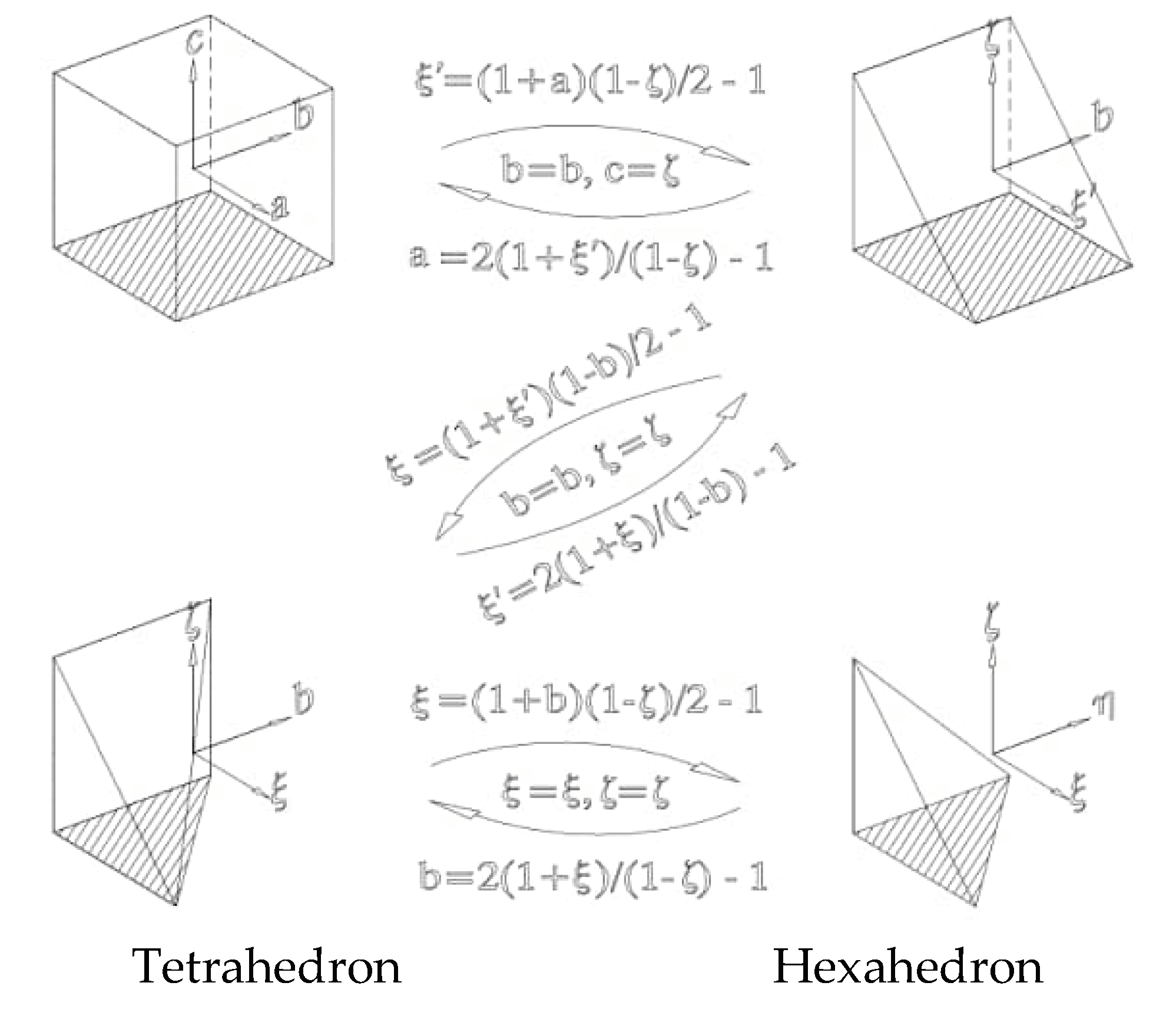
Figure 9. It showcases how the geometry is divided into separate zones to facilitate the simulation. For this particular project, a hybrid mesh is generated using Hyper Mesh. A hybrid mesh is a combination of Tetrahedron and Hexahedron elements, which allows for more accuracy and flexibility in capturing the flow behavior within the engine
Figure 8.
Geometry decomposition.
Figure 8.
Geometry decomposition.
Figure 9.
a. Close view of CFD domain mesh. b. Close view of CFD domain mesh.
Figure 9.
a. Close view of CFD domain mesh. b. Close view of CFD domain mesh.
3.2. Mesh Motion Scheme
The mesh motion scheme in Fluent refers to the movement of cells or elements without any failure or distortion after the meshing process is complete. In order to achieve this, the computational geometry is simplified to be compatible with the cooper mesh technique. This technique allows for smooth mesh motion and accurate representation of the flow behavior. In the present analysis, there are several assumptions that have been considered:
(a) The flow is assumed to be transient, meaning it varies with time, and in-compressible, indicating that the density remains constant.
(b) The flow is assumed to be turbulent, which means there are fluctuations and eddies present in the flow that need to be accounted for in the simulation.
(c) A segregated solver is used to solve the flow equations. This involves solving different equations for each variable separately, resulting in a more efficient and accurate solution
The decomposition and zone name matching process, as depicted in
Figure 6.1 and
Figure 6.2, includes a visual representation of the decomposition as well as the corresponding zone names. This aids in understanding the different zones and their identification within the simulation. At the inlet of the engine, a pressure boundary condition is applied. This condition ensures that the flow enters the system with the desired pressure. The walls of the engine are defined as stationary no-slip walls. This means that the walls do not move and there is no relative motion between the fluid and the walls. This assumption is commonly made to simplify the simulation and accurately represent the behavior of the flow near the engine walls.
Figure 10.
Fluid zone names and mesh requirement.
Figure 10.
Fluid zone names and mesh requirement.
3.4. In-Cylinder Setup
The In-Cylinder setup involves displaying a setup panel on the computer monitor, where the required parameters for the simulation are incorporated. These parameters are specifically chosen to suit the requirements of the present work. Setting up the engine parameters is crucial because it directly impacts the results obtained, such as peak pressure and temperature. This step involves incorporating all the necessary data, which is provided by the solver. The data reflects the specifications of the engine used for the simulation, including parameters like the starting crank angle, stroke length, and engine speed. By accurately specifying these engine parameters, the simulation can effectively capture the behavior and performance of the engine under different conditions, enabling a more reliable analysis of the system..
Figure 11 illustrates the setup panel where the engine parameters required for the present work are inputted. This includes crucial details such as stroke length, bore size, and other specifications specific to the engine being simulated. Moving on to
Figure 12, it displays the parameters that have been chosen to achieve rotor motion. These parameters are carefully selected to accurately represent the movement and behavior of the engine's rotor within the simulation.
Figure 13, on the other hand, showcases the selected parameters for valve motion. These parameters play a vital role in capturing the movement and interaction of the engine's valves, which have a significant impact on the overall performance and efficiency of the engine. By correctly inputting and selecting these parameters, the simulation in Fluent can accurately model the motion and behavior of the engine's components, allowing for a comprehensive analysis of its performance.
Based on the information provided, the profile of the compression ignition (CI) engine rotor movement can be summarized as follows: - The rotor movement starts at an angle of 3400. - It continues its movement until it reaches an angle of 10700. - This rotor movement profile completes one cycle of engine operation. The figure provided in
Figure 14 visually represents the movement of the rotor throughout the engine cycle. It serves as a valuable tool for predicting and understanding the rotor's motion before conducting the analysis. By studying the rotor movement profile, engineers and researchers can make informed
Based on the information provided, the profile of the compression ignition (CI) engine valve movement can be summarized as follows: 1. Inlet Valve: - The inlet valve starts opening at an angle of 3400. - It remains open until it reaches 5700. - The valve then closes before the start of the next cycle. 2. Exhaust Valve: - The exhaust valve remains closed during engine operations. 3. Power Strokes: - The power strokes open at an angle of 8700. - The valve closes after the burnt gases have been exhausted. This valve movement profile ensures the proper timing of the intake and exhaust processes in the CI engine's operation. The opening and closing angles of the valves are crucial for efficient air intake, combustion, and exhaust gas evacuation, contributing to optimal engine performance.
4. Results and Discussions
In the present work, a comprehensive analysis of both the base and modified engines was conducted using computational fluid dynamics (CFD) simulations. The analysis focused on key parameters such as peak pressure, tumble ratio, and squish velocity at various crank angles. To facilitate a meaningful comparison of results, contours of pressure, temperature, and velocity were obtained from the CFD analysis and used to generate graphs. The use of contours allowed for a visual representation of the distribution and variation of these parameters throughout the engine cylinder. By analyzing the generated graphs, a clearer understanding of the performance differences between the base and modified engines could be obtained. This approach overcomes the challenge of directly comparing complex contour plots and enables a more straightforward interpretation of the results. The findings from this study contribute to our understanding of the effects of engine design modifications on combustion processes and serve as a basis for further optimization. The combination of CFD analysis and graph-based visualization provides valuable insights for engineers and researchers in the pursuit of developing more efficient and environmentally-friendly combustion engines.
This study presents a detailed mathematical model analysis aimed at investigating the impact of combustion chamber geometry on the fluid flow characteristics of a 4-stroke compression ignition (C.I) engine under motoring conditions. The analysis was conducted at an engine speed of 1500rpm, focusing on parameters such as the starting and ending angles of the crank, stroke length, and other relevant physical phenomena.
Table 2 provides a comprehensive overview of the cylinder setup, including the specific details of the engine speed and physical parameters adopted in the study. By utilizing a mathematical model, this research aimed to gain insights into the fluid flow field characteristics associated with different combustion chamber geometries. The analysis provides a foundation for understanding the influence of these geometries on engine performance, fuel-air mixing, and combustion efficiency. The findings from this study contribute to the ongoing optimization efforts of 4-stroke C.I engines and serve as a valuable resource for future engine design and development. The detailed mathematical model analysis provides engineers and researchers with a deeper understanding of the fluid flow dynamics within the combustion chamber, helping to drive advancements in efficient and sustainable power generation.
Following the setup, a comprehensive simulation was performed using the software, which solved all three transport equations to obtain contours of velocity, pressure, and temperature. This setup run allowed for the visualization and analysis of the fluid flow characteristics within the combustion chamber of the 4-stroke compression ignition (C.I) engine. By solving these transport equations, the software generated contours that provided a detailed representation of the velocity, pressure, and temperature distributions throughout the engine cylinder. These contours offer insights into the complex fluid dynamics occurring during the combustion process, enabling deeper understanding of the engine's performance. The obtained contours serve as a valuable tool for further analysis and interpretation of the simulation results. They provide a visual representation that facilitates the identification of areas of high velocity, pressure, and temperature gradients. This information can be crucial in optimizing combustion chamber design and enhancing engine efficiency. The utilization of software-based simulations and the resulting contours contribute to the ongoing advancements in C.I engine technology. By providing researchers and engineers with detailed information about fluid flow characteristics, this study aids in the development of more efficient and sustainable power generation methods
FUNCTIONS AND APPLICATION OF THE FIGURES IN THE RESEARCH FINDINGS
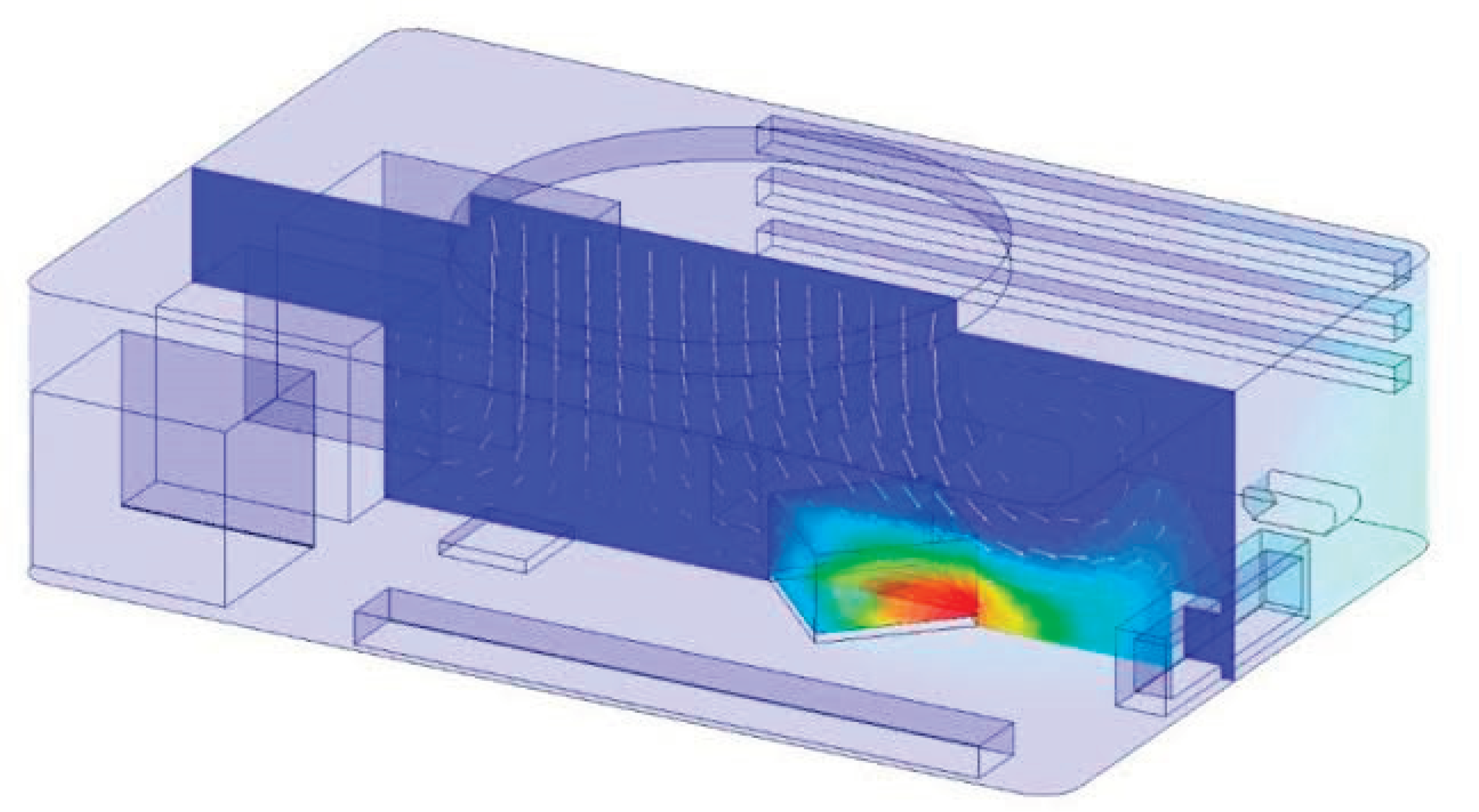
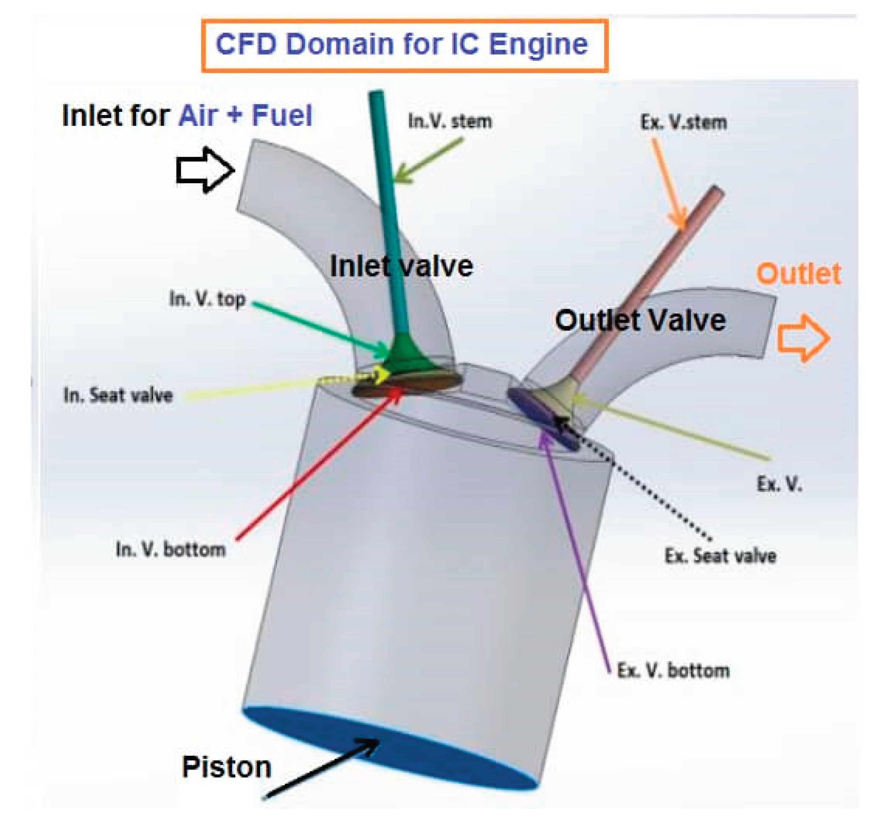
Figure 16: CFD Domain for Internal Combustion Engine This figure showcases the Computational Fluid Dynamics (CFD) domain specifically tailored for internal combustion engines. CFD is a powerful simulation technique that allows us to analyze and understand the fluid flow, heat transfer, and combustion processes within the engine. In this figure, the CFD domain provides an intricate representation of the engine's geometry and the surrounding fluid flow, enabling advanced simulations and analysis.
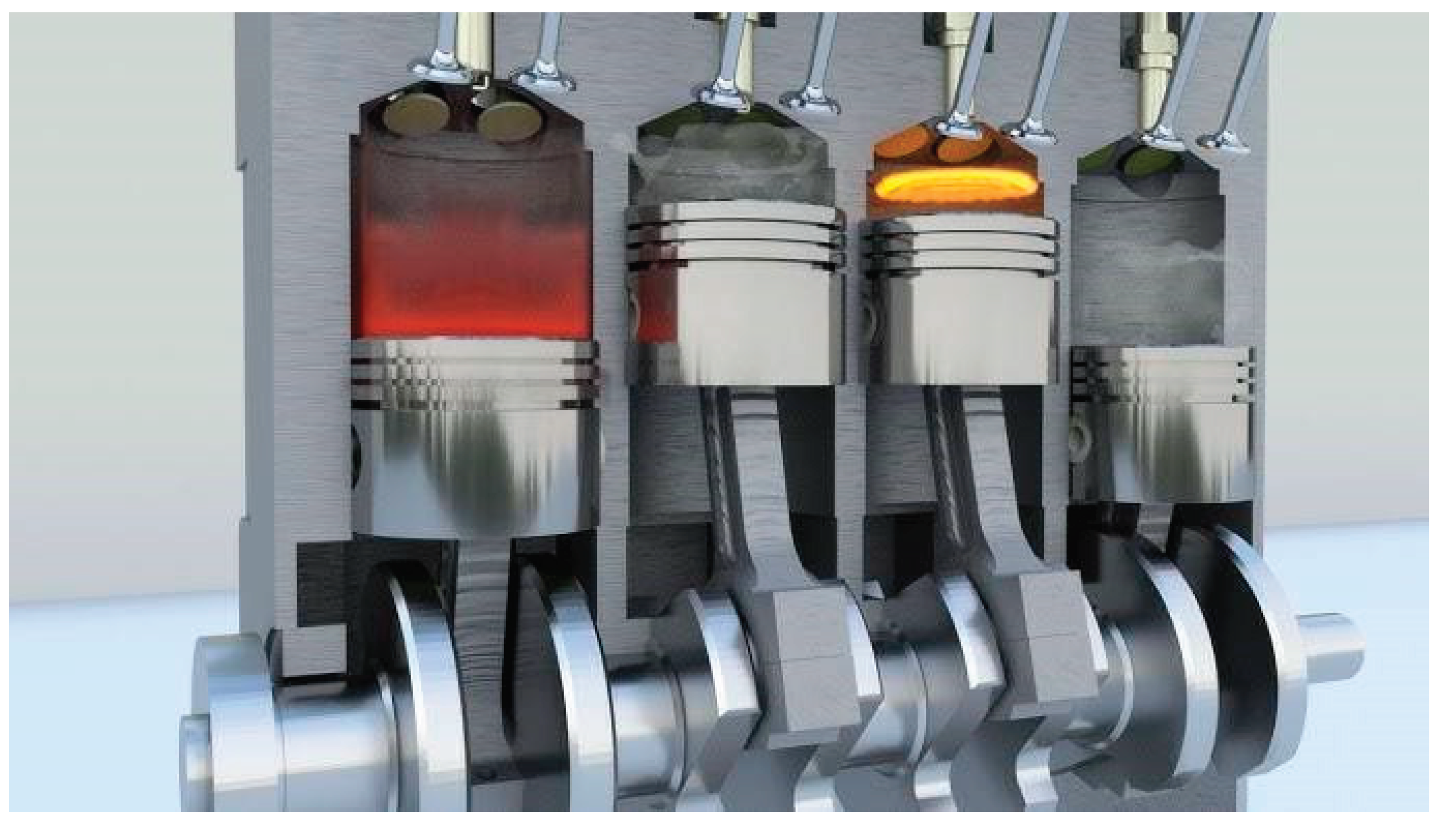
Figure 17: Internal Combustion Engine Simulation
Figure 17 presents a simulation of an internal combustion
Simulation plays a crucial role in understanding and optimizing engine performance. By utilizing sophisticated mathematical models, this figure demonstrates the ability to virtually recreate the engine's operation. It allows researchers and engineers to examine various factors like fuel-air mixing, combustion efficiency, and emissions generation, leading to improvements in design and performance
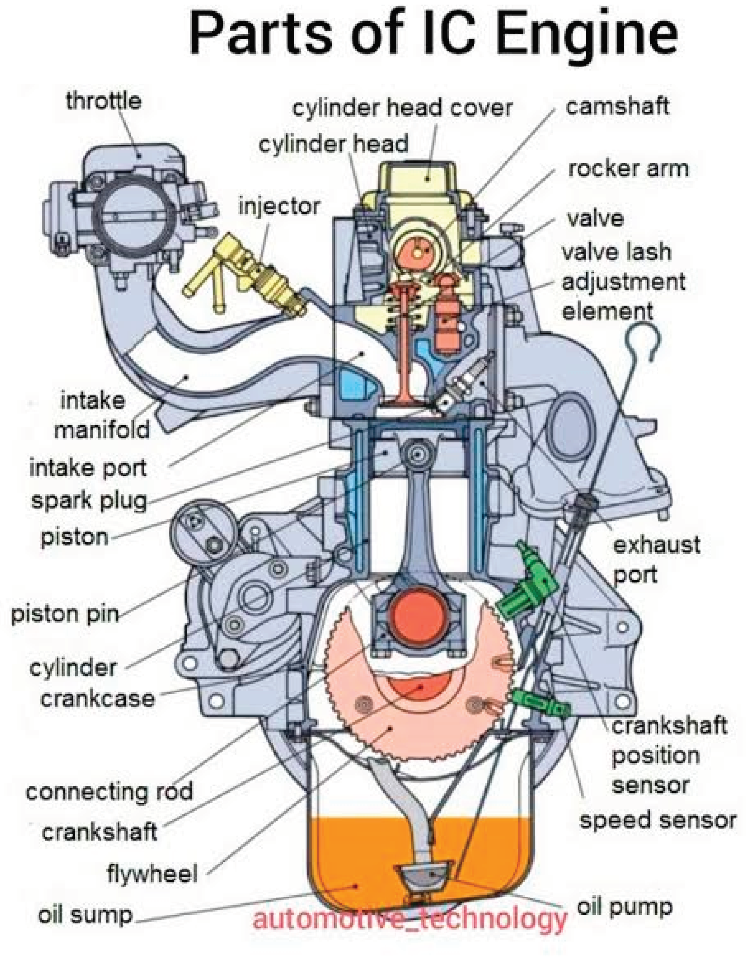
Figure 18: Full Part of Internal Combustion In
Figure 18, we witness a comprehensive representation of a specific part of an internal combustion engine. This figure focuses on providing an in-depth view of a particular component within the engine, allowing for detailed analysis and optimization. By studying individual parts, engineers can identify areas for improvement, enhance durability, and optimize performance by fine-tuning specific feature
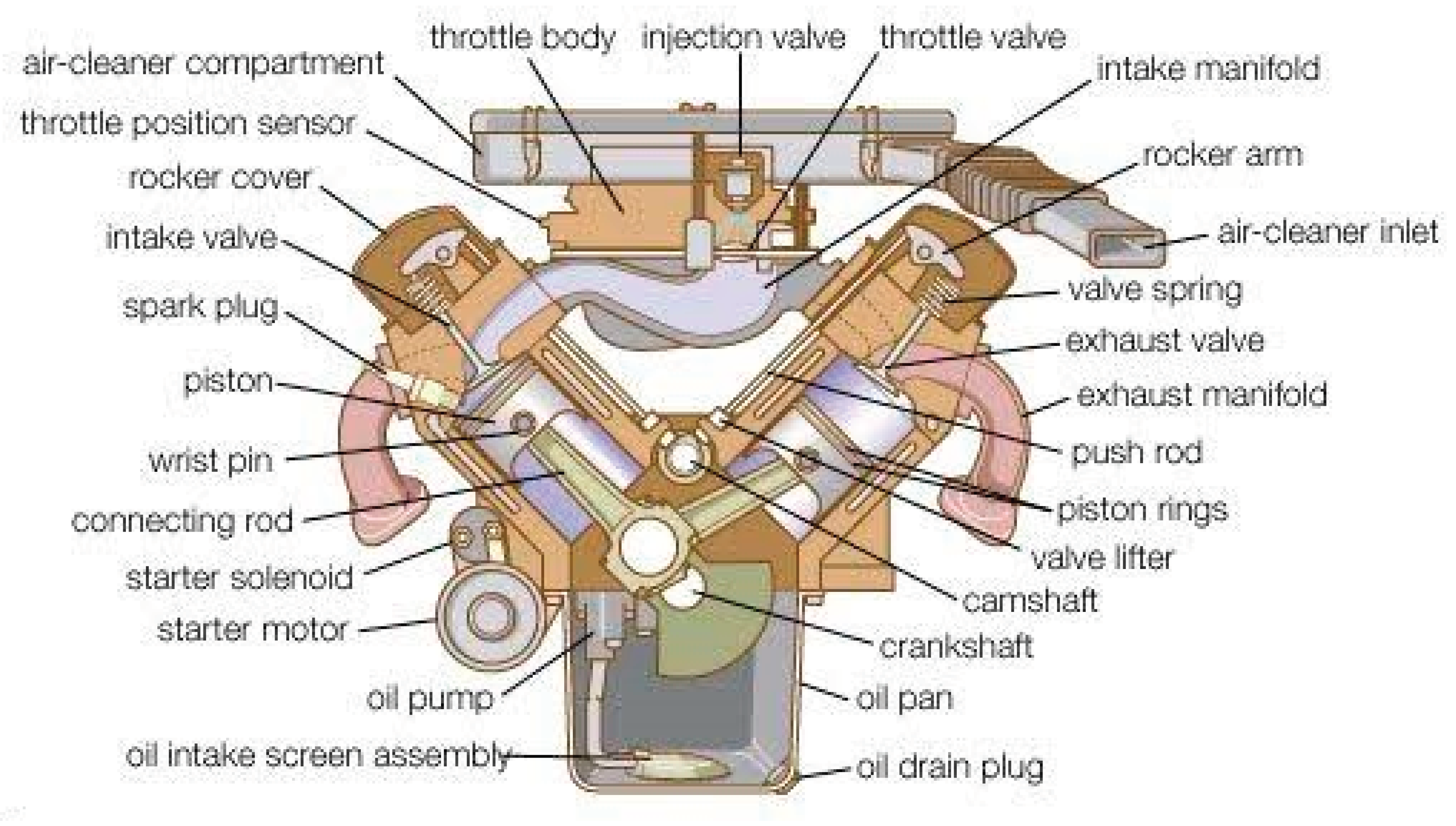
Figure 19: Diesel Combustion Engine
Figure 19 showcases a diesel combustion engine, which operates on the principle of compression ignition. This figure provides a visual depiction of the internal workings of a diesel engine, including the fuel injection system, combustion chamber, and piston arrangement. By studying diesel combustion engines, researchers can develop strategies to enhance fuel efficiency, reduce emissions, and optimize the overall performance of these engines.
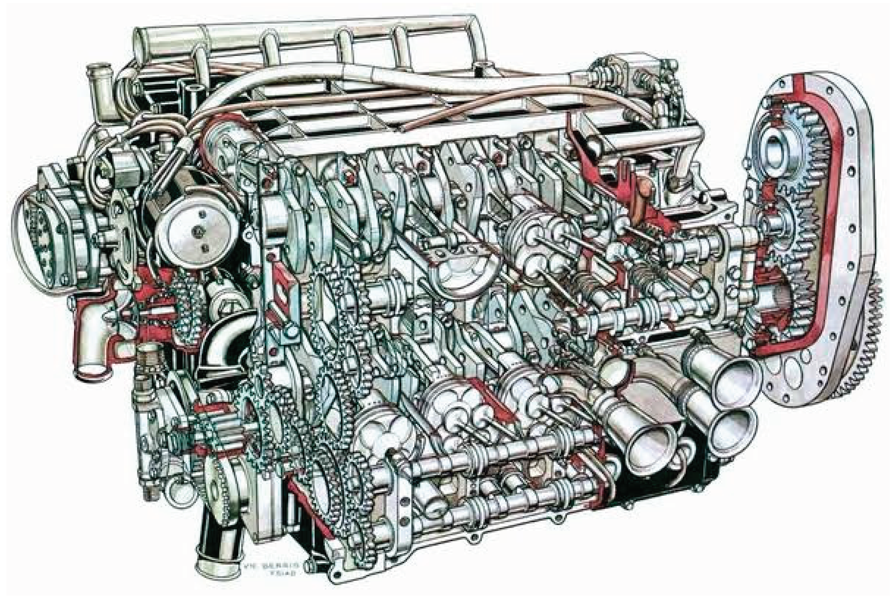
Figure 20: A Full Comprehensive IC Engine
Figure 20 represents a comprehensive view of an internalcombustion engine, encompassing various components, subsystems, and their interactions. This figure provides a holistic understanding of the complex nature of internal combustion engines, enabling
researchers to optimize the engine's overall performance, efficiency, and reliability. It serves as a visual guide to analyze the integrated system and identify opportunities for advancements in areas like combustion control, emissions reduction, and energy conversion efficiency
These figures collectively contribute to the advancement of research in compartment rotor combustion engines by offering detailed insights into the internal workings, simulation techniques, and optimization possibilities. By leveraging these advanced tools and techniques, researchers can revolutionize the power and potential of dynamic mathematical model simulations for internal combustion engines.
Figure 21: Gasoline Engine Operation
Figure 21 provides insights into the operation of a gasoline engine. This figure elucidates the intricate processes involved in the combustion of gasoline fuel, including fuel injection, spark ignition, and power generation. By analyzing the gasoline engine's operational characteristics, researchers can optimize parameters like air-fuel ratio, ignition timing, and valve timing to maximize efficiency, power output, and reduce emissions.
Figure 22: Full Motion of Internal Combustion Engine In
Figure 22, we witness a dynamic representation of the internal combustion engine in full motion. This figure showcases the movement of various engine components, such as pistons, valves, and crankshafts, during the engine's operational cycle. By studying the full motion of an internal combustion engine, researchers gain insights into the complex mechanical interactions and can identify opportunities for improving engine performance, reducing vibrations, and enhancing durability
Figure 23: Modelling Design of IC Engine of Diesel
Figure 23 focuses on the modeling and design aspects of a diesel internal combustion engine. This figure represents the use of advanced simulation tools and techniques to model and optimize the design of a diesel engine. Researchers can analyze parameters like combustion chamber shape, piston design, and fuel injection strategies, aiming to achieve better fuel efficiency, lower emissions, and improved overall performance.
Figure 24: CFD Simulation of Reacting Flows and Combustion in Diesel Engine
Figure 24 showcases the application of Computational Fluid Dynamics (CFD) in simulating reacting flows and combustion within a diesel engine. This figure highlights the use of advanced numerical methods to simulate and analyze the complex combustion process occurring in the engine. By conducting CFD simulations, researchers can gain crucial insights into fuel-air mixing, combustion efficiency, and emission formation, ultimately leading to the development of more efficient and cleaner diesel engine.
These additional figures further expand our understanding of gasoline and diesel internal combustion engines, their operational characteristics, design optimization, and simulation techniques. By leveraging these figures and their associated research, we can unlock new possibilities for revolutionizing power and efficiency in internal combustion engines.
5. Conclusion
In this research, the aim was to enhance the air flow characteristics of a 4-stroke diesel engine by modifying the engine rotor with multiple compartments on the rotor crown. Through the analysis and investigation using Fluent 6.3 CFD code with dynamic mesh, several important findings were drawn. The analysis of air flow characteristics during the suction and compression strokes revealed significant improvements with the modified engine design. The introduction of multiple compartments on the rotor crown resulted in enhanced air flow patterns, leading to improved fuel-air mixing and combustion efficiency. The CFD analysis demonstrated increased tumble ratio and squish velocity in the modified engine compared to the base engine. These improvements indicate better air motion within the combustion chamber, facilitating more efficient combustion and heat transfer processes. Overall, the research highlights the potential of modifying the engine rotor with multiple compartments to optimize air flow characteristics in 4-stroke diesel engines. The findings suggest that this modification has the potential to improve engine performance, fuel efficiency, and reduce emissions. These results contribute to the ongoing efforts in the development of more efficient and environmentally-friendly combustion engines. Further research and experimentation are encouraged to validate and refine the findings, paving the way for future advancements in diesel engine design and power generation.
The investigation and analysis of the modified engine design revealed several significant improvements in air flow characteristics compared to the base engine.
1, the peak tumble ratio of the modified engine was found to be 0.88, which represents a 35% improvement over the base engine's tumble ratio of 0.65. This indicates enhanced air motion within the combustion chamber, leading to better fuel-air mixing and improved combustion efficiency.
2., the peak tumble ratio in the modified engine was observed to shift towards top dead center (TDC) by 10° compared to the base engine. This shift in timing suggests a more optimal fuel-air mixture formation and ignition, potentially resulting in improved engine performance.
3, the squish velocity of the modified engine was increased by 31% compared to the base engine. This higher squish velocity contributes to better air-fuel mixing and a more efficient combustion process. Overall, these findings demonstrate the positive impact of the modified engine design on air flow characteristics, specifically the tumble ratio and squish velocity. These improvements have the potential to enhance engine performance, fuel efficiency, and reduce emissions. The analysis of the modified engine design revealed significant improvements in cylinder pressure, tumble, and squish characteristics compared to the base engine.
4, the maximum cylinder pressure in the modified engine was measured at 55 bar, representing a remarkable 45% improvement over the base engine's pressure of 38 bar. This increase in pressure indicates enhanced combustion efficiency and potential for higher power output.
5, the peak pressure in the modified engine was observed to shift towards top dead center (TDC) by 10° compared to the base engine. This shift in timing suggests improved combustion characteristics, which can lead to better engine performance.
6 the study clearly indicates that the modified rotor design has the capability to generate higher tumble and squish. This is a crucial observation as it enhances the combustibility of the fuel-air mixture during combustion. The higher tumble and squish promote better fuel-air mixing and combustion stability, leading to improved engine efficiency. These findings underscore the potential of the modified engine design to enhance cylinder pressure, tumble, and squish characteristics, ultimately improving the overall combustion process. Further research and experimentation are recommended to validate and optimize these results, paving the way for the development of more efficient and environmentally-friendly engines.
References
- Flow field development in a direct injection diesel engine with different manifolds by Benny Paul1*, V. Ganesan2. International Journal of Engineering, Science and Technology 2010, 2, 80–91. [Google Scholar]
- Computational Analysis of Egr Mixing Inside the Intake System & Experimental Investigation on Diesel Engine for Lcv by S Karthikeyan R. Hariganesh, M. sathyanadan S. Krishnan, p. Vadivel, D vamsidhar. International Journal of Engineering Science and Technology (IJEST) 2011, 3, 2350–2357. [Google Scholar]
- Turbulence and Heat Transfer Analysis of Intake and Compression Stroke in Automotive 4-stroke Direct Injection Engine. Algerian Journal of Applied Fluid Mechanics 2007, 1, 37–50.
- Automatic Mesh Motion, Topological Changes and Innovative Mesh Setup for I.C.E. CFD Simulations by T. Lucchini, G. D ‘Errico.
- In An Engine Valve Lift Visualization and Simulation Performance Using Cfd by Semin, Rosli Abu Bakar, Abdul Rahim Ismail and Ismail Ali, Conference on Applications and Design in Mechanical Engineering, 25-26 October 2007, Kangar, Perlis, Malaysia.
- Diesel Engine Simulation with Tabulation of Dynamic Adaptive Chemistry and Adaptive Local Mesh Refinement by G. D ‘Errico, D. Ettorre, T. Lucchini, F. Contino.
- Heywood, JB. Fluid motion within the cylinder of internal combustion engines. The 1986 Freeman Scholar Lecture. J Fluids Eng 1986, 109, (1987). [Google Scholar] [CrossRef]
- F. Payri, J. Benajes, X. Margot, A. Gil ―CFD Modeling of the in-Cylinder Flow in Direct-Injection Diesel Engines. Computers & Fluids 2004, 33, 995–1021. [Google Scholar]
- A. R. Noorpoor, ―Flow Simulation in Engine Cylinder with Spring Mesh‖. American Journal of Applied Sciences 2008, 5, 1336–1343. [Google Scholar] [CrossRef]
|
Disclaimer/Publisher’s Note: The statements, opinions and data contained in all publications are solely those of the individual author(s) and contributor(s) and not of MDPI and/or the editor(s). MDPI and/or the editor(s) disclaim responsibility for any injury to people or property resulting from any ideas, methods, instructions or products referred to in the content. |
© 2024 by the authors. Licensee MDPI, Basel, Switzerland. This article is an open access article distributed under the terms and conditions of the Creative Commons Attribution (CC BY) license (http://creativecommons.org/licenses/by/4.0/).


