Preprint
Article

Designing an Efficient Hybrid Energy Harvesting System Compatible with Head/Wrist-Worn Medical Wearable Devices

Altmetrics

Downloads

216

Views

132

Comments

0

Submitted:

25 March 2024

Posted:

26 March 2024

You are already at the latest version

Alerts
Abstract
Keywords: Energy harvesting, Hybrid, Medical Wearable Sensor Nodes, Health Monitoring, Power Management
Keywords: 
Subject: Engineering  -   Bioengineering

1. Introduction

With the global spread of the coronavirus (COVID-19) disease, the importance of remote monitoring of human health has multiplied. In this context, wearable devices have gained additional attention in healthcare [1,2]. These devices can seamlessly integrate into individuals' daily lives and, through continuous monitoring of vital signs, serve as an effective solution for early disease detection [3]. This early diagnosis can result in preventive measures and prompt therapeutic solutions, preventing the progression of the disease and reducing some of the costs associated with emergency and hospital care [4,5]. Additionally, the use of wearable devices in remote areas can enhance the efficiency of healthcare services, quality of life (QoL), and overall well-being. This fosters a sense of responsibility for one's health and, consequently, promotes a shift towards a healthier lifestyle [6]. Such a trend is in-line with the focus shifts towards preventive strategies, predictive assessments, precision prevention, and proactive health management rather than treatment after diagnosis. Therefore, with surveillance, assessment, and continuous data provision, these devices assist in early detection of users' health issues, transforming into a promising approach for preventive healthcare [7].
Wearable technologies encompass electronic devices like smartwatches, wristbands, and augmented reality glasses, often include various physiological/non-physiological sensors, data processing unit, and communication components. They are capable of collecting a diverse range of data, including heart rate (HR), blood pressure (BP), respiratory rate, blood oxygen levels, body movement and physical activity, and more, providing valuable insights into an individual's well-being and overall health [8]. Applying wearable technology for health monitoring goes beyond vital signs and physiological measurements, significantly enhancing QoL of users [9]. In the realm of wearable technology, the proliferation of unobtrusive, non-intrusive, and non-invasive devices signifies a key advancement in user-centered design [10,11,12]. Unobtrusiveness ensures that these wearables seamlessly integrate into daily life with a compact and lightweight form factor that minimize interference and have minimal impact on user’ daily routine [10]. Non-intrusiveness demonstrates the capabilities of these devices to operate in the background, collect data, and provide services without drawing the user's attention and violating privacy. Meanwhile, non-invasiveness underscores a commitment to user comfort, as these wearables extract information from the external surface of the body without invasive methods. These features are particularly important in continuous health monitoring, where unobtrusiveness, non-intrusiveness, and non-invasiveness are gaining attention and playing the critical roles in increasing the penetration rate in practical applicability [13,14]. Although the user acceptance, adaptation, and integration of technology into daily activities are influenced through these characteristics, however, there is a hindrance in the practical use of wearable devices, stemming from issues related to battery recharging and battery life among other aspects such as accuracy, reliability, and clinical use [6]. Consequently, with improved battery performance and extended measurement times, users will no longer worry about the frequent recharging of their wearable devices or experiencing interruptions in their health monitoring by missing data slices [15]. These factors will further improve the user-friendliness and unobtrusiveness of the wearable systems and encourage individuals to integrate them into their daily routines for continuous health tracking [16].
With the reduction in size and power consumption of electronic circuits, integrating data processing units, and communication components, the real-time monitoring and analysis were enhanced which allow healthcare professionals to remotely monitor patients' progress and make informed decisions regarding their medical care [17]. These devices serve as a valuable tool in providing real-time health tracking data, especially for individuals dealing with chronic illnesses such as asthma, chronic obstructive pulmonary disease (COPD), diabetes, mobility impairments, and cardiovascular diseases [18].
The photoplethysmogram (PPG) sensor has the potential for continuous vital signs monitoring, paving the way for early detection of anomalies or fluctuations in a patient's health that has been integrated into wearable medical devices. It holds exceptional promise for patients with cardiovascular issues, COPD, respiratory diseases, and those with cardiorespiratory disorders [19]. Furthermore, the unobtrusiveness and noninvasiveness deployment of the PPG sensor (e.g. in form of wrist-worn) transforms it into an accessible resource for continuous monitoring [20].
Another significant sensor employed in wearable devices is the accelerometer. It is highly valuable in identifying movement-related disorders, such as Parkinson's disease, and is particularly useful for individuals dealing with Alzheimer's disease. The continuous data collection aspect aids in identifying long-term changes in their mobility and physical activity [21].
Despite the mentioned advantages of using wearable devices and some of the most popular and contributing sensors with the applications, yet the electronic devices rely on batteries to power themselves. However, a heavy reliance on batteries comes with drawbacks, especially when considering environmental concerns, safety implications, and overall reliability. Moreover, the considerable size and weight of these batteries inevitably reduces the inherent flexibility of wearable devices. Most Internet of Things (IoT) devices and wireless sensor networks are powered by rechargeable secondary batteries [22]. Therefore, a primary concern in these scenarios revolves around the necessity of a continuous power source. This dilemma has led to the emergence of innovative solutions, particularly in the field of energy harvesting approaches and power management systems. Energy harvesting techniques involve capturing and utilizing environmental energy sources such as solar energy [23], thermal energy [24], vibrations [25], kinetic energy [26], and radio frequency (RF) [27] energy to supply power to wearable devices. Additionally, efficient power management systems optimize the use of available energy, ensure longer battery life, reduce the need for frequent recharging, and store the harvested energy from the environment or the individual's body in an energy storage unit, ultimately used to power the consumer load. The block diagram of the energy harvesting system is presented in Figure 1 [28].
The power density of various energy sources is provided in Table 1. Accordingly, solar energy in outdoor environments has the highest power density among other energy sources. However, in many cases, it may not fully meet the needs due to the instability of these sources and their temporal-spatial unavailability. To address this issue, the use of hybrid energy harvesting systems was introduced as an effective solution, capable of harvesting energy from multiple sources [29]. Hybrid energy harvesting systems have the advantage of providing a more reliable and stable power source by harnessing energy from various sources. By integrating various energy harvesters such as PV panels, thermoelectric generators (TEG), kinetic harvesters, RF harvesters, and more, these systems can ensure a continuous flow of energy even when a single source is unavailable or not producing sufficient power. This not only increases the overall power density but also enhances the system's stability and efficiency [29].
Several single-source and hybrid energy harvesting systems for healthcare monitoring applications have been introduced. Yaoguang et al [30] proposed a wearable TEG, harvesting the heat from the human body. The TEG device's structural architecture is made up of 12 TEG modules that are electrically linked in series and connected in parallel via copper strips. When walking, this wrist-worn TEG device captures body heat, produces more power than when stationary. The requirements analysis and performance evaluation of the wearable sensors in medical applications was presented in [26], which addresses the fundamental issue of piezoelectric kinetic energy harvesting devices. In [31], a kinetic energy harvesting device is used instead of an accelerometer to assess calorie consumption as kinetic energy is generated when the user expends calories through bodily movements. A wearable medical sensor system for long-term health monitoring is described in [28]. This device measures temperature, HR, blood oxygen saturation (SpO2), and human body acceleration in real-time. In [32], a rotating piezoelectric energy harvesting device was tested and developed, capable of receiving a maximum power of 7μW when worn on the arm during activities. Additionally, in [33], a flexible piezoelectric generator for harvesting energy from the dynamic movement of the ear canal has been developed. In [34], a scalable triboelectric energy harvesting system for electronic textiles to extract energy from daily human movement was proposed. The suggested energy harvester was scalable, stretchable, and wearable. The output power of this system is enhanced by the capacitor capacity, as well as the mechanical input frequency, providing guidance for practical applications. One drawback of this system is the ability to power wearable electronic devices only during human movement, and there are significant power losses due to the high rectifier losses. In [35], a wearable sensor system in the form of glasses has been proposed. This sensor system employs algorithms for detecting and identifying chewing cycles using a piezoelectric pressure sensor placed on a temporalis muscle. This study suggests the possibility of further compressing electronic devices to improve user comfort. Additionally, further studies are needed to explore new methods of connecting sensors, such as embedding sensors in glasses handles. In [36], a novel hybrid energy harvesting technology was presented to power on wearable electronic devices. A flexible and wearable energy harvesting device that combines solar and RF energy was developed in this study. This work represents the first flexible and wearable hybrid system of solar and RF energy harvesting, experimentally placed on the human body. Furthermore, aiming to increase the reading range of active RFID tags and provide a compact multifunctional structure, a hybrid solar and RF energy harvesting system was introduced in [37]. This system includes components such as monocrystalline solar panels, a charging circuit, a rectifier, the EM4325 chip as the receiver antenna, and an RFID tag. Authors in [38] proposed a flexible TEG module that is appropriate for biomedical and wearable devices due to its high-power density on a small scale and flexibility due to its flexible form factor. In [39], various methods were examined to utilize the heat and mechanical energy of the human body for wearable energy harvesting. The focus is on harvesters such as TEG, PV, piezoelectric, electromagnetic, and electrostatic harvesters. This work includes hybrid energy harvesters that hybrid the conversion of two or more energy sources to achieve maximum power density.
Typically, in the structures of hybrid energy harvesting systems, Schottky diodes, such as the 1N5817 diode, are used for combining input sources, which have high power losses and voltage. This technique is called "OR-ing," and it is applied either before or after the voltage conversion stage. While using this technique before the voltage conversion stage has the advantage of using a single voltage converter for both sources, it forms a parallel structure of energy sources and limits the power sources to have the same internal impedance. This results in the load being supplied by one of the energy sources that has a higher voltage compared to the other source until another diode has a higher voltage. Therefore, at any given time, only one energy source can be used [28,40,41].
Accordingly, to overcome this drawback, in this work, we present a hybrid energy harvesting system designed to empower and comply with a wide range of wearable medical sensors such as those worn on head and wrist but not limited to them. The primary objective of this system is to design and implement a compact and efficient double-source harvesting energy system that simultaneously harvests from solar and body heat sources, leading to an extended battery and system lifespan. This energy harvester relies on compact PV panel and TEG modules. The collected energy from these origins is stored in a 3.7 V, 300 mAh lithium battery, facilitating system charging. Additionally, two ultra-low-power DC/DC boost converters are employed to efficiently obtain and manage the generated powers from PV and TEG sources. The DC/DC boost converters ensure that the harvested energy is effectively converted to voltage and current levels required for the system load, providing optimal use of available energy and increasing the overall battery life. Moreover, the utilization of diminutive PV panel and TEG modules contributes to a streamlined and lightweight design, rendering it well-suited for a variety of wearable applications.
Our contributions in this work are as follows:
  • Designing a double-source hybrid PV/TEG energy harvesting system to achieve MPPT for either input sources, both during battery charging and loading.
  • Implementing the harvesting system with two DC/DC boost converters in which both are active and employed simultaneously. The outputs of these converters are paralleled at their two similar circuit nodes: the battery and the load nodes. Consequently, each power source operates with MPPT, as well as they can charge/supply a common battery/load simultaneously or individually.
  • Implementing a low-cost, compact form factor, and universal harvesting system compatible with various range of wearable medical devices in different mode of wearability such as wrist/head worn.
  • Testing and validating the system in different environmental conditions with the most impact and practical medical sensors such as IMU and PPG with the capability of turning into a self-powered system.
The rest of this work is organized as follows: in Section 2 the materials, methods, and the study design is described. We present the experimental results in Section 3. This is then followed by the discussion in Section 4 and we conclude in Section 5.

2. Materials and Methods

We provide a requirement analysis in terms of the most popular and frequent used sensors in health assessment, an investigation into the energy consumption of these sensors, the components of the circuit, the proposed circuit, and the evaluation methodology. Considering the continuous and constant need for the physiological sensors in measuring vital signs and health monitoring, the power supply of these sensors, which is typically provided by batteries, becomes a significant issue, posing constraints on these systems.
The design and implementation of the hardware harvesting system and medical sensors and components are PV panel, TEG module, a lithium battery, and two BQ25504 ultra-low-power DC/DC boost converters, MAX30102, and MPU6050.
To meet the desired power requirements, we considered two ultra-low-power DC/DC boost converters for the PV and TEG sources, with identical configurations for battery settings. The ultra-low-power DC/DC boost converter controls the output voltage of the PV panel and TEG module. The low-power IC B25504 is the basis for this converter and the proposed structure, accepting a maximum absolute input and output voltage range from -0.3 V to 5.5 V. This device can be used on a person's face/head and wrist as wearable glasses or wristbands.

2.1. Vital Data and Medical Sensors

PPG is a non-invasive technique used to detect vital signs such as HR, SPO2, and BP. The carotid artery in the neck, physical heartbeats in the chest cavity, or the radial artery on the wrist can all be used for manual HR counting. Wearable finger/wrist/earlobe/forehead/temporal region-type PPG devices have been increasingly developed for the convenience of individuals under supervision [42]. Two important features of wearable PPG devices are high accuracy and long operating time due to lower power consumption if optimized. The MAX30102 sensor provides a convenient and efficient solution for real-time monitoring of vital signs via red/infrared/combination. It offers reliable HR and SPO2 measurements, making it suitable for various applications of medical monitoring such as heart diseases, high BP, coronary artery disease and heart failure. Furthermore, its compact form factor, low power consumption initialization, wide range of voltage support, and supporting inter-integrated circuit (I2C) protocol compatible with wide range of embedded systems allows easy integration into various wearable devices, ensuring connectivity and data transmission [42,43,44].
This sensor consumes 6 mA in measurement mode and 2.7 mA in its sleep mode. Due to its low energy consumption, the MAX30102 can be used in products such as smartphones, smart bracelets, and smartwatches with battery efficiency. The MAX30102 chip requires two separate supply voltages: 1.8 V for the IC and 3.3 V for the red and infrared LEDs. Therefore, the module includes 3.3 V and 1.8 V regulators. The sensor has compact dimensions of 5.6 mm × 3.3 mm × 1.55 mm.
Another common example of sensors used in wearable technologies for health monitoring is accelerometers. These sensors can measure physical activity by detecting changes in acceleration. The characteristics of physical activity are a good indicator of an individual's level of mobility, the presence of hidden chronic diseases, and the aging process, as reduced physical activity is a significant factor in many diseases and associated functional disorders. By using the gyroscope and accelerometer present in MPU6050, rotation along all three axes, static acceleration due to gravity, and dynamic acceleration due to motion can be measured. This sensor combines a 3-axis accelerometer and a 3-axis gyroscope to provide accurate motion tracking data. This capability enables precise motion measurement in directions with 16-bit resolution. [45,46,47]. The current consumption is 4.8 mA when active. Thus, due to its low energy consumption, it can be utilized in wearable devices.

2.2. Proposed Hybrid Energy Harvesting System, and Hardware Specification

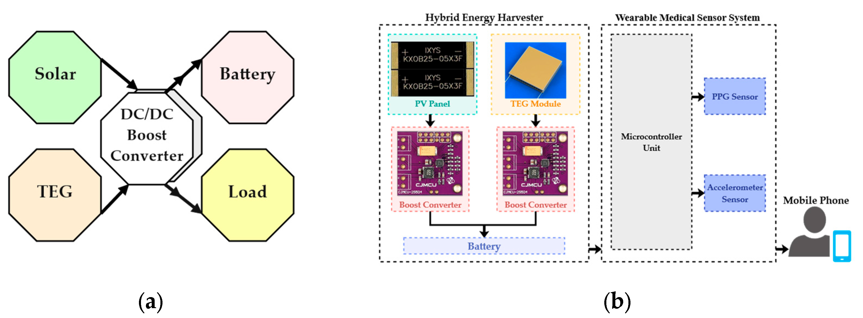
The proposed block diagram and the sensor system development of the hybrid energy harvesting system are shown in Figure 2. (a) and (b), respectively. This structure includes a PV panel for solar energy harvesting, a TEG module for body thermal energy capture and two DC/DC boost converters. These converters are independent at their input terminals to connect and boost one of the input DC voltages of the PV panel and TEG module. In the later stage, they become parallel at their two output terminals for connecting a battery storage and a microcontroller unit (NodeMCU Board) as a load. We utilized to operate, acquire, and process the sensors MAX30102 and the MPU6050 and data.

2.2.1. Solar Panel

We chose solar cell, model KXOB25-05X3F (× 10) from IXYS, each with dimensions of 23 mm × 8 mm x 1.8 mm and a maximum power of 30.7 mW under standard conditions: 25℃ temperature and 1000 W/m2 irradiance. This PV panel consists of a series and parallel connection of these ten cells with an area of 1840 mm2, every two cells are connected in series, and ultimately, five strings are connected in parallel. This model has a 25% power conversion efficiency. The KXOB25-05X3F solar cell is designed to work effectively even in low light conditions and is suitable for various applications. Its small dimensions and its light weight allow easy integration into wearable devices or in applications where limited space is available. The electrical characteristics of this cell are given in Table 2. All values measured at standard condition: 1 sun (= 100m W/cm2), Air Mass 1.5, 25 °C

2.2.2. TEG Module

We used IMC06-126-03 TEG module with dimension of 16mm × 16mm and thickness of 1.4mm, integrated in the hybrid energy harvesting system. Four TEG modules chained in series formed the total area of 1024 mm2. The polarity of the TEG depends on the direction of the cold and hot sides. These TEGs are used to harvest energy from the body heat. The performance parameters are provided in Table 3 for the TEG cold side in dry air at 27 °C.

2.2.3. DC/DC Converter and Power Management Unit

The DC voltage produced by PV/TEG energy harvesters is typically low. DC/DC power converters, such as boost converters, are used in the power management circuit to increase the voltage to the required level.
To convert environmental energy into electrical energy, integrated energy harvesting ICs can be used. Choosing an appropriate energy harvesting IC is influenced by various factors, which the most important one is the type of energy source, i.e. solar energy, thermoelectric energy, RF energy, piezoelectric, electromagnetic, etc. Other factors to consider include input/output voltage ranges, cold-start voltage, minimum input power to cold-start, and quiescent current consumption.
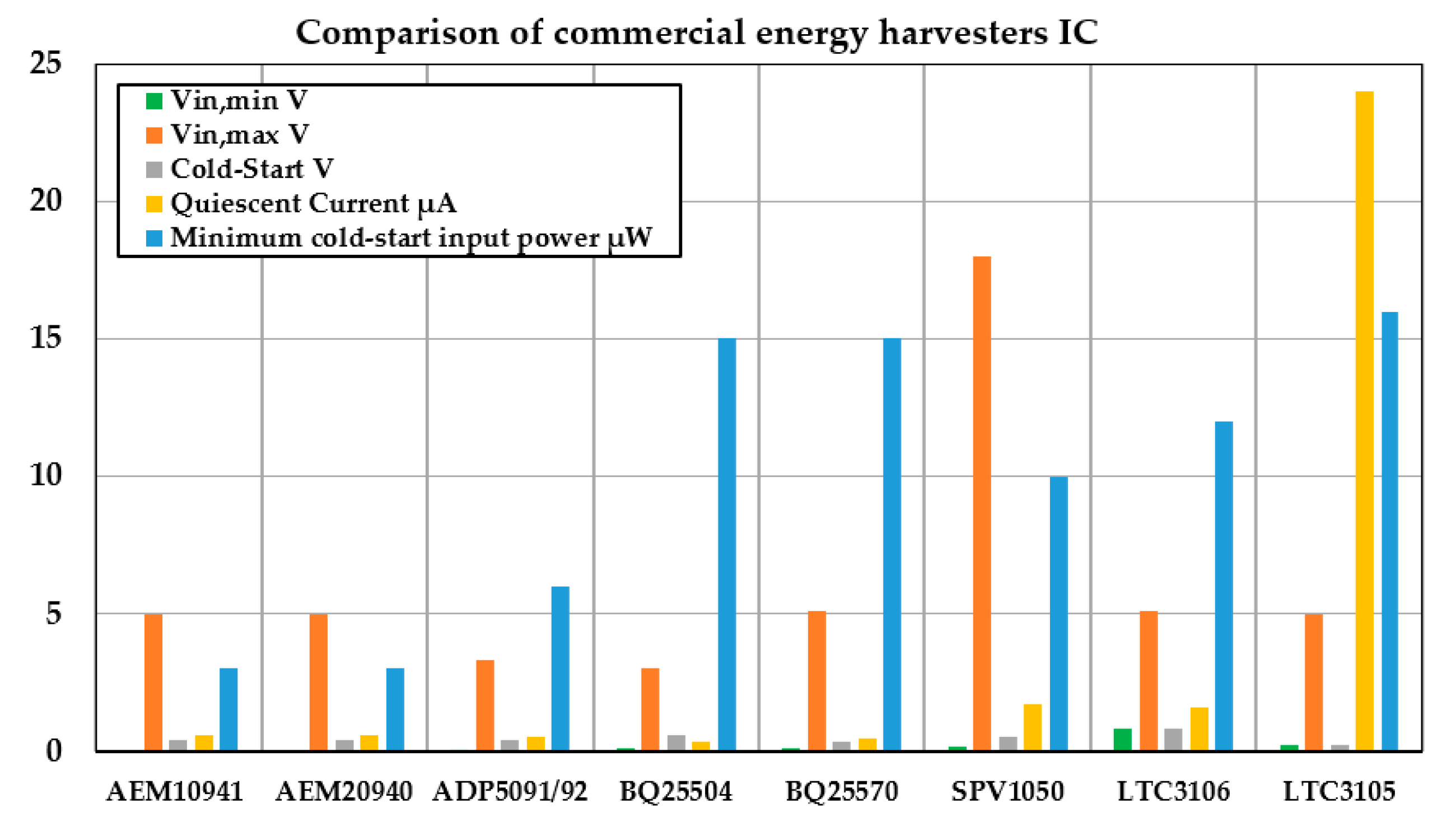
Based on the impacting parameters, we identified, summarized, and compared the influencing characteristics of several ICs from different companies such as Texas Instruments (TI), STMicroelectronics, Analog Devices, and E-peas on their relevance to PV and TEG input sources (see Figure 3) [48,49,50,51,52,53,54,55].
The integrated energy management circuit AEM10941 (E-peas, Ottignies-Louvain-la-Neuve, Belgium), utilizes DC energy from solar panels with a maximum of seven cells. It provides the system with two separate regulated voltages while simultaneously storing energy in a rechargeable element [48]. Additionally, for simultaneous energy storage in a rechargeable element and providing a system with two separate regulated voltages, the integrated energy management AEM20940 (E-peas, Ottignies-Louvain-la-Neuve, Belgium) extracts DC power from a TEG [49]. The BQ25504 (Texas Instruments, Dallas, Texas, United States), is an ultra-low-power boost converter and battery management system designed for extracting power from DC sources such as PV panels or TEGs. Low-input sources, like a 130mV input voltage, can be used to generate energy with BQ25504, requiring only a few microwatts (μW) for cold-start [51]. Another crucial factor in choosing an IC is the quiescent current consumption of the IC. According to Figure 2, both BQ25504 and BQ25570 (Texas Instruments, Dallas, Texas, United States) have very low quiescent current consumption, whereas LTC3105 has a significantly higher quiescent current. Therefore, we concluded that AEM10941, AEM20940, BQ25504, and BQ25570 can be suitable options for circuits related to PV/TEG energy harvesting of the wearables in medical applications, and according to low prices and easy access, in this work, we chose BQ25504.

2.2.4. Energy Storage Unit

The harvested energy is stored in a rechargeable lithium battery with dimensions of 40 mm × 11 mm × 4 mm, capacity of 300 mAh, and a nominal voltage of 3.7 V, which reaches 4.2 V when fully charged. Energy can be stored in supercapacitors, or conventional capacitors, rechargeable lithium-ion batteries, and thin-film batteries.

2.3. Proposed Multi-Port Energy Harvesting Circuit

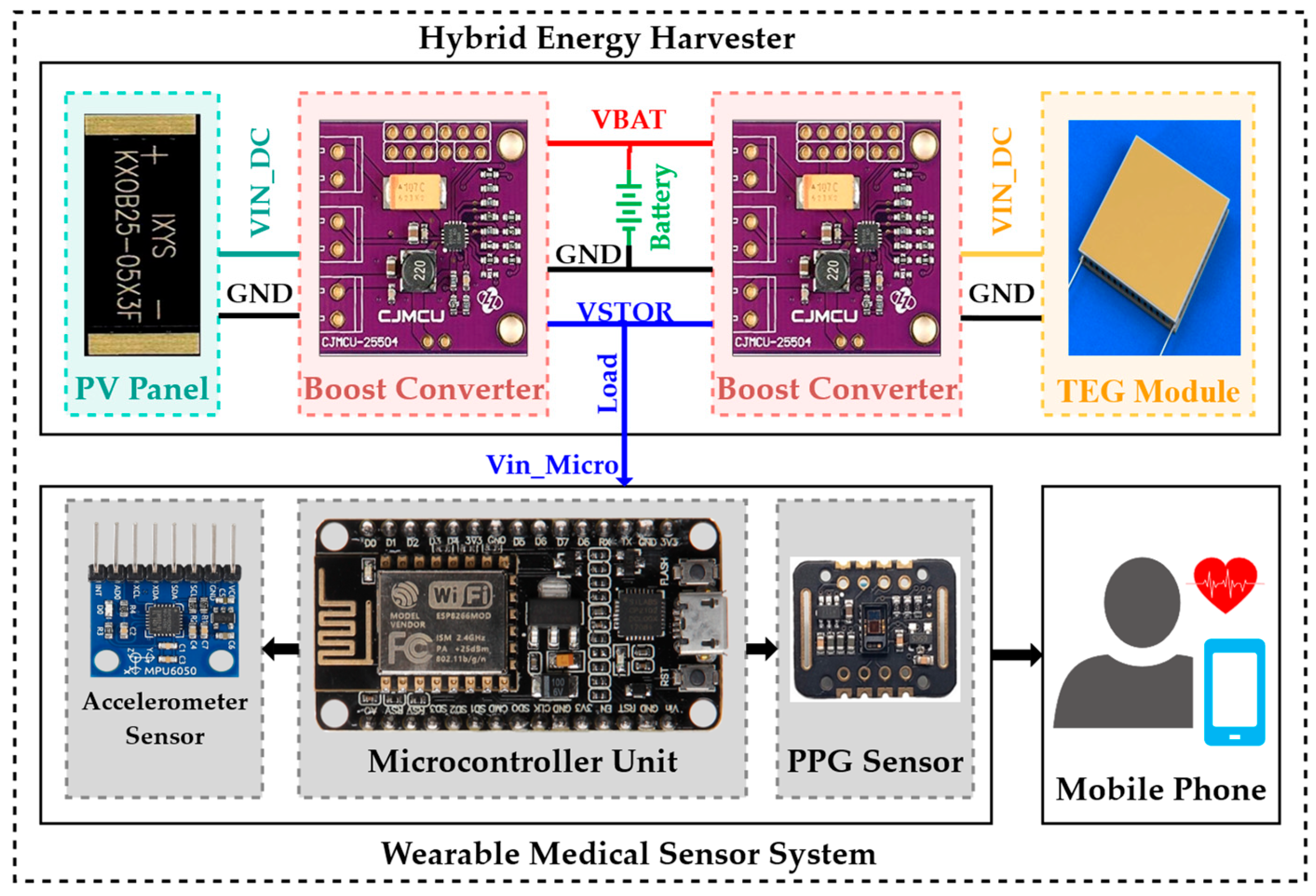
The details of the proposed multi-port energy harvesting power circuit are shown in Figure 4.
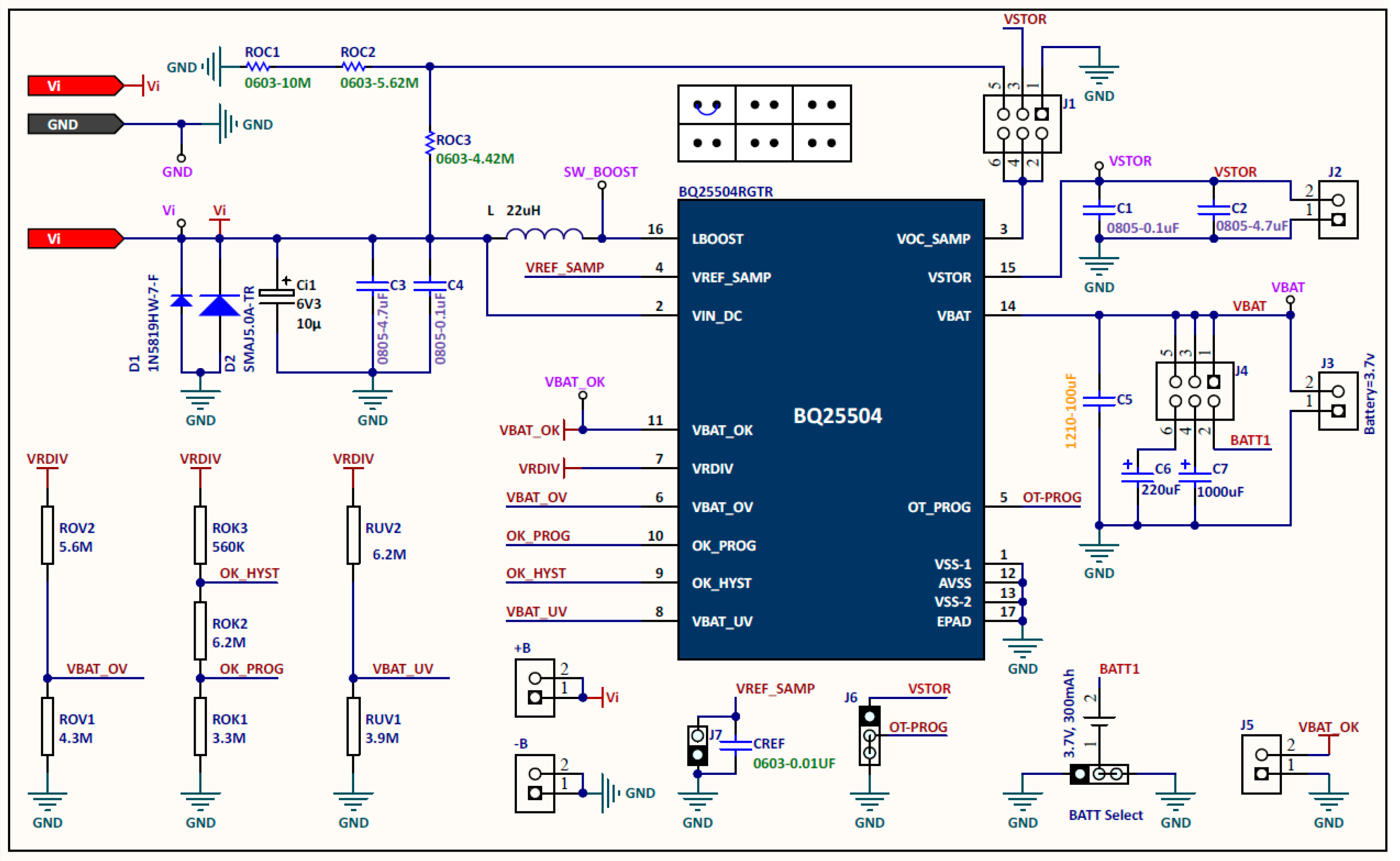
In this structure, both VBAT and VSTOR pins of both converters are connected to each other (output parallel). As a result, a single battery terminal and a single load terminal are achieved by these common pins to integrate the system input battery and output load. The battery overvoltage (OV) and undervoltage (UV) configurations of both boost converters should be designed as the same (see Figure 5). Therefore, each power source operates with MPPT, as well as they can charge/supply a common battery/load simultaneously or individually.

2.3.1. MPPT, Overvoltage, and Undervoltage Protection

MPPT is implemented to maximize the power extracted from the energy harvesting source. The boost converter indirectly adjusts the input impedance of the main boost charger by setting the input voltage of the charger, as sensed by the VIN_DC pin, to the reference voltage stored in the VREF_SAMP pin. The MPPT circuit obtains a new reference voltage every 16 seconds by deactivating the charger for 256 ms and sampling a fraction of the open-circuit input voltage (VOC) of the harvester circuit. For PV harvesters, the MPPT is usually 70 to 80 percent of VOC, and for TEG harvesters, MPPT is typically 50 percent [56]. The precise MPPT ratio can be optimized for the input source requirements by connecting external resistors, ROC1 and ROC2, between VIN_DC and GND with the midpoint at VOC_SAMP, as calculated according to equation (1) [51].
V R E F S A M P = V I N _ D C ( O p e n   C i r c u t ) ( R o c 1 R o c 1 + R o c 2 )
To prevent deep discharge and damage to rechargeable batteries and avoid complete discharge from a capacitor storage element, the voltage threshold (VBAT_UV) is set by external resistors. The voltage threshold VBAT_UV is obtained when the battery voltage is decreasing, as calculated by equation (2):
V B A T _ U V = V B I A S ( 1 + R U V 2 R U V 1 )
Additionally, to prevent rechargeable batteries from being exposed to excessive charging voltages and to avoid overcharging from a capacitor storage element, the threshold level of overvoltage (VBAT_OV) is adjusted using external resistors, as well. This voltage is set by the charger pin VSTOR/VBAT when there is sufficient input power. The VBAT_OV threshold is obtained when the battery voltage is increasing, as calculated by equation (3):
V B A T _ O V = 3 2 V B I A S ( 1 + R O V 2 R O V 1 )

3. Experimental Results

The proposed sensor node, which includes two MAX30102 sensors and an MPU6050, has two operating modes: active mode, in which the MAX30102 sensor is activated for 10 S at a sampling rate of 200 Hz, to record HR data, and then it goes to sleep for 180 S. The MPU6050 sensor module also works continuously with a sampling rate of 50 Hz. We tested and measured the battery lifetime of the sensor node under the condition that the energy harvesting system disconnected. We assumed the total operation time of the node in this case is (T). Therefore, in the active mode, the current consumption of the node is measured: ION = 36 mA for a period of TON = 10 S. Besides, in the sleep mode, we recorded the current consumption of ISleep = 32 mA during TSleep = 180 S. Thus, the average current consumption is Iave = 32.21 mA.
With the node`s operating voltage of 3.3 V, the power and energy are 106.29 mW and 382.6 Joules, respectively. As a result, with the battery capacity of 300 mAh, the total battery lifetime (TBAT) is calculated as 300 mAh/32.21 mA = 9.31 hrs.
To calculate the energy produced by PV panel (EPV), we considered three environmental conditions in which a subject/user wore the sensor node and work comfortably.
  • Sunny day facing the sun,
  • Sunny day back to the sun,
  • Shady or cloudy conditions.
We performed the experiments under these conditions for 10, 60, and 120 minutes.
Under 120 minutes test conditions, the average power of PV panel in direct sunlight, back to the sun, and shaded conditions are 235.5, 140 and 10.25 mW, respectively (see Table 3). Therefore, EPV is calculated using equation (4), which equals 4472.88 joules.
E P V = P P V × t E P V = 2.94 V × 80.1 m A × 4 h + 2.8 V × 50 m A × 2 h + 2.18 V × 4.7 m A × 2 h × 3600 s = 4472.88 J o u l e s
The battery has a capacity of 300 mAh, and the maximum voltage is 4.2 V. So, using equation (5) the battery has stored energy of 1260 joules, where CBAT is the battery capacity, and VBAT is the battery voltage.
E B A T = C B A T × V B A T   E B A T = 300 m A h × 4.2 V = 1260 m W h
The estimated charging time (TCH) of battery by PV energy harvester is measured as:
T C H = E B A T / E P V T C H = 1260 / 4472.88 = 0.28   d a y = 6.72   h r s
Table 3 shows the details of the PV panel test conditions.
Table 3. PV panel testing conditions on a sunny day and measured energy.
Test conditions Sunny day: facing the sun Sunny day: back to the sun
10 min 1 hour 2 hours 10 min 1 hour 2 hours
VPV (V) 2.92 2.91 2.94 2.8 2.7 2.8
IPV (mA) 71.2 63.4 80.1 51.7 48.5 50
PPV (mW) 207.9 184.5 235.5 144.76 131 140
VBATT (V) 3.75 3.96 3.96 3.83 3.81 4.04
Iavrage (mA)1 32.21 33.21 33.21 33.26 34.15 32.21
1[(ISTOR-1[(ISTOR-ON × Tactive-Sensor) + (ISTOR-OFF × Tsleep-Sensor)] /T.
In the same manner, the output energy of the TEG module is measured as follows:
E T E G = P T E G × t T E G
In a scenario where the output power of the TEG module (PTEG) is considered as 82.2 mW and for a period of 8 hours, the generated TEG energy at a temperature difference (∆T) of 8 ℃ (∆T = Thot - Tcold = 35 ℃ - 27 ℃ = 8 ℃) is calculated as ETEG = 2367 joules. Table 4 shows the details of the TEG module test conditions.

3.1. The Results of the Hybrid Energy Harvesting System

The conversion efficiency of the PV panel harvester is calculated at the maximum measured input power of 1840 mW. This amount is 1000 W/m2 of sunlight intensity, and according to the measured PV panel area of 0.01840 m2, the maximum peak power output at Standard Conditions to the harvester is 307 mW and the conversion efficiency is 16.68 %. We have conducted our experiments in several steps for the wearable medical sensor and, we also evaluated the PV and TEG energy harvesting system under various resistive loads. Each step is explained below.

3.1.1. First Experimental Stage: Wearable Sensor Node

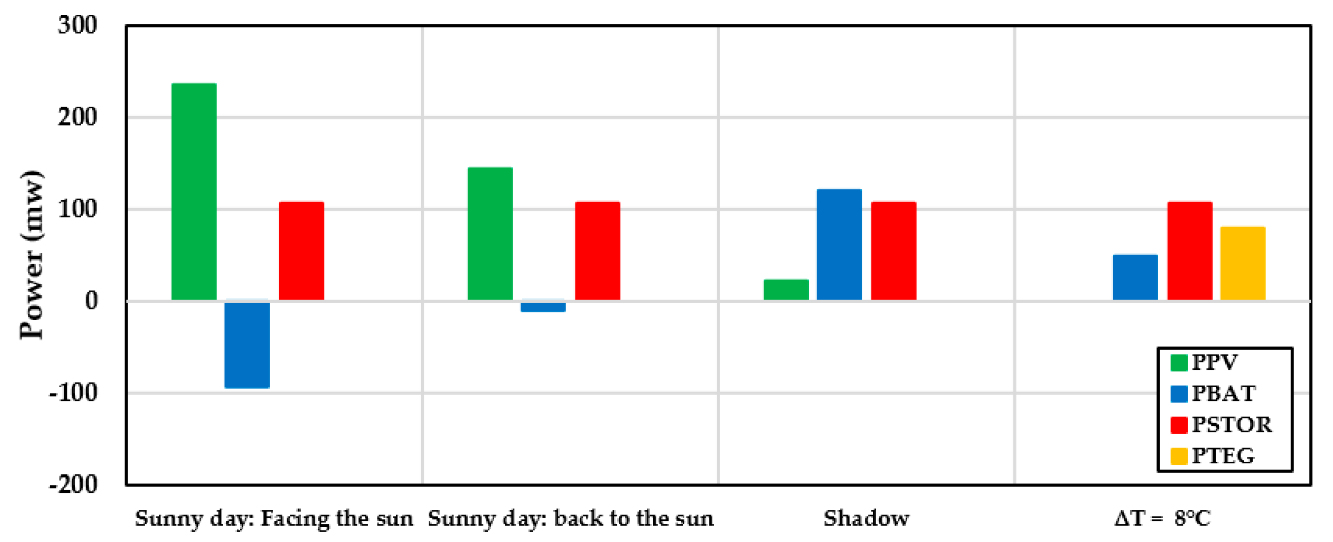
Figures 8 shows the measured power of the PV energy harvester at different hours on 27 and 28 August 2023, 10 minutes, one and two hours, respectively, and for a sunny day, facing the sun, back to the sun and a shadow day where PTEG = 0. According to this comparison, the negative battery power indicates the battery is charging, and the positive battery power means that the battery is being discharged and the power consumption is also provided from the battery.
Since boost-based converters operate in discontinuous conduction mode (DCM), it is difficult to mathematically calculate the average or root mean square (RMS) input current of the BQ25504 converter. And since TI does not publish the internal switching FET capacitances needed to calculate the switching losses, the best way to calculate the losses of the BQ25504 is to measure the input and output power and then calculating the efficiency, as follows:
P I N = P l o s s + P O U T
η = P O U T P I N = i f   P B A T > 0       P O U T = P S T O R P I N = P P V + P T E G + | P B A T | i f   P B A T < 0   P O U T = P S T O R + | P B A T | P I N = P P V + P T E G
The maximum conversion efficiency on a sunny day facing the sun, (ƞ) is 85 %. where ƞ is the ratio of output power to input power. Therefore, the PV energy harvester charges the battery and provides the current consumption of the sensor node. Also, on a sunny day back to the sun, the PV panel alone can support the total power required for sensor node, and it turned into a self-powered system without battery (see Table 3). The maximum conversion efficiency on a sunny day back to the sun, (ƞ) is 80 %.
According to Figure 6, the PV panel cannot provide the total consumption of the sensor node in the shadow day, and therefore, the battery acts as a backup and provides the rest of the consumption power of the sensor node.
Also, Figure 6 shows the TEG module test conditions at a temperature difference of 8 °C where PPV = 0. In this situation, in addition to the TEG module, the battery also feeds part of the system load. The maximum conversion efficiency of the TEG module (ƞ) is 82 %.

3.1.2. Second Experimental Stage: PV Energy Harvesting System under the Various Resistive Loads

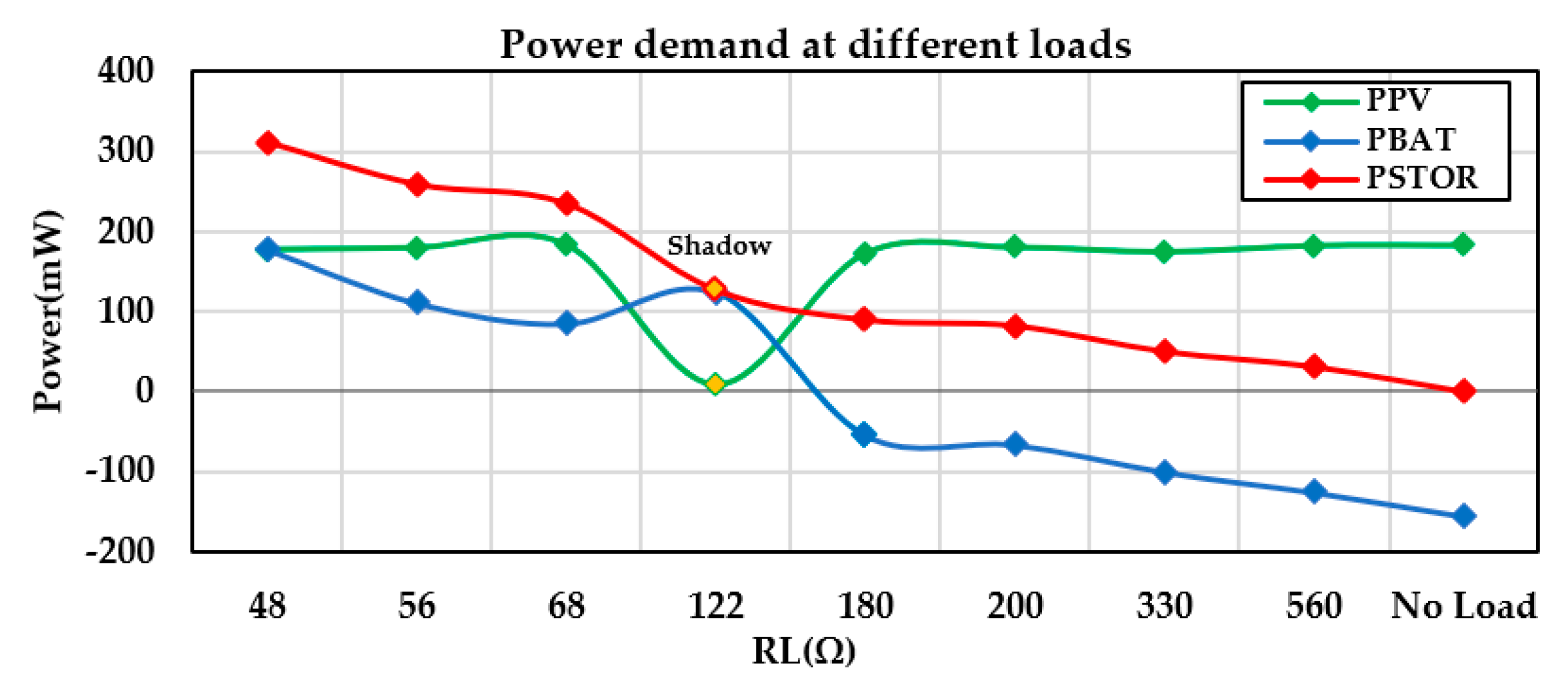
Figure 7 illustrates the values of PV input power, battery power, and output power under various resistive loads on a sunny day. It also shows the person's entering into the shade for a few minutes under specific conditions and then returning to sunlight.
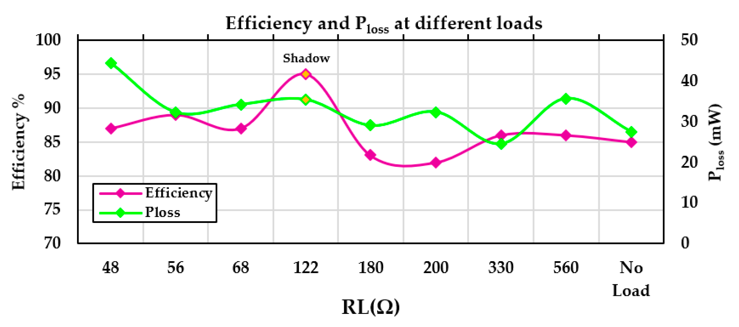
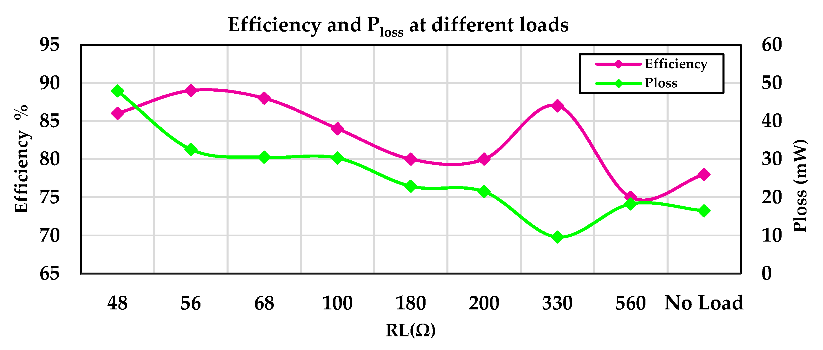
According to the diagram, in the no-load state, the energy harvested from the PV panel is stored in the battery, and then the resistive load values are changed from 31 mW to 312 mW. In five points of this diagram, in addition to supplying the load from the PV energy harvester, the battery is also being charged, and the efficiency is 83%. In the rest of the points, due to the high demand of the load, the battery is being discharged, and the efficiency is 87 %, because the power consumption of the system is also provided by the battery. The efficiency and power losses of the PV energy harvesting system under various resistive loads on sunny days and specifically in shadow conditions are shown in Figure 8.

3.1.3. Third Experimental Stage: TEG Energy Harvesting System under the Various Resistive Loads

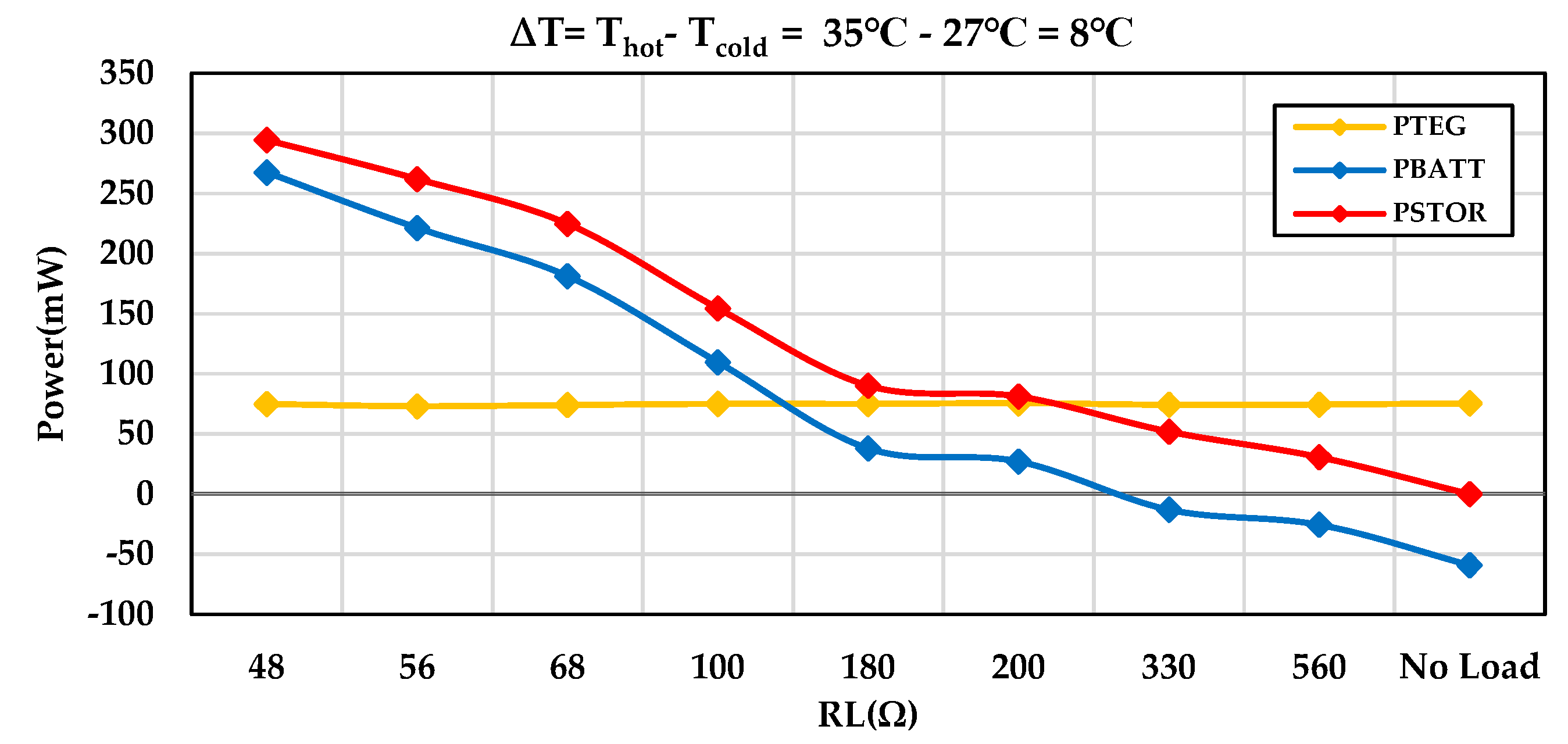
illustrates the values of TEG input power, battery power, and output power under various resistive loads at a temperature difference of 8 °C. According to the diagram, in three points of this diagram, in addition to supplying the load from the TEG modules, the battery is also being charged. The efficiency and power losses of the TEG energy harvesting system under various resistive loads at a temperature difference of 8 °C conditions are shown in Figure 10.

3.1.4. Fourth Experimental Stage: Hybrid Energy Harvesting

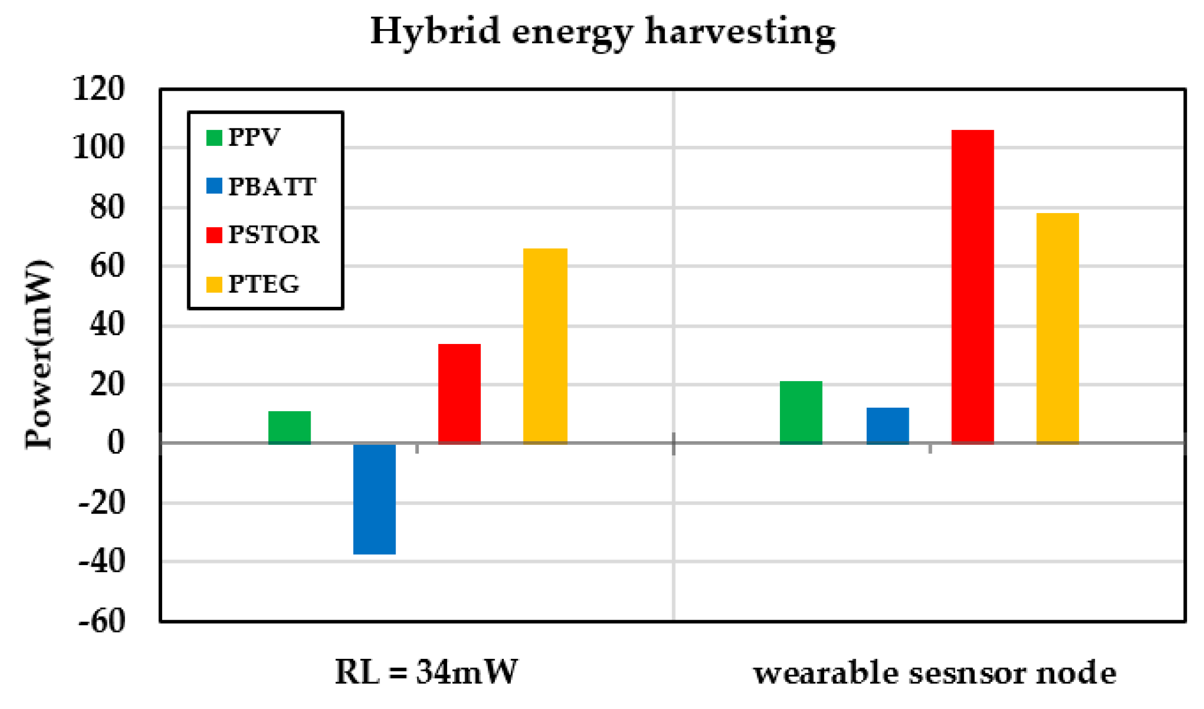
Figure 11 shows the contribution of hybrid energy harvesting sources in shade conditions and a temperature difference of 8 °C to supply wearable sensors node and the load of 34 mW. Under the 34-mW load, in addition to supplying the load, the battery is also charged and the system efficiency is 92 %. Furthermore, the system efficiency with the wearable sensor node is 95%.
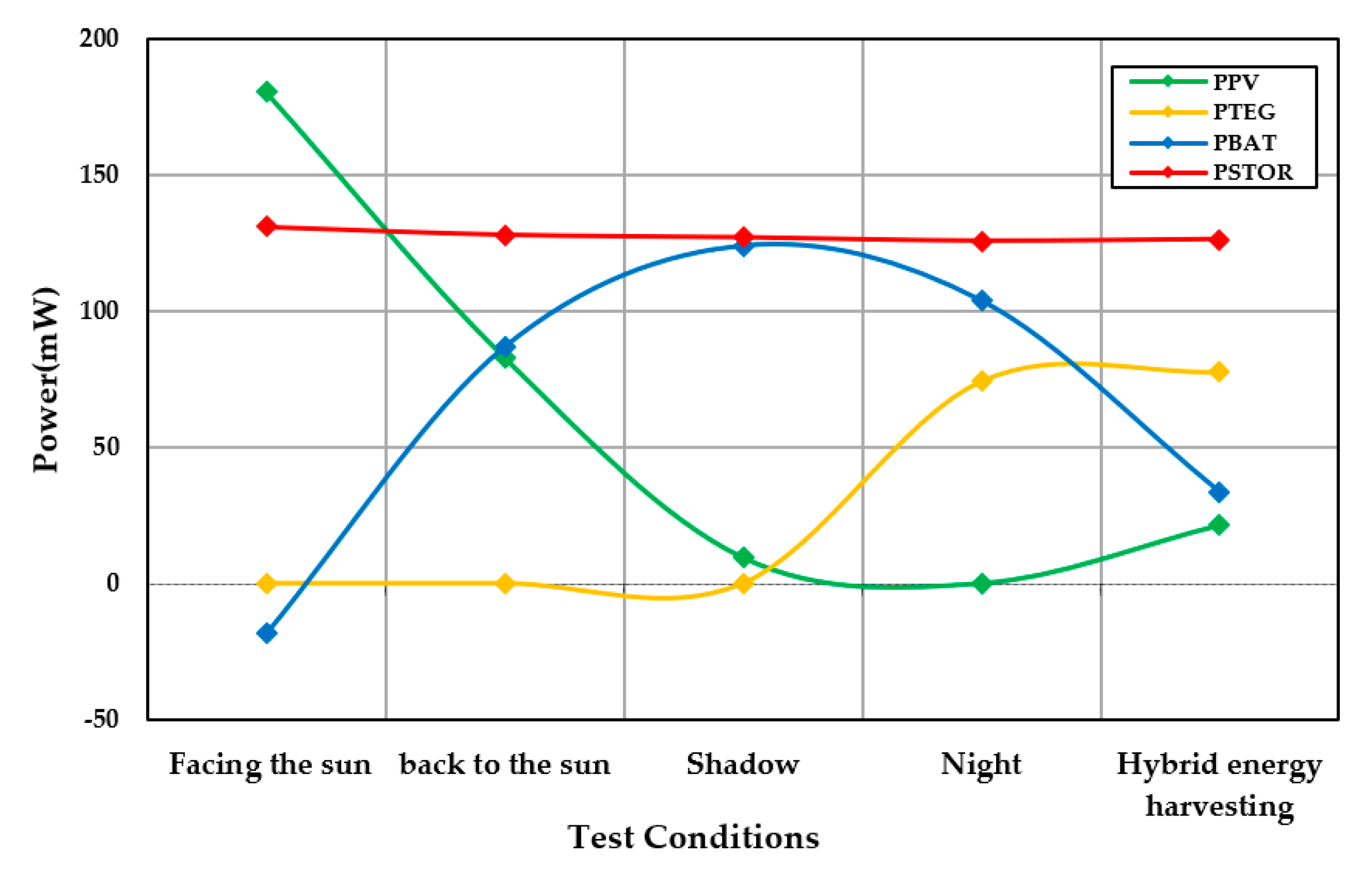
Also, in Figure 12, the hybrid energy harvesting system on a partly cloudy day and temperature difference of 8 °C, for the sensor node of the wearable system, is compared with different conditions of the single energy harvesting system in the sunny day facing the sun, back to the sun, shade and night modes. According to this diagram, MPPT has been achieved in the hybrid structure of both energy harvesting sources.
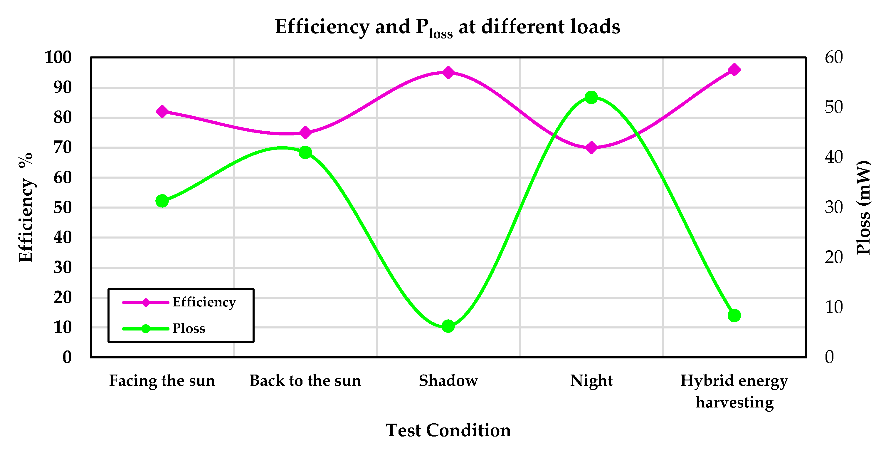
The efficiency and Ploss of the system in different conditions in Figure 12, of sunny day facing the sun, a sunny day with its back to the sun, a shadow day, the TEG module in a temperature difference of 8 °C, and the efficiency of the hybrid energy harvesting system in shadow conditions and a temperature difference of 8 °C are shown in Figure 13. In the shadow condition, the battery provides most of the output power, and as a result, the system efficiency is high, while in the hybrid energy harvesting system, the system efficiency is 96 %, and the battery provides a small part of the consumed power.

4. Discussion

We designed and developed a wearable device for health monitoring in the head/ face and wrist region, focusing on long-term continuous measurement developing a hybrid double source. We mainly targeted people engaged in outdoor activities, such as workers in the oil and gas industry. Given the high-power density of solar cells outdoors, a hybrid of PV and TEG energy is utilized to quickly and sufficiently harvest energy from sunlight and body heat. Since body heat is an inherent part of the human body, TEG can provide a useful energy source for wearable medical devices when sunlight is not available or when a person is inside a building, considering the temperature difference of the available energy source. This improves the temporal-spatial stability and reliability of harvesting system.
The system harvests input powers from PV and TEG sources simultaneously, utilizing two BQ25504 low-power DC/DC boost converters, to supply the load and charge the battery. By eliminating Schottky diodes with high power losses and voltage drops, and only harvesting energy from the source with the higher voltage at any given moment, this structure can enhance the system's performance. Additionally, the PV panel and TEG modules support small form factor and high efficiency, which are essential in providing the ease of use, user experience, and unobtrusiveness of wearable devices.
Table 5 shows the comparison of the proposed hybrid energy harvesting system with the related previous works [28,30,57,58]. In any wearable device, the total dimension and form factor play the pivotal roles in user experiences, useability, and practicability that lead to unobtrusiveness. Thus, careful circuit design and components selection are vital due to the limited space. Considering these points, we tried to reduce the overall area of the PV and TEG energy harvesting system much lower compared to other works Consequently, this can facilitate further wearing wearable devices by users and drive them towards the wear-and-forget. Although, our careful design and components selection resulted in shrinking the size of PV panel and TEG module, but this reduction in dimensions did not decrease the output power of the PV panel and TEG module. The harvesting sources could achieve an appropriate output power from solar sources and body heat, which can support powering medical sensors and wearable medical devices, and store excess harvested energy in batteries – in an ideal condition. The power consumption of the systems depends on various factors, including the types of sensors. The other influencing factor in assessing the total energy consumption is the MCU/embedded system. There are numerous of them which could be well suited for wearable devices. For example, low-power MCUs such as nRF52840 (Nordic Semiconductor, Trondheim, Norway), MSP430FR5969 (Texas Instruments, Dallas, Texas, United States), ADuCM302/ADuCM305 (Analog Devices, Wilmington, Massachusetts) and STM32L4 (STMicroelectronics, Geneva, Switzerland) can extended battery life. However, due to the focus, i.e. the energy harvesting system itself and its suitability of integration in wearable devices, and not the device from one side, and the available and economic expense, we used NodeMCU microcontroller which compared to other microcontrollers with lower power consumption, comparing the total energy consumption is not provided as it could simply be impacted and does not reflect the actual efficiency of the system.
When harvesting energy from multiple sources, some kind of OR-ing structure is needed. This can be done before or after the voltage conversion step [40,41]. While using the first structure has the advantage of using a single voltage converter for both sources, it limits the power sources to having the same internal impedance, and only one source can be used at a time. Therefore, using two BQ25504 ultra-low power boost converters with the same configuration, we made it possible to achieve simultaneous energy harvesting from input sources and separate MPPT for each source, which does not require an additional diode in the output part, and reduces the power loss.
Although continuous measurement of physiological and non-physiological parameters is of concern to all groups of occupations and health, however, some of the targeting group could take the priority due to several reasons such as safety and harsh environmental conditions which expose them in more frequent risks. Workers in the oil and gas industry are of which the continuous monitoring provide them with several advantages. For instance, it is known for its hazardous working conditions, including exposure to toxic chemicals, high-pressure equipment, extreme temperatures, and physically demanding tasks. Wearable health monitors can help identify potential health risks and provide real-time alerts in case of emergencies, enhancing worker safety. Besides, fatigue is a major concern in the industry – not only in oil and gas, but as long working hours can also lead to decreased alertness and cognitive function. Wearable devices can track sleep patterns and activity levels to help employers and workers manage fatigue effectively, reducing the risk of accidents. Additionally, wearable devices can continuously monitor vital signs like HR, body temperature, and respiratory rate. This enables the early detection of health problems such as heat stress, or cardiac issues, allowing for timely intervention and prevention of more serious health events. Monitoring the health of workers in the oil and gas industry through wearables is crucial for enhancing safety, preventing accidents, complying with regulations, and improving overall worker well-being and productivity.
Therefore, considering the condition in which our proposed system is worn by the workers outdoor exposed to the sunlight for two hours (in actual situation of workers in oil and gas industry, the period is longer) the energy consumption of the wearable sensor node is turned into a self-powered system [28]. In this situation, surplus energy is also stored in the battery for times when energy harvesting sources are not available. However, one of our main limitations is evaluating the system in real conditions in the workplace, particularly in the oil and gas industry. Additionally, convincing individuals to wear these glasses during work poses a challenge. The application of this system can be considered not only for workers in the oil and gas industry but also for other individuals such as mountaineers and those interested in health monitoring.
In future work, it is possible to expand the energy harvesting input sources and provide a multi-input hybrid structure (e.g., body motion energy or RF ambient energy). Furthermore, integrating health monitoring sensors such as those for checking blood glucose levels of individuals with diabetes, skin temperature for detecting fever, and more. Additionally, the use of flexible components, which bring a lot of comfort to wearable devices, can be explored.

5. Conclusions

One of the main challenges in continuous and unobtrusive measurement of health-related parameters by wearable biomedical sensors is the battery (capacity and form factor). Energy harvesting techniques (single/multisource) are widely used to extend the lifetime of wearable nodes. We designed and implemented an efficient and hybrid PV/TEG energy harvesting system in a compact form factor, low-cost, and compatible with the wearables in a wide range of wearability, those worn on face, head and wrist regions to prolong the measurement and support the continuous monitoring of physiological parameters. At the core of the system, we utilized two BQ25504 DC/DC boost converters in which both are active and employed simultaneously. The outputs of these converters are paralleled at their two similar circuit nodes: the battery and the load nodes. Consequently, each power source operates with MPPT, as well as they can charge/supply a common battery/load simultaneously or individually. The proposed system is tested for proper operation with experimental results that demonstrate the feasibility of the overall design. During the experimental results, we could increase the lifetime of the sensor system and double of battery lifetime to 18 hours. The efficiency of the proposed hybrid energy harvesting system is 96%. The efficiency of the system resulted in turning the system into a self-power under the direct sunlight for the duration of 2 hours. Our results indicate that the system could be further extended and used in occupations where the user’s workplace is outdoor.

Author Contributions

Conceptualization, Z.T. M.H., and S.D.; methodology, Z.T., M.H., and S.D..; software, Z.T.; validation, Z.T., M.H.; formal analysis, Z.T.; investigation, Z.T.; resources, Z.T.; data curation, Z.T.; writing—original draft preparation, Z.T., M.H., and S.D..; writing—review and editing, Z.T., M.H., M.V., R.S., N.T. and S.D.; visualization, Z.T.; supervision, M.H., and S.D.; project administration, S.D. and M. . All authors have read and agreed to the published version of the manuscript.

Funding

This research received no external funding.

Institutional Review Board Statement

Not applicable.

Informed Consent Statement

Not applicable.

Conflicts of Interest

The authors declare no conflict of interest.

References

  1. Wearable Devices and Explainable Unsupervised Learning for COVID-19 Detection and MonitoringChong YW, Ismail W, Ko K, Lee CY. Energy harvesting for wearable devices: A review. IEEE Sensors Journal. 2019 Jun 28;19(20):9047-62.
  2. Cheong SH, Ng YJ, Lau Y, Lau ST. Wearable technology for early detection of COVID-19: A systematic scoping review. Preventive Medicine. 2022, 22, 107170. [Google Scholar]
  3. Wang WH, Hsu WS. Integrating artificial intelligence and wearable IoT system in long-term care environments. Sensors. 2023, 23, 5913. [Google Scholar] [CrossRef] [PubMed]
  4. Patil V, Singhal DK, Naik N, Hameed BZ, Shah MJ, Ibrahim S, Smriti K, Chatterjee G, Kale A, Sharma A, Paul R. Factors Affecting the Usage of Wearable Device Technology for Healthcare among Indian Adults: A Cross-Sectional Study. Journal of Clinical Medicine. 2022, 11, 7019. [Google Scholar] [CrossRef] [PubMed]
  5. Popov VV, Kudryavtseva EV, Kumar Katiyar N, Shishkin A, Stepanov SI, Goel S. Industry 4.0 and digitalisation in healthcare. Materials. 2022 Mar 14;15(6):2140.
  6. Chong YW, Ismail W, Ko K, Lee CY. Energy harvesting for wearable devices: A review. IEEE Sensors Journal. 2019 Jun 28;19(20):9047-62.
  7. Damre SS, Shendkar BD, Kulkarni N, Chandre PR, Deshmukh S. Smart Healthcare Wearable Device for Early Disease Detection Using Machine Learning. International Journal of Intelligent Systems and Applications in Engineering. 2024;12(4s):158-66.
  8. Guk K, Han G, Lim J, Jeong K, Kang T, Lim EK, Jung J. Evolution of wearable devices with real-time disease monitoring for personalized healthcare. Nanomaterials. 2019 May 29;9(6):813.
  9. Zovko K, Šerić L, Perković T, Belani H, Šolić P. IoT and health monitoring wearable devices as enabling technologies for sustainable enhancement of life quality in smart environments. Journal of Cleaner Production. 2023 Aug 10;413:137506.
  10. Davies HJ, Williams I, Peters NS, Mandic DP. In-ear spo2: A tool for wearable, unobtrusive monitoring of core blood oxygen saturation. Sensors. 2020 Aug 28;20(17):4879.
  11. Hussain Z, Sheng QZ, Zhang WE, Ortiz J, Pouriyeh S. Non-invasive techniques for monitoring different aspects of sleep: A comprehensive review. ACM Transactions on Computing for Healthcare (HEALTH). 2022 Mar 3;3(2):1-26.
  12. Haghi M, Ershadi A, Deserno TM. Recognizing Human Activity of Daily Living Using a Flexible Wearable for 3D Spine Pose Tracking. Sensors. 2023 Feb 12;23(4):2066.
  13. Bellagente P, Crema C, Depari A, Ferrari P, Flammini A, Lanfranchi G, Lenzi G, Maddiona M, Rinaldi S, Sisinni E, Ziliani G. Remote and non-invasive monitoring of elderly in a smart city context. In2018 IEEE sensors applications symposium (SAS) 2018 Mar 12 (pp. 1-6). IEEE.
  14. Razavi M, McDonald A, Mehta R, Sasangohar F. Evaluating Mental Stress Among College Students Using Heart Rate and Hand Acceleration Data Collected from Wearable Sensors. arXiv preprint arXiv:2309.11097. 2023 Sep 20.
  15. Kim J, Khan S, Wu P, Park S, Park H, Yu C, Kim W. Self-charging wearables for continuous health monitoring. Nano Energy. 2021 Jan 1;79:105419.
  16. Nozariasbmarz A, Collins H, Dsouza K, Polash MH, Hosseini M, Hyland M, Liu J, Malhotra A, Ortiz FM, Mohaddes F, Ramesh VP. Review of wearable thermoelectric energy harvesting: From body temperature to electronic systems. Applied Energy. 2020 Jan 15;258:114069.
  17. Hesham R, Soltan A, Madian A. Energy harvesting schemes for wearable devices. AEU-International Journal of Electronics and Communications. 2021 Aug 1;138:153888.
  18. Davies HJ, Bachtiger P, Williams I, Molyneaux PL, Peters NS, Mandic DP. Wearable in-ear PPG: Detailed respiratory variations enable classification of COPD. IEEE Transactions on Biomedical Engineering. 2022 Jan 25;69(7):2390-400.
  19. Haghi M, Danyali S, Thurow K, Warnecke JM, Wang J, Deserno TM. Hardware prototype for wrist-worn simultaneous monitoring of environmental, behavioral, and physiological parameters. Applied Sciences. 2020 Aug 7;10(16):5470.
  20. Haghi M, Danyali S, Ayasseh S, Wang J, Aazami R, Deserno TM. Wearable devices in health monitoring from the environmental towards multiple domains: A survey. Sensors. 2021 Mar 18;21(6):2130.
  21. He Z, Wang K, Zhao Z, Zhang T, Li Y, Wang L. A Wearable Flexible Acceleration Sensor for Monitoring Human Motion. Biosensors. 2022 Aug 10;12(8):620.
  22. Babar M, Rahman A, Arif F, Jeon G. Energy-harvesting based on internet of things and big data analytics for smart health monitoring. Sustainable Computing: Informatics and Systems. 2018 Dec 1;20:155-64.
  23. Páez-Montoro A, García-Valderas M, Olías-Ruíz E, López-Ongil C. Solar energy harvesting to improve capabilities of wearable devices. Sensors. 2022 May 23;22(10):3950.
  24. Proto A, Bibbo D, Cerny M, Vala D, Kasik V, Peter L, Conforto S, Schmid M, Penhaker M. Thermal energy harvesting on the bodily surfaces of arms and legs through a wearable thermo-electric generator. Sensors. 2018 Jun 13;18(6):1927.
  25. Huet F, Boitier V, Seguier L. Tunable piezoelectric vibration energy harvester with supercapacitors for WSN in an industrial environment. IEEE Sensors Journal. 2022 Jun 28;22(15):15373-84.
  26. Gljušćić P, Zelenika S, Blažević D, Kamenar E. Kinetic energy harvesting for wearable medical sensors. Sensors. 2019 Nov 12;19(22):4922.
  27. Sherazi HH, Zorbas D, O’Flynn B. A comprehensive survey on RF energy harvesting: Applications and performance determinants. Sensors. 2022 Apr 13;22(8):2990.
  28. Mohsen S, Zekry A, Youssef K, Abouelatta M. A self-powered wearable wireless sensor system powered by a hybrid energy harvester for healthcare applications. Wireless Personal Communications. 2021 Feb;116(4):3143-64.
  29. Bai Y, Jantunen H, Juuti J. Energy harvesting research: the road from single source to multisource. Advanced materials. 2018 Aug;30(34):1707271.
  30. Shi Y, Wang Y, Mei D, Feng B, Chen Z. Design and fabrication of wearable thermoelectric generator device for heat harvesting. IEEE Robotics and Automation Letters. 2017 Jul 31;3(1):373-8.
  31. Xiao L, Wu K, Tian X, Luo J. Activity-specific caloric expenditure estimation from kinetic energy harvesting in wearable devices. Pervasive and Mobile Computing. 2020 Sep 1;67:101185.
  32. Pillatsch P, Yeatman EM, Holmes AS. Real world testing of a piezoelectric rotational energy harvester for human motion. InJournal of Physics: Conference Series 2013 Dec 4 (Vol. 476, No. 1, p. 012010). IOP Publishing.
  33. Delnavaz A, Voix J. Energy harvesting for in-ear devices using ear canal dynamic motion. IEEE Transactions on Industrial Electronics. 2013 Jan 25;61(1):583-90.
  34. Li X, Sun Y. WearETE: A scalable wearable e-textile triboelectric energy harvesting system for human motion scavenging. Sensors. 2017 Nov 17;17(11):2649.
  35. Farooq M, Sazonov E. Segmentation and characterization of chewing bouts by monitoring temporalis muscle using smart glasses with piezoelectric sensor. IEEE journal of biomedical and health informatics. 2016 Dec 14;21(6):1495-503.
  36. Yu BY, Wang ZH, Ju L, Zhang C, Liu ZG, Tao L, Lu WB. Flexible and wearable hybrid RF and solar energy harvesting system. IEEE Transactions on Antennas and Propagation. 2021 Oct 14;70(3):2223-33.
  37. Veloo SG, Tiang JJ, Muhammad S, Wong SK. A Hybrid Solar-RF Energy Harvesting System Based on an EM4325-Embedded RFID Tag. Electronics. 2023 Sep 27;12(19):4045.
  38. J Noh YS, Seo JI, Kim HS, Lee SG. A reconfigurable DC/DC converter for maximum thermoelectric energy harvesting in a battery-powered duty-cycling wireless sensor node. IEEE Journal of Solid-State Circuits. 2022 Mar 7;57(9):2719-30.
  39. Ali A, Shaukat H, Bibi S, Altabey WA, Noori M, Kouritem SA. Recent progress in Energy Harvesting Systems for wearable technology. Energy Strategy Reviews. 2023 Sep 1;49:101124.
  40. Tan YK, Panda SK. Energy harvesting from hybrid indoor ambient light and thermal energy sources for enhanced performance of wireless sensor nodes. IEEE Transactions on Industrial Electronics. 2010 Dec 23;58(9):4424-35.
  41. Carli D, Brunelli D, Benini L, Ruggeri M. An effective multi-source energy harvester for low power applications. In2011 Design, Automation & Test in Europe 2011 Mar 14 (pp. 1-6). IEEE.
  42. Ngoc-Thang B, Nguyen TM, Truong TT, Nguyen BL, Nguyen TT. A dynamic reconfigurable wearable device to acquire high quality PPG signal and robust heart rate estimate based on deep learning algorithm for smart healthcare system. Biosensors and Bioelectronic.
  43. Longmore SK, Lui GY, Naik G, Breen PP, Jalaludin B, Gargiulo GD. A comparison of reflective photoplethysmography for detection of heart rate, blood oxygen saturation, and respiration rate at various anatomical locations. Sensors. 2019 Apr 19;19(8):1874.
  44. MAX30102 Datasheet and Product Info | Analog Devices, High-Sensitivity Pulse Oximeter and Heart-Rate Sensor for Wearable Health. https://www.analog.com/en/products/max30102.html.
  45. Yang CC, Hsu YL. A review of accelerometry-based wearable motion detectors for physical activity monitoring. Sensors. 2010 Aug 20;10(8):7772-88.
  46. He Z, Wang K, Zhao Z, Zhang T, Li Y, Wang L. A Wearable Flexible Acceleration Sensor for Monitoring Human Motion. Biosensors. 2022 Aug 10;12(8):620.
  47. MPU-6050 | TDK InvenSense, TDK InvenSense, Nov. 28, 2022. https://invensense.tdk.com/products/motion-tracking/6-axis/mpu-6050/.
  48. AEM10941 Solar Energy Harvesting IC, e-peas | Mouser. https://www.mouser.com/new/e-peas/e-peas-aem10941-solar-energy-harvesting-ic/.
  49. AEM20940 Thermal Energy Harvesting IC, e-peas | Mouser. https://www.mouser.com/new/e-peas/e-peas-aem20940-thermal-energy-harvesting-ic/.
  50. ADP5091 Datasheet and Product Info | Analog Devices. https://www.analog.com/en/products/adp5091.html.
  51. BQ25504 data sheet, product information and support | TI.com. https://www.ti.com/product/BQ25504.
  52. BQ25570 data sheet, product information and support | TI.com. https://www.ti.com/product/BQ25570.
  53. SPV1050 - STMicroelectronics, STMicroelectronics. https://www.st.com/en/power-management/spv1050.html.
  54. LTC3105 Datasheet and Product Info | Analog Devices. https://www.analog.com/en/products/ltc3105.html.
  55. LTC3106 Datasheet and Product Info | Analog Devices. https://www.analog.com/en/products/ltc3106.html.
  56. Huynh DC, Dunnigan MW. Development and comparison of an improved incremental conductance algorithm for tracking the MPP of a solar PV panel. IEEE transactions on sustainable energy. 2016 Apr 20;7(4):1421-9.
  57. Guragain DP, Budhathoki RK, Ghimire P. Programmable timer triggered energy harvesting wireless sensor-node using long range radio access technology. International Journal of Electrical & Computer Engineering (2088-8708). 2022 Aug 1;12.
  58. Magno M, Brunelli D, Sigrist L, Andri R, Cavigelli L, Gomez A, Benini L. InfiniTime: Multi-sensor wearable bracelet with human body harvesting. Sustainable Computing: Informatics and Systems. 2016 Sep 1;11:38-49.
Figure 1. Block Diagram of the Energy Harvesting System [28].
Preprints 102195 g001
Figure 2. (a) The Block diagram of the hybrid energy harvesting system; (b) Proposed development of the hybrid energy harvesting system.
Preprints 102195 g002
Figure 3. Comparison of several examples of commercial energy harvesting ICs used for PV/TEG energy sources.
Preprints 102195 g003
Figure 4. The proposed multi-port energy harvesting system.
Preprints 102195 g004
Figure 5. circuit schematic of the BQ25504 ultra-low-power DC/DC boost converter.
Preprints 102195 g005
Figure 6. Exchange of PV/TEG power, battery and wearable sensor node power in different weather conditions.
Preprints 102195 g006
Figure 7. The power demand of the PV energy harvesting system under the various resistive loads.
Preprints 102195 g007
Figure 8. Efficiency and power losses of the PV energy harvesting system under various resistive loads.
Preprints 102195 g008
Figure 9. The power demand of the TEG energy harvesting system under the various resistive loads.
Preprints 102195 g009
Figure 10. Efficiency and power losses of the TEG energy harvesting system under various resistive loads.
Preprints 102195 g010
Figure 11. The contribution of hybrid energy harvesting resources in supplying the output load, in shadow conditions.
Preprints 102195 g011
Figure 12. Power contribution of hybrid energy harvesting system for wearable sensor node.
Preprints 102195 g012
Figure 13. Energy harvesting system efficiency and Ploss.
Preprints 102195 g013
Table 1. Power Densities of Different Energy Sources [6].
Energy sources Power density
Ambient light 100 mW/cm2 (direct sun)
100 μW/cm2 (indoor illumination)
Thermoelectric 60 μW/cm2
Radio frequency 1 μW/cm2 (ambient)
15 μW (external)
Human 1000 μW/cm2 (biochemical)
4 μW/cm3 (biomechanical - microgenerator)
200 μW/cm3 (biomechanical - piezoelectric)
Table 2. KXOB25-05X3F Electrical Characteristics.
Symbol Cell Parameter Typical Ratings1
VOC open circuit voltage 2.07 V
ISC short circuit current 19.5 mA
Vmpp voltage at MPP 1.67 V
Impp current at MPP 18.4 mA
Pmpp maximum peak power 30.7 mW
H Solar cell efficiency 25%
Table 3. 1MC06-126-03TEG Performance data.
Symbol Parameter Values at Hot Side Temperature
35°C 55°C 85°C
Tcold Cold Side Temperature, (°C) 27 27 27
Optη Optimum Efficiency, (%) 0.40 1.36 2.71
POPT Optimum Power, (mW) 20 233 964
VOPT Optimum Voltage, (V) 0.244 0.868 1.825
VOC Open Circuit Voltage, (V) 0.43 1.51 3.18
ISC Short Circuit Current, (A) 0.19 0.63 1.24
Table 4. Details of TEG module testing conditions in temperature difference ∆T= Thot- Tcold = 35 ℃ - 27 ℃ = 8 ℃.
Test Conditions Indoor
10 min 1 hour
VTEG (V) 0.96 0.96
ITEG (mA) 82.2 82.2
PTEG (mW) 78.912 78.912
VBATT (V) 3.93 3.92
Iavrage (mA)1 32.21 33.21
Skin temperature 35 35
Environment temperature 27 27
1[(ISTOR-ON × Tactive-Sensor) + (ISTOR-OFF × Tsleep-Sensor)] /T.
Table 5. Comparison of the current work with some previous studies.
ref Energy Source Sensors deployed Energy Storage Area of harvester (mm2) Power of harvester (mW) mode of device wearability Energy Management IC MCU unit Circuit Techniques for Hybrid
This work PV, TEG PPG, Accelerometer Battery, 300mAh Panel = 1840, TEG = 1024 Panel = 307, TEG = 78.2 at (∆T = 8 °C) Glasses, Wrist-worn Two BQ25504 Boost Converter NodeMCU ESP8266 energy harvesting from both sources, without diode
[28] PV, TEG Tmperature Sensor, pulse oximeter sensor, and accelerometer sensor Super-capacitor, 50F Panel = 4320, TEG = 1600 Panel = 207, TEG = 50 at (∆T = 20 °C) Wrist-worn LTC3105 Bosst Converter ATmega-328p Power OR-ing.
[30] TEG powering a LED N/A TEG = 559 TEG = 0.023 at (∆T = 10 °C) Wrist-worn LTC3108 Boost Converter N/A __
[57] PV N/A Battery, CR2025- super-capacitor, 4F 40000 820 N/A BQ25570 Buck-Boost Converter Atmel ATMEGA328P-AU __
[58] PV, TEG Nano-power accelerometer, a temperature sensor and an analog microphone Battery, 40mAh Panel = 3892, TEG = 560 Panel = 4.42, TEG = 2.62 at (∆T = 16°C) bracelet BQ25570 Buck-Boost Converter and LTC3108 Boost Converter MSP430FR5969 energy harvesting from both sources, with diode
Disclaimer/Publisher’s Note: The statements, opinions and data contained in all publications are solely those of the individual author(s) and contributor(s) and not of MDPI and/or the editor(s). MDPI and/or the editor(s) disclaim responsibility for any injury to people or property resulting from any ideas, methods, instructions or products referred to in the content.
Copyright: This open access article is published under a Creative Commons CC BY 4.0 license, which permit the free download, distribution, and reuse, provided that the author and preprint are cited in any reuse.
Prerpints.org logo

Preprints.org is a free preprint server supported by MDPI in Basel, Switzerland.

Subscribe

© 2024 MDPI (Basel, Switzerland) unless otherwise stated