Preprint
Article

Theory of Majorana–Type Heavy Ion Double Charge Exchange Reactions by Pion-Nucleon Isotensor Interactions

Altmetrics

Downloads

96

Views

18

Comments

0

A peer-reviewed article of this preprint also exists.

Submitted:

28 March 2024

Posted:

28 March 2024

You are already at the latest version

Alerts
Abstract
The theory of heavy ion double charge exchange (DCE) reactions proceeding by effective rank–2 isotensor interactions is presented. Virtual pion–nucleon charge exchange interactions are investigated as the source for induced isotensor interactions, giving rise to the Majorana DCE (MDCE) reaction mechanism. MDCE is of a generic character, proceeding through pairs of complementary (π±,π∓) reactions in the projectile and target nucleus. The dynamics of the elementary processes is discussed where the excitation of pion–nucleon resonances are of central importance. Investigations of initial and final state ion–ion interactions show that these effects are acting as vertex renormalizations. In closure approximation, well justified by the finite pion mass, the second order transition matrix elements reduce to pion potentials and effective two–body isotensor DCE interactions, giving rise also to two–body correlations in either of the participating nuclei. Connections to neutrinoless Majorana double beta decay (MDBD) are elucidated at various levels of dynamics, from the underlying fundamental electro–weak and QCD scales to the physical scales of nuclear MDBD and MDCE physics. It is pointed out that heavy ion MDCE reactions may also proceed by competing electro–weak charge exchange processes, leading to lepton MDCE by electrons, positrons, and neutrinos.
Keywords: 
Subject: Physical Sciences  -   Nuclear and High Energy Physics
Contents
Preprints 102517 i001
Preprints 102517 i002
Preprints 102517 i003

1. Introduction

Heavy ion double charge exchange (DCE) reactions are unique as a new tool for investigations of the rather unexplored sector of higher order nuclear dynamics. DCE research is of generic interest for nuclear reaction and nuclear structure physics because of its large potential for high precision investigations of nuclear modes which otherwise are almost impossible to access. A central topic of this article is to show that DCE physics is going significantly beyond the standard approach to peripheral heavy ion reactions as dominated by mean–field dynamics. DCE research is located at the intersection of nuclear and hadron physics, thus broadening the view on the dynamics of nuclear many–body systems.
In a previous paper [1] the emergence of an effective isotensor interaction and the role of ion–ion elastic interactions in second order double single charge exchange (DSCE) reactions were investigated. DSCE reactions proceed by acting twice with the nucleon–nucleon (NN) isovector T–matrix where each of the actions generates a single charge exchange (SCE) transition. It was shown that by proper transformations of the operator structures, defined by central spin–scalar, spin–vector and rank–2 spin tensor interactions, effective operators are obtained, acting as rank–2 isotensor operators intrinsically in each nucleus. In addition, in [1] the role of initial state (ISI) and final state (FSI) ion–ion elastic interactions was investigated. The DSCE investigations led to three significant and far reaching result:
  • ISI and FSI interactions lead to distortion coefficients which act as quenching factors. As a result the DSCE reaction amplitude and consequently the observed DSCE nuclear matrix elements are strongly suppressed by orders of magnitudes compared to the results expected without ISI/FSI.
  • The relative motion degree of freedom induces in DSCE reactions in each nucleus correlation between the pair of SCE vertices where the correlation length is determined by the kinematical conditions of the reaction.
  • The two pairs of NN T–matrices can be recast into a set of spin–scalar and spin–vector rank–2 isotensor interactions, acting in each nucleus as effective two–body interactions and forming together a four–body ion–ion interaction.
In this work, we investigate the competing Majorana DCE (MDCE) scenario. While DSCE theory is the second order extension of conventional direct reaction single charge exchange (SCE) theory [2,3], MDCE theory takes a completely different view by describing a heavy ion DCE reaction as a combination of pion-nucleon DCE reactions in projectile and target nucleus. A consequence of such an approach is that the second order aspects inherent to a DCE reaction are treated on the level of isovector pion-nucleon scattering, giving rise to dynamically created effective rank–2 isotensor interactions in projectile and target nucleus.
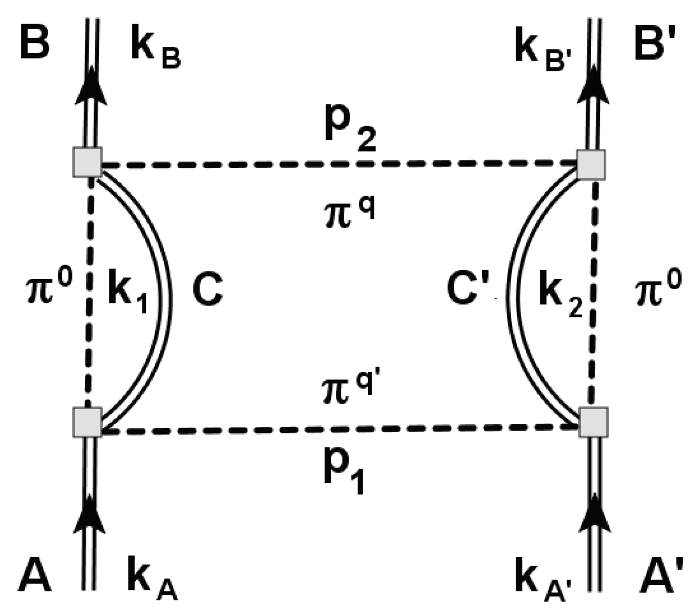
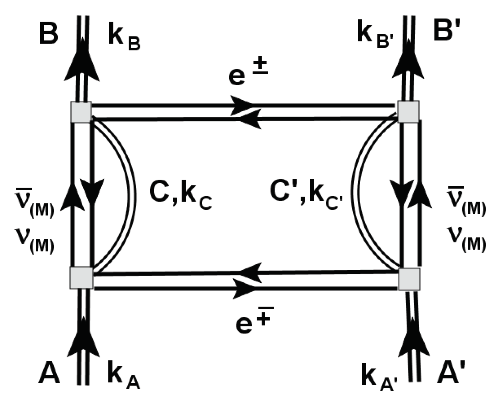
By definition, a heavy ion DCE reaction relies finally on an interaction of rank–2 isotensor character. Hitherto searches for such a kind of nuclear interaction of generic character have been unsuccessful. Until today, neither the existence of elementary isotensor mesons [4,5,6] nor signatures of interactions of that kind in single, isolated nuclei [7] could be confirmed with convincing certainty. Most likely rank–2 isotensor interactions do not exist as an elementary mode of its own right. The conditions, however, might change if two nuclei are in close contact as in a peripheral ion–ion collision. In such a situation, an effective isotensor interaction can be generated dynamically as a transient phenomenon. The MDCE interaction process is illustrated graphically in Figure 2: MDCE reactions proceed by virtual pion–nucleon double charge exchange scattering, involving sequences of π ± , π 0 and π 0 , π ± pion–nucleon SCE reactions. Their proper combination leads finally to virtual ( π ± , π ) pion–nucleon DCE reactions in the reacting nuclei. Under nuclear structure aspects a DCE reaction is determined by excitations of n 2 p 2 and p 2 n 2 two particle–two hole configurations in the interacting nuclei.
In the past pion beams have been used extensively for DCE research on nuclei at the Los Alamos Meson Physics Facility (LAMPF) [8]. LAMPF was shut down a long time ago but the physics issues studied there have become of new interest for heavy ion DCE research. The theoretical understanding achieved at that time for pion–nucleon isovector dynamics [9,10,11,12,13,14] and DCE nuclear structure theory [15,16,17,18,19] are worth to be rediscovered because they are of high value for research on the MDCE mechanism of heavy DCE reactions.
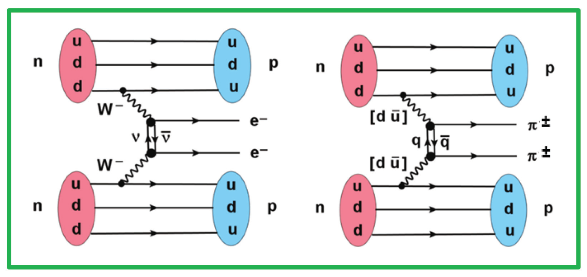
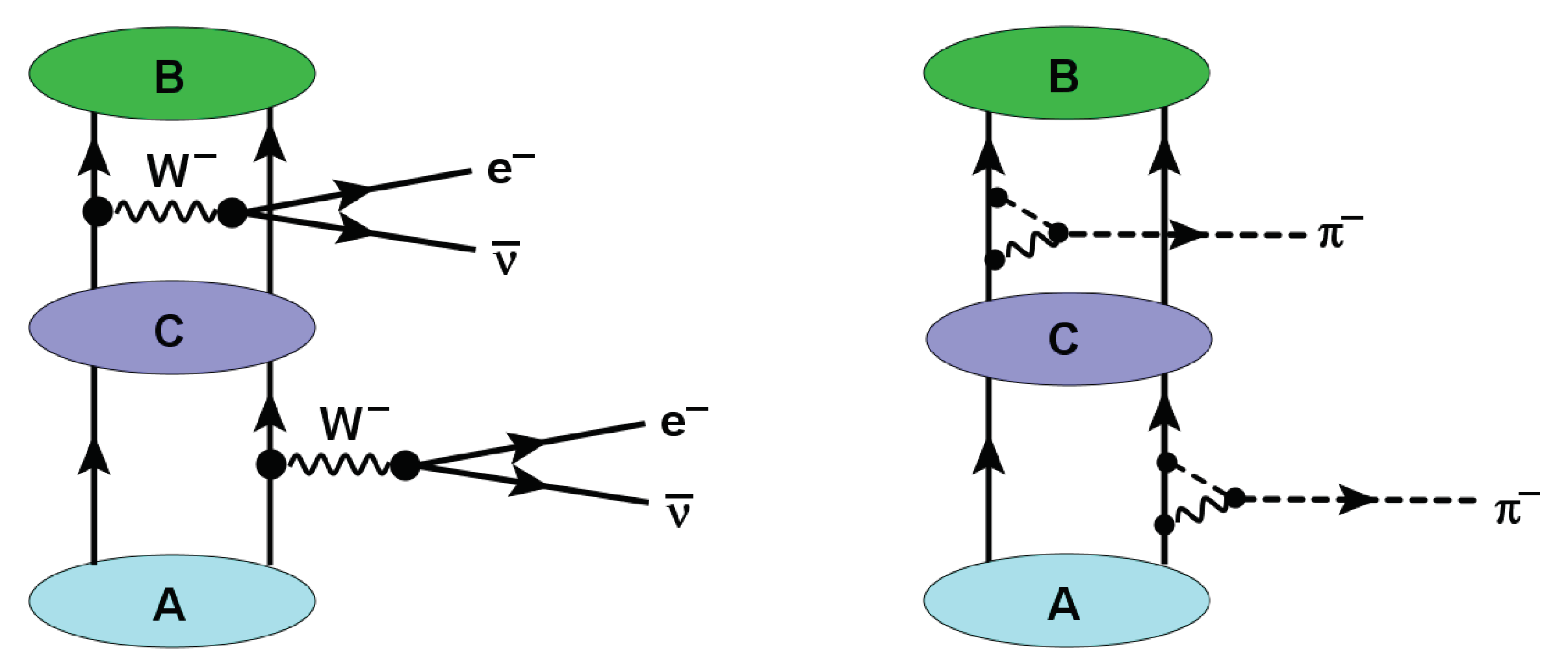
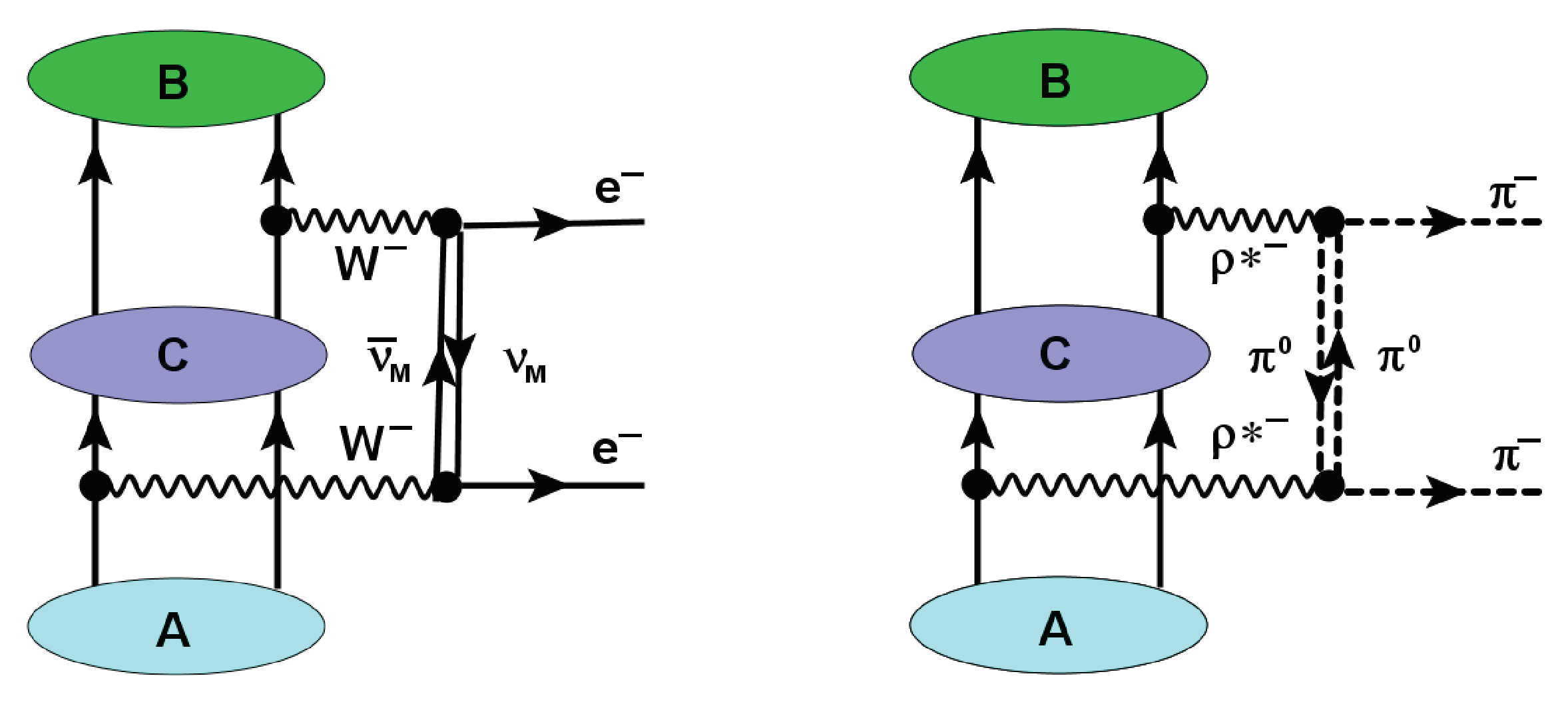
In [1,20] the similarity of DSCE and two–neutrino DBD was emphasized. A special aspect of the pionic MDCE scenario is the striking similarity to the heavily discussed neutrinoless Majorana DBD (MDBD). That similarity is illustrated in Figure 1 on the elementary level of virtual weak W ± gauge bosons and highly virtual quark–antiquark q q ¯ modes, the former materializing into a lepton pair on the mass–shell, the latter into a pair of meson off the mass–shell. MDBD is searched for as a possible signature for physics beyond the standard model (BSM) because MDBD relies on the still hypothetical Majorana neutrinos with the claimed property ν M ν ¯ M , see e.g. [21,22]. MDBD would lead to the spontaneous creation of matter in form of lepton pairs, thus violating lepton number conservation. As will be seen,the MDCE mechanism is described by graphs resembling those of neutrinoless DBD. However, MDCE is determined finally by strong hadronic interactions of a quite different range and strength. Spectroscopically the same nuclear states as in MDBD are involved and the transitions are induced by the same kind of isovector multipole operators, exciting spin-scalar and spin–vector modes.
Figure 1. Comparison of the elementary mechanisms underlying weak neutrinoless Majorana double beta decay (MDBD) (left), leading to the creation of a lepton pair on the mass–shell, and strong Majorana double charge exchange (MDCE) leading to the emission of a pair of virtual mesons off the mass–shell. See text for further discussions.
Preprints 102517 g001
Figure 2. The MDCE diagram for the reaction A ( Z , N ) + A ( Z , N ) B ( Z ± 2 , N 2 ) + B ( Z 2 , N ± 2 ) . The isovector pion–nucleon T–matrices are denoted by filled gray boxes. The intermediate neutral pions induce a correlation between the SCE events, thus making MDCE a two–nucleon process. The co–propagating core states are denoted by C = C ( Z ± 1 , N 1 ) and C = C ( Z 1 , N ± 1 ) . Charged pions π q and π q , q , q = ± 1 are exchanged with four–momenta p 1 , 2 between the nuclei. The four–momenta in the incident ( k A , A ), the intermediate ( k 1 , 2 ), and the exit channel ( k B , B ) are indicated.
Preprints 102517 g002
In the forthcoming sections we present a concise, unified picture of the physics of MDCE dynamics and the relation to neutrinoless Majorana double beta decay (MDBD). The theoretical foundations and methods are discussed much beyond the level presented in previous publications [3,23]. The overall aspects, the essential features, and theoretical principles of MDCE reaction physics are presented in Section 2. As mentioned before, the MDCE reaction amplitude is formally given by an one–step distorted wave matrix element. The quenching of reaction yields caused by the strongly absorptive ion–ion optical potential discussed in [1] for the DSCE amplitude is less pronounced but still a highly important effect of significant strength. Therefore, the role of ISI and FSI is elucidated in Section 3. A different view on ISI and FSI as vertex renormalization is presented in Section 4 where we point to the formal similarity of ISI/FSI with the treatment of short–range correlations in nuclear structure calculations, used especially also in DBD theory. The MDCE transition form factors and nuclear matrix elements are investigated in Section 5. There we also address in some detail the essential features of the box diagram, introduce the closure approximation, which allows to define second order pion potentials as effective 2–body DCE interactions. Pion–nucleon scattering and the construction of the pion–nucleon T-matrix, used to describe the excitation of n p 1 and p n 1 states, are the subjects of Section 6. Illustrating numerical results are presented in Section 7. Connections of DCE reactions to DBD are discussed in Section 8. A summary and an outlook is found in Section 9. Additional material on distortion amplitudes, details of the box diagram, the pion–nucleon T–matrix, and more on the theoretical background of the pion potentials is presented in several appendices.

2. Theory of Heavy Ion MDCE Reactions

2.1. Reaction Theoretical Aspects

The differential cross section of a MDCE reaction A ( Z , N ) + A ( Z , N ) B ( Z ± 2 , N 2 ) + B ( Z 2 , N ± 2 ) for unpolarized beam and target nuclei is defined as
d σ α β ( 1 ) = m α m β ( 2 π 2 ) 2 k β k α 1 ( 2 J a + 1 ) ( 2 J A + 1 ) M a , M A α ; M b , M B β M α β ( 1 ) ( k α , k β ) 2 d Ω α β ,
where M α β ( 1 ) is a first order distorted wave (DW) reaction amplitude. The cross section is averaged over the initial nuclear spin states ( J a , A , M a , A ) and summed over the final nuclear spin states ( J b , B , M b , B ), respectively. Reduced masses in the incident and exit channel, respectively, are denoted by m α , β . k α and k β are the (Lorentz–invariant) momenta in the incident and exit channel, respectively.
Formally, the reaction amplitude has the structure of a first order distorted wave matrix element. In r–space formulation the MDCE amplitude is given by
M α β ( 1 ) ( k α , k β ) = χ β ( ) | R α β | χ α ( + ) = d 3 r α d 3 r β χ β ( ) * ( r β ) R α β ( r α , r β ) χ α ( + ) ( r α ) .
The distorted waves χ α , β ( ± ) with asymptotically outgoing and incoming spherical waves, respectively, depend on the invariant channel momenta k α , β and the channel coordinates r α , β , the latter describing the relative distance between the initial nuclei A , A and the final nuclei B , B , respectively. The reaction is described in the ion–ion rest frame.
The distorted waves are of central importance for the quantitative description of direct nuclear reactions like heavy ion SCE and DCE scattering. They account for diffractive and dispersive initial state and final state elastic ion–ion interactions. In Direct Reaction (DR) theory, they are described globally by complex–valued optical model potentials including the long–range Coulomb potential and real and imaginary nuclear potentials of ranges which are defined by the sizes of the density distribution of the colliding nuclei. A key role is played by the strong imaginary parts. They describe the absorption of probability flux by the coupling to the multitude of non–elastic channels and as such are essential for a realistic description of magnitudes of SCE and DCE cross sections and shapes of the related angular distributions, see e.g [24]. As stated in [25] a proper treatment of distortion effects was badly missed in the theory of pion–DCE, leaving many open questions for a realistic description of pion DCE data.
The spectroscopic content of the DCE reaction is contained in the transition kernel R α β . An instructive and successful approach is to use the momentum representation:
R α β ( r α , r β ) = d 3 p 1 ( 2 π ) 3 d 3 p 2 ( 2 π ) 3 e i ( p 1 · r α + p 2 · r β ) F α β ( p 1 , p 2 ) .
As a remarkable first achievement we have succeeded to separate the nuclear and relative motion degrees of freedom. The latter are represented by the plane waves depending on the relative ion–ion coordinates in the incident and the exit channel, denoted by r α and r β , respectively. The MDCE transition form factor
F α β ( p 1 , p 2 ) = W A B ( p 1 , p 2 ) D π q π q ( p 1 , p 2 ) W A B ( p 1 , p 2 ) ,
defined by the diagram of Figure 2 contains as key elements the nuclear transition matrix elements (TME)
W A B ( p 1 , p 2 ) = B | T π N ( p 2 , k | σ 3 ) G A ( k 1 ) T π N ( p 1 , k | σ 1 ) | A ,
W A B ( p 1 , p 2 ) = B | T π N ( p 2 , k | σ 4 ) G A ( k 2 ) T π N ( p 1 , k | σ 2 ) | A .
The TME are of central interest for DCE research because they account for the spectroscopy of the reaction. For example, the transition A B is induced by two consecutive actions of the pion–nucleon isovector T–matrices T π N , each giving rise to a SCE transition, A C and C B , respectively. The vertices are connected by the Green’s function G A ( k 1 ) , describing the s–channel propagation, i.e. in direction of the left and right vertical branches of Figure 2, of the intermediate π 0 + C system. The transition A B follows the same rules. The TME will be investigated in more detail in a later section.
The DCE process is driven by the t–channel exchange of charged pions between the projectile and the target nucleus, as indicated by the lower and upper horizontal branches in Figure 2. In lowest order the exchange is described by the the symmetrized product propagator
D π q π q ( p 1 , p 2 ) 1 2 D π q ( p 1 ) D π q ( p 2 ) + D π q ( p 2 ) D π q ( p 1 ) .
Possible pion–pion and pion–matter interactions are neglected. As discussed in Appendix B in the ion–ion rest frame the four–momentum p 1 = ( 0 , p 1 ) T , p 1 2 = p 1 2 is purely space-like while p 2 = ( E A E B , p 2 ) T includes the reaction Q–value. For | E A E B | m π we may safely neglect the Q–value dependence and describe the exchange of both mesons by static pion propagators
D π q ( p ) = m π p 2 + m π q 2 .
In the ion–ion rest frame and at the energies relevant for heavy ion MDCE reactions the isovector pion–nucleon T-matrix T π N is described adequately by the operator structure [26,27]
T π N ( p , p | σ ) = T 0 ( S π n ) + 1 m π 2 T 1 ( s π n ) p · p + i T 2 ( s π N ) σ · ( p × p ) T π · τ N .
Pion and nucleon isospin operators are denoted by T π and τ n , respectively, nucleon spin degrees of freedom are involved via the spin operators σ . The form factors T 0 , 1 , 2 depend on the invariant pion–nucleon energy s π N = ( k π + k N ) 2 . They are playing the role of energy–dependent coupling constants.

3. Initial State and Final State Interactions

Before investigating further MDCE interactions and form factors, we must understand first the contributions of ISI and FSI to the reaction process. In momentum representation the MDCE reaction amplitude attains an intriguing form:
M α β ( 1 ) ( k α , k β ) = d 3 p 1 d 3 p 2 D β ( ) * ( p 2 ) F α β ( p 1 , p 2 ) D α ( + ) ( p 1 ) .
The ion–ion ISI/FSI parts are contained in the distortion coefficients D α β ( ± ) . The distortion coefficients are 3D–Fourier transforms of the incoming and outgoing distorted waves
D α ( + ) ( p 1 ) = d 3 r α ( 2 π ) 3 e i p 1 · r α χ α ( + ) ( k α , r α ) ,
D β ( ) * ( p 2 ) = d 3 r β ( 2 π ) 3 e i p 2 · r β χ β ( ) * ( k β , r β ) .
In Appendix A the properties of distorted wave, derived from an optical model wave equation, are investigated in detail. As the central result, the distortion coefficients are derived in closed form. On general theoretical grounds, two important results are obtained, namely that formally the distorted waves are factorizable into plane waves and residual amplitudes h α , β , which are determined essentially by the half off–shell optical model elastic scattering amplitudes.
Anticipating the results of Appendix A, we write
χ α ( + ) ( k α , r α ) = e i k α · r α 1 h α ( r α ) ,
χ β ( ) * ( k β , r β ) = e i k β · r β 1 h β ( r β ) .
In the second equation the well known relation χ ( ) * ( k , r ) = χ ( + ) ( k , r ) was exploited, see e.g. [24,28,29].
By defining the 3D–Fourier transforms
f α ( p ) = d 3 r ( 2 π ) 3 e i ( p k α ) · r h α ( r ) ,
f β ( p ) = d 3 r ( 2 π ) 3 e i ( p k β ) · r h β ( r ) ,
the distortion amplitudes become
D α ( + ) ( p 1 ) = D α ( D W ) ( p 1 ) f α ( p 1 )
D β ( ) * ( p 2 ) = D β ( D W ) ( p 2 ) f β ( p 2 ) .
For vanishing elastic interactions also the residual amplitudes vanish and the distortion coefficients approach the plane distribution
D α , β ( ± ) ( p i ) D α , β ( P W ) ( p i ) = δ ( p i k α , β ) .
For realistic optical potentials, describing accurately ion–ion elastic angular distributions and total reaction cross sections, the residual amplitudes attain values of order unity, | f α , β | 1 , resulting in | D α , β ( ± ) | 1 . These results explain the pronounced quenching of the cross sections of heavy ion reactions by orders of magnitudes compared to the yields observed in reactions with particles not suffering from the strong absorption of the incoming probability flux.

3.1. Treatment of ISI and FSI by Reaction Kernels

As implied by Eq.(10) the MDCE reaction amplitude is determined by the product of the initial and final state distortion coefficients. Together,they form the reaction kernel
K α β ( p 1 , p 2 ) = D β ( ) * ( p 2 ) D α ( + ) ( p 1 ) .
From Eq.(19) we find that the total kernel is a superposition of two kernels of the diagonal products of plane wave (PW) and DW distributions and two mixed PW/DW kernels. Combining the latter two into a single term, the MDCE kernel becomes a sum of three distinct terms
K α β ( p 1 , p 2 ) = n = 0 2 K α β ( n ) ( p 1 , p 2 ) .
The product of plane wave coefficients defines the reaction kernel
K α β ( 0 ) ( p 1 , p 2 ) = D α ( P W ) ( p 1 ) D β ( P W ) ( p 2 )
= δ ( p 2 k β ) δ ( p 1 k α ) .
By exploiting the properties of the Dirac delta–distributions we find the on–shell relations
K α β ( 0 ) ( p 1 , p 2 ) = δ ( 1 2 ( p 1 + p 2 ) P α β ) δ ( p 1 p 2 q α β ) .
P α β = 1 2 ( k α + k β ) and q α β = k α k β denote the average channel three–momentum and the three–momentum transfer of the reaction, respectively.
Thus, in the plane wave limit the momenta p 1 , 2 are fixed unambiguously by the (invariant) momenta in the initial and the final channel as derived in Appendix B.
The ISI/FSI contributions are contained in the remaining two terms which are determined by the amplitudes of Eq.(15). Two types of ISI/FSI distortion kernels are found:
K α β ( 1 ) ( p 1 , p 2 ) = δ ( p 1 k α ) f β ( p 2 ) + δ ( p 2 k β ) f α ( p 1 ) ,
K α β ( 2 ) ( p 1 , p 2 ) = f α ( p 1 ) f β ( p 2 ) .
The kernel K α β ( 1 ) describes distortion effects exerted on the reaction by one of channels while the other channel is in the PW mode, i.e. ISI and FSI act separately. K α β ( s ) accounts for the combined action of ISI and FSI. In the momentum space approach the MDCE reaction amplitude is understood as a superposition of essentially three interfering contributions of different origin and structure but of comparable magnitude:
M α β ( 1 ) ( k α , k β ) = F α β ( k α , k β ) d 3 p f β ( p ) F α β ( k α , p ) + f α ( p ) F α β ( p , k β ) + d 3 p 1 d 3 p 2 f α ( p 1 ) F α β ( p 1 , p 2 ) f β ( p 2 ) .
The PW contribution reflects the bare nuclear transition matrix element before ISI/FSI renormalization. The contributions in the second line introduce ISI in the initial channel, while the exit channel is in PW mode and FSI in the exit channel, while the initial channel remains in PW mode. In the term of the last line, ISI and FSI act in both channels simultaneously.

4. A Different View: ISI and FSI as Vertex Renormalizations

A standard problem of nuclear many–body theory is to incorporate interactions from outside of the model space into the operators acting between the states in the limited model space. Formally, the projection techniques going back to Feshbach [30] are providing first insight into the problem of induced interactions. Over the years, nuclear many–body theory has developed powerful techniques how to incorporate induced interaction as consistently as possible into all parts of the theory. Examples are many–body shell model studies of double beta decay as e.g. in [31,32,33,34,35,36,37] and under slightly different aspects also in [38,39,40], regarding even neutrino effective masses by induced interaction from the coupling to axions [41]. For example, a widely used approach, introduced into DBD theory by Šimkovic et al., is the Jastrow method which implements short range correlations into matrix elements by a function, acting repulsively at small distances.
The considerations which led to Eq.(27), are in fact following the same theoretical rationality as in nuclear structure theory, however, as will be seen in a complementary manner. In order to recognize the relationship, we recall that the model space of MDCE reactions includes the incoming and outgoing channel configurations where the incoming nuclei are assumed to be in their ground states and the outgoing nuclei are assumed to be again in their ground states or in well identified excited state. In addition the spectrum of intermediate SCE configurations will contribute. However, the intermediate states are acting mainly as a reservoir of unresolved spectroscopic strength, being responsible in the first place for generating the effective two–body interactions for transitions from the incoming nuclei to the emerging ejectiles. Thus, the explicitly treated model space contains only an extremely small subset of states of the total { A } { A } configuration space. In nuclear reaction theory the respective optical potentials account for the induced interaction as far as they affect elastic scattering. Hence, to a large extent ISI and FSI correspond to induced interactions from the vast background of non–elastic channels. As known from nuclear many–body theory, once effective interactions are important in one sector, they affect also all other sectors of the theory. In particular, transition operators have to be renormalized in accordance with the renormalization scheme. In the above cited works the proper implementation of renormalization into all parts of the theory is a topic of central importance.
Reconsidering under these aspects the MDCE reaction amplitude we arrive at the conclusion that in Eq.(27) the distortion amplitudes f α , β are playing exactly that role, namely to renormalized the SCE vertices in agreement and consistently with the induced ion–ion initial and final state interactions. That is done in a systematic manner starting from the bare matrix element, represented by the PW amplitude, then renormalizing one of the vertices but retaining the second vertex as a bare vertex, and finally renormalizing both vertices simultaneously. Hence, ISI and FSI account for the proper renormalization of the DCE–NME under the conditions of a heavy ion nuclear reaction.
While in the nuclear structure context renormalizations typically refer to short–range effects, ISI/FSI renormalization, however, accounts for scales defined by the ion–ion self–energies, subsumed in the respective optical potentials. A decisive role is played by elastic scattering amplitude as discussed in Appendix A. The most relevant observable, however, is the total reaction cross section as the measure for the amount of probability flux leaving the elastic channel. The redirected flux is absorbed into channels ranging from transfer channels, which are dominated by mean–field dynamics, and channels where the nuclei are excited inelastically by soft vibrational excitations and giant resonances, eventually leading to fission or fusion, to hard central collisions, possibly upending in the complete fragmentation of the incoming nuclei. Thus, renormalization by optical model interaction is of a genuine character by covering a broad range of nuclear modes and interactions from the soft to the hard scale. That mechanism is not specific for first order DW reactions as considered here. As discussed in [1] a similar renormalization scheme is also present in the second order reactions double single charge exchange (DSCE) reaction. In DSCE reactions the matrix elements, however, are renormalized by second order distortion amplitudes.

5. Transition Form Factors and Nuclear Matrix Elements

5.1. The MDCE Box Diagram

Diagrams of the topology of the MDCE graph in Figure 2 may be rare in nuclear physics. However, such planar box diagrams are encountered frequently in other fields of physics, from electro–weak theory, e.g. [42], to QCD and hadron phenomenology, e.g. [43]. The physics behind the diagram of Figure 2 has, however, several peculiarities: We have to treat a process which extends over two complex nuclei in a state of relative motion, the particles involved are of complex many–body structure, and, as an additional challenge, we have to account for strong initial and final state interactions.
An important aspect of ISI and FSI is that the incoming and outgoing waves become (stationary) wave packets, as was emphasized in Section 3 and in Appendix A. The momentum distributions are centered at the respective physical on–shell momentum. Width and shape of the distribution are governed by the properties of the elastic ion–ion self–energies, described by optical potentials. The depth of the imaginary potential plays a special role because of controlling the amount of flux absorption into other reaction channels in a never-come-back manner. The wave packet properties of the distorted waves induce a certain amount of off–shellness, described by the ISI and FSI distortion coefficients. As a result, the ISI/FSI momentum distributions will be imprinted on the MDCE form factors, reaction amplitudes, and cross sections.
Following Appendix B the reaction will be described in the rest frame of the colliding nuclei. In that frame, the incoming and outgoing ions carry under on–shell conditions asymptotically the four–momenta k A , A = ( E A , A , k α ) T and k B , B = ( E B , B , k β ) T , with the on–shell energies E A , A = M A , A 2 + k α 2 and E B , B = M B , B 2 + k α 2 , respectively. At the mass shell, the charged pions are described by four–momenta p 1 , 2 which in the rest frame are p 1 = ( 0 , k α ) T , p 2 = ( E A E B , k β ) T . Hence, p 1 2 = k α 2 0 is a purely space–like four–vector. That is also the case for p 2 2 = Q α β 2 k β 2 provided that the reaction Q-value Q α β = E A E B is not of an extraordinary large value.
ISI and FSI introduce off-shell three–momentum distributions for the three–momenta p 1 , 2 appearing as variables in the MDCE reaction amplitude, Eq.(10). Their origin and the properties will be discussed in Section 3. A significant consequence for the box diagram is that it has be to evaluated for whole set of momenta allowed by ISI/FSI. Since the uncertainty in momentum is a purely virtual effect, as further elucidated in Appendix C, the nuclear four–momenta are to be evaluated for p 1 , 2 k A , A = ( E A , A ( p 1 ) , p 1 ) T , k B , B = ( E B , B ( p 2 ) , ± p 2 ) T but still obey mass–shell conditions, k A , A 2 = M A , A 2 and k B , B 2 = M B , B 2 , respectively. Hence, scanning through the ISI/FSI–induced momentum distributions the nuclear four–momenta are kept on the mass–shell. The charged pions are described by four–momenta p 1 = ( 0 , p 1 ) T and p 2 = ( Q α β , p 2 ) T . While p 1 remains space–like also in the off–shell region, p 2 is time–like for Q α β 2 p 2 2 and changes back to space–like for larger values of | p 2 | .
Obviously, the role of p 1 and p 2 may be exchanged. Thus, the box diagram displayed in Figure 2 is of generic character. When evaluating the transition form factor this particular symmetry is taken into account by a multiplicity factor 2.

5.2. Pion-Nucleus and Pion–Nucleon Kinematics and Interactions

The intermediate π 0 + C and π 0 + C systems are populated with the time–like four–momenta k 1 = p 1 + k A = ( E A ( p 1 ) , 0 ) T ) T and k 2 = p 1 k A = ( E A ( p 1 ) , 0 ) T , respectively. Thus, s γ , γ ( p 1 ) = E A , A 2 ( p 1 ) are the energies available for the intermediate systems. The corresponding on–shell relative momenta are
k γ 2 = 1 4 s γ ( s γ ( M C * + m π ) 2 ) ( s γ ( M C * m π ) 2 )
k γ 2 = 1 4 s γ ( s γ ( M C * + m π ) 2 ) ( s γ ( M C * m π ) 2 ) ,
respectively. At the on–shell points we find k 1 = k π + k C leading to k π + k C = 0 and accordingly k 2 = k π + k C with k π + k C = 0 .
As it is evident from Eq.(9), the longitudinal and the transversal operators depend on the three–momenta of the incoming and outgoing pions. For the A C vertex, these are p 1 and k π while at the C B vertex these are k π and p 2 . The A C vertex ir determined by p 1 and k π and at the C B vertex these are k π and p 2 . Since the momenta occur always in binomials, the minus signs are irrelevant. The deeper reason for this ambiguity is the symmetry of the box diagram under the exchange { k 1 , p 1 } { k 2 , p 2 } .
The strength of the form factors T 0 , 1 , 2 , acting as effective coupling constants, are determined by the energy available in the pion–nucleon systems. In Appendix D that is accomplished by the mean energy approach which allows to derive the pion–nucleon (pseudo) kinematics from the intermediate channels, containing explicitly a pion in the s–channel. The proper energy per nucleon s π N = s γ / A 2 is used to define the invariant relative momentum and the energies in the pion–nucleon system. By Eq.(A15) in Appendix B we obtain the equivalent energy in the laboratory frame which is used in some of the figures shown below.

5.3. The Intermediate Propagator

The intermediate channels deserve closer considerations because of their internal structure given by a π 0 and a SCE–excited nucleus. As an example, we investigate the π 0 + C –systems. The intermediate propagator is expanded into | γ = [ π 0 C ] configurations:
G A ( k 1 ) = γ d 3 k ( 2 π ) 3 | γ , ϕ k ( + ) g γ ( + ) ( k | k 1 ) ϕ ˜ k ( + ) , γ | ,
where the relative motion of the pion-nucleus system is described by the wave functions ϕ k ( + ) and the dual state ϕ ˜ k ( + ) , obeying ϕ ˜ q ( + ) | ϕ k ( + ) = ( 2 π ) 3 δ ( k q ) .
In the intermediate channels, the neutral pions will interact with the co–propagating nuclei by their own version of optical potentials. Pion optical potentials are discussed and applied widely in the literature, e.g. [44,45,46,47,48]. For our purpose we neglect those interaction and replace the pion–nucleus wave functions by plane waves, r | φ γ ( + ) ( k ) = φ γ ( + ) ( k , r ) e i k · r and correspondingly φ ˜ γ ( + ) ( k , r ) e i k · r .
The on–shell energy for the π + C –system, s π C = k 1 2 = M A 2 + p 1 2 is defined by k 1 . The related invariant on–shell three–momentum is k γ 2 = ( s π C ( m π + M C * ) 2 ) ( s π C ( m π M C * ) 2 ) / ( 4 s π C ) . The reduced retarded channel propagator becomes
g γ ( + ) ( k | p 1 ) = 1 E A ( p 1 ) E π ( k ) E C ( k ) + i η + 1 E A ( p 1 ) + E π ( k ) + E C ( k ) + i η ,
and we note that in the ion–ion rest frame the k 1 –dependence is in fact a dependence on the three–momentum p 1 2 .
The Cauchy formula allows to decompose the propagator into a principal value part P and a pole term:
g γ ( + ) ( k | p 1 ) = 2 E A ( p 1 ) P E A 2 ( p 1 ) ( E π ( k ) + E C ( k ) ) 2 i π μ π C ( k γ ) 1 k γ δ ( k k γ )
where μ π C ( k γ ) = E π ( k γ ) E C ( k γ ) / ( E π ( k γ ) + E C ( k γ ) ) E π ( k γ ) is the reduced energy of the π + C system at the pole position k = k γ .
The delta–distribution of the pole part contributes only if k γ is real–valued, i.e. k γ 2 > 0 is positive. From the definition of k γ we find that the latter condition is fulfilled if the external momentum obeys p 1 2 > ( m π + M C * ) 2 M A 2 2 M A ( m π + ε C ) , where ε C = M C * M A is the excitation energy of the SCE–daughter nucleus C. The three–momentum | p | 1 must be large enough for compensating the pion rest mass appearing in the intermediate channel and the nuclear excitation energies. This constraint establishes an important difference to on–shell pion-DCE reactions, which obviously contain an incoming charged pion on its mass–shell. In MDCE reactions, however, the charged pions are in purely virtual states, thus not contributing with their rest mass to the energy balance of the reaction. That missing energy – plus the excitation energy contained in M C * – must be compensated solely by the momenta exchanged between the ions. The same rues apply to the reaction A B under the proper conditions and constraints belonging to A system.

5.4. The Nuclear Transition Matrix Elements

In channel–representation, the MDCE transition form factor is given by
W A B ( p 1 , p 2 ) = C d 3 k ( 2 π ) 3 M B C ( p 2 , k ) g γ ( + ) ( k | p 1 ) M C A ( p 1 , k ) .
The summation extends over ground state and the excited states of the C ( Z ± 1 , N 1 ) SCE–daughter nucleus, underlining again that in a DCE reaction the charge number partition is changed but the nucleon number partition is conserved.
The two charge–converting processes are described by SCE–type nuclear matrix elements,
M C A ( p 1 , k ) = C | e i ( p 1 k ) · r 1 T π N ( k , p 1 | σ 1 ) | A ,
M B C ( p 2 , k ) = B | e i ( p 2 k ) · r 2 T π N ( k , p 2 | σ 3 ) | C .
According to Eq.(9), these matrix elements are given by a superposition of three terms. We denote the isospin wave functions of the pions by their charge states, { π 0 , π ± } and introduce the isospin matrix elements I ( 0 , ± ) = π 0 | T | π ± = I ( , 0 ) = 2 . With the spin–scalar ( S = 0 ) and the spin–vector ( S = 1 ) nuclear matrix elements
M C A ( 0 ) ( p 1 , k ) = C | e i ( p 1 k ) · r 1 τ ± | A ; M C A ( 1 ) ( p 1 , k ) = C | e i ( p 1 k ) · r 1 σ τ ± | A
and considering that the form factors depend on the invariant pion–nucleon energy s π N = ( p π + p N ) 2 , we find
M C A ( p 1 , k ) = I ( 0 , ± ) × T 0 ( s π N ) + T 1 ( s π N ) k · p 1 m π 2 M C A ( 0 ) ( p 1 , k ) + T 2 ( s π N ) k × p 1 m π 2 · M C A ( 1 ) ( p 1 , k ) .
Correspondingly, the second SCE matrix element is
M B C ( p 2 , k ) = I ( ± , 0 ) × T 0 ( s π N ) + T 1 ( s π N ) p 2 · k m π 2 M B C ( 0 ) ( p 2 , k ) + T 2 ( s π N ) p 2 × k m π 2 · M B C ( 1 ) ( p 2 , k ) .
As mentioned before, pion-nucleus elastic interactions were neglected. The matrix elements M C A and M B C are defined accordingly.

5.5. Pion Mass as a Scale Separator and Closure Approximation

The principal value part of the propagator, Eq.(30), is worth of considering in more detail. Obviously, the theoretical and numerical efforts will be reduced drastically if the propagator would be independent of the quantum numbers of the intermediate states C and C , respectively. Under such conditions, the summation over the spectrum of intermediate SCE configurations could be performed by exploiting the completeness relations for each multipolarity, thus applying closure. That can be achieved in two ways.
First, we can approach the problem as in [1], namely we replace the excitation energies of C and C by an auxiliary state–independent average excitation energy ε C , C ω γ , γ . As a result we obtain that only the ground state masses M C , C in the SCE channels are left as channel indicators which are uncritical because the ( Z ± 1 , N 1 ) nuclei are unique and well defined. In that approximation, the propagator e.g. in the A–system becomes
g γ ( + ) ( k | p 1 ) g ¯ γ ( + ) ( k | p 1 ) = 1 E A ( p 1 ) E C ( 0 ) ( k ) E π ( k ) ω γ + i η + 1 E A ( p 1 ) + E C ( 0 ) ( k ) + E π ( k ) + ω γ + i η
where E C ( 0 ) ( k = k 2 + M C 2 . A meaningful criterion for the choice of the auxiliary energy is the pion energy which serves as a scale separator. Thus, for excitation energies less than the pion rest mass we may safely replace ε C , C by an average value ω γ . The first neglected, next–to–leading–order terms are at least of the order O ( ( ε C , C ω γ , γ ) / m π ) . ω γ and ω γ may be chosen separately in each nucleus and for each multipolarity J ± which allows well adopted adjustments on the spectral properties of the nuclei. Assuming that ω γ is chosen as a global parameter which does not dependent on the multipolarity, we find the pion potential
U π ( x | p 1 , 2 σ 1 , 3 ) = d 3 k ( 2 π ) 3 T π N ( p 2 , k | σ 3 ) g ¯ γ ( + ) ( k | p 1 ) e i k · x T π N ( p 1 , k | σ 1 ) .
x = r 1 r 2 is the distance between the two protons or neutrons, respectively, participating in the MDCE transition. The integrals define in fact monadic and dyadic tensors which is seen by expressing the momentum vectors in the basis of spherical unit vectors. Details and the resulting formalism are discussed Appendix E.
Second, we may use even a more drastic simplification. From the energies involved, it is found that the nuclear energies may indeed be replaced in first approximation by the rest masses, E A M A , E C M C + ε C . Using in addition M A + M C + ε C 2 M A and neglecting terms of order E π / ( 2 M A ) we obtain
g γ ( + ) ( k | p 1 ) m π ε C m π 2 + k 2 ε C 2 m π m π 2 + k 2 .
Thus, for not too large momenta and moderate excitation energies, ε C m π , in leading order the propagator becomes independent of all quantum numbers of the intermediate systems which allows to evaluate the transition form factors in closure approximation. Under those conditions, we obtain an effective isotensor two–body interaction of second order in T π N :
U π ( x | p 1 , 2 σ 1 , 3 ) = m π d 3 k ( 2 π ) 3 T π N ( p 2 , k | σ 3 ) e i k · x m π 2 + k 2 T π N ( p 1 , k | σ 1 ) .
Eq.(40) also shows that the s–channel π 0 exchange induces a dynamical short range correlation between two nucleons of the same kind, connecting a pair of particle-hole SCE transitions, either of n p 1 – or p n 1 –type. The same scenario is found in the A –system.
In closure approximation of the second kind the TME is obtained as
W A B ( p 1 , p 2 ) = I 2 , 2 ( π ) B | e i p 2 · r 2 U π ( x | p 1 , 2 σ 1 , 3 ) e i p 1 · r 1 I 2 ± 2 ( N ) | A ,
including the (expectation value of the) pionic and the nucleonic rank–2 isotensors I 2 ± 2 ( N ) = τ 1 τ 2 2 ± 2 and I 2 2 ( π ) = T 1 T 2 2 2 , respectively. In this form, it is recognized immediately that the MDCE pion potentials are two–body operators enforcing complementary n 2 p ± 2 transitions in the interacting nuclei, while conserving the total charge of the projectile–target system.

6. The Pion–Nucleon Partial Wave Amplitudes and the Isovector T–Matrix

6.1. Pion–Nucleon Interactions and Scattering Amplitudes

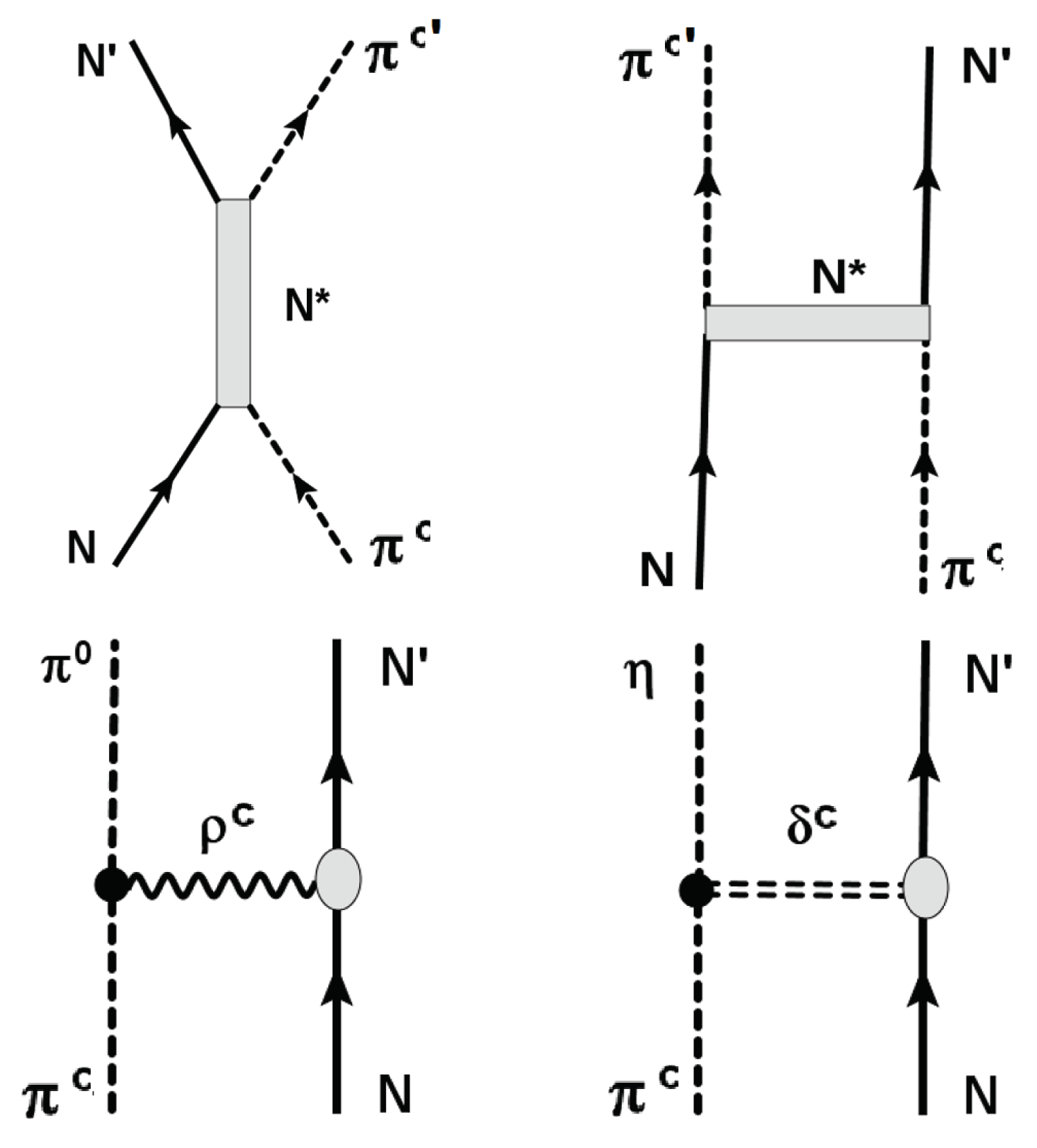
As depicted in Figure 3 pion–nucleon scattering is determined by the formation of N * resonances in the s–channel and t–channel meson exchange. Meson exchange will contribute to all pion–nucleon partial waves as an omnipresent, smooth background contribution. The formation of elastic resonances, however, is an interaction mode which depends critically on the partial wave. The most prominent example of a N * state is the Δ ( 1232 ) resonance at centroid energy M = 1232 MeV and a with Γ = 120 MeV. In spectroscopic notation, L 2 I 2 J ( M ) , with orbital angular momentum L = S , P , D in the π N –system, isospin I = 1 2 , 3 2 , and total angular momentum J = = 1 2 , 3 2 , 5 2 , the Delta resonance is denoted by P 33 ( 1232 ) , hence indicating a P-wave resonance with stretched isospin and spin-orbital coupling. The next higher resonance is the Roper resonance, P 11 ( 1440 ) . At higher energies up to about 2.5 GeV S–, D– and F–wave resonances have been confirmed as listed and regularly updated by the Particle Data Group [49]. Meson-nucleon spectroscopy is an intensively studied field. Among several other approaches the Giessen coupled channels model was used in the past successfully to describe photo–production of mesons on the nucleon and meson–nucleon dynamics, see e.g. [50] for an overview.
The diagrams of Figure 3 together with a few other graphs and appropriately chosen form factors, see e.g. [50], define the bare pion–nucleon π N interactions V π N . Since we are dealing with nuclear interactions of considerable strength and additional resonant enhancements, the scattering series must be summed to all orders. This is achieved by the Lippmann–Schwinger integral equation [28] for the T–matrix which in non–relativistic notation is:
T π N ( k , k ) = V π N ( k , k ) + d 3 q ( 2 π ) 3 V π N ( k , q ) G π N ( s | q ) T π N ( q , k ) ,
to be solved numerically as a set of coupled integral equations. The essence of the T–matrix formalism is to shift dynamics from wave functions to the interaction operator [28,29] such that T π N ( k , k ) is defined as the plane wave matrix element of the correlated pion–nucleon scattering operator. Thus, in matrix elements T π N ( k , k ) has always to be combined with the incoming and outgoing pion–nucleon plane waves e i k · x and e i k · x , respectively, where x = r N r π . It is worth mentioning, that the earlier pion–DCE studies tried to describe pion–nucleon interactions in the isovector channel in a perturbative approach, focussed on the Delta(1232)–resonance. Such a reductive approach is not supported by our results. An alternative approach utilizing an effective potential is presented in the next section.
For pionic SCE and DCE reactions the focus is on interactions of mesons with nucleons immersed in matter. As a result, N * N 1 particle–hole configurations are excited as depicted in Figure 4. In a different context such a scenario is discussed in detail in [51]. Since the N * particle state is unstable and finally decaying by strong interactions into N N 1 states under emission of a meson. In our case, the decay leads to an outgoing neutral or charged pion.
While pion–nucleon scattering trivially proceeds on the basis of definite partial of well defined orbital and total angular momentum, N * N 1 dynamics is determined by the full pion–nucleon scattering amplitude, summed over partial waves. Hence, the vertices of Figure 3 being active in π N scattering and the ones of Figure 4, describing π c N * N 1 π c , c , c = 0 , ± 1 , processes, are quite different as will be seen in the following.

6.2. Pion–Nucleon Potential Model for the Scattering Amplitudes

For the present purpose a full scale coupled channels calculation as in the Giessen model and comparable approaches is of little sense. Here we are not interesting in a detailed spectroscopic study of N * states and their excitation and decay by coupled meson–nucleon channels. Rather, our interest is specifically focused on the isovector pion–nucleon T–matrix as an effective t–channel pion- N N 1 interaction. A meaningful approach is to use an effective optical potential (OP) model where the self–energies from coupled channels dynamics are treated by complex dispersive optical potentials. Pion–nucleon potential models have been used before with surprising success in reproducing the spectral distributions, see e.g. [52,53]. We account for the opening of nucleon–multi–pion decay channels by partial wave dependent pion-nucleon optical potentials (OP). The imaginary parts are modelled according to the opening of nucleon–multi-meson decay channels which finally are the observable configurations. In our r–space approach, the best results were obtained by using Wood–Saxon form factors with very small diffusivities which are well approximated by step functions. The parameters were adjusted to the partial wave cross sections of full scale coupled channels (CC) calculations where the latter are fitted to the available meson–nucleon data.

7. Numerical Studies

7.1. Pion–Nucleon Partial Wave Cross Sections

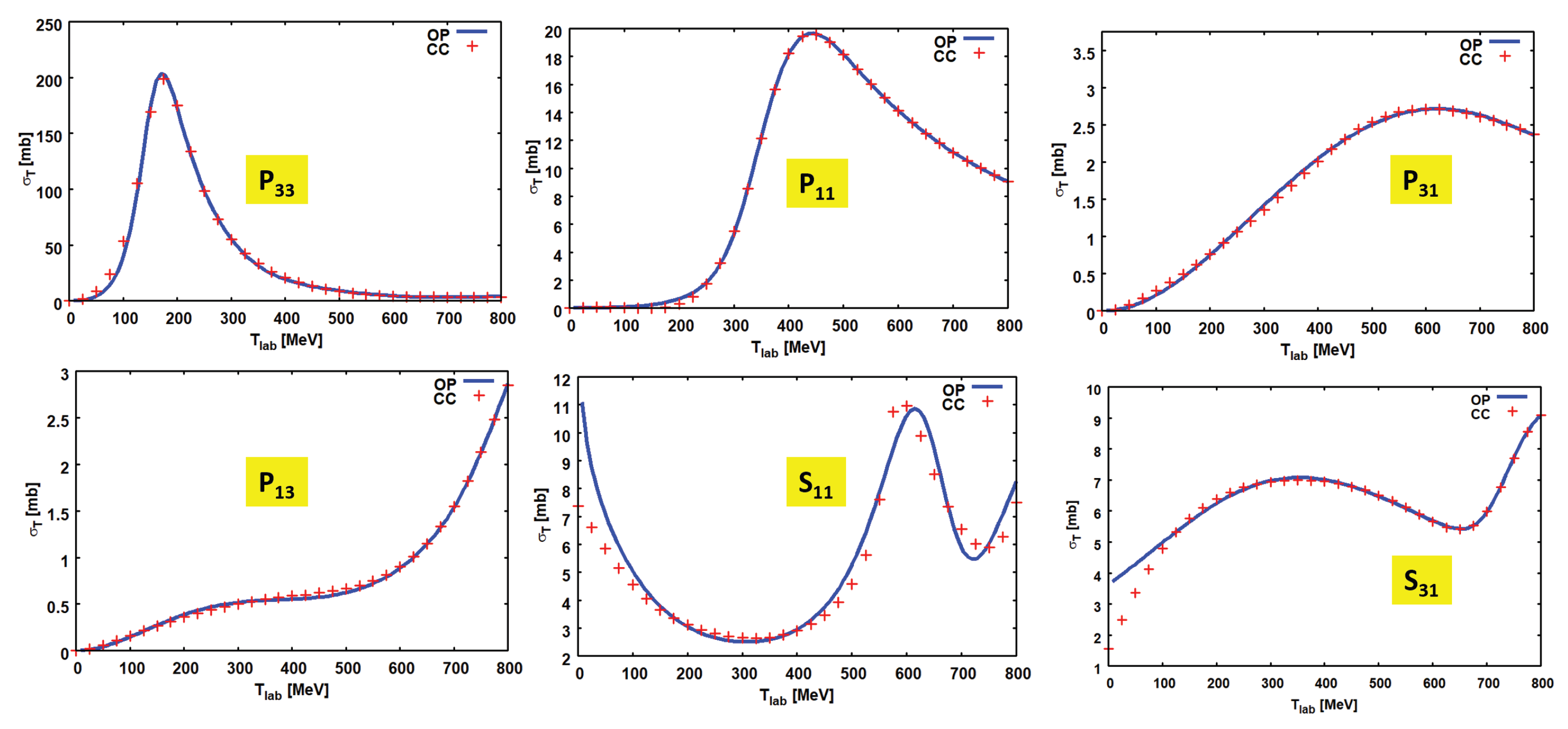
Representative results illustrating the quality of the description for P– and S–wave total cross sections are shown in Figure 5. The reference data from explicit coupled channels calculations are surprisingly well described, especially in view of the simplicity of a potential approach. In detail, the Delta and the Roper resonance are well reproduced as is the case for the I = 1 2 and I = 3 2 S–wave sector. In the S-wave spectra the highly disputed S 11 ( 1520 ) resonance is most prominently visible as a rather narrow structure on a non–resonant background. Interestingly, the S 11 ( 1520 ) peak is largely the result of interferences of a virtual s–channel state with the smooth t–channel background. A long tome ago, the same explanation was already obtained in coupled channels calculations [54] and more recent studies come to similar conclusions. The present potentials model results may be taken as an interesting independent confirmation of the earlier CC results. Overall, the agreement of the present results with the CC–generated reference data is surprisingly good in view of the extremely simplified model. Larger deviations occur in the S–wave spectra. Close to threshold, the S–wave cross sections show some deficiencies and deviations are seen in the S 31 channel also towards the highest considered energies. They are, however, of minor importance for the present use in MDCE studies because T π N is dominated by P–wave interactions.
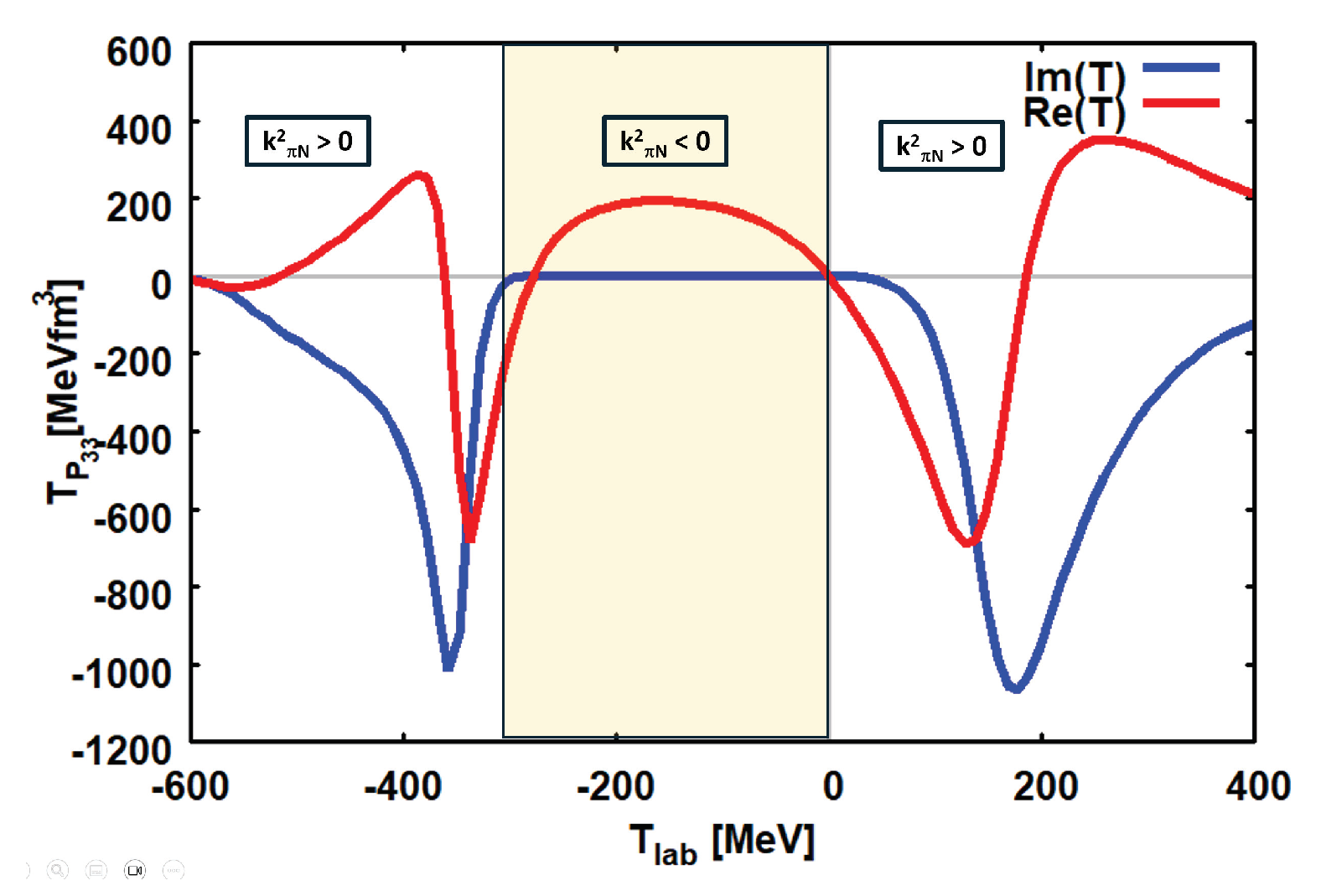
Partial wave total cross sections are defined by the imaginary parts of the scattering amplitudes, σ T L 2 I 2 J I m ( T L 2 I 2 J ) . Thus, a first important test of the reliability of the model calculations is to compare real and imaginary parts of scattering amplitudes. The agreement between OP and CC scattering amplitudes is very satisfying. An example is shown in Figure 6 where the P 33 and the S 31 partial waves scattering amplitudes are compared to the corresponding CC amplitudes.
The P–wave cross sections and scattering amplitudes are slightly better reproduced than the corresponding S–wave quantities. The CC calculations show that the S–wave components, which are generally located at higher energies, are strongly affected by coupled channel dynamics. Physically, an important source of CC effects are multi–meson decay channels, either by direct N * n π decay, possibly passing through intermediate heavy mesons, or sequentially by decay chains passing through lower lying resonances, e.g. N * Δ ( 1232 ) + π N + 2 π . Such details, of course, are not resolved in the present approach but are taken into account globally by the dispersive parts of the partial wave potentials.

7.2. Construction of the Pion-Nucleon T–matrix

In order to construct the pion–nucleon T–matrix, Eq.(9), we need to determine the three vertex form factors T 0 , 1 , 2 . That goal is achieved by considering the partial wave structure of the T–matrix and collecting terms of the proper multipolarity and dependencies on the nucleon spin. That task is well documented in the literature, e.g. [55] and reviewed briefly in Appendix D.
In the energy region of our interest, the vertex form factors are obtained with sufficient accuracy by the two S-wave amplitudes S 11 and S 31 and the three P–wave contributions, P 11 , P 31 , and P 33 , respectively. Within this basis, the form factors are
T 0 ( k π N ) = 1 3 F ( k π N ) U S 11 ( s π N ) U S 31 ( k γ )
T 1 ( k π N ) = 1 3 F ( k π N ) U P 11 ( k π N ) + 2 U P 13 ( k π N ) U P 31 ( k π N ) 2 U P 33 ( k π N )
T 2 ( k π N ) = 1 3 F ( k π N ) U P 13 ( k π N ) U P 11 ( k π N ) U P 33 ( k π N ) + U P 31 ( k π N )
where k π N = k π N ( s π N ) is the invariant pion–nucleon three–momentum.
The partial wave scattering amplitudes are normalized to units of 1/MeV. By means of the kinematical factor F ( k ) = 4 π / ( 2 m π N k ) the T–matrix amplitudes are normalized to units of 1/MeV   2 . m π N is the pion–nucleon reduced mass and k = k ( s π N ) denotes the invariant relative pion–nucleon momentum. For the numerical results, displayed below, we follow, however, the widely used practice to present the form factors as function of the pion kinetic energy in the laboratory frame, which is obtained by T l a b = ( s π N ) ( m π + M N ) 2 ) / ( 2 M N ) .
Although each of the (complex–valued) partial wave scattering amplitudes varies considerably with energy as seen in Figure 6, their superpositions are much smoother functions, as look to Figure 8 confirms. By multiplication with ( c ) 3 the units my be changed to MeVfm   3 which is a typical unit for volume integrals and momentum space form factors of NN–interactions.

7.3. Extrapolation into the Subthreshold Region

The most important advantage of the OP approach for MDCE theory, however, is to have at hand a method which allows to extrapolate reliably and easily into the subthreshold region. As illustrated in Figure 7 for the P 33 partial wave, three different sheets are covered kinematically. The sheets are distinguished by the values of the invariant relative pion–nucleon momentum k π :
  • In the physical region s π N > ( m π + m N ) 2 and the invariant momentum k π 2 > 0 and T L a b > 0 are positive.
  • In the interval ( m π m N ) 2 < s π N < ( m π + m N ) 2 one finds k π N 2 < 0 and T L a b < 0 .
  • If also s π N < ( m π m N ) 2 positive values of k π N 2 > 0 are recovered but T L a b < 0 remains negative.
In Figure 7 it is seen that the T–matrix changes is a characteristic manner: real and imaginary parts are non–vanishing in the physical region while in the first subthreshold sheet the imaginary parts vanish, but recovers as soon as the second subthreshold sheet is entered.
Because of the intrinsic momentum spread introduced by ISI and FSI, in a heavy ion MDCE reaction in principle all three kinematical sheets will be visited while propagating through the intermediate s–channel pion–nucleon systems. In other words, ISI and FSI lead effectively to a sampling over the distribution of MDCE box diagrams of different kinematical and dynamical content.
The vertex form factors T 0 , 1 , 2 are shown as functions of the pion energy in the laboratory system in Figure 8. When traversing the boundaries between the kinematical sheets the amplitudes develop cusps. In the T 0 amplitude, defined by the S–wave scattering amplitudes, the cusps are most pronounced, while they are washed out in the P–wave amplitudes T 1 , 2 . A closer inspection shows that the P–wave amplitudes are in magnitude about a factor of 1.5 to 2 larger than T 0 . That difference will be enhanced further in matrix elements by the fact that in T π N the P–wave terms scale by p 2 for SCE transitions and even by p 4 in DCE transitions. Thus, already from these considerations we expect a prevalence of the momentum–dependent P–wave terms in a DCE reaction.

7.4. Form Factors of the Pion Potentials

Since the pion–nucleon T–matrix, Eq.(9), consists of three terms, the pion potential U π , Eq.(38) or Eq.(40), respectively, is in general in either version a superposition of nine terms U i j ( x | p 1 , p 2 ) , i , j = 0 , 1 , 2 , which depend on the three–momenta p 1 and p 2 . Likewise, because of p 1 p 2 = q α β , we may choose one of the momenta and the three–momentum transfer q α β of the reaction and momentum variables.
A simplification is obtained for vanishing total momentum transfer | q α β | = 0 which implies collinearity of the momenta, p 1 | | p 2 and | p 1 | = | p 2 | = p . Then, the number of elements reduces to six independent scalar form factors, U i j ( x | p ) , i j = 0 , 1 , 2 . Under these conditions we find the diagonal potentials
U 00 ( x | p ) = U 0 2 ( k π N ) d 3 k ( 2 π ) 3 g γ ( + ) ( k | p 1 ) e i k · x
U 11 ( x | p ) = U 1 2 ( k π N ) p 2 3 m π 4 d 3 k ( 2 π ) 3 g γ ( + ) ( k | p 1 ) k 2 cos 2 ( θ ) e i k · x
U 22 ( x | p ) = U 2 2 ( k π N ) p 2 3 m π 4 d 3 k ( 2 π ) 3 g γ ( + ) ( k | p 1 ) k 2 sin 2 ( θ ) e i k · x
 
and three non-diagonal potentials
U 01 ( x | p ) = 2 U 0 2 ( k π N ) d 3 k ( 2 π ) 3 g γ ( + ) ( k | p 1 ) e i k · x
U 02 ( x | p ) = 2 U 1 2 ( k π N ) p 2 3 m π 2 d 3 k ( 2 π ) 3 g γ ( + ) ( k | p 1 ) k 2 cos 2 ( θ ) e i k · x
U 12 ( x | p ) = 2 U 2 2 ( k π N ) p 2 3 m π 4 d 3 k ( 2 π ) 3 g γ ( + ) ( k | p 1 ) k 2 sin ( θ ) cos ( θ ) e i k · x .
For simplicity, the potentials are evaluated numerically for the special case that x and p are collinear as well, and x | | p implies k · x = k x cos ( θ ) .
By expressing the sine– and cosine functions in terms of Legendre–polynomials or Legendre–functions, respectively, the angle integrations can be performed in closed form. The momentum integrals are regularized by dipole form factors with cut-off Λ = 1000 MeV/c. The resulting k–integrals, given by products of ordinary or spherical Bessel functions and Legendre functions of 2nd kind, all combined with powers of k, have to be evaluated numerically. The full propagator, Eq.(29), is used. Excitation energies, however, are neglected which is justified in view of the rather weak dependence on energies well below the pion rest mass..
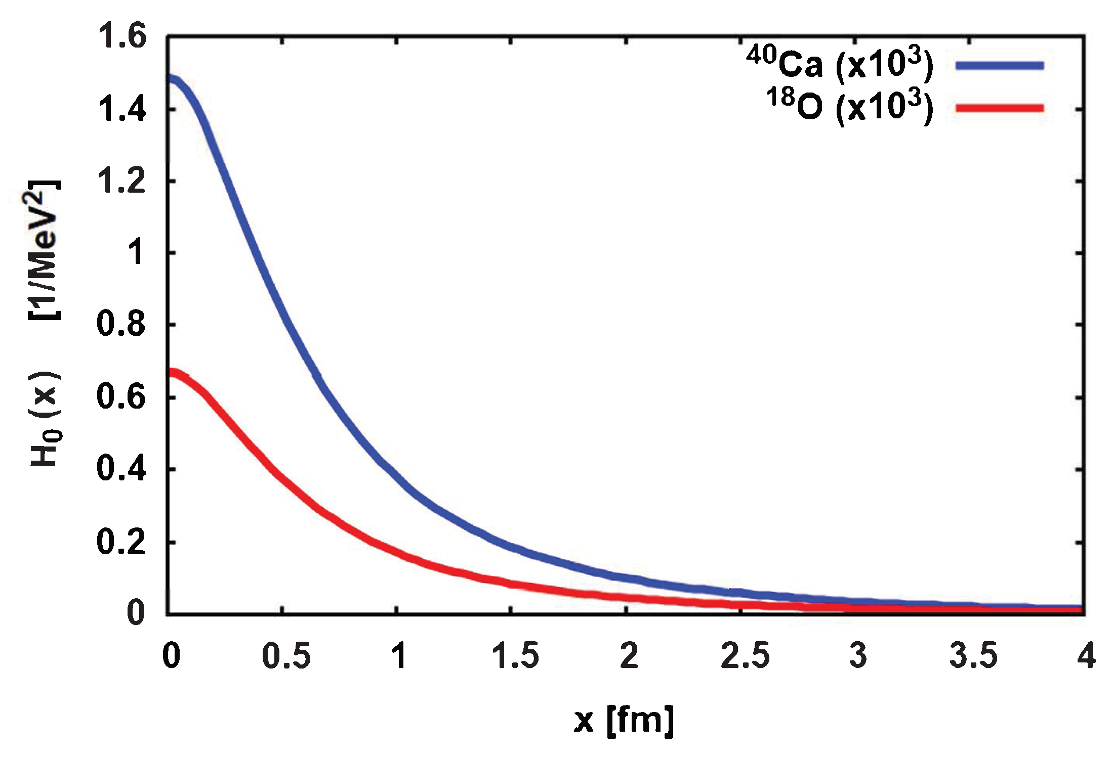
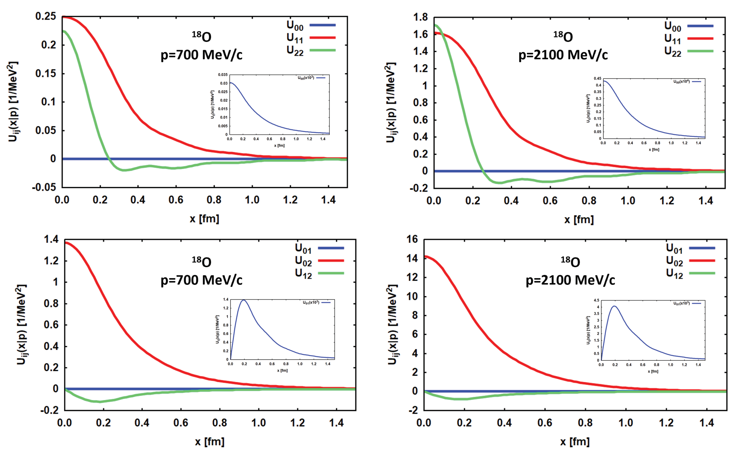
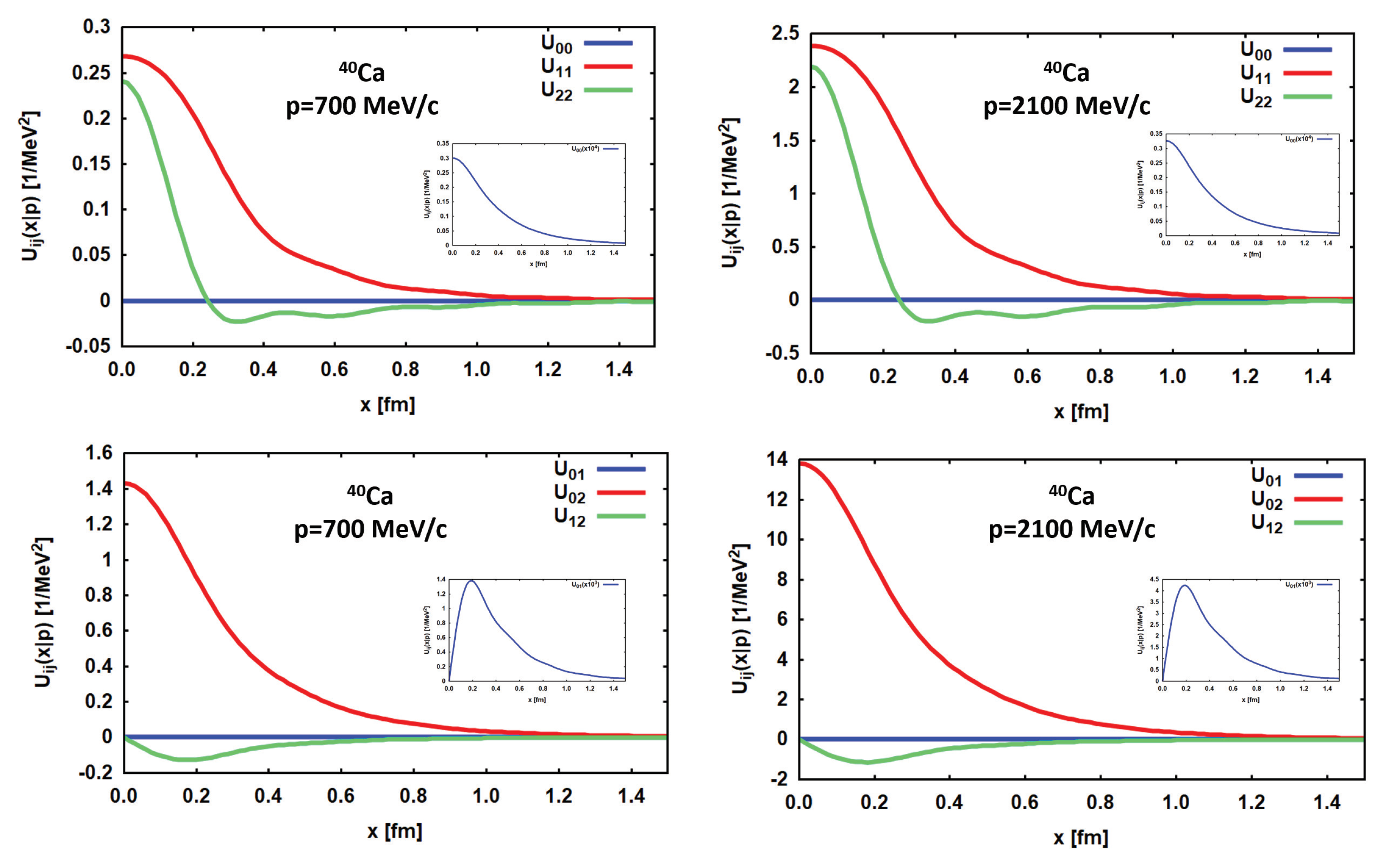
Typical results for the pion potentials U i j for the reaction   18 O+   40 Ca at T l a b = 270 MeV are shown in Figure 9 and in Figure 10, respectively. As discussed above, ISI and FSI favor momenta p 1 , 2 which are centered around the on–shell momenta of entrance and the exit channel, k α k β 2100 MeV/c. Accordingly, the potentials are displayed at p k α and p = 1 3 k α . In magnitude the potentials increase with momentum which seems to be especially pronounced for the P–wave parts T 1 , 2 , However, as a look to Eqs.(46) and Eqs.(50), respectively, reveals that the enhancement is largely paid to the explicit dependence of the P–wave potentials on powers of p. Compared to that dependence, the S-wave form factors U 00 remain on small to moderate magnitude. For p k α the enhancement effect decreases and the S–wave potentials become relatively more important. Comparing the Oxygen and Calcium potentials, one observes a rather mild dependence on the nuclear system, as is expected for a short range phenomenon.
The s–channel π 0 exchange establishes in fact a rather tight two–nucleon correlation. Overall, the range of the potentials rarely reaches 40% of the range of pion–exchange, r π 1 / m π 1.4 fm. Hence, the MDCE processes is of a pronounced short–ranged character. The correlated pair of SCE vertices acts as a virtual, polarized pion dipole source. Comparison the data of the DCE reaction induced by   18 O+   40 Ca at T l a b = 270 MeV are found elsewhere [23].

7.5. Transition Matrix Elements

In closure approximation and with the pion potential formalism the TME are obtained in the condensed form
W A B ( p 1 , p 2 ) = I 2 2 ( π ) i , j = 0 , 1 , 2 M A B ( i j ) ( p 1 , p 2 ) .
Thus, the transition A B is described by a sum of nine partial TME
M A B ( i j ) ( p 1 , p 2 ) = B | e i p 2 · r 2 W A B ( i j ) ( x | p 1 , p 2 ) e i p 1 · r 1 I 2 ± 2 ( N ) | A
which are determined by the transition potentials W A B ( i j ) . They are defined and studied in detail in Appendix E. There it is also shown that useful and successful approach is to express momentum and spin operators in the basis of spherical unit vectors. In that basis one finds that W A B ( i j ) are dyadic tensor forms. The x–dependence is given by Yukawa–type form factors of rather short range of less than half of the range of a (static) pion–exchange potential. Hence,using contact interactions might be a meaningful approximation which, however, will not be considered further here.
The two–body operator connecting in Eq.(54) the initial and final state is in fact separable into one–body operators. That property is evident for the plane wave factor, considering that x = r 1 r 2 , and also the potentials W A B ( i j ) are given by products of one–body operators. In practical calculations, the plane waves are expanded into partial waves in r 1 and r 2 and by the formalism introduced in Appendix E also the potentials can be treated accordingly. At the end, Eq. (54) reduces to a (finite) sum of a number of multipole components which are determined by the angular momentum and parity selection rules of the DCE transition A ( Z , N | J A π A ) B ( Z ± 2 , N 2 | J B π B ) .
With the bi–spherical harmonics
Y ( 1 2 ) m ( x ^ , y ^ ) = m 1 m 2 1 m 1 2 m 2 | m Y 1 m 1 ( x ^ ) Y 1 m 1 ( y ^ ) .
we find
M A B ( i j ) ( p 1 , p 2 ) = 1 2 , m ( ) + m Y ( 1 2 ) m ( p ^ 1 , p ^ 2 ) M ( 1 2 ) m ( i j ) ( p 1 , p 2 )
The multipole TME are given by rank–2 isotensor two–body multipole operators
M ( 1 2 ) m ( i j ) ( p 1 , p 2 ) = B | R 2 ( r 2 | p 2 ) R 2 ( r 1 | p 1 ) m W A B ( i j ) ( x | p 1 , p 2 ) I 2 ± 2 ( N ) | A .
For i , j = 0 , 1 the MDCE transition operators are of spin–scalar character and the matrix elements describe non–spinflip double-Fermi (FF) excitation. The FF modes are described by spin–scalar one-body operators which are given by Riccati–Bessel functions j ( x ) :
R m ( r | p ) = j ( p r ) i Y m ( r ^ ) .
For i = j = 2 spin–vector transition operators are encountered which give rise to double excitations of Gamow–Teller (GG) modes, which includes spin–vector transition of natural and unnatural parity. If i = 2 but j = 0 , 1 or i = 0 , 1 and j = 2 we encounter two–body operators of mixed spin–scalar/spin–vector structure, leading to mixed FG and GF excitation by combination of a Fermi and Gamow–Teller mode.
The GG and mixed FG/GF modes are described by spin–vector one–body operators. Their derivation and especially proper implementation into the theory requires a remarkable amount of angular momentum recoupling. The spin–vector formalism for DCE reactions was studied in detail in [1] and will not be considered further here. As was shown also in [1] the GG operators support total spin transfers S = 0 , 1 , 2 , to be combined with the total orbital angular momentum transfer L to total angular momentum transfer J = L + S . That leads to a rich spectrum of transitions, e.g. a DCE reaction with J π = 0 + may proceed by L = 0 , S = 0 and L = 2 , S = 2 partial contributions.

7.6. Transition Matrix Elements in Collinear Approximation

For arbitrary values of p 1 and p 2 the evaluation and the practical handling of the TME is theoretically and numerically a formidable task. The efforts, however, are substantially reduced for collinear external momenta, i.e. p 1 | | p 2 and also p 1 p 2 = q 12 and ( p 1 + p 2 ) / 2 = P 12 are collinear. Further simplifications are obtained by imposing in addition the stronger constraint p 1 = p 2 = p which implies | q 12 | = 0 and P 12 = p . Then, Eq.(54) simplifies to
M ˜ A B ( i j ) ( p ) = B | e i p · x W ˜ A B ( i j ) ( x | p ) I 2 ± 2 ( N ) | A = B | W ^ A B ( i j ) ( x | p ) I 2 ± 2 ( N ) | A
As an example, we consider the L = 0 , S = 0 component of A ( Z , N | 0 + ) B ( Z ± 2 , N 2 | 0 + ) double–Fermi transitions. Hence, only the spin–scalar S–wave ( i = j = 0 ), P–wave ( i = j = 1 ) and the mixed S–/P–wave parts, ( i = 0 , j = 1 ) and ( i = 1 , j = 0 ), are considered. In Appendix F the spin–scalar collinear transition potentials W ^ A B ( i j ) are derived and their multipole structure is investigated. For 0 + 0 + transitions the complexity of the potentials is reduced further. For that case, explicit expression are found also in Appendix F.
Following [56] we assume that the states in the DCE daughter nucleus B are obtained by acting with appropriate many–body operators on the ground state of the parent nucleus A:
| B ( Z ± 2 , N 2 ) , J B M B C 1 C 2 z C 1 C 2 J B M B Ω C 1 Ω C 2 J B M B | A ( Z , N ) , J A M A + ,
where higher order quasiparticle configurations may contribute but will not be reached in leading order by the DCE transition operators. The same set of operators and the underlying basis of single article wave functions are used to express the transition potentials in second quantization. In practice, nuclear ground state properties are described with Hartree–Fock-Bogolyubov (HFB) theory and Quasiparticle Random Phase Approximation (QRPA) is used for excited SCE-type states, see e.g. [2].
Without going further into the details of the nuclear structure approach, the essence of the approach is that the TME, Eq.(59), are given by nuclear transition form factors
ρ λ μ ( C ) ( p ) A | [ Ω C , R λ μ ( r | p ) ] | A ,
The TME are obtained by the scheme developed in Appendix F. As a recipe we have to replace in the expression derived in the appendix the operators R λ μ by the Fourier-Bessel form factors ρ λ μ ( C ) ( p ) and finally perform the momentum integrals.
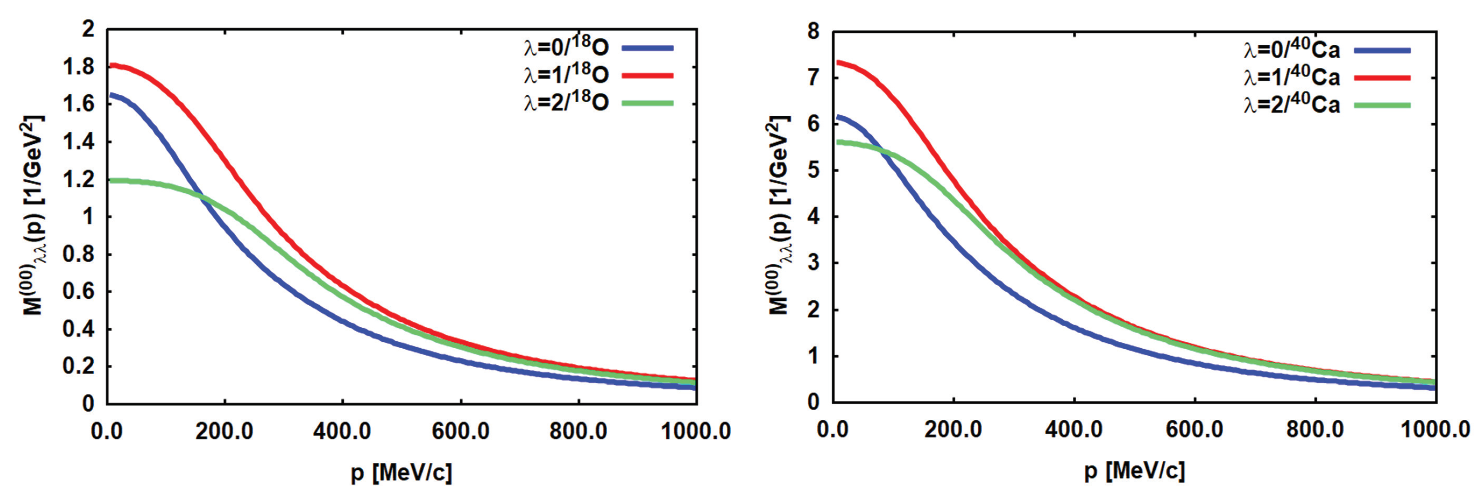
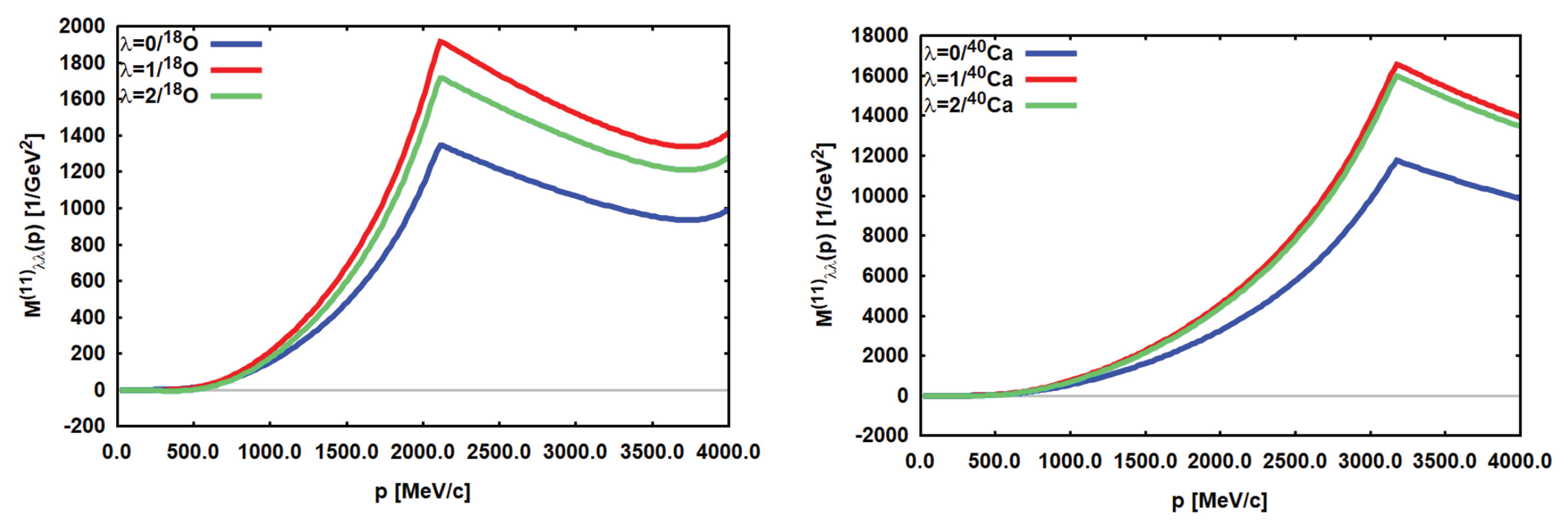
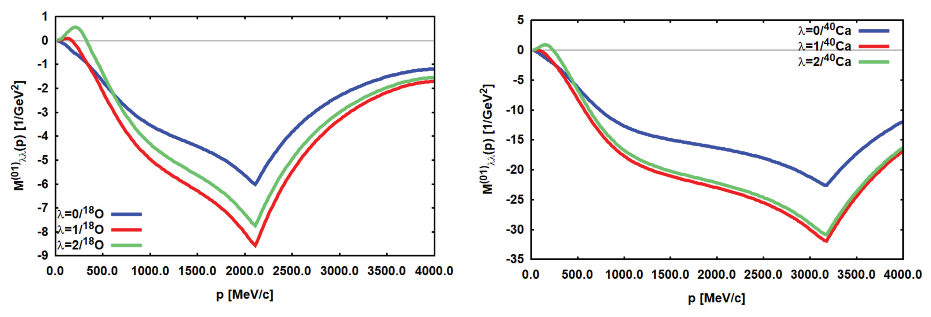
In Figure 11 to Figure 13 partial TME, Eq.(57), of 0 + 0 + transitions in   18 O   18 Ne and   40 Ca   40 Ar are shown. The TMEs are relevant for the DCE reaction   40 Ca ( 18 O , 18 Ne ) 40 Ar studied in [23,57]. State independent average transition densities are used which are averaged over the spectral distributions, normalized to the respective non–energy weighted multipole sum rule, corresponding to the unit strength form factors introduced in [56]. Hence, the results are representative for monopole FF modes in   18 Ne and in   40 Ar, relative to the respective parent nuclei.
Figure 11. DCE non–spinflip double–Fermi ( L = 0 ) transition matrix elements for   18 O 18 Ne (left) and   40 Ca 40 Ar (right), respectively, are shown in collinear approximation. The real parts of the double S–wave TME M ( λ λ ) L ( 00 ) for λ = 0 , 1 , 2 are compared. See text for further discussion.
Preprints 102517 g011
Figure 12. DCE non–spinflip double–Fermi ( L = 0 ) transition matrix elements for   18 O 18 Ne (left) and   40 Ca 40 Ar (right), respectively, are shown in collinear approximation. The real parts of the double P–wave TME M ( λ λ ) L ( 11 ) for λ = 0 , 1 , 2 are compared. See text for further discussion.
Preprints 102517 g012
Figure 13. DCE non–spinflip double–Fermi ( L = 0 ) transition matrix elements for   18 O 18 Ne (left) and   40 Ca 40 Ar (right), respectively, are shown in collinear approximation. The real parts of the mixed S/P–wave TME M ( λ λ ) L ( 01 ) for λ = 0 , 1 , 2 are compared. See text for further discussion.
Preprints 102517 g013
Comparing the results, the most outstanding feature are the differences between the S–wave and the P–wave TME. The double S–wave TME, Figure 11, contribute only at small momenta close to the threshold. The TME involving P–wave amplitudes, Figure 12 and Figure 13, increase strongly with momentum, exceeding the strength of the S–wave TME by large factors. The P–wave enhancement is largely an effect of the additional polynomial momentum dependencies up to order p 4 , see Appendix F. However, it has to be remembered that the shown results are the bare TME before ISI/FSI renormalization. After renormalization, i.e. in a full distorted wave calculation, especially the high momentum regions will be quenched in addition to the overall reduction by about 2 to 3 orders of magnitude, thus damping considerably the apparent enhancement.
For arbitrary total angular momentum J π various combinations of partial contributions of angular momentum J 1 π 1 and J 2 π 2 are allowed, constrained, however, by parity, π = π 1 π 2 , and otherwise limited only by the shell structure and related other properties of the nucleus under consideration. For the 0 + case, this means that in principle all pairs of transition densities of equal angular momentum 1 = 2 = λ may contribute. For the J = L = 0 case, this property of the TME is illustrated in the figures by showing the partial TME, Eq.(57), for λ = 0 , 1 , 2 . In magnitude and shape the partial TME are rather similar. Thus, we conclude that the MDCE operators supports a large spectrum of multipolarities, as typical for short range dynamics.
An eye–catching feature visible in all plots are the kinks. They appear at the momenta where the intermediate π + C channels crosses from below the on–shell boundary which produces a pole in the propagator. That happens at p 2156 MeV/c and p = 3225 MeV/c for π + 18 F and π + 40 K, respectively. Another feature is the crossing of the on–shell boundary of the π + N subsystems at the slightly smaller momenta p 2120 MeV/c for A=18 and p 3180 MeV/c for A=40. The location of these thresholds depends however, on the modelling of in–medium pion dynamics which here is not considered, as mentioned before. Above these momenta, the potentials develop imaginary parts of moderate strength which are not shown here.

8. Relation of Heavy Ion DCE Dynamics to Double Beta Decay

8.1. Leptonic and Hadronic DCE Processes

The past experiences with SCE reactions, see e.g. the review article [3] hints at a close relation between DSCE processes and 2 ν 2 β decay. Both are second order processes. Despite the large differences in dynamics, nuclear transitions are described by the same type of second order nuclear matrix elements given by the rank–2 polarization tensors derived in [56] and mentioned above. In Figure 14 the formal similarity of a DSCE reaction and two–neutrino DBD also on the underlying dynamical levels is elucidated by comparing two typical diagrams. The DBD process, see e.g. [21,22], is given by two half off–shell single beta decay (SBD) vertices where a highly virtual weak W gauge boson materializes into a lepton–antilepton pair. On the hadronic level, the corresponding DSCE process proceeds by a pair of SCE–type vertices where a highly virtual vector–isovector rho–meson decays into a pair of off–shell pions, ρ ± π 0 + π ± , where the neutral pions are rescattered and recombined within the same nucleus while the charged pions will be transmitted to the reaction partner and induce there DSCE transitions of complementary isospin character. In practice, however, the displayed elementary weak and the strong interaction diagrams together with other relevant graphs are taken into account globally by effective vertex form factors. In the weak sector, axial and vector coupling constants g A , V O ( 1 ) define the leading order contributions. For hadrons, the meson–nucleon isovector coupling constants, e.g the pion–nucleon coupling g π N O ( 10 ) , are playing the same role. In both cases, the vertices must be regularized by momentum–dependent form factors and, especially for hadrons, the scattering series have to summed to all orders which is achieved by solving a system of coupled Lippmann–Schwinger equations, see e.g. [24]. In other words, it will be very unlikely to measure selectively a single mechanism related to a specific Feynman diagram.
Also the similarities between MDBD and MDCE are understood the best by comparing typical interaction diagrams, Figure 15. The MDBD process is initiated again by an off–shell charged gauge boson, decaying, however, in a e ± and Majorana neutrinos ν M = ν ¯ M [21,22]. That equality is the defining aspect of MDBD because it is essential for keeping the pair of Majorana neutrinos captured by exchange between the two vertices. Thus, they induce a correlation between the two nucleons taking part in MDBD. Among the multitudes of processes of pion–nucleon interactions, ranging from point coupling and t–channel meson exchange to s–channel formation of π N resonances, see e.g. [50], in Figure 15 we show the one of diagrammatical form resembling closest the MDBD graph. The depicted (off–shell) rho–meson exchange process is closely related to the decay ρ ± π 0 + π ± . which on the mass–shell dominates the decay of a rho–meson. The displayed diagram corresponds can be understood as a rho–meson radiated off by the incoming pion there changing its charge and the rho–meson converts a neutron into a proton, hence creating a p n 1 configuration. The intermediate, again highly virtual, π 0 converts upon the nuclear background into ρ + + π resulting in a second p n 1 transition induced by the rho–meson and an outgoing π . Two remarks are in place: firstly, we emphasize that all processes occur far off their respective mass–shells; and secondly, the described rho–meson scenario is not an unique source for final [ p 2 n 2 ] B [ n 2 p 2 ] B projectile–target configurations but strongly competes with the resonance scenario by sequential N * n 1 p n 1 resonance formation–decay processes plus absorption and emission of the proper kind of pions.

8.2. Lepton MDCE in Heavy Ion DCE Reactions?

As an outlook to future work we point finally to possible purely leptonic contributions in a heavy ion MDCE reaction. Leaving aside the much weaker interactions of an electro–weak process,in principle the ions may also interact by the exchange of leptons. In Figure 16 as an example we show a diagram illustrating a DCE reaction by e ± t–channel exchange between the ions. By inverse beta–decay on a nucleon – without or with excitation of an N * resonance – the e ± are converted into a neutrino or antineutrino, respectively, which propagates in the s–channel, interacts with another nucleon and is converted into a lepton of a charge which is complementary to the one of the incoming lepton. As indicated in Figure 16 the ν / ν ¯ may be replaces by Majorana neutrinos ν M / ν ¯ M . Obviously, such processes are of special interest for MDCE and MDBD physics because they contains as a subprocess the same dynamical structure as neutrinoless DBD. The graph shows that this hitherto neglected MDCE process, relies completely on electro–weak interactions, probing directly the Majorana hypothesis in an off-shell process embedded into the environment of a heavy ion DCE reaction. It is also of interest that the diagram is of the same topology as the hadronic counterpart in Figure 2: The charged pions are replaced by electrons or positrons, respectively. The neutrinos and antineutrinos have taken over the role of the neutral pions and propagate between the two SCE vertices, thus also establishing a short range correlation. In the scenario involving Majorana neutrinos, the heavy ion DCE reaction corresponds to a double Majorana DBD process, occurring, however, off the mass shell. SCE scattering of leptons on nuclei is an important issue in understanding the interactions of high–energy cosmic neutrinos with matter. In that context SCE reactions induced by charged leptons and neutrinos are studied extensively in theory and experiment [58,59,60,61,62,63,64].
Hence, dynamically leptonic MDCE would include a process which depends on the same kind of interactions as expected for neutrinoless Majorana DBD (MDBD). Of special interest is that the vertices necessarily are determined by the same e ± ν M ν ¯ M conversion mechanisms as assumed for MDBD. In particular, lepton MDCE will probe in both of the interacting nuclei directly the Pontecorvo–Maki–Nakagawa–Sakata (PMNS) mass matrix [65,66,67], albeit under the conditions of a nuclear reaction.
As a caveat, the interactions involved in leptonic MDCE will be much weaker than hadronic MDCE. Nevertheless, it is tempting and worthwhile to investigate further that kind of heavy ion DCE sub–process, if not for heavy ion reactions but for DCE reaction with light ion or pion beams, respectively. The search for a signal might be tedious but looking for interference signals of the weak lepton MDCE amplitude with the dominating hadronic MDCE amplitude could be a promising approach. Since lepton MDCE is determined by long–range interactions, signatures will be observable most likely the best at extreme forward angles.

9. Summary

A generic feature of heavy ion DCE reactions is the versatility of reaction mechanisms by which the transition from the initial to the final channel can proceed. Occasionally, the related ambiguities are considered as a severe disadvantage of research with heavy ion beams. That point of view is much too pessimistic because in reality it is of advantage to be able to investigate all facets of a physical system under the same, well defined experimental conditions and describe the results consistently by the theoretical apparatus of nuclear many–body theory. The theoretical task and challenge is to overcome the traditional separation of nuclear reaction and nuclear structure physics. Heavy ion DCE physics demands a combined approach as indispensable for any research on quantum mechanical many–body systems. In the NUMEN project this decisive aspect is realized by the multi–method approach as discussed e.g. in [23].
In this work, we have investigated the theory of the Majorana (MDCE) mechanism which is an especially interesting part of heavy ion DCE reactions. As it was emphasized repeatedly, MDCE theory requires to go much beyond traditional concepts of nuclear reaction and structure theory. First of all, as a hitherto never considered aspect, the MDCE scenario relies on pion–nucleon dynamics which – from the beginning most likely unexpected – suddenly involves subnuclear degrees of freedom as nucleon resonances into a low–energy nuclear process. Already that aspect makes worth the efforts of investigating DCE reactions.
The MDCE process relies on a hitherto unknown mechanism, namely a dynamically induced rank–2 isotensor interaction. One of the central results was to introduce the MDCE closure approximation which allowed to derive pion potentials and two–body nuclear matrix elements connecting directly the entrance and the DCE exit channels. The pion potentials include combinations of spin and momentum scalar parts, spin–scalar longitudinal and spin–vector transversal momentum–vector components, all attached to a rank–2 isotensor operator. This rich operator structure allows wide–spread spectroscopic studies, allowing a detailed tomography of the nuclear wave functions. However, experimentally and theoretically such studies are highly demanding because they require to observe, analyse, and interpreted energy–momentum distributions over large ranges.
An especially appealing aspect of heavy ion DCE physics is the conceptional closeness to double beta decay research. That relationship was elucidated in some detail by considering the deeper levels underlying weak and strong DCE processes. They meet at the level of QCD and electro–weak physics. Clearly, neither DBD nor DCE reactions proceed at that those fundamental levels. Rather, both types of process are determined by low–energy realizations of the two fundamental theories of the current standard model of physics. However, the comparison of weak and strong DCE processes at the fundamental level is helpful to understand that nuclear DBD and nuclear DCE phenomena are finally nothing but two realizations of the same kind of fundamental processes. The differences in dynamics and strengths of DBD and hadronic DCE are due to the breaking of the fundamental symmetries in our physical low–energy environment.
As an interesting outlook to future work, the closeness of low–energy DBD and DCE physics was elucidated further by pointing to another competing reaction mechanism in heavy ion DCE reactions. Nothing forbids that MDCE reactions may proceed by the exchange of leptons. Leptonic MDCE proceeds by electro-weak dynamics but relies on diagrams of the same topology as investigated in this paper in detail for hadronic MDCE. It is left for future work to understand the dynamics and physics of lepton MDCE in detail and explore the competition of the two seemingly very different, but interfering types of weak and strong MDCE reaction mechanisms.
As a closing remark we emphasize again that in MDCE reactions are not governed by NN interactions as is the case for DSCE reactions. MDCE reactions are determined by pion–nucleon interactions which provide the required isospin operator structures for an effective rank–2 isotensor interaction. In MDCE reactions the colliding ions generate dynamically their own and specific isotensor interactions. Charge and baryon number conservation and isospin symmetry require that a Δ Z = + 2 transition in one nucleus must be accompanied by a Δ Z = 2 transition in the other nucleus. Obviously, all of the involved transitions are allowed and possible by strong nuclear interactions. Hence, hadronic DCE is not suppressed or even forbidden by violating fundamental laws of the standard model as required for 0 ν 2 β decay. While MDBD is constrained trivially to appear on the mass shell, MDCE reactions take advantage of the presence of another nucleus which gives access to a broad spectrum of off–shell processes and new research opportunities. Hence, it depends on our theoretical and experimental skills to identify and prepare the proper conditions under which rare hadronic or even leptonic MDCE events will become observable.

Acknowledgments

This work was supported financially in part by DFG, grant Le439/16-2 and INFN, LNS Catania.

Appendix A. Momentum Structure of Distorted Waves and Distortion Amplitudes

With ISI and FSI, the momentum relation are changed because the diffractive and absorptive interactions of the optical potential U o p t admix a certain amount of off–shellness into the theory, a seen immediately by expressing the distorted waves by their integral equation, e.g.
| χ k ( + ) = | ϕ k + d 3 k ( 2 π ) 3 | ϕ k 1 E k E k + i η ϕ k | U o p t | χ k ( + )
= | ϕ k + d 3 k ( 2 π ) 3 | ϕ k 1 E k E k + i η ϕ k | U o p t | ϕ k .
ϕ k and ϕ k are plane waves and E k , k are the kinetic energies defined by the momenta k , k , E k k 2 . Thus, a finite range optical potential will always lead to a wave functions with a momentum distribution centered at the physical asymptotic momentum k but with a finite width which in leading order is determined by the 3D-Fourier transform of the potential.
As anticipated in Section 3 the distorted wave may indeed by cast into the form
χ k ( + ) ( r ) = r | χ k ( + ) = e i k · r 1 h k ( r )
and referring to Eq.(A1) we derive
h k ( r ) = e i k · r d 3 k ( 2 π ) 3 e i k · r 1 E k E k + i η ϕ k | U o p t | χ k ( + )
where we changed to the coordinate representation r | ϕ k = e i k · r .
Now we are at the position for gaining further insight into the meaning and physical content of the distortion coefficients:
D ( p , k ) = 1 ( 2 π ) 3 ϕ p | χ k ( + ) = δ ( k p ) + 1 E k E p + i η 1 ( 2 π ) 3 ϕ p | U o p t | χ k ( + )
δ ( k p ) i π δ ( E k E p ) U o p t ( p , k ) | p | = | k | + P E k E p U o p t ( p , k )
where we have introduced U o p t ( k , k ) = 1 ( 2 π ) 3 ϕ k | U o p t | ϕ k and the Cauchy decomposition of the energy denominator was used. The distortion amplitudes defined in Eq.(15) are identified as the Fourier transform
f ( p , k ) = d 3 r ( 2 π ) 3 e i ( p k ) · r h k ( r )
= 1 E k E p + i η 1 ( 2 π ) 3 ϕ p | U o p t | χ k ( + ) .
Finally, we note that on the momentum shell | p | = | k | , defined by the pole part of the energy denominator, we retrieve the optical model elastic scattering amplitude, T o p t ( k , k ) ϕ k | U o p t | χ k ( + ) where k · k = k 2 cos θ .

Appendix B. Evaluation of the MDCE Box Diagram without ISI and FSI: Plane Waves

The total available energy in the rest frame of the incident A + A system is defined by the sum P α = k A + k A of the four–momenta k A , A of the incoming ions, leading to the Lorentz–invariant Mandelstam energy s α = P α 2 ( k A + k A ) 2 and by energy–momentum conservation s α = P β 2 = ( k B + k B ) 2 . In the laboratory frame with a beam of ions with rest mass M A impinging with kinetic energy T l a b on the target nuclei with rest mass M A the invariant energy is defined by s α = ( T l a b + M A + M A ) 2 T l a b ( T l a b + 2 M A ) . In the rest frame the ions carry the four–momenta k A , A = ( E A , A T , k α ) T with the invariant relative three–momentum and energies
k α 2 = 1 4 s α     ( s α ( M A + M A ) 2 ) ( s α ( M A M A ) 2 ) ; E A , A = M A , A 2 + k α 2 .
The outgoing ions B , B leave the interaction zone with four–momenta k B , B = ( E B , B , ± k β ) T . In the rest frame they are given by
k β 2 = 1 4 s α     ( s α ( M B + M B ) 2 ) ( s α ( M B M B ) 2 ) ; E B , B = M B , B 2 + k β 2 .
The reaction proceeds by momentum transfers in the t–channel q α β = k A k B = ( k A k B ) and in the u–channel p α β = k A k B = ( k A k B ) , leading to the well known invariants t = q α β 2 and u = p α β 2 . Together with the invariant total energy we retrieve the well known Mandelstam relation
s + t + u = M A 2 + M A 2 + M B 2 + M B 2
The charged pions are exchanged in the t–channel with momenta
p 1 = k 1 k A = k 2 + k A ; p 2 = k 1 k B = k 2 + k B .
Hence, we find
p 2 p 1 = k A k B = k B k A = q α β ; k 1 k 2 = k A + k A = k B + k B = P α ,
and the t–channel and s–channel momenta are related by
k 1 + k 2 ( p 1 + p 2 ) = p α β .
Summing the squares of these relation, the Mandelstam relation, Eq.(A11), is recovered but now expressed by the internal momenta of the box diagram. Since the four internal momenta of the box diagram are constrained by three invariants, we realize that the initially four independent momentum integrals have collapsed to a single momentum integration. A meaningful choice is to use one of the t–channel momenta as the independent variable, e.g. p 1 .
Considering the reaction in the ion–ion rest frame, in the plane wave (PW) limit the momenta are fixed by Eq.(22), from which we find immediately:
  • k A = ( E A ( k α ) , k α ) T and k B = ( E B ( k β ) , + k β ) T ,
  • k A = ( E A ( k α ) , + k α ) T and k B = ( E B ( k β ) , k β ) T ,
  • p 1 = ( 0 , p 1 ) T ia purely space–like four–momentum,
  • p 2 = ( E A E B , p 2 ) T includes formally the Q-value of the DCE reaction,
  • p 1 = k α and p 2 = k β are fixed by the three–momenta of the incoming and outgoing systems,
  • k 1 = p 1 + k A = ( E A ( k α ) , 0 ) T is a purely time–like four–vector,
  • k 2 = p 1 k A = ( E A ( k α ) , 0 ) T is a purely time–like four–vector.
Thus, in the PW limit the intermediate s–channels have available the energies k 1 2 = E A 2 = M A 2 + k α 2 and k 2 2 = E A 2 = M A 2 + k α 2 , showing that in the PW limit all momenta are known.
Dynamically, the intranuclear DCE transitions are given by sequential pion–nucleon SCE reactions, meaning that finally we have to resolve the intermediate configurations into their pion–nucleon substructures. The frost step is to recognize that the invariant energy available for the π 0 + C configurations is defined by the purely time–like four–vector k 1 . Thus, energetically s π C = k 1 2 = E A 2 = k α 2 + M A 2 defines the on–shell conditions. In their rest frame the pion and the SCE–excited nucleus C are moving with the invariant three–momentum k γ 2 = ( s π C ( M C * + m π ) 2 ) ( s π C ( M C * m π ) 2 ) / ( 4 s π C ) . Their four–momenta are k C = ( E c ( k γ ) , k γ ) T and k π = ( E π ( k γ ) , k γ ) T and k C + k π = k 1 . On the pion–nucleon level, we have available in the average the energy s π N = k 2 1 / A 2 = E A 2 / A 2 from which obtain as before the relative pion–nucleon momentum k , k 2 = ( s π N ( m N + m π ) 2 ) ( s π N ( m N m π ) 2 ) / ( 4 s π N ) . As a side result we find the equivalent (fictitious) pion energy in the laboratory frame,
T l a b = 1 2 m N s π N ( m N + m π ) 2 .
which attains positive values as long as s π N > ( m N + m π ) 2 ) . However, depending on the energy of the initial A + A –system, we may encounter s π N < ( m N + m π ) 2 and consequently T l a b < 0 , thus entering into the sub–threshold region. Classically, that energy region is of course forbidden, but not in quantum mechanics which, however, also inhibits to explore experimentally the below–threshold regions. The pion–nucleon interactions become virtual processes, governed by T π N which is located outside of the physically accessible region. Hence, it is the task of theory to provide a description which allows to extend T π N from the experimentally accessible regime into the sub–threshold energy regions encountered for pion–nucleon interactions in nuclear reaction like a heavy ion DCE reaction.
Obviously, there is no unique choice for (virtual) pion–nucleon kinematics under the conditions of a heavy ion reaction. The DCE reaction in total is a highly dynamical process and as such corresponds to sampling over many different π 0 + C configurations. The mean energy approach sketched above takes that in to account in the average.

Appendix C. Evaluation of the MDCE Box Diagram with ISI and FSI: Distorted Waves

A realistic description of heavy ion DCE reactions requires of course to include elastic ion–ion interactions. With ISI/FSI the interacting ions occupy regions of the configuration space beyond the on–shell point. In the ion–ion rest frame the off–shellness is defined by the distribution of the three–momenta p 1 , 2 around the respective on–shell momenta k α , β . The width and shape in general of the distribution is controlled by the distortion amplitudes f α , β . According to Appendix A, Eq.(A7), for a known optical potential, modelling the elastic ion–ion self–energies, the distributions are unambiguously known as determined by the half off–shell elastic scattering amplitudes of the incoming and outgoing ions.
Hence, ISI and FSI dissolve the strict momentum relations of the PW limit. This process, however, is of a purely virtual character which introduces a dynamically generated uncertainty in the three–momenta but does not alter the conserved energy. Hence, in the ion–ion rest frame, A and A carry momenta k A , A = ( E A , A ( p 1 ) , p 1 ) T while the on–shell energies k A , A 2 = M A , A 2 are retained. Accordingly, the exit channel is described by k B , B = ( E B , B ( p 2 ) , ± p 2 ) T , k B , B 2 = M B , B 2 .
As a result, also the intermediate pion–nucleus, and consequently the pion–nucleon, channels are affected because k 1 , 2 = ( E A , A ( p 1 ) , 0 ) T depend on the virtual momentum p 1 . Thus, s π C and s π N depend on p 1 . Since the MDCE reaction amplitude, Eq. (10), is given finally by integrations over the virtual momenta p 1 , 2 , the reaction A + A B + B proceeds as a sampling over a distribution of off–shell nuclear transition form factors, The distribution, however, is centered at the on–shell form factor which is directly related to the MDCE nuclear matrix element.

Appendix D. The Pion-Nucleon T–Matrix

The form factors T k , k = 0 , 1 , 2 , of the pion-nucleon T–matrix, Eq.(9), are given by the partial wave amplitudes. The The T 0 component is given by formation of π N S–wave N * resonances S 2 I 2 J of negative parity with isospin I = 1 2 , 3 2 and total angular momentum J π = 1 2 . The form factors T 1 , 2 of the longitudinal and transversal parts originate from P 2 I 2 J configurations of positive parity with isospin as before but J π = 1 2 + , 3 2 + . The most prominent P–wave resonances are the Delta and the Roper resonances with spectroscopic notations P 33 ( 1232 ) and P 11 ( 1440 ) , respectively.
At the energies considered here, MDCE reactions take place off the pion-nucleon mass shell. Hence, pion-nucleon scattering must be described by methods allowing to extrapolate T π N into off–shell energy regions. That goal is achieved by appropriately modelling the pion self–energies with analytically given complex–valued form factors where parameters are adjusted to on–shell observables which in our case are partial wave cross sections. In order to obtain converged below–threshold results, in practical calculations resonances up to the mass region of about 2 GeV must be taken into account.
The vertex form factors of the isovector pion–nucleon T–matrix are obtained from the scattering amplitudes U L 2 I 2 J in the various pion–nucleon channels by proper isospin coupling. The pion–nucleon scattering amplitudes are measured (and calculated) in the particle basis [ π ± n ] , [ π ± p ] , [ π 0 n ] , and [ π 0 p ] , respectively. The pion–nucleon states are transformed to the isospin basis by Clebsch–Gordan coefficients.For example,
| π p = T , T 3 ( 1 1 1 2 1 2 | T T 3 ) | T T 3
where T = 1 2 , 3 2 and in above case we have T 3 = 1 2 . The scattering amplitudes in the particle basis are set equal to the matrix elements which are obtained in the isospin basis for the isoscalar and the isovector interactions. The pion–nucleon T–matrix T ^ = T 0 + T 1 T π · τ is an isospin invariant operator and as also are the matrix elements. The isoscalar and isovector operator form of the T–matrix is finally obtained by inversion from the scattering amplitudes in the particle basis. The procedure is discussed e.g. in [55]. The result is
T 0 ( k ) = 1 3 F ( k ) U S 11 ( k ) U S 31 ( k )
T 1 ( k ) = 1 3 F ( k ) U P 11 ( k ) + 2 U P 13 ( k ) U P 31 ( k ) 2 U P 33 ( k )
T 2 ( k ) = 1 3 F ( k ) U P 13 ( k ) U P 11 ( k ) U P 33 ( k ) + U P 31 ( k )
The factors of ± 1 3 and ± 2 3 are resulting from the isospin Clebsch–Gordan coefficients.
The scattering amplitudes are normalized to units of 1 / M e V . With the the kinematical factor F ( k ) = 4 π 3 / ( 2 m π N ) the T–matrix amplitudes are normalized to units of MeVfm   3 . m π N is the pion–nucleon reduced mass. k = k ( s π N denotes the invariant relative pion–nucleon momentum which is determined by the invariant Mandelstam energy s π N .

Appendix E. Nuclear Matrix Elements and Pion Potentials

In closure approximation, the TME are given in general by a superposition of nine terms
W A B ( p 1 , p 2 ) = i , j = 0 , 1 , 2 I 2 2 ( π ) B | e i p 2 · r 3 W A B ( i j ) ( x | p 1 , p 2 ) e i p 1 · r 1 I 2 ± 2 ( N ) ( 13 ) | A
I 2 ± 2 ( N ) ( 13 ) = τ 3 τ 1 2 ± 2 is the nucleon rank–2 isotensor operator and I 2 ± 2 ( π ) denotes the pion counter apart. The distance between the two SCE–vertices, i.e. the distance between the participating nucleons, is x = r 1 r 3 .
The three diagonal potentials are
W A B ( 00 ) ( x | p 1 , p 2 ) = U 00 ( x ) ,
W A B ( 11 ) ( x | p 1 , p 2 ) = U 11 ( x | p 1 , p 2 ) ,
W A B ( 22 ) ( x | p 1 , p 2 ) = σ 3 · U 22 ( x | p 1 , p 2 ) · σ 1 .
As seen below, U 00 and U 11 , respectively, are scalar forms giving rise to spin–scalar double excitations of Fermi–character (FF). U 22 is a dyadic vector form featuring spin–vector double excitations of Gamow–Teller type (GG).
The two non–diagonal terms inducing FF–modes are
W A B ( 01 ) ( x | p 1 , p 2 ) = U 01 ( x | p 1 ) ,
W A B ( 10 ) ( x | p 1 , p 2 ) = U 10 ( x | p 2 ) .
The remaining four non–diagonal terms are of mixed spin character inducing FG– and GF–modes, respectively:
W A B ( 02 ) ( x | p 1 , p 2 ) = U 02 ( x | p 1 ) · σ 1 ,
W A B ( 20 ) ( x | p 1 , p 2 ) = σ 3 · U 20 ( x | p 2 ) ,
W A B ( 12 ) ( x | p 1 , p 2 ) = U 12 ( x | p 1 , p 2 ) · σ 1 ,
W A B ( 21 ) ( x | p 1 , p 2 ) = σ 3 · U 21 ( x | p 1 , p 2 ) .

Appendix E.1. The S–wave Potential

The diagonal S–wave potential is easily evaluated:
U 00 ( x ) = T 0 ( k π N ) d 3 k ( 2 π ) 3 g γ ( + ) ( k | p 1 ) e i k · x T 0 ( k π N ) = H 0 ( x )
with the scalar monopole form factor
H 0 ( x ) = T 0 2 ( k π N ) 1 2 π 2 0 d k k 2 g γ ( + ) ( k | p 1 ) j 0 ( k x ) ,
where j ( k x ) is Riccati–Bessel function of order . Numerically, the form factor resembles a regularized Yukawa potential, as seen in Figure A1. The magnitude of H 0 is defined s γ , γ = E A , A 2 ( p 1 ) , see Eq.(29).
Figure A1. The S–wave form factor H 0 ( x ) for   40 Ca (blue) and   18 O (red). The full propagator, Eq.(29), was used. See text for further discussion.
Preprints 102517 g0a1

Appendix E.2. The Diagonal P–wave and the Mixed S–/P–wave Potentials

The mixed S–/P–wave potentials and the diagonal P–wave potentials are evaluated by expressing the momentum vectors in spherical coordinates, see e.g. [1]. The spherical basis is defined by the bi–orthogonal set of unit vectors { e m , e m * } , m = 0 , ± 1 :
e ± 1 = ± 2 e x ± i e y ; e 0 = e z
e m * · e n = e m · e n * = δ m n .
The vector products are
e i × e j = ϵ i j k e k
where the Levi–Civita tensor is evaluated with { 1 , 0 , + 1 } = { 123 } . In that basis, space–like three-vectors V are given by:
V = m = 0 , ± 1 e m V m * = m = 0 , ± 1 V m e m * .
where
V m = V · e m ; V m * = e m * · V
A particular useful result is that the spherical components of V can be expressed in terms of spherical harmonics
V m = V 4 π 3 Y 1 m ( V ^ ) ,
where V = | V | and the rank–1 spherical harmonics Y 1 m ( V ^ ) = Y 1 m ( θ V , φ V ) , m = 0 ± 1 , describes the orientation of V in 3D–space.
In the mixed S–/P–wave potentials and in the diagonal P–wave potentials we encounter monadic and dyadic structures of tensorial rank 1 and rank 2, respectively:
H ( x ) = d 3 k ( 2 π ) 3 g γ ( + ) ( k | p 1 ) e i k · x k .
H ( x ) = d 3 k ( 2 π ) 3 k g γ ( + ) ( k | p 1 ) e i k · x .
H ( x ) = d 3 k ( 2 π ) 3 k g γ ( + ) ( k | p 1 ) e i k · x k .
In the spherical basis, the tensors become
H ( x ) = m = 0 , ± 1 H 1 m ( 01 ) ( x ) e m * ,
H ( x ) = m = 0 , ± 1 e m ( ) 1 + m H 1 m ( 10 ) ( x ) .
The rank–2 tensor is treated accordingly but leads to a more involved structure:
H ( x ) = λ = 0 , 2 ; μ ( ) λ + μ H λ μ ( 11 ) ( x ) e e λ μ
with the dyadic products
e e λ μ = m , n = 0 , ± 1 1 m 1 n | λ μ e m e n .
The multipole form factors are
H λ μ ( 1 2 ) ( x ) = H λ ( 1 2 ) ( x ) i λ Y λ μ ( x ^ )
with the radial form factor
H λ ( 1 2 ) ( x ) = C λ ( 1 2 ) 1 2 π 2 0 d k k 2 + 1 + 2 g γ ( + ) ( k | p 1 ) j λ ( k x ) .
The parity coefficient
C λ ( 1 2 ) = 4 π 3 1 + 2 2 ( 2 1 + 1 ) ( 2 2 + 1 ) 4 π ( 2 λ + 1 ) 1 0 2 0 | λ 0 1 2 1 + ( ) 1 + 2 + λ
vanishes if 1 + 2 + λ is an odd number. A collection of Clebsch–Gordan coefficients is found in Tab.Table A1. Other values of relevance for the present purpose are obtained readily by means of the symmetry relations
1 , m 1 , 2 , m 2 | λ , μ = ( ) 1 + 2 λ 1 , m 1 , 2 , m 2 | λ , μ
and also
2 , m 2 , 1 , m 1 | λ , μ = ( ) 1 + 2 λ 1 , m 1 , 2 , m 2 | λ , μ .
Table A1. Short table of Clebsch-Gordon coefficients.
1 , m 1 2 , m 2 λ , μ 1 m 1 2 m 2 | λ μ
0,0 0,0 0,0 1
1,0 1,0 0,0 1 3
1,1 1,-1 0,0 1 3
1,0 1,0 2,0 2 3
1,1 1,-1 1,0 1 2
1,1 1,-1 2,0 1 6
1,1 1,0 2,1 1 2
1,1 1,1 2,2 1
The diagonal P–wave transition potentials are given by:
U 11 ( x | p 1 , p 2 ) = 1 m π 4 T 1 ( k π N ) p 2 · H ( x ) · p 1 T 1 ( k π N ) ,
and
U 22 ( x | p 1 , p 2 ) = 1 m π 4 T 2 ( k π N ) σ 3 · p 2 × H ( x ) × p 1 · σ 1 T 2 ( k π N ) .
The mixed S–/P–wave transition potentials are
U 01 ( x | p 1 ) = 1 m π 2 T 0 ( k π N ) H ( x ) · p 1 T 1 ( k π N ) ,
U 10 ( x | p 2 ) = 1 m π 2 T 1 ( k π N ) p 2 · H ( x ) T 0 ( k π N ) ,
U 02 ( x | p 1 ) = 1 m π 2 T 0 ( k π N ) H ( x ) × p 1 · σ 1 T 2 ( k π N ) ,
U 20 ( x | p 1 ) = 1 m π 2 T 2 ( k π N ) σ 3 · p 2 × H ( x ) · p 1 T 0 ( k π N ) ,
U 12 ( x | p 1 , p 2 ) = 1 m π 4 T 1 ( k π N ) p 2 · H ( x ) × p 1 · σ 1 T 2 ( k π N ) ,
U 21 ( x | p 1 , p 2 ) = 1 m π 4 T 2 ( k π N ) σ 3 · p 2 × H ( x ) · p 1 T 1 ( k π N ) .

Appendix F. Spin–Scalar Transition Potentials in Collinear Approximation

In the collinear limit it is mathematically of advantage to include the plane wave factors into the potentials. The modified spin–scalar transition potentials were introduced in Eq.(59). They are given by
W ^ A B ( i j ) ( x | p , p ) = e i p · x W ˜ A B ( i j ) ( x | p , p ) = i = 0 , 1 , j i W i j ( r 1 , r 2 | p ) ,
where x = r 1 r 2 . By a proper change of integration variables k q = k + p we find the transition potentials
W i j ( x | p ) = T i ( k π N ) d 3 q ( 2 π ) 3 G i j ( q , p ) e i q · x T j ( k π N ) ,
with the integration kernels
G 00 ( q , p ) = g γ ( + ) ( | q p | )
G 01 ( q , p ) = 1 m π 2 p · ( q p ) g γ ( + ) ( | q p | )
G 11 ( q , p ) = 1 m π 4 p · ( q p ) 2 g γ ( + ) ( | q p | ) .
We define t = cos ϑ p q , express powers of t by sums of Legendre polynomials P ( t ) , use the addition theorem of spherical harmonics, and find
p · ( q p ) = p q t p 2 = p q P 1 ( t ) p 2 P 0 ( t )
= 4 π p q m Y 1 m * ( p ^ ) Y 1 m ( q ^ ) p 2 Y 00 * ( p ^ ) Y 00 ( q ^ )
The two–body potential obtained from the double P–wave amplitude contains the polynomial
p · ( q p ) 2 = p 2 q 2 t 2 + p 4 2 p 3 q t = 2 3 p 2 q 2 P 2 ( t ) 2 p 3 q P 1 ( t ) + ( 1 3 p 2 q 2 + p 4 ) P 0 ( t )
which is converted to
p · ( q p ) 2 = 4 π × 2 3 p 2 q 2 m Y 2 m * ( p ^ ) Y 2 m ( q ^ ) 2 p 3 q m Y 1 m * ( p ^ ) Y 1 m ( q ^ ) + ( 1 3 p 2 q 2 + p 4 ) Y 00 * ( p ^ ) Y 00 ( q ^ )
The propagator is expanded accordingly in spherical harmonics:
g γ ( + ) ( | q p | ) = 4 π λ μ g λ ( p , q ) Y λ μ * ( p ^ ) Y λ μ ( q ^ ) ,
Since the kernel of the double S–wave potential is identical to the propagator, we already found the multipole expansion of G 0 ( q , p . The multipoles of the kernels involving P–wave amplitudes are found by combining Eq.(A65) with the corresponding polynomial pre–factors. Formally, the final results are of a similar structure:
G i j ( q , p ) = 4 π λ μ Y λ μ * ( p ^ ) Y λ μ ( q ^ ) g λ ( i j ) ( q , p ) .
However, the multipole form factors are of a more complex form. The mixed S–/P–wave form factor is
g λ ( 01 ) ( q , p ) = 4 π m π 2 = 0 λ + 1 ( p q A 1 λ 2 p 2 δ λ A 0 λ 2 g ( p , q )
and in the double P–wave case we find
g λ ( 11 ) ( q , p ) = 4 π m π 4 = 0 λ + 2 2 3 p 2 q 2 A 2 λ 2 2 p 3 q A 1 λ 2 + ( 1 3 p 2 q 2 + p 4 ) δ λ A 0 λ 2 g ( p , q ) .
The coefficient
A 1 2 = ( 2 1 + 1 ) ( 2 2 + 1 ) 4 π ( 2 + 1 ) ( 1 0 2 0 | 0 ) 1 2 1 + ( ) 1 + 2 +
defines the parity selection rule that 1 + 2 + must be an even number.
Finally, the plane wave is expanded into partial waves in the coordinates r = r 1 , 2 . Separating spherical harmonics depending on the momenta, we find
e i q · x = ( 4 π ) 2 1 1 m A 1 2 ( ) + m Y m ( q ^ ) R 2 ( r 2 | q ) R 2 ( r 1 | q ) m .
The angular integration can be performed in closed form and we find:
W i j ( r 1 , r 2 | p ) = T i ( k π N ) T j ( k π N ) × 8 1 1 L M A 1 2 L ( ) L Y L M * ( p ^ ) 0 d q q 2 g L ( i j ) ( q , p ) R 2 ( r 2 | q ) R 2 ( r 1 | q ) L M .
For L = 0 the two–body potentials simplify to the operator
W i j ( 0 ) ( r 1 , r 2 | p ) = T i ( k π N ) T j ( k π N ) ( 2 + 1 ) 2 π 0 d q q 2 g 0 ( i j ) ( q , p ) R ( r 2 | q ) R ( r 1 | q ) .
The multipole kernels are
g ( 00 ) ( p , q ) = g 0 ( p , q )
g 0 ( 01 ) ( q , p ) = 1 m π 2 3 p q g 1 ( p , q ) p 2 g 0 ( p , q ) ,
g 0 ( 11 ) ( q , p ) = 1 m π 4 10 3 p 2 q 2 g 2 ( p , q ) 6 p 3 q g 1 ( p , q ) + ( 1 3 p 2 q 2 + p 4 ) g 0     ( p , q ) .
The spin–vector potentials W 02 , W 12 , and W 22 can be evaluated by the same techniques, but additional work is need for the proper treatment of the vector products, for which the formalism of Appendix E will be found useful.

References

  1. Lenske, H.; Bellone, J.; Colonna, M.; Gambacurta, D.; Lay, J.A. Induced Isotensor Interactions in Heavy-Ion Double-Charge-Exchange Reactions and the Role of Initial and Final State Interactions. Universe 2024, 10, 93. [Google Scholar] [CrossRef]
  2. Lenske, H.; Bellone, J.I.; Colonna, M.; Lay, J.A. Theory of Single Charge Exchange Heavy Ion Reactions. Phys. Rev. 2018, arXiv:nucl-th/1803.06290]C98, 044620. [Google Scholar] [CrossRef]
  3. Lenske, H.; Cappuzzello, F.; Cavallaro, M.; Colonna, M. Heavy Ion Charge Exchange Reactions and Beta Decay. Prog. Part. Nucl. Phys. 2019, 109, 103716. [Google Scholar] [CrossRef]
  4. Dover, C.B. Has an isotensor meson been seen in p anti-p —> pi+- X-+? Phys. Lett. B 1984, 146, 103–107. [Google Scholar] [CrossRef]
  5. Wu, F.Q.; Zou, B.S.; Li, L.; Bugg, D.V. New study of the isotensor pi pi interaction. Nucl. Phys. A 2004, 735, 111–124. [Google Scholar] [CrossRef]
  6. Anikin, I.V.; Pire, B.; Teryaev, O.V. Search for isotensor exotic meson and twist 4 contribution to gamma* gamma —> rho rho. Phys. Lett. B 2005, 626, 86–94. [Google Scholar] [CrossRef]
  7. Leonardi, R. Effects of the isotensor potential in nuclear excitation carrying isospin. Phys. Rev. C 1976, 14, 385–401. [Google Scholar] [CrossRef]
  8. Haxton, W.C. Symposium summary and outlook: 20 years of meson factory physics. Symposium on Twenty Years of Meson Factory Physics, 1997, [nucl-th/9704060].
  9. Johnson, M.B.; Siciliano, E.R. Pion single and double charge exchange in the resonance region: dynamical corrections. Phys. Rev. C 1983, 27, 1647–1668. [Google Scholar] [CrossRef]
  10. Johnson, M.b.; Siciliano, E.r. Isospin dependence of second order pion nucleus optical potential. Phys. Rev. C 1983, 27, 730–750. [Google Scholar] [CrossRef]
  11. Greene, S.J.; Harvey, C.J.; Seidl, P.A.; Gilman, R.A.; Siciliano, E.R.; Johnson, M.B. Unified analysis of pion single and double charge exchange scattering in the resonance region. Phys. Rev. C 1984, 30, 2003–2009. [Google Scholar] [CrossRef]
  12. Gilman, R.A.; Fortune, H.T.; Johnson, M.B.; Siciliano, E.R.; Toki, H.; Wirzba, A. Nonanalog pion double charge exchange through the delta (33) nucleon interaction. Phys. Rev. C 1985, 32, 349–351. [Google Scholar] [CrossRef] [PubMed]
  13. Siciliano, E.R.; Cooper, M.D.; Johnson, M.B.; Leitch, M.J. Effects of Nuclear Correlations on Low-energy Pion Charge Exchange Scattering. Phys. Rev. C 1986, 34, 267–289. [Google Scholar] [CrossRef] [PubMed]
  14. Gilman, R.A.; Fortune, H.T.; Johnson, M.B.; Siciliano, E.R.; Toki, H.; Wirzba, A.; Brown, B.A. Nuclear Structure Aspects of Nonanalog Pion Double Charge Exchange. Phys. Rev. C 1986, 34, 1895–1899. [Google Scholar] [CrossRef] [PubMed]
  15. Auerbach, N.; Gibbs, W.R.; Piasetzky, E. Pion Double Charge Exchange and the Nuclear Shell Model. Phys. Rev. Lett. 1987, 59, 1076–1079. [Google Scholar] [CrossRef] [PubMed]
  16. Auerbach, N.; Gibbs, W.R.; Ginocchio, J.N.; Kaufmann, W.B. Pion - Nucleus Double Charge Exchange and the Nuclear Shell Model. Phys. Rev. 1988, C38, 1277–1296. [Google Scholar] [CrossRef] [PubMed]
  17. Auerbach, N.; Zheng, D.C.; Zamick, II, L. ; Brown, B.A. Correlation between the quenching of total GT+ strength and the increase of E2 strength. Phys. Lett. 1993, B304, 17–23. [Google Scholar] [CrossRef]
  18. Auerbach, N. Twenty years of charge-exchange reactions at meson factories. Symposium on Twenty Years of Meson Factory Physics, 1996.
  19. Auerbach, N.; Minh Loc, B. Nuclear structure studies of double-charge-exchange Gamow-Teller strength. Phys. Rev. 2018, arXiv:nucl-th/1808.09299]C98, 064301. [Google Scholar] [CrossRef]
  20. Lenske, H. Formal Theory of Heavy Ion Double Charge Exchange Reactions", booktitle="Proceedings, NRM 2023 - 16th International Conference on Nuclear Reaction Mechanisms (Varenna, Italy, June 11 - 16, 2023). EPJ Web Conf. 11 June.
  21. Tomoda, T. Double beta-decay. Rept. Prog. Phys. 1991, 54, 53. [Google Scholar] [CrossRef]
  22. Ejiri, H.; Suhonen, J.; Zuber, K. Neutrino-nuclear responses for astro-neutrinos, single beta decays and double beta decays. Phys. Rept. 2019, 797, 1–102. [Google Scholar] [CrossRef]
  23. Cappuzzello, F.; others. Shedding light on nuclear aspects of neutrinoless double beta decay by heavy-ion double charge exchange reactions. Prog. Part. Nucl. Phys. 2023, 128, 103999. [Google Scholar] [CrossRef]
  24. Lenske, H. Theory and applications of nuclear direct reactions. Int. J. Mod. Phys. E 2021, 30, 2130010. [Google Scholar] [CrossRef]
  25. Siciliano, E.R.; Johnson, M.B.; Sarafian, H. Dynamical correlations in low-energy pion double charge exchange. Annals Phys. 1990, 203, 1–75. [Google Scholar] [CrossRef]
  26. Moorhouse, R. Pion-nucleon interactions. Ann. Rev. Nucl. Part. Sci. 1969, 19, 301–366. [Google Scholar] [CrossRef]
  27. Johnson, M.B.; Morris, C.L. Pion double charge exchange in nuclei. Ann. Rev. Nucl. Part. Sci. 1993, 43, 165–208. [Google Scholar] [CrossRef]
  28. Goldberger, M.; Watson, K. Collision Theory; John Wiley, New York, 1964.
  29. Joachain, C. Quantum Collision Theory; North-Holland, Amsterdam, 1975.
  30. Shalit, A.; Feshbach, H. Theoretical Nuclear Physics: Nuclear structure; Theoretical Nuclear Physics, John Wiley, New York, 1974.
  31. Coraggio, L.; De Angelis, L.; Fukui, T.; Gargano, A.; Itaco, N. Calculation of Gamow-Teller and two-neutrino double- β decay properties for 130Te and 136Xe with a realistic nucleon-nucleon potential. Phys. Rev. C 2017, arXiv:nucl-th/1703.05087]95, 064324. [Google Scholar] [CrossRef]
  32. Coraggio, L.; Itaco, N.; Mancino, R. Short-range correlations for 0νββ decay and low-momentum NN potentials. J. Phys. Conf. Ser. 2020, arXiv:nucl-th/1910.04146]1643, 012124. [Google Scholar] [CrossRef]
  33. Coraggio, L.; Itaco, N.; De Gregorio, G.; Gargano, A.; Mancino, R.; Pastore, S. Present Status of Nuclear Shell-Model Calculations of 0νββ Decay Matrix Elements. Universe 2020, arXiv:nucl-th/2011.14734]6, 233. [Google Scholar] [CrossRef]
  34. Coraggio, L.; Gargano, A.; Itaco, N.; Mancino, R.; Nowacki, F. Calculation of the neutrinoless double-β decay matrix element within the realistic shell model. Phys. Rev. C 2020, arXiv:nucl-th/2001.00890]101, 044315. [Google Scholar] [CrossRef]
  35. Jokiniemi, L.; Soriano, P.; Menéndez, J. Impact of the leading-order short-range nuclear matrix element on the neutrinoless double-beta decay of medium-mass and heavy nuclei. Phys. Lett. B 2021, arXiv:nucl-th/2107.13354]823, 136720. [Google Scholar] [CrossRef]
  36. Ejiri, H.; Jokiniemi, L.; Suhonen, J. Nuclear matrix elements for neutrinoless ββ decays and spin-dipole giant resonances. Phys. Rev. C 2022, arXiv:nucl-th/2202.00361]105, L022501. [Google Scholar] [CrossRef]
  37. Kostensalo, J.; Suhonen, J.; Zuber, K. The first large-scale shell-model calculation of the two-neutrino double beta decay of 76Ge to the excited states in 76Se. Phys. Lett. B 2022, arXiv:nucl-th/2203.00109]831, 137170. [Google Scholar] [CrossRef]
  38. Civitarese, O.; Suhonen, J. Strength of Jπ=1+ Gamow-Teller and isovector spin monopole transitions in double-β-decay triplets. Phys. Rev. C 2014, 89, 044319. [Google Scholar] [CrossRef]
  39. Gambacurta, D.; Grasso, M.; Engel, J. Gamow-Teller Strength in 48Ca and 78Ni with the Charge-Exchange Subtracted Second Random-Phase Approximation. Phys. Rev. Lett. 2020, arXiv:nucl-th/2007.04957]125, 212501. [Google Scholar] [CrossRef]
  40. Jokiniemi, L.; Menéndez, J. Correlations between neutrinoless double-β, double Gamow-Teller, and double-magnetic decays in the proton-neutron quasiparticle random-phase approximation framework. Phys. Rev. C 2023, arXiv:nucl-th/2302.05399]107, 044316. [Google Scholar] [CrossRef]
  41. Civitarese, O. The Neutrino Mass Problem: From Double Beta Decay to Cosmology. Universe 2023, 9, 275. [Google Scholar] [CrossRef]
  42. Fleischer, J.; Gluza, J.; Lorca, A.; Riemann, T. One-loop photonic corrections to Bhabha scattering in d=4-2ε dimensions. Eur. Phys. J. C 2006, 48, 35–52. [Google Scholar] [CrossRef]
  43. Nierste, U. Three Lectures on Meson Mixing and CKM phenomenology. Helmholz International Summer School on Heavy Quark Physics, 2009, pp. 38, arXiv:hep-ph/0904.1869].
  44. Ericson, M.; Ericson, T.E.O. Optical properties of low-energy pions in nuclei. Annals Phys. 1966, 36, 323–362. [Google Scholar] [CrossRef]
  45. Oset, E.; Toki, H.; Weise, W. Pionic modes of excitation in nuclei. Phys. Rept. 1982, 83, 281–380. [Google Scholar] [CrossRef]
  46. Doring, M.; Oset, E. The s-wave pion-nucleus optical potential. Phys. Rev. C 2008, arXiv:nucl-th/0705.3027]77, 024602. [Google Scholar] [CrossRef]
  47. Bender, S.; Shyam, R.; Lenske, H. A Relativistic description of the A(pi+,K+)(Lambda)A reaction. Nucl. Phys. A 2010, arXiv:nucl-th/0910.4868]839, 51–69. [Google Scholar] [CrossRef]
  48. Lukyanov, V.K.; Zemlyanaya, E.V.; Lukyanov, K.V.; Abdul-Magead, I.A.M. Application of a folding-model optical potential to analyzing inelastic pion–nucleus scattering and the in-medium effect on a pion–nucleon amplitude. Phys. Atom. Nucl. 2016, 79, 978–986. [Google Scholar] [CrossRef]
  49. Workman, R.L.; Others. Review of Particle Physics. PTEP 2022, 2022, 083C01. [Google Scholar] [CrossRef]
  50. Lenske, H.; Dhar, M.; Gaitanos, T.; Cao, X. Baryons and baryon resonances in nuclear matter. Prog. Part. Nucl. Phys. 2018, 98, 119–206. [Google Scholar] [CrossRef]
  51. Lenske, H. Interactions of ω mesons in nuclear matter and with nuclei. Eur. Phys. J. A 2023, arXiv:nucl-th/2310.05616]59, 222. [Google Scholar] [CrossRef]
  52. Coronis, C.; Landau, R.H. Separable Potential Model for the Off-shell πN Amplitude. Phys. Rev. C 1981, 24, 605–613. [Google Scholar] [CrossRef]
  53. McLeod, R.J.; Afnan, I.R. Simple Parametrization of the πN Amplitude. Phys. Rev. C 1985, 32, 222. [Google Scholar] [CrossRef] [PubMed]
  54. Shklyar, V.; Lenske, H.; Mosel, U. η-meson production in the resonance-energy region. Phys. Rev. C 2013, arXiv:nucl-th/1206.5414]87, 015201. [Google Scholar] [CrossRef]
  55. Feshbach, H. Nuclear Reactions; John Wiley, New York, 2003; [https://onlinelibrary.wiley.com/doi/pdf/10.1002/3527600434.eap277]. [CrossRef]
  56. Lenske, H.; Bellone, J.; Colonna, M.; Gambacurta, D. Nuclear Matrix Elements for Heavy Ion Sequential Double Charge Exchange Reactions. Universe 2021, arXiv:nucl-th/2104.05472]7, 98. [Google Scholar] [CrossRef]
  57. Cappuzzello, F.; Cavallaro, M.; Agodi, C.; Bondi, M.; Carbone, D.; Cunsolo, A.; Foti, A. Heavy ion double charge exchange reactions: A tool toward 0νββ nuclear matrix elements. Eur. Phys. J. 2015, arXiv:nucl-ex/1511.03858]A51, 145. [Google Scholar] [CrossRef]
  58. Alvarez-Ruso, L.; Oset, E.; Hernandez, E. Theoretical study of the N N —> N N pi pi reaction. Nucl. Phys. A. [CrossRef]
  59. Alvarez-Ruso, L.; others. NuSTEC White Paper: Status and challenges of neutrino-nucleus scattering. Prog. Part. Nucl. Phys. 2018, arXiv:hep-ph/1706.03621]100, 1–68. [Google Scholar] [CrossRef]
  60. Alvarez-Ruso, L.; Saul-Sala, E. Neutrino interactions with matter and the MiniBooNE anomaly. Eur. Phys. J. ST 2021, arXiv:hep-ph/2111.02504]230, 4373–4389. [Google Scholar] [CrossRef]
  61. Martini, M.; Ericson, M.; Chanfray, G.; Marteau, J. Neutrino and antineutrino quasielastic interactions with nuclei. Phys. Rev. C 2010, arXiv:hep-ph/1002.4538]81, 045502. [Google Scholar] [CrossRef]
  62. Chanfray, G.; Ericson, M.; Martini, M. Multinucleon excitations in neutrino–nucleus scattering: connecting different microscopic models for the correlations. Eur. Phys. J. ST 2021, arXiv:nucl-th/2109.13550]230, 4357–4372. [Google Scholar] [CrossRef]
  63. Ankowski, A.M.; others. Electron scattering and neutrino physics. J. Phys. G 2023, arXiv:hep-ex/2203.06853]50, 120501. [Google Scholar] [CrossRef]
  64. de Gouvêa, A. ; others. Theory of Neutrino Physics – Snowmass TF11 (aka NF08) Topical Group Report 2022. arXiv:hep-ph/2209.07983].
  65. Maki, Z.; Nakagawa, M.; Ohnuki, Y.; Sakata, S. A unified model for elementary particles. Prog. Theor. Phys. 1960, 23, 1174–1180. [Google Scholar] [CrossRef]
  66. Maki, Z.; Nakagawa, M.; Sakata, S. Remarks on the unified model of elementary particles. Prog. Theor. Phys. 1962, 28, 870–880. [Google Scholar] [CrossRef]
  67. Lu, J.; Chan, A.H.; Oh, C.H. On the Implications of |Uμi| = |Uτi| in the Canonical Seesaw Mechanism. Universe 2024, 10, 50. [Google Scholar] [CrossRef]
Figure 3. Pion-nucleon isovector interactions either by the formation of N * resonances in elastic s–channel scattering (upper row, left) or by t–channel exchange (upper row, right) and t-channel vector–isovector ρ meson (lower row, left) and scalar–isovector δ / a 0 ( 980 ) meson exchange (lower row, right).
Preprints 102517 g003
Figure 4. Excitation of n p 1 or p n 1 SCE particle–hole configurations by pion-nucleon isovector interactions through meson exchange (left and center) and formation and decay of N * resonances (right). The π ± η conversion via delta–meson exchange shown in the center indicates that the intermediate meson could also be an η ( 540 ) meson.
Preprints 102517 g004
Figure 5. Total π + p partial wave cross sections for P–waves and S–waves. Cross sections obtained with the pion–nucleon optical potential model (OP) are compared to coupled channel results (CC). In the upper row, P 33 (left), P 11 (center), and P 31 (right) are shown, in the lower row P 13 , S 11 , and S 31 cross sections are displayed as functions of the pion energy in the laboratory frame. The P 33 ( 1232 ) Delta resonance at T l a b 190 MeV and the P 11 ( 1440 ) Roper resonance at T l a b 484 MeV are well reproduced. The low–energy tail of the P 13 ( 1710 ) resonance is visible at the end of the displayed P 13 cross section. The S 11 ( 1520 ) resonance sticks out as rather narrow structure at T l a b 620 MeV. Note the differences in scales.
Preprints 102517 g005
Figure 6. P 33 (left) and S 31 (right) partial wave scattering amplitudes. Real and imaginary parts from the potential model (OP) are compared to coupled channels (CC) results. Note that the OP parameters were fitted to total cross sections, defined by the imaginary part of the scattering amplitude, σ T I m ( U ) .
Preprints 102517 g006
Figure 7. The P 33 T–matrix in the kinematical regions relevant for MDCE reactions. Real and imaginary parts from the potential model (OP) are shown for energies above threshold, s π N > 0 , T L a b > 0 , and the two subthreshold regions , s π N < 0 , T L a b < 0 and , s π N > 0 , T L a b < 0 .
Preprints 102517 g007
Figure 8. The pion–nucleon vertex form factors T 0 (left), T 1 (center), and T 2 (right) are shown as functions of the pion energy in the laboratory frame. The imaginary parts of T k vanish in the physically unaccessible region where the invariant Mandelstam energy ( m π M N ) 2 < s π N < ( m π + M N ) 2 as demanded by the analytic properties of the T–matrix.
Preprints 102517 g008
Figure 9. Pion potentials in   18 O for p = 700 MeV/c (left column) and p = 2100 MeV/c (right column) are shown as functions of the distance x between the two nucleons participating in the DCE transition. Diagonal combinations of vertex operators as shown in the upper row, the potentials for mixed operator combinations are displayed in the lower row. The (scaled) potentials U 00 and U 01 are shown in the inserts. The two momenta correspond to p 1 3 k α and p k α , respectively, of the DCE reaction induced by   18 O+   40 Ca at T l a b = 270 MeV.
Preprints 102517 g009
Figure 10. Pion potentials in   40 Ca for p = 700 MeV/c (left column) and p = 2100 MeV/c (right column) are shown as functions of the distance x between the two nucleons participating in the DCE transition. Diagonal combinations of vertex operators as shown in the upper row, the potentials for mixed operator combinations are displayed in the lower row. The (scaled) potentials U 00 and U 01 are shown in the inserts. The two momenta correspond roughly to p 1 3 k α and p k α , respectively, of the DCE reaction induced by   18 O+   40 Ca at T l a b = 270 MeV.
Preprints 102517 g010
Figure 14. Illustration of the A ( Z , N ) B ( Z + 2 , N 2 ) transition for two–neutrino DBD (left) and hadronic DSCE in one of the interacting nuclei (right) by typical elementary graphs of comparable topology. See text for further discussion.
Preprints 102517 g014
Figure 15. Illustration by typical elementary graphs of comparable topology of the A ( Z , N ) B ( Z + 2 , N 2 ) transition for neutrinoless Majorana DBD (left) and the hadronic MDCE modes in one of the interacting nuclei (right). See text for further discussion.
Preprints 102517 g015
Figure 16. Diagrammatical illustration of the leptonic MDCE process discussed in the text. The charged pions, responsible for hadronic MDCE processes, are replaced by electrons and positrons exchanged in the t–channel while the neutral pions, propagating in the s–channel, are replaced by neutrinos and antineutrinos, respectively, or by Majorana neutrinos, if they exist. See text for further discussion.
Preprints 102517 g016
Disclaimer/Publisher’s Note: The statements, opinions and data contained in all publications are solely those of the individual author(s) and contributor(s) and not of MDPI and/or the editor(s). MDPI and/or the editor(s) disclaim responsibility for any injury to people or property resulting from any ideas, methods, instructions or products referred to in the content.
Copyright: This open access article is published under a Creative Commons CC BY 4.0 license, which permit the free download, distribution, and reuse, provided that the author and preprint are cited in any reuse.
Prerpints.org logo

Preprints.org is a free preprint server supported by MDPI in Basel, Switzerland.

Subscribe

© 2024 MDPI (Basel, Switzerland) unless otherwise stated