Preprint
Article

New Solution of the Grain Boundary Grooving Problem in Polycrystalline Thin Films when Evaporation and Diffusion meet in Power Electronic Devices

Altmetrics

Downloads

97

Views

23

Comments

0

A peer-reviewed article of this preprint also exists.

This version is not peer-reviewed

Submitted:

31 March 2024

Posted:

01 April 2024

You are already at the latest version

Alerts
Abstract
This paper constituted an extension of two previous studies concerning the mathematical development of the grain boundary grooving in polycrystalline thins films in the cases of the evaporation/condensation and diffusion taken separately. The thermal grooving processes are deeply controlled by the various mass transfer mechanisms of evaporation–condensation, surface diffusion, lattice diffusion, and grain boundary diffusion. This study proposed a new original analytical solution to the mathematical problem governing the grain groove profile in the case of simultaneous effects of evaporation-condensation and diffusion in polycrystalline thin films submitted to thermal and mechanical stress, and fatigue effects; by resolving the corresponding fourth-order partial differential equation ∂y∂t=C∂2y∂x2-B∂4y∂x4 obtained from the approximation y'2≪1. The comparison of the new solution to that of diffusion alone proved an important effect of the coupling of evaporation and diffusion on the geometric characteristics of the groove profile. A second analytical solution based on the series development was also proposed. It was proved that change of the boundary conditions of the grain grooving profile largely affected the different geometric characteristics of the groove profile.
Keywords: 
Subject: Physical Sciences  -   Mathematical Physics

1. Introduction

Power semiconductor devices and modules are critical components in various applications, including electric vehicles, renewable energy systems, and industrial automation. These devices often employ thin film technologies to achieve high performance and compact designs [1,2,3]. However, their reliability can be compromised over time due to fatigue phenomena, particularly in environments characterized by high temperatures and cyclic loading. Understanding fatigue mechanisms in thin films within the context of power semiconductor devices is essential for ensuring their long-term stability and efficiency [4,5,6].
In power semiconductor devices and modules, such as insulated gate bipolar transistors (IGBTs) and metal-oxide-semiconductor field-effect transistors (MOSFETs), thermal stress arises from the operation and dissipation of heat during switching events and continuous operation [7,8,9,10,11,12]. The cyclic nature of these temperature fluctuations subjects thin films within the devices to mechanical strain, leading to fatigue-related phenomena [13]. Groove formation, a characteristic manifestation of thermal stress, can occur on the surfaces of critical components such as substrates, interconnects, and passivation layers [14,15,16]. These grooves typically emerge along regions subjected to maximum thermal stress, such as the interfaces between different material layers or near localized heat sources. Over time, the repetitive stress cycles deepen and widen these grooves, potentially compromising the electrical and thermal performance of the semiconductor device. Additionally, the presence of grooves can increase the risk of electrical breakdown and thermal hotspots, further exacerbating reliability issues [17,18].
IGBT power modules are intricately structured with multiple material layers, subject to diverse sources of stress that can induce gradual degradation through intrinsic (chip-related) and extrinsic (package-related) failure mechanisms. Figure 1 provides illustrations of several of these mechanisms. However, the predominant causes of degradation primarily stem from thermomechanical factors, owing to temperature fluctuations experienced during the module's operational lifespan. These fluctuations lead to progressive deterioration between successive layers, particularly pronounced in layers exhibiting significant mismatches in coefficient of thermal expansion (CTE). Additionally, the degradation of metallization and the interface between metallization and bond wires represent prominent contributors to power module failures, further underscoring the multifaceted nature of degradation processes in these modules.
In the context of power semiconductor devices, groove formation due to thermal stress is intricately linked to evaporation and diffusion phenomena. Elevated temperatures within the device can accelerate the evaporation of volatile species from thin film materials or encapsulants, altering their composition and mechanical properties [19,20]. This loss of material may exacerbate stress concentrations and promote the initiation of grooves along vulnerable regions of the device [21,22,23]. Furthermore, diffusion processes play a crucial role in redistributing material within the thin films of power semiconductor devices. Diffusion-induced phenomena, such as interdiffusion at material interfaces or dopant migration within semiconductor layers, can influence the mechanical and electrical properties of the device [25,26]. The interplay between diffusion and thermal stress contributes to the evolution of grooves and the overall degradation of device performance over time [27,28].
Fatigue in thin films within power semiconductor devices and modules poses significant challenges to their reliability and performance under demanding operating conditions [30,31]. The formation of grooves due to thermal stress, coupled with evaporation and diffusion phenomena, represents complex interdependencies that must be addressed to enhance device durability [31,32,33,34,35].
The problem of grain boundary grooving in polycrystalline thin films was studied by many researchers [14,15,16,36,37,38,39,40,41,42,43,44,45,46,47,48,49]. The works of Mullins [14,15,16] were devoted to solve the problem governing the profile of grain boundary grooving. The mathematical formulation of this problem was developed by several scientists by focusing on the evaporation-condensation and surface diffusion by adopting several non-linear methods [37,38,39,40,41,42,43,44,45,46,47,48] due to the non-linear partial differential equation previously formulated by Mullins [14,15,16,50].
By advancing our understanding of these mechanisms and developing robust materials, designs, and manufacturing processes, it is possible to mitigate the effects of fatigue and improve the reliability of power semiconductor devices. Through interdisciplinary research and innovation, we can ensure the continued advancement and widespread adoption of power electronics technology in critical applications.
We proposed in previous works [51,52,53] analytical solutions to the mathematical problem in the case of the evaporation-condensation in polycrystalline thin films by resolving the corresponding second non-linear partial differential equation [51,52] without any approximation, when materials are submitted to thermal and mechanical stress, and fatigue effects. One proved the non-validity of Mullins approximation that neglected the first derivative in the mathematical equation associated to the evaporation case. Whereas, in a recent study, we studied the problem of diffusion in thin polycrystalline films, resolved the fourth-order partial differential equation of diffusion and giving an analytical solution to the equation y t + B 4 y x 4 = 0 , obtained by admitting the approximation y ' 2 1 .
In this paper, we studied the effect of the simultaneous combination of the evaporation-condensation and diffusion on the grain groove profile by resolving the fourth-order partial differential equation associated to these two combined effects. An analytical solution was proposed and detailed in this present work and compared to the solution obtained separately in the diffusion and evaporation-condensation cases.

2. Mathematical Equation of the Grain Boundary Grooving

The differential equation describing the grain boundary grooving when evaporation and diffusion simultaneously act in polycrystalline thin films, is given by Eq 1 or 2:
y t = C 2 y x 2 1 + y x 2 B   x 1 + y x 2 1 / 2 x 2 y x 2 1 + y x 2 3 / 2
or
y t = C y ' ' 1 + y ' 2 B   x 1 + y ' 2 1 / 2   x y ' ' 1 + y ' 2 3 / 2
where y ' = y x and y ' ' = 2 y x 2 and the boundary conditions are given by Eq 3:
y x ,   0 = 0                                 y ' 0 ,   t = tan θ = m lim x y ' x ,   t = 0                         lim x y ' ' x ,   t = 0                     y ' ' ' 0 ,   t = 0                                
Where x and y ( x , t ) represent the coordinates of a point at the surface along the axis normal to the initial flat surface at a time t . Whereas, C and B are two constants relative respectively to the evaporation and diffusion phenomena. C and B are given by Eqs 4 and 5:
C T = P 0 T   γ T   ω 2 2 π m k T
B ( T ) = D s γ ω 2 N S k T
where γ is the isotropic surface energy or tension of the metal/vapor interface, P 0 T   the vapor pressure at temperature T in equilibrium with the plane surface of the metal, ω the atomic volume, m the molecular mass of the metal, k the Boltzmann constant, D s is the surface diffusivity, and N S the number of diffusing atoms per unit area.
Equation 2 can be written as follows:
y t = C y ' ' 1 + y ' 2 B   y ' ' ' ' 1 + y ' 2 2 y ' ' 3 + 10 y ' y ' ' y ' ' ' 1 + y ' 2 + 18 y ' 2 y ' ' 3 1 + y ' 2 4  
By taking the following variable changes (Eq 7):
u x ,   t = x B t 1 / 4                                                       y x ,   t = m   B t 1 / 4   g x B t 1 / 4   y u ,   t = m   B t 1 / 4   g u              
The different derivatives of y x ,   t and u x ,   t are given by Eq 8:
u x = 1 B t 1 / 4                                                                   u t = u 4 t                                                                         y t = 1 4 m B B t 3 / 4     g u u g u y ' = m   g u                                                                 y ' ' = m B t 1 / 4     2 g u 2                                             y ' ' ' = m B t 2 / 4     3 g u 3                                       y ' ' ' ' = m B t 3 / 4     4 g u 4                                      
One deduced the following general equation of the grain groove profile:
1 4   g u u g u = C t B 1 / 2   2 g u 2 1 + m g u 2   4 g u 4 1 + m g u 2 2 m 2   2 g u 2 3 + 10   g u   2 g u 2   3 g u 3 1 + m g u 2 + 18 m 4   g u 2 2 g u 2 3 1 + m g u 2 4  
The above partial differential equation cannot analytically be resolved without approximation in the case of both evaporation and diffusion processes. In the following sections, we resumed the essential results obtained in previous studies [51,52,53].

3. Case of Evaporation/Condensation [51,52]

The evaporation-condensation problem is governed by the following mathematical equation:
y t = C ( T ) y "   x 1 + y   x 2
Equation 9 can be transformed with the same notations to the following equation:
y " u + 2 u   1 4 C t y ' u 3 + 2 u y ' u = 0
or
y " u = 2 u y ' u   1 + 1 4 C t y ' u 2
To resolve the non-linear differential equation 11, Mullins did the approximation of small slope by supposing y ' 1 . He wrote:
y " u = 2 u y ' u
The integration of Eq 12 gave:
y ' u = A e u 2
With A a constant of the problem determined by the condition boundary y ' 0 ,   t = m :
A = 2 m C t
The solution of the differential equation (12) obtained by the approximated Mullins problem is given by Eq 13:
y x ,   t = m π C t   1 2 π 0 x 2 C t e u 2 d u
In previous study {51,52], we corrected the solution given by Mullins by considering the general equation 10 without any approximation and obtained the following equation:
y x ,   t = x / 2 C t     s i n   θ e v 2 / ( 2 C t ) s i n 2 θ   d v
And the final solution is given by Eq 15:
y x ,   t = π C t   s i n   θ e r f c x 2 C t + n = 1 2 n ! n ! 2 2 2 n   3 n   s i n 2 n θ   e r f c   x 3 n 2 C t
Where θ is the groove angle.

4. Diffusion Case [53]

The diffusion case previously studied [53] was relative to the mathematical solution of the formation of grain boundary grooving in polycrystalline thin films by taking the approximation y ' 2 1 . The following fourth differential equation (Eq. 16) was obtained:
by the resolution of the fourth differential equation formulated by Mullins that supposed y ' 2 1
g ' ' ' ' 1 4 u g ' + 1 4 g = 0  
Satisfying the previous boundary conditions.
The analytical solution of the fourth order differential equation (Eq 16) was given as follows.
g u = g 1 u                       f o r   u 2 5 / 2 3 3 / 4   g 2 u                     f o r   u 2 5 / 2 3 3 / 4
With the explicit expressions of the solution:
g 1 u = e λ 1 2   u   A 11 c o s   u 8 2 λ 1 + λ 1 2   u + A 21 s i n   u 8 2 λ 1 + λ 1 2   u   g 2 u = e λ 2 2   u A 12 c o s u 8 2 λ 2 + λ 2 2   u + A 22 s i n u 8 2 λ 2 + λ 2 2   u  
It was proved that the solution given by Hamieh et al. [53] revealed a damped sinusoidal groove profile in the case of electronic power devices. The expressions of zeros, minima, and maxima of the profile as a function of the order number, as well as detailed information about the groove profile y(x) and its derivatives were given. The comparison of this new solution with Mullins’ results showed an overestimation by Mullins of the geometric characteristics of the groove, exceeding the actual values by more than 2.5 times. Additionally, valuable insights into the diffusion behavior of various metals gained through this study. The new expressions relative to the diffusion were used to study several metals such as Cu, Al, Sr, Li, Cs, Ti, Co, Ga and Tl and giving the geometric parameters such as the depth h M a x and the width w M a x of the grain groove.

5. Study of the Combination of Evaporation/Condensation and Diffusion Cases

The evaporation/condensation and diffusion phenomena in polycrystalline thin films were studied separately in literature. We did not find a complete and rigorous development of the simultaneous combination of the evaporation/condensation and diffusion. In this section we developed a new mathematical solution of this case by supposing that y ' 2 1 .
In this case, equation 6 can be written as
y t = C y ' ' B y ' ' ' '
By using the reduced function g ( u ) , equation 19 became as:
g ' ' ' ' C B   B t 1 / 2   g ' ' 1 4   u g ' + 1 4 g = 0  
The ratio C B is given by:
C B = μ   P 0     D s N S   R T 2 π M  
Where M is the molar mass of the metal and R the perfect gas constant.

Mathematical Resolution of the Combined Cases

Equation (21) can be resolved by using the characteristic equation:
r 4 a   r 2 1 4 u   r + 1 4 = 0  
The thermo-diffusion coefficient a is given by Eq. 23:
a = C t B 1 / 2  
Let us consider the following equation valid for all values of :
r 4 a   r 2 1 4 u   r + 1 4 = r 2 + μ 2 8 μ + 4 a r 2 + u   r + 4 μ 2 1 4
Our method consisted in transforming the expression E into a perfect square by finding the double root of this second-degree equation. E is given by equation 25:
E = 8 μ + 4 a r 2 + u   r + 4 μ 2 1
This led to study the discriminant of equation 24 by distinguishing two cases relative to the positive and negative signs of u a 1 + a 2 or u u 0 where, u 0 , a 1 , and a 2 are given by Eq. 25:
u 0 = a 1 + a 2                     a 1 = 2 5   a 3 9 a 3 3                   a 2 = 2 5 3 3 a 2 + 3 3 / 2
The analytical solution g u was obtained by applying the boundary conditions to the studied cases, thus allowing to study the profile variation of the grain groove (All mathematical details are given in Appendix A).
The final analytical solution of the grooving profile in the case of the combined cases of evaporation and diffusion is given as follows:
g u = g 2 u                       f o r   u u 0   g 1 u                     f o r   u u 0
Where the functions g 1 u and are given respectively by Eqs. 26 and 27:
g 1 u = E x p ρ 1 / 2   c o n θ 2 u A 11 c o s 2 μ a s i n θ 2   u + A 21 s i n 2 μ a s i n θ 2   u
g 2 u = e 1 2 × 2 μ + a   u A 12 E x p 1 2 × a 2 μ u 2 a + 2 μ   u + A 22 E x p 1 2 × a 2 μ u 2 a + 2 μ   u
+ e 1 2 × 2 μ + a   u A 32 E x p 1 2 × a 2 μ + u 2 a + 2 μ   u + A 42 E x p 1 2 × a 2 μ + u 2 a + 2 μ   u
The various expressions of the variables μ ( u ) , θ ( u ) , ρ ( u ) , and of the problem constants ( A 11 ,   A 21 ,   A 12 ,   A 22 ,   A 32 ,   A 42 )   are provided in Appendix A.
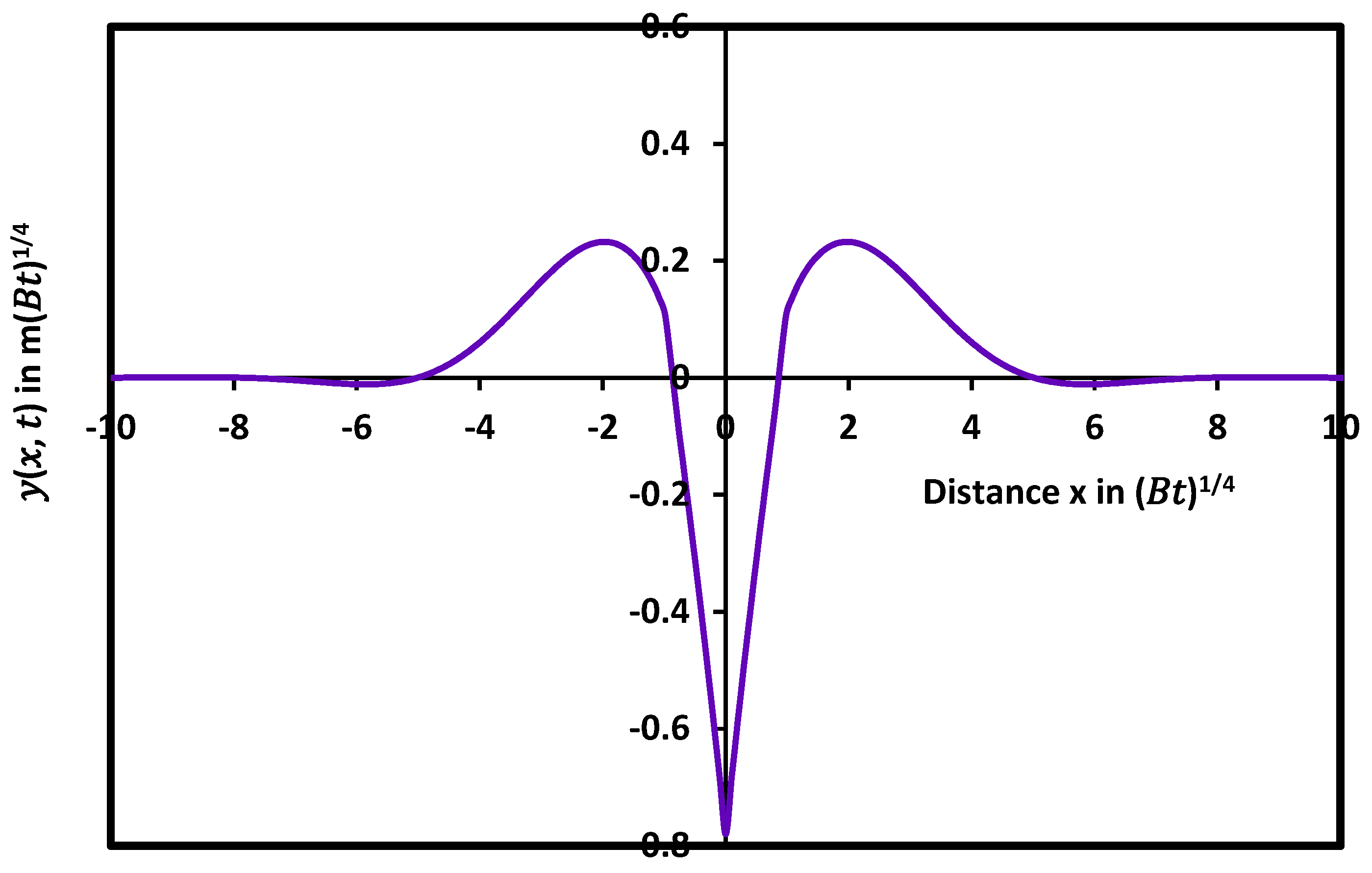
The mathematical solution given by equations 25-27 led to draw the variations of the profile y x ,   t on Figure 2 as a function of the distance x by taking the symmetric axis of the groove as the y-axis.
as a function of the distance x in the case of simultaneous effects of evaporation/condensation and diffusion.
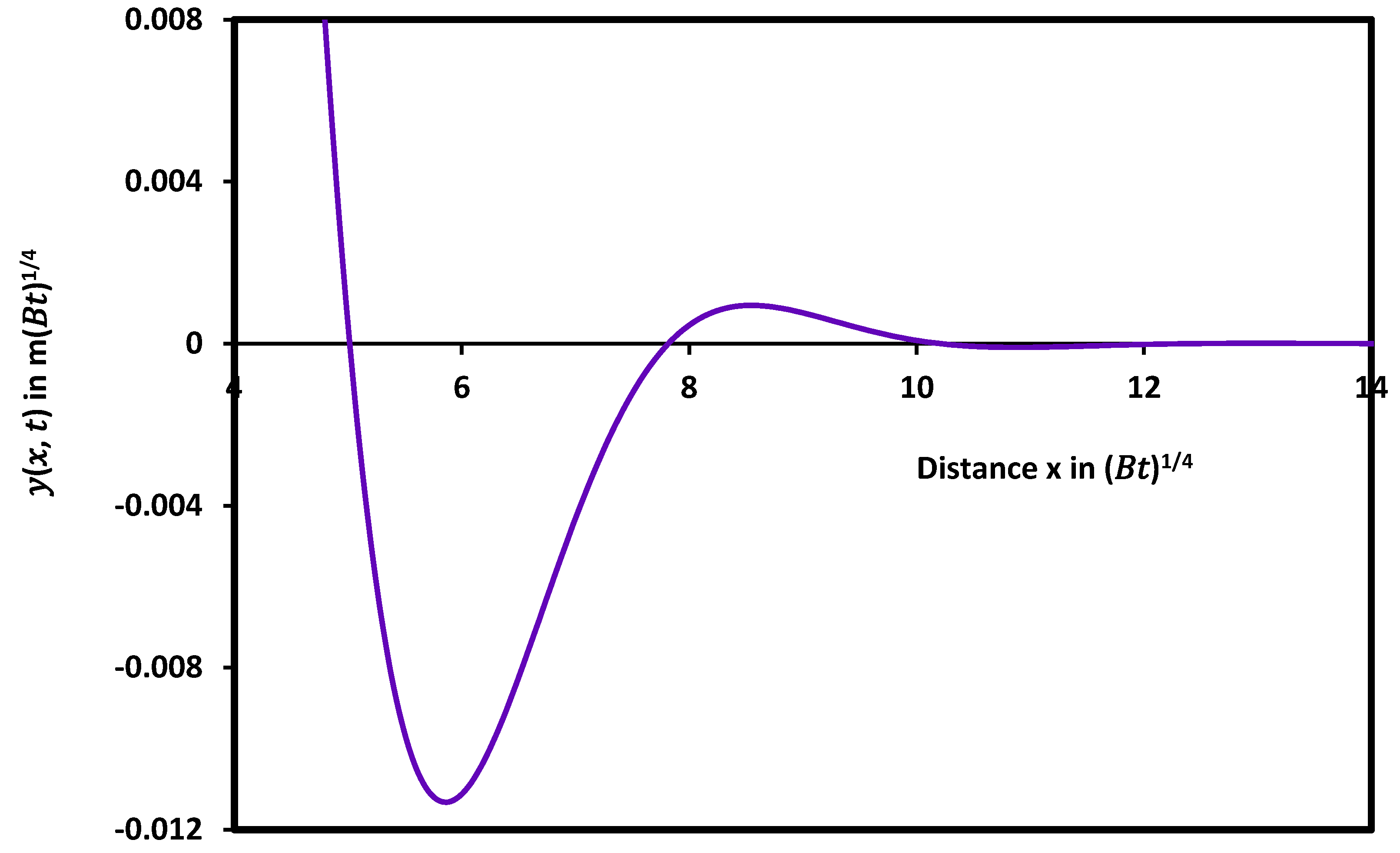
The evolution of y x ,   t in Figure 2 showed similar variations with the curve obtained with the diffusion case alone. A damped sinusoidal profile of the groove with an infinity of maxima, minima, and zeros of the solutions was revealed (Figure 3) with smaller oscillations. Figure 3 clearly showed the first minimum and the second maximum of the profile with a rapid decreasing amplitude with the distance x .
as a function of the distance x showing the first minimum and the second maximum of the profile.
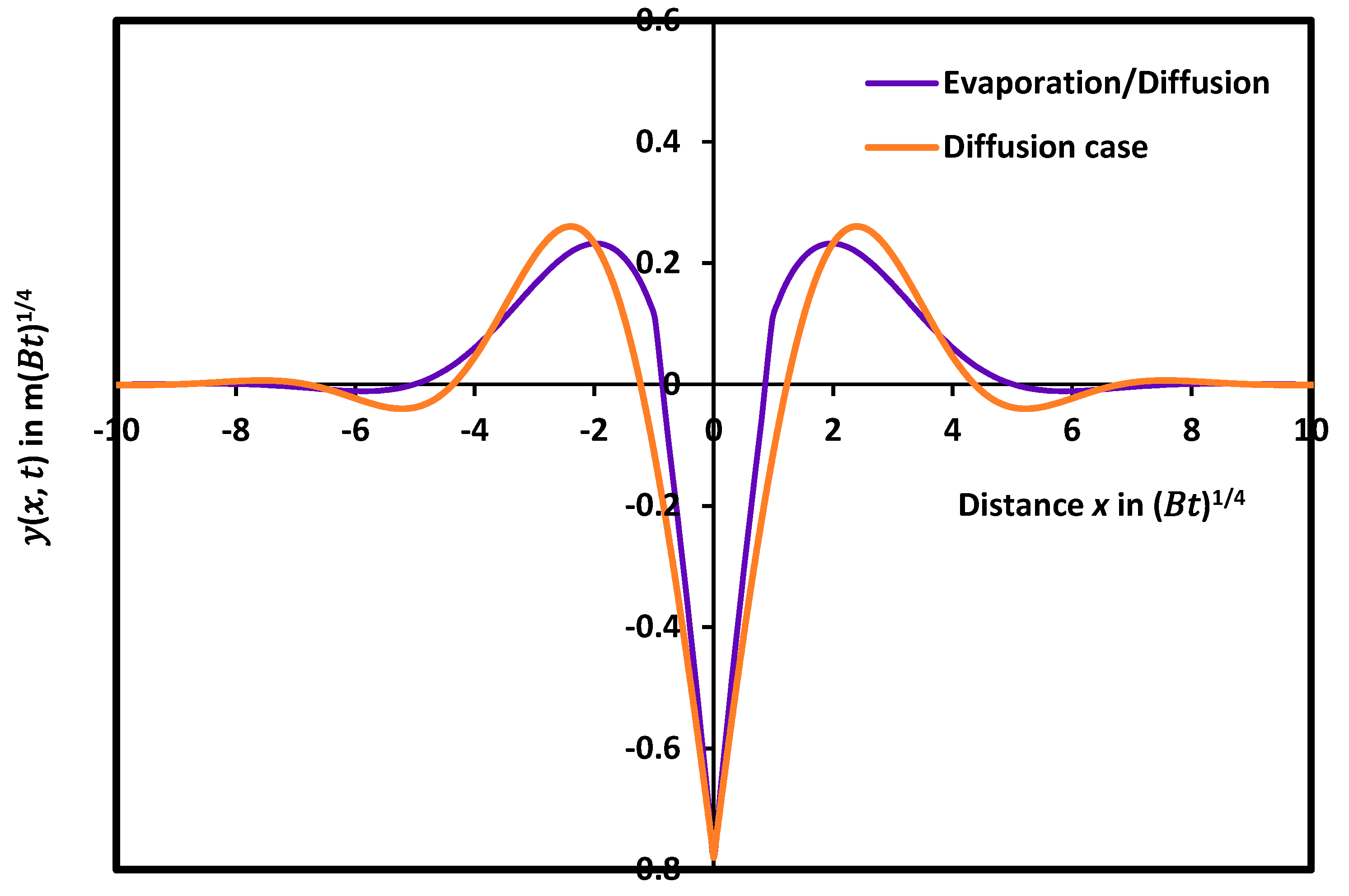
The curves relative to the comparison between the case of the diffusion alone and the combined evaporation and diffusion as a function of the distance, were plotted on Figure 4. The maximum h M a x of the grain profile in the combination evaporation and diffusion effects showed a decrease in its value with respect to the case of the diffusion alone. The same decrease was observed for the different maxima h M a x and minima h m i n of the function y x ,   t . However, the separation distance between two consecutive maxima d M a x or minima d m i n increased relative to the diffusion case.
The resulting variations of the different geometric characteristics of the grain profile in the diffusion alone and in the simultaneous case of evaporation/condensation and diffusion is certainly due to the thermal effect of the evaporation/condensation phenomenon. A decrease of the surface area of the groove profile was observed in the combined cases proving the important competition between the evaporation and diffusion.
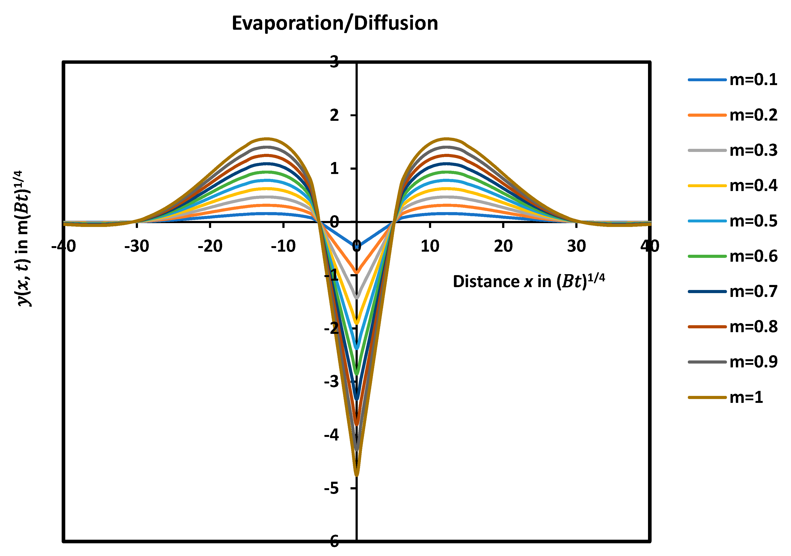
The effect of the slope m at origin on the shape of the groove profile was studied and shown in Figure 5. It was shown that the groove depth increases when the contact angle of the groove θ increases, while, the other characteristics such as d M a x and the width w M a x of the groove remain the same.
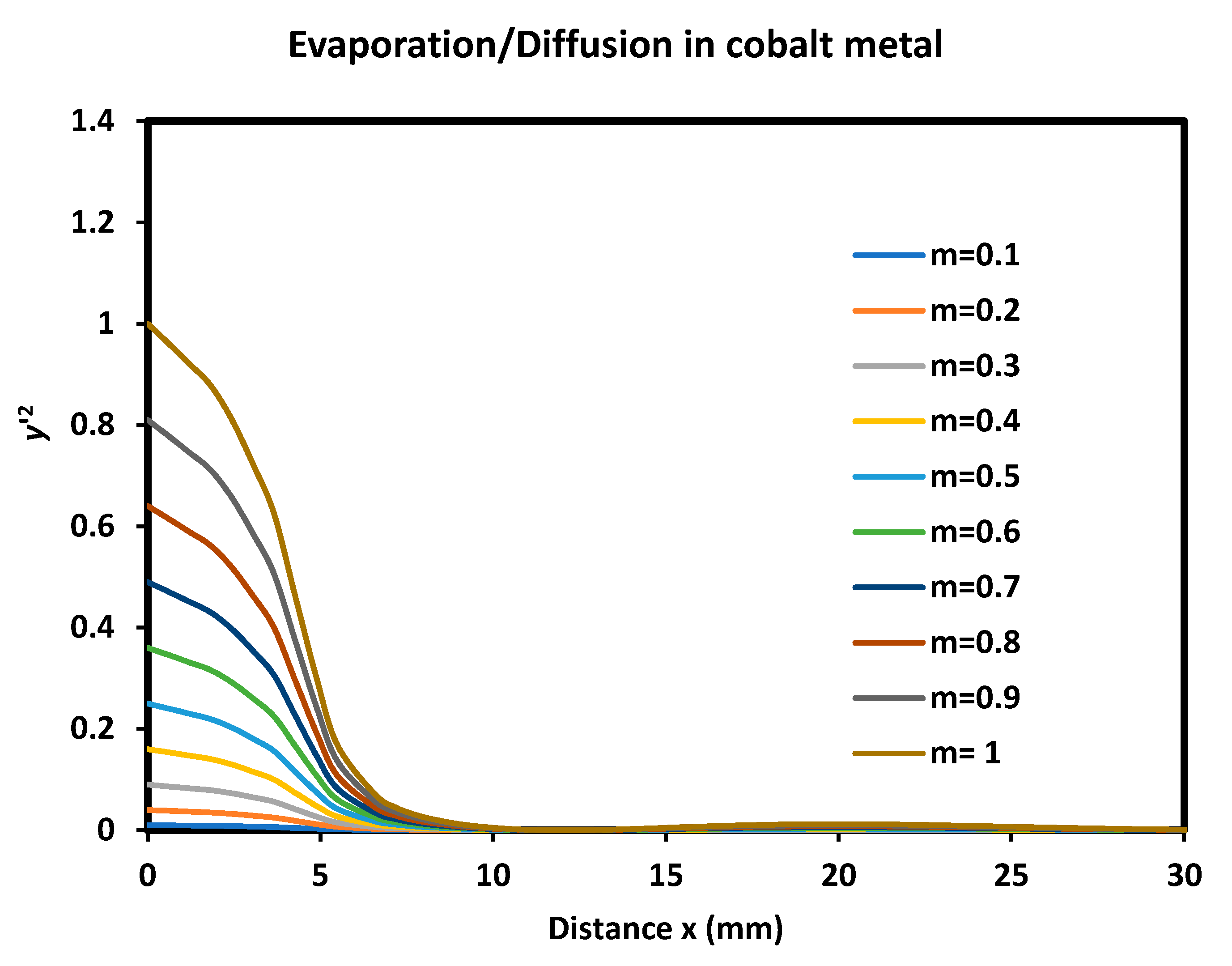
The analytical rigorous solution was obtained for y ' 2 1 . The variations of y ' 2 ( x ) versus the distance x were plotted in Figure 6. Two conclusions can be deduced from the curves of Figure 6. The first one was for the validity of the above approximation, it was concluded that the solution remains still valid even for all values of y ' 2 with the condition of contact angle of the groove less than 27.6°. Knowing that the contact angle was defined as the angle formed between the y-axis and the tangent at the origin of the groove, it can be deduced that the total contact angle of the groove can reach 54.2° without any loss on the analytical solution. The second conclusion was that the analytical solution remains valid for distances x 6   μ m even if y ' 2 is not neglected behind 1.

7. Analytical Solution by Using the Series Development

Equation 20 can be also written as follows:
g ' ' ' ' a g ' ' 1 4   u g ' + 1 4 g = 0  
By considering the development of g ( u ) in whole series as a function u , one writes:
g u = i = 0 a i u i
The different derivatives of the above whole series are given by Eq. 30:
u g ' u = i = 0 i a i u i
g ' ' u = i = 2 i i 1 a i u i 2 = i = 0 ( i + 1 ) ( i + 2 ) a i + 2 u i
g ' ' ' ' u = i = 4 i i 1 i 2 i 3 a i u i 4 = i = 0 ( i + 1 ) ( i + 2 ) ( i + 3 ) ( i + 4 ) a i + 4 u i
Equation 28 can be then transformed into the following equation for all values of u by replacing all derivatives by their developments:
i = 0 ( i + 1 ) ( i + 2 ) ( i + 3 ) ( i + 4 ) a i + 4 a i + 1 i + 2 a i + 2 1 4 i a i + 1 4 a i u i = 0 ,   u R
And one obtains a recurrent relation between the different terms a i of the series representing the function g u :
( i + 1 ) ( i + 2 ) ( i + 3 ) ( i + 4 ) a i + 4 a i + 1 i + 2 a i + 2 + 1 4 ( 1 i ) a i = 0 ,   i N
The complete determination of coefficients a i can be obtained by knowing the first four terms of the series a 0 , a 1 , a 2 , and a 3 . The other terms a i ,   i 4   can be deduced by recurrent relations. The boundary conditions of the grain grooving profile are used to determine the different terms of the series. Two types of boundary conditions can be applied: the first one was proposed by Mullins [14,15] and the second one by Amram et al. [54].
The use of the boundary conditions obtained by Mullins led to the following relations:
a 0 = 1 2 × Γ 5 / 4                                                       a 1 = 1                                     a 2 = 1 8 2 × Γ 5 4   a 3 = 0                                  
Using relation a 2 = a 0 8 and Eq. 31, one obtained the expression of a 4 as a function of the evaporation/diffusion coefficient a :
a 4 = a 1   a 0 4 ! × 4 = ( a 1 ) 4 ! × 4 2 × Γ 5 4
The calculations proved that the odd terms of the series are zero and one writes:
  a 2 n + 1 = 0   n N
The even terms are given by the following recurrent relation:
  a 2 n = 4 a 2 n 3 2 n 2 a 2 n 2 ( 2 n 5 ) a 2 n 4 8 n 2 n 1 2 n 2 2 n 3 = 0 ,   n N
Therefore, the analytical solution g u = i = 0 a i u i was fully determined and obviously convergent towards zero.
By using the boundary conditions proposed by Amram et al. [54], one writes Eqs. 35
a 0 = 2 Γ 5 / 4                                                       a 1 = 1                       a 2 = 0                         a 3 = 1 6 π      
This allowed to give the value of a 4 = a 0 96 and the recurrent formula giving all values a n :
  a n + 4 = 4 a n + 1 n + 2 a n + 2 + ( n 1 ) a n 4 ( n + 1 ) n + 2 n + 3 n + 4 = 0 ,   n N
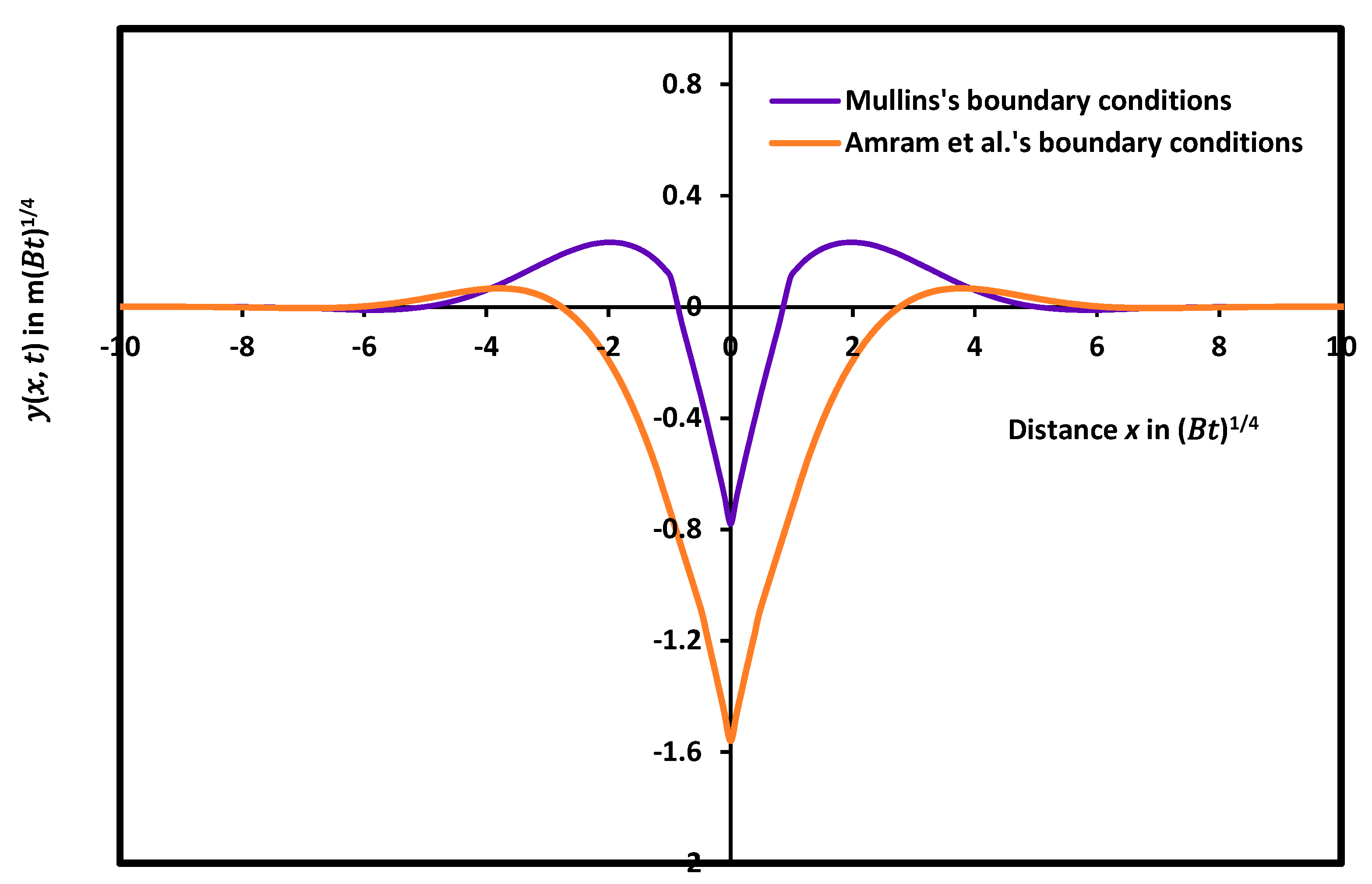
It was found that the boundary conditions proposed by Mullins [12,13] and Amram et al. [54] gave very large difference between the two solutions. Figure 7 showed that the maximum of the groove with the boundary conditions of Amram et al. was four times smaller than that obtained by using the boundary conditions of Mullins, whereas the grain groove deep was twice deeper than that of Mullins’s conditions. All geometric characteristics of the grain groove profile are affected by the change of the boundary conditions. It seems that the classical Mullins-type groove growing by surface diffusion alone cannot be satisfied by the presence of evaporation/condensation process. The correction made by this present work represents a key microstructural element of thin metal polycrystalline films and in many cases participates to the determination of their physical, mechanical and functional properties

7. Conclusion

A new analytical solution of the partial differential equation y t = C y ' ' B y ' ' ' ' was proposed in the combined cases of evaporation/condensation and diffusion in polycrystalline thin films. A detailed mathematical method was given. The found solution showed a damped sinusoidal groove profile in the case of electronic power devices, less attenuated than the case of the diffusion alone. The determination of the groove profile y x ,   t and its derivatives allowed to conclude that the validity of the new mathematical solution can be extended to the domain located out of that relative to the approximation y ' 2 1 . Indeed, the obtained solution is valid even if the contact angle of the groove is greater than 30° for distance x greater than 6 mm. The values of the maxima and minima obtained in the combination cases of evaporation and diffusion were found less than those obtained with diffusion alone proving the capital role of the evaporation/condensation phenomenon. The analytical expressions of the groove profile and its derivatives led to the determination of all geometric characteristics of the grain groove profile and can be therefore used to study the effect of the combined effects of evaporation and diffusion on metals. Another analytical solution based on series development was found. All terms of the series representing the function g ( u ) and then y ( x , t ) were determined by using the Mullins and Amram et al. boundary conditions. The obtained results showed the important role of these conditions on the geometric characteristics of the groove profile.

Author Contributions

T.H.: conceptualization; formal analysis; investigation; methodology; supervision; validation; writing—review. A.I.: editing; investigation; methodology. conceptualization; validation; review. Z.K.: conceptualization; formal analysis; investigation and review. All authors have read and agreed to the published version of the manuscript.

Funding

This research received no external funding.

Data Availability Statement

No other data available.

Conflicts of Interest

The authors declare no conflict of interest.

Appendix A

To resolve equation (6), we used the same method developed in previous study [53] by transforming equation (6) into difference between two perfect squares and then to transform the expression 8 μ + 4 a r 2 + u   r + 4 μ 2 1 into perfect square, it has to have double solution and then his discriminant has to be cancelled.
Now, considering the following equation:
8 μ + 4 a r 2 + u   r + 4 μ 2 1 = 0
And cancelling the discriminant this second-degree equation function in r, one obtains:
= u 2 16   2 μ + a 4 μ 2 1
Putting = 0 one has:
μ 3 + a 2 μ 2 1 4 μ u 2 + 16 a 128 = 0
By choosing μ = η a 6 , one obtains:
η 3 a 2 + 3 12 η + 32   a   a 3 9 27   u 2 128 * 27 = 0
Equation (A4) can be written as general form:
η 3 + p η + q = 0
With p = a 2 + 3 12 and q = + 32 a 3 9 a 27 u 2 128 * 27 Putting η = α + β and taking α β = p 3 or α 3 β 3 = p 3 27 one obtains:
α 3 + β 3 = q And α 3 et β 3 will be the solutions of the following second-degree equation A6:
X 2 + q X p 3 27 = 0
With the following discriminant:
η = 27 q 2 + 4 p 3 27 = 32   a 3 9 a 27   u 2 2 7 *   3 3 2 4 27 a 2 + 3 2 2 *   3 3
or
η = 27 q 2 + 4 p 3 27 = 32   a 3 9 a 27   u 2 2 2 10 a 2 + 3 3 2 14 *   3 6
η =   a 1 u 2 2 a 2 2 2 14                                                     a 1 = 2 5   a 3 9 a 3 3 ;   a 3 9 a > 0 a 2 2 = 2 10 3 6 a 2 + 3 3                                              
Therefore:
q = a 1 u 2 128
p = a 2 + 3 12
Two cases have to be considered:
η > 0 u > a 1 + a 2 η < 0 u < a 1 + a 2
The limit value of u is given by:
u 0 = a 1 + a 2
  • 1. First case  η > 0  for u  > u 0
In this case, one obtains:
α 3 = q + η 2   and   β 3 = q η 2
One writes:
α 3 = a 1 u 2 + a 1 u 2 2 a 2 2 2 8 β 3 = a 1 u 2 a 1 u 2 2 a 2 2 2 8
This leads to the solution of equation (A5):
η = α + β
And the solution of equation (104):
μ = α + β a 6
This value of µ will cancel the discriminant of equation (A1). The solution r is then given by:
r = u 8   2 μ + a
Therefore:
8 μ + 4 a r 2 + u   r + 4 μ 2 1 = 4 2 μ + a r + u 8   2 μ + a 2
Knowing that 2 μ + a < 0 , one obtains:
E r = r 4 a   r 2 1 4 u   r + 1 4 = r 2 + μ 2 2 μ + a r + u 8   2 μ + a 2
And in complex development:
E r = r 2 + μ i   2 μ a   r + u 8 2 μ + a r 2 + μ + i   2 μ a   r + u 8 2 μ + a
One deduced that in this case, the four solutions will be complex. The solutions of equation (A18) are equivalent to the solutions of the two following equations:
r 2 i   2 μ a   r + μ i u 2 μ a 8 2 μ + a = 0
r 2 + i   2 μ a   r + μ + i u 2 μ a 8 2 μ + a = 0
The discriminants of equations (A19) and (A20) are given by the respective following expressions:
1 = a 2 μ + i u 2 μ a 2 2 μ + a
2 = a 2 μ i u 2 μ a 2 2 μ + a
The two discriminants can be given as:
1 = ρ   e i θ       2 = ρ   e i θ
The cases studied here are obtained for u > u 0 . The four complex solutions are then given by:
r 1 = ρ 1 / 2   c o n θ 2 + i 2 μ a + s i n θ 2 2 r 2 = ρ 1 / 2   c o n θ 2 + i 2 μ a s i n θ 2 2 r 3 = ρ 1 / 2   c o n θ 2 i 2 μ a + s i n θ 2 2 r 4 = ρ 1 / 2   c o n θ 2 i 2 μ a s i n θ 2 2
Now, the solution in this case for u > u 0 , is given by:
g 1 u = E x p ρ 1 2   c o n θ 2 A 11 c o s 2 μ a s i n θ 2   u + A 21 s i n 2 μ a s i n θ 2   u
+ E x p ρ 1 / 2   c o n θ 2 u A 31 c o s 2 μ a + s i n θ 2   u + A 41 s i n 2 μ a + s i n θ 2   u
The following boundary conditions
1 )   lim u g u = 0                                             2 )     lim u g ' u = 0                                           3 ) lim u g ' ' u = 0                                            
Allowed to deduce the following parameters:
A 31 = A 41 = 0
And the final solution is therefore given by:
g 1 u = E x p ρ 1 / 2   c o s θ 2 u A 11 c o s 2 μ a s i n θ 2   u + A 21 s i n 2 μ a s i n θ 2   u
Where:
ρ = ( a 2 μ ) 2 u 2 2   ( a + 2 μ ) ρ 1 / 2   c o n θ 2 = ρ + a 2 μ 2 s i n θ 2 = ρ a + 2 μ 2   ρ                      
Equation A27 can be written in general form as:
g 1 u = e p 1 ( u )   A 11 c o s   q 1 ( u ) + A 21 s i n   q 1 ( u )
With :
p 1 u = ρ + a 2 μ 2 u                                                                   q 1 u = 2 μ a ρ a + 2 μ 2   ρ u
Where a 2 2 , α 3 , β 3 , and μ are respectively given by Eqs. A9, A12 and A14.
The three first derivatives of the function g 1 u are given by the following equations:
g 1 ' u = p 1 '   A 11 cos q 1 + A 21 sin q 1 e p 1 + q 1 '   A 21 cos q 1 A 11 sin q 1 e p 1
g 1 ' ' u = p 1 ' 2 q 1 ' 2 p 1 ' ' A 11 cos q 1 + A 21 sin q 1 e p 1 + q 1 ' '   2   p 1 ' q 1 '   A 21 cos q 1 A 11 sin q 1 e p 1
g 1 ' ' ' u = 3 p 1 ' p ' ' 3 q 1 ' q 1 ' ' p 1 ' ' ' p 1 ' 3   + 3   p 1 ' q 1 ' 2 A 11 cos q 1 + A 21 sin q 1 e p 1 + 3 p 1 ' 2 q 1 ' q 1 ' 3 3 p 1 ' ' q 1 ' + q 1 ' ' ' 3 p 1 ' q 1 ' ' A 21 cos q 1 A 11 sin q 1 e p 1
  • 2. Second case  η < 0  for  u < u 0
In this case, one obtains:
α 3 = ρ   e i ω       β 3 = ρ   e i ω
Where ρ 2 = α 3 2 = β 3 2 = a 2 2 2 16 = a 2 + 3 3 2 6 × 3 6 , and ρ = a 2 + 3 3 / 2 2 3 × 3 3 and finally, ρ 1 / 3 = a 2 + 3 6 With:
η = a 2 + 3 3 c o s ω 3 = 2   ρ 1 / 3 c o s ω 3                                 ρ   c o s   ω = a 1 u 2 2 8   ;   ρ = a 2 + 3 3 / 2 2 3 × 3 3                                 ρ   s i n   ω = a 2 2 a 1 u 2 2 2 8                                                                        
And the solution of equation (A1):
μ = η a 6
This value of µ will cancel the discriminant of equation (A1). The solution r is given by:
r = u 8   2 μ + a
The expression E r can be given by:
E r = r 2 + 2 μ + a   r + μ + u 8 2 μ + a r 2 2 μ + a   r + μ u 8 2 μ + a
And therefore:
r 2 + 2 μ + a   r + μ + u 8 2 μ + a = 0                                 r 2 2 μ + a   r + μ u 8 2 μ + a = 0                                
The discriminants of equations (A35) are given by the respective following expressions:
1 = a 2 μ u 2 a + 2 μ                                 2 = a 2 μ + u 2 a + 2 μ                                
In this case, one has:
μ = η a 6 = a 2 + 3 3 c o s ω 3 a 6
μ = 2   ρ 1 / 3 c o s ω 3 a 6
Two cases can be studied:
First case:  r 2 + 2 μ + a r + μ + u 8 2 μ + a = 0
Where 1 = a 2 μ u 2 a + 2 μ is positive for u < u 0
r 1 = 1 2 2 μ + a + a 2 μ u 2 a + 2 μ
r 2 = 1 2 2 μ + a a 2 μ u 2 a + 2 μ
Second case:  r 2 2 μ + a r + μ u 8 2 μ + a = 0
Where 2 = a 2 μ + u 2 a + 2 μ is positive for u < u 0
The two other solutions are then given by
r 3 = 1 2 2 μ + a + a 2 μ + u 2 a + 2 μ
r 4 = 1 2 2 μ + a a 2 μ + u 2 a + 2 μ
Now, the final solution for u < u 0 , is given by: g 2 u = e 1 2 × 2 μ + a   u A 12 E x p 1 2 × a 2 μ u 2 a + 2 μ   u + A 22 E x p 1 2 × a 2 μ u 2 a + 2 μ   u
+ e 1 2 × 2 μ + a   u A 32 E x p 1 2 × a 2 μ + u 2 a + 2 μ   u + A 42 E x p 1 2 × a 2 μ + u 2 a + 2 μ   u
Putting:
l u = 1 2 2 μ ( u ) + a ;   p u = l ( u )   u
q 1 u = 1 2 × a 2 μ u 2 a + 2 μ   u   or   q 1 u = 1 2 a 2 μ u ( l u ) 1 4   u
q 2 u = 1 2 × a 2 μ + u 2 a + 2 μ   u   or   q 2 u = a 2 μ + u ( l u ) 1 4   u
One obtains for u < u 0 the following solution g 2 u
g 2 u = e p ( u ) A 12 e q 1 u + A 22 e q 1 u + e p ( u ) A 32 e q 2 u + A 42 e q 2 u
In conclusion, for   u > u 0
g 1 u = E x p ρ 1 / 2   c o n θ 2 A 11 c o s 2 μ a s i n θ 2   u + A 21 s i n 2 μ a s i n θ 2   u
g 1 u = e p 1 ( u )   A 11 c o s   q 1 ( u ) + A 21 s i n   q 1 ( u )
With
p 1 u = ρ 1 / 2   c o n θ 2 u   ;   q 1 u = 2 μ a s i n θ 2   u
l 1 u = 2 μ u a 1 / 2 ;     ;   μ = η a 6 ;   η = α + β
α 3 = a 1 u 2 + a 1 u 2 2 a 2 2 2 8
β 3 = a 1 u 2 a 1 u 2 2 a 2 2 2 8
And for u < u 0
g 2 u = e p ( u ) A 12 e q 1 u + A 22 e q 1 u + e p ( u ) A 32 e q 2 u + A 42 e q 2 u
l u = 1 2 2 μ ( u ) + a ;   p u = l ( u )   u
q 1 u = 1 2 × a 2 μ u 2 a + 2 μ   u   or   q 1 u = 1 2 × a 2 μ u ( l u ) 1 4   u
q 2 u = 1 2 × a 2 μ + u 2 a + 2 μ   u   or   q 2 u = a 2 μ + u ( l u ) 1 4   u
l u = 1 2 2 μ ( u ) + a ;   p u = 1 2 2 μ + a   u = u l ( u )   ;   μ = η a 6
The three first derivatives of g 2 u are given below:
g ' 2 = e p p ' + q ' 1   A 12 e q 1 p ' + q ' 1 A 22 e q 1 + e p p ' + q ' 2 A 32 e q 2 + p ' q ' 2 A 42 e q 2
g ' ' 2 = e p p ' q ' 1 2 p ' ' + q ' ' 1   A 12 e q 1 + p ' + q ' 1 2 p ' ' q ' ' 1 A 22 e q 1 + e p p ' + q ' 2 2 + p ' ' + q ' ' 2   A 32 e q 2 + p ' q ' 2 2 + p ' ' q ' ' 2 A 42 e q 2
g ' ' ' 2 = e p p ' + q ' 1 3 + 3 p ' p ' ' 3 p ' q ' ' 1 3 p ' ' q ' 1 + 3 q ' 1 q ' ' 1 p ' ' ' + q ' ' ' 1   A 12 e q 1 + p ' q ' 1 3 + 3 p ' p ' ' + 3 p ' q ' ' 1 + 3 p ' ' q ' 1 + 3 q ' 1 q ' ' 1 p ' ' ' q ' ' ' 1 A 22 e q 1 + e p p ' + q ' 2 3 + 3 p ' p ' ' + 3 p ' q ' ' 2 + 3 p ' ' q ' 2 + 3 q ' 2 q ' ' 2 + p ' ' ' + q ' ' ' 2   A 32 e q 2 + p ' q ' 2 3 + 3 p ' p ' ' 3 p ' q ' ' 2 3 p ' ' q ' 2 + 3 q ' 2 q ' ' 2 + p ' ' ' q ' ' ' 2 A 42 e q 2
And the function g and its different derivatives are given by the following boundary conditions at point 0:
g 0 = 1 2 × Γ 5 / 4                                                                             g ' 0 = 1                                                                                 g ' ' 0 = 1 4 2 × Γ 5 4 = g 0 4                                                                                                                                   g ' ' ' 0 = 0                                                                
The expressions of the function g 2 and derivatives in 0 are given below as a function of the different parameters Aij
g 2 0 = A 12 + A 22 + A 32 + A 42 = g 0 = 1 2 Γ 5 / 4
g ' 2 0 = p ' + q ' 1   A 12 p ' + q ' 1 A 22 + p ' + q ' 2 A 32 + p ' q ' 2 A 42 = 1
g ' ' 2 0 = p ' q ' 1 2 p ' ' + q ' ' 1   A 12 + p ' + q ' 1 2 p ' ' q ' ' 1 A 22
+ p ' + q ' 2 2 + p ' ' + q ' ' 2   A 32 + p ' q ' 2 2 + p ' ' q ' ' 2 A 42 = g 0 4
g ' ' ' 2 0 = p ' + q ' 1 3 + 3 p ' p ' ' 3 p ' q ' ' 1 3 p ' ' q ' 1 + 3 q ' 1 q ' ' 1 p ' ' ' + q ' ' ' 1   A 12 + p ' q ' 1 3 + 3 p ' p ' ' + 3 p ' q ' ' 1 + 3 p ' ' q ' 1 + 3 q ' 1 q ' ' 1 p ' ' ' q ' ' ' 1 A 22 + p ' + q ' 2 3 + 3 p ' p ' ' + 3 p ' q ' ' 2 + 3 p ' ' q ' 2 + 3 q ' 2 q ' ' 2 + p ' ' ' + q ' ' ' 2   A 32 + p ' q ' 2 3 + 3 p ' p ' ' 3 p ' q ' ' 2 3 p ' ' q ' 2 + 3 q ' 2 q ' ' 2 + p ' ' ' q ' ' ' 2 A 42 = 0
Taking:
p u = 1 2 2 μ ( u ) + a   u   ; l u = 1 2 2 μ ( u ) + a and p u = l ( u )   u ; one obtains the different derivatives of l ( u ) and p u :
l ' = 1 2 μ ' 2 μ + a ;   l ' ' = 1 2 μ ' ' 2 μ + a 1 / 2 μ ' 2 2 μ + a 3 / 2
l ' ' ' = 1 2 μ ' ' ' 2 μ + a 1 2 3 μ ' μ ' ' 2 μ + a 1 2 + 3 μ ' 3 2 μ + a 5 / 2
p ' = l + l '   u   ;   p ' ' = 2 l ' + l ' '   u   ;   p ' ' ' = 3 l ' ' + l ' ' '   u
Putting:
q 1 u = 1 2 a 2 μ u 2 a + 2 μ   u   or   q 1 u = 1 2 a 2 μ u ( l u ) 1 4   u   ;   q 1 u = 1 2 m 1 ( u ) u ;   m 1 ( u ) = a 2 μ u 2 a + 2 μ = a 2 μ u l 1 4
One obtains the derivatives of m 1 ( u ) and q 1 u :
m 1 ' = 1 4   l 1 + u   l ' l 2 2 μ '       m 1 ' ' = 1 4   2 l ' l 2 + l ' ' l 2 u 2 l ' 2 l 3 u 2 μ ' '     m 1 ' ' ' = 1 4   u   l ' ' ' l 2 6 l ' l ' ' l 3 u 6 l ' 2 l 3 + 6 l ' 3 l 4 u + 3 l ' ' l 2 2 μ ' ' '    
q 1 ' = 1 2 1 2   m 1 ' m 1 1 2 u + m 1 1 / 2           q 1 ' ' = 1 2 1 2   m 1 ' ' m 1 1 2 u 1 4   m 1 ' 2 m 1 3 2 u + m 1 ' m 1 1 2     q 1 ' ' ' = 1 2 1 2   m 1 ' ' ' m 1 1 2 u 3 4   m 1 ' m 1 ' ' m 1 3 2 u + 3 8   m 1 ' 3 m 1 5 2 u + 3 2   m 1 ' ' m 1 1 2 3 4   m 1 ' 2 m 1 3 2    
The same procedure was used with m 2 ( u ) and q 2 u :
q 2 u = 1 2 a 2 μ + u 2 a + 2 μ   u   or   q 2 u = 1 2 a 2 μ + u ( l u ) 1 4   u   ;   q 2 u = 1 2 m 2 ( u ) u ;   m 2 a 2 μ + u l 1 4
m 2 ' = 1 4   l 1 + u   l ' l 2 2 μ '       m 2 ' ' = 1 4   2 l ' l 2 + l ' ' l 2 u 2 l ' 2 l 3 u 2 μ ' '     m 2 ' ' ' = 1 4   u   l ' ' ' l 2 6 l ' l ' ' l 3 u 6 l ' 2 l 3 + 6 l ' 3 l 4 u + 3 l ' ' l 2 2 μ ' ' '    
q 2 u = 1 2 m 2 ( u ) u
q 2 ' = 1 2 1 2   m 2 ' m 2 1 2 u + m 2 1 / 2           q 2 ' ' = 1 2 1 2   m 2 ' ' m 2 1 2 u 1 4   m 2 ' 2 m 2 3 2 u + m 2 ' m 2 1 2     q 2 ' ' ' = 1 2 1 2   m 2 ' ' ' m 2 1 2 u 3 4   m 2 ' m 2 ' ' m 2 3 2 u + 3 8   m 2 ' 3 m 2 5 2 u + 3 2   m 2 ' ' m 2 1 2 3 4   m 2 ' 2 m 2 3 2    
Values in 0 for   q 1 u   and all derivatives
l 0 = 1 2 2 μ ( 0 ) + a   ;   p 0 = 0   ;   q 0 = 0   ;   m 0 = a 2 μ ( 0 )
μ 0 = 2   ρ 1 / 3 c o s ω ( 0 ) 3 a 6
μ ' 0 = 0             μ ' ' 0 = 1 2 6 ρ 2 3 s i n ω 3 s i n   ω ( 0 )               μ ' ' ' 0 = 0                            
l 0 = 1 2 2 μ ( 0 ) + a
l ' 0 = 0             l ' ' ( 0 ) = 1 2 μ ' ' ( 0 ) 2 μ ( 0 ) + a 1 / 2               l ' ' ' 0 = 0    
p 0 = 0   ;   p ' 0 = l ( 0 )   ;   p ' ' 0 = 0   ;   p ' ' ' 0 = 3 l ' ' ( 0 )
m 1 0 = a 2 μ ( 0 )
m 1 ' 0 = 1 4   l 0 1 m 1 ' ' 0 = 2 μ ' ' 0 = 2 2 6 ρ 2 3 s i n ω 3 s i n   ω ( 0 )     m 1 ' ' ' u = 3 4   l ' ' 0 l 0 2      
well-verified
q 1 0 = 0
q 1 ' ( 0 ) = 1 2 m 1 ( 0 ) 1 2 q 1 ' ' ( 0 ) = 1 2 m 1 ' ( 0 ) 1 2 q 1 ' ' ' ( u ) = 1 2 [ 3 2 m 1 ' ' ( 0 ) m 1 ( 0 ) 1 2 3 4 m 1 ' ( 0 ) 2 m 1 ( 0 ) 3 2
Values of different parameters at point 0 and derivatives
l 0 = 1 2 2 μ ( 0 ) + a   ;   p 0 = 0   ;   q 0 = 0   ;   m 0 = a 2 μ ( 0 )
μ 0 = 2   ρ 1 / 3 c o s ω ( 0 ) 3 a 6
μ ' 0 = 0             μ ' ' 0 = 1 2 6 ρ 2 3 s i n ω 3 s i n   ω ( 0 )               μ ' ' ' 0 = 0                            
l 0 = 1 2 2 μ ( 0 ) + a
l ' 0 = 0             l ' ' ( 0 ) = 1 2 μ ' ' ( 0 ) 2 μ ( 0 ) + a 1 / 2               l ' ' ' 0 = 0    
p 0 = 0
p ' 0 = l ( 0 )   ;   p ' ' 0 = 0   ;   p ' ' ' 0 = 3 l ' ' ( 0 )
m 2 0 = a 2 μ ( 0 )
m 2 ' 0 = 1 4   l 0 1 m 2 ' ' 0 = 2 μ ' ' 0 = 2 2 6 ρ 2 3 s i n ω 3 s i n   ω ( 0 )     m 2 ' ' ' u = 3 4   l ' ' 0 l 0 2      
q 2 0 = 0 q 2 ' 0 = 1 2 m 2 ( 0 ) 1 / 2           q 2 ' ' 0 = 1 2 m 2 ' 0 m 2 0 1 2     q 2 ' ' ' 0 = 1 2 3 2   m 2 ' ' 0 m 2 0 1 2 3 4   m 2 ' 0 2 m 2 0 3 2    
Comparison between parameters in 0
m 2 0 = m 1 ( 0 ) m 2 ' 0 = m 1 ' ( 0 ) m 2 ' ' 0 = m 1 ' ' ( 0 )     m 2 ' ' ' u = m 1 ' ' ' ( 0 )       q 2 0 = q 1 0 q 2 ' 0 = q 1 ' 0           q 2 ' ' 0 = q 1 ' ' 0 q 2 ' ' ' 0 = q 1 ' ' ' 0    
Calculation of the different derivatives of  μ
Knowing that η = 2 ρ 1 / 3 c o s ω 3 ; c o s ω = a 1 2 u 2 2 8 ρ and s i n ω = b 1 2 a 1 2 u 2 2 2 8 ρ , one obtains: η ' u = d η d u = d η d ω . d ω d u ; d ω d u = 2 ρ 1 / 3 s i n ω 3 ; d ω d u = 2 7 ρ s i n ω u and then the first derivative η ' u :
μ ' u = η ' u = 1 2 6 ρ 2 / 3 s i n ω 3 s i n   ω   u
μ ' u = 1 2 6 ρ 2 / 3 s i n ω 3 s i n ω u ; let’s put v ω = s i n ω 3 s i n ω ; therefore, μ ' ' u = 1 2 6 ρ 2 / 3 v + u d v d u
μ ' ' u = 1 2 6 ρ 2 / 3   v + u   d v d u     ;   d v d u = d v d ω   d ω d u = d d ω s i n ω 3 s i n   ω × 2 7 ρ   s i n   ω u
Knowing that: d d ω s i n ω 3 s i n ω = 3 1 s i n ω c o s ω 3 3 c o s ω s i n ω 3 s i n 2 ω , one obtains:
d v d u = 3 1 s i n   ω   c o s ω 3 3 c o s   ω   s i n ω 3 s i n 2   ω × 2 7 ρ   s i n   ω u
μ ' ' u = 1 2 6 ρ 2 / 3   s i n ω 3 s i n   ω + 3 1 s i n   ω   c o s ω 3 3 c o s   ω   s i n ω 3 s i n 2   ω × 2 7 ρ   s i n   ω u 2  
μ ' ' u = 1 2 6 ρ 2 / 3   s i n ω 3 s i n   ω u 2 3 × 2 7 ρ s i n   ω   c o s ω 3 3 c o s   ω   s i n ω 3 s i n 3   ω  
By using s i n a c o s b = sin a + b + sin a b 2 , one obtains:
s i n   ω   c o s ω 3 3   s i n ω 3   c o s   θ s i n 3   ω = 2 s i n 2 ω 3 s i n 4 ω 3   s i n 3   ω
and therefore:
μ ' ' u = 1 2 6 ρ 2 / 3   s i n ω 3 s i n   ω u 2 3 × 2 7 ρ 2 s i n 2 ω 3 s i n 4 ω 3   s i n 3   ω  
μ ' ' ' u = 1 2 6 ρ 2 / 3   d v d u + u 3 × 2 6 ρ 2 s i n 2 ω 3 s i n 4 ω 3   s i n 3   ω + u 2 3 × 2 7 ρ d d ω 2 s i n 2 ω 3 s i n 4 ω 3   s i n 3   ω × 2 7 ρ   s i n   ω u  
Using d v d u = u 2 3 × 2 7 ρ 2 s i n 2 ω 3 s i n 4 ω 3 s i n 3 ω , one obtains:
μ ' ' ' u = 1 2 6 ρ 2 / 3   u 2 3 × 2 7 ρ 2 s i n 2 ω 3 s i n 4 ω 3   s i n 3   ω + u 3 × 2 6 ρ 2 s i n 2 ω 3 s i n 4 ω 3   s i n 3   ω u 3 3 × 2 14 ρ 2 s i n   ω d d ω 2 s i n 2 ω 3 s i n 4 ω 3   s i n 3   ω  
With
d d ω 2 s i n 2 ω 3 s i n 4 ω 3   s i n 3   ω = 1 6 × 35     s i n ω 3 14   s i n 5 ω 3 + 5   s i n 7 ω 3   s i n 4   ω
One writes:
μ ' ' ' u = 1 2 6 ρ 2 / 3   u 3 × 2 6 ρ 2 s i n 2 ω 3 s i n 4 ω 3   s i n 3   ω u 2 3 × 2 7 ρ 2 s i n 2 ω 3 s i n 4 ω 3   s i n 3   ω u 3 3 2 × 2 15 ρ 2 × 35     s i n ω 3 14   s i n 5 ω 3 + 5   s i n 7 ω 3   s i n 5   ω  
Values of the successive derivatives of μ in u=0
μ 0 = 2   ρ 1 / 3 c o s ω ( 0 ) 3 a 6
μ ' u = 0
μ ' ' u = 1 2 6 ρ 2 3 s i n ω 3 s i n   ω ( 0 )
μ ' ' ' u = 0

References

  1. Zibo Chen, Alex Q. Huang, Extreme high efficiency enabled by silicon carbide (SiC) power devices, Materials Science in Semiconductor Processing, 2024, 172. [CrossRef]
  2. J. Millán, P. Godignon, X. Perpiñà, A. Pérez-Tomás, J. Rebollo, A survey of wide bandgap power semiconductor devices, IEEE Trans. Power Electron., 2014, 29 (5), 2155-2163.
  3. X. Li, et al. Achieving zero switching loss in silicon carbide MOSFET, IEEE Trans. Power Electron., 2019, 34 (12), 12193-12199.
  4. Cui, T., Mukherjee, S., Sudeep, P.M. et al. Fatigue of graphene. Nat. Mater. 2020, 19, 405–411. [CrossRef]
  5. Mughrabi, H. Fatigue, an everlasting materials problem - still en vogue, Proc. Eng., 2010, 2, 3-26.
  6. Sangid, M.D. The physics of fatigue crack initiation, Int. J. Fatigue, 2013, 57, 58-72.
  7. Zhang, Y. , Udrea, F. & Wang, H. Multidimensional device architectures for efficient power electronics. Nat Electron 2022, 5, 723–734. [Google Scholar] [CrossRef]
  8. Jin, Q., Guo, T., Pérez, N. et al. On-Chip Micro Temperature Controllers Based on Freestanding Thermoelectric Nano Films for Low-Power Electronics. Nano-Micro Lett., 2024, 16, 126. [CrossRef]
  9. Zhou, F., Gong, H., Xiao, M. et al. An avalanche-and-surge robust ultrawide-bandgap heterojunction for power electronics. Nat Commun, 2023, 14, 4459. [CrossRef]
  10. Antoniou, M., Udrea, F. & Bauer, F. Robustness of superjunction structures against cosmic ray induced breakdown. Solid State Electron. 2010, 54, 385–391. [Google Scholar] [CrossRef]
  11. Zhou, X., Howell-Clark, J. R., Guo, Z., Hitchcock, C. W. & Chow, T. P. Performance limits of vertical GaN of conventional doped pn and natural polarization superjunction devices. Appl. Phys. Lett. 2019, 115, 112104.
  12. Kaplar, R. J. et al. Review—ultra-wide-bandgap algan power electronic devices. ECS J. Solid State Sci. Technol. 2016, 6, Q3061.
  13. Mokarian Zanjani, S., Sadeghi, S., Shahalizad, A. et al. An investigation on the cyclic temperature-dependent performance behaviors of ultrabright air-stable QLEDs. Sci Rep, 2023, 13, 12713. [CrossRef]
  14. Mullins, W. W. Theory of thermal grooving. Journal of Applied Physics, 1957, 28 (3), 333-339.
  15. Mullins, W. W. The effect of thermal grooving on grain boundary motion, Acta Metallurgica, 1958, 6 (6), 414-427.
  16. Mullins, W. W. Grain boundary grooving by volume diffusion. Transactions of the Metallurgical Society of AIME, 1960, 218, 354-361.
  17. N. Klein, Electrical Breakdown in Solids, Advances in Electronics and Electron Physics, Academic Press, Volume 26, 1969, Pages 309-424, Editor(s): L. Marton. [CrossRef]
  18. Lee, C., Kort-Kamp, W.J.M., Yu, H. et al. Grooved electrodes for high-power-density fuel cells. Nat Energy, 2023, 8, 685–694. [CrossRef]
  19. Hui Ren, Guisheng Zou, Qiang Jia, Zhongyang Deng, Chengjie Du, Wengan Wang, Lei Liu, Thermal stress reduction strategy for high-temperature power electronics with Ag sintering, Microelectronics Reliability, 2021, Volume 127, 114379. [CrossRef]
  20. Liu, H.; Xue, S.; Tao, Y.; Long, W.; Zhong, S. Design and solderability characterization of novel Au–30Ga solder for high-temperature packaging, J. Mater. Sci. Mater. Electron., 2020, 31 (3), 2514-2522.
  21. Xin Wang, Chunling Xu, Aoshuang Zhai, Ming Liu, Xiao Huang, Kai Tian, Xuekun Luo, Chenguang Liu, Zhihui Tang, Zhenye Zhao, Effect of surface stress concentration control and surface material strengthening on the fatigue performance of shot-peened single-crystal superalloy, Journal of Alloys and Compounds, 2023, 933, 167796. [CrossRef]
  22. J. Sun, S. Yang, H. Yuan, Assessment of thermo-mechanical fatigue in a nickel-based single-crystal superalloy CMSX-4 accounting for temperature gradient effects, Mater. Sci. Eng. A, 2021, 809 , 140918. [CrossRef]
  23. Ge, Z.; Xie, G.; Segersäll, M. et al., Influence of Ru on the thermomechanical fatigue deformation behavior of a single crystal superalloy, Int. J. Fatigue, 2022, 156 , 106634,. [CrossRef]
  24. Zhang, Z., Xu, L., Qu, T. et al. Diffusion metamaterials. Nat Rev Phys, 2023, 5, 218–235. [CrossRef]
  25. Narayana, S. & Sato, Y. Heat flux manipulation with engineered thermal materials. Phys. Rev. Lett., 2012, 108, 214303.
  26. Guenneau, S., Petiteau, D., Zerrad, M., Amra, C. & Puvirajesinghe, T. Transformed Fourier and Fick equations for the control of heat and mass diffusion. AIP Adv., 2015, 5, 053404.
  27. Hu, H. et al. Observation of topological edge states in thermal diffusion. Adv. Mater., 2022, 34, 2202257.
  28. Xuwei Zhuang, Aibing Zhang, Baolin Wang & Ji Wang, Thermal and diffusion induced stresses of layered electrodes in the lithium-ion battery under galvanostatic charging, Journal of Thermal Stresses, 2023, 46(12), 1313-1328. [CrossRef]
  29. Xue Mei Luo, Bin Zhang, Guang Ping Zhang, Fatigue of metals at nanoscale: Metal thin films and conductive interconnects for flexible device application, Nano Materials Science, 2019, 1(3), 198-207. [CrossRef]
  30. Eberl, C. et al. Ultra high-cycle fatigue in pure Al thin films and line structures, Mater. Sci. Eng., A, 2006, 421 (1–2) , pp. 68-76.
  31. Schwaiger, R.; Kraft, O. Size effects in the fatigue behavior of thin Ag films, Acta Mater., 2003, 51 (1), 195-206.
  32. Chason, E., et al., Stress in thin films and coatings: Current status, challenges, and prospects. Journal of Vacuum Science & Technology A, 2018, 36 (2), 020801.
  33. Doerner, M.F.; Nix, W.D. Stresses and deformation processes in thin films on substrates, Crit. Rev. Solid State Mater. Sci., 1988, 14 (3), 225-268. [CrossRef]
  34. Nix, W.D. Mechanical properties of thin films, Metall. Trans. A, 1989, 20 (11) , 2217-2245. [CrossRef]
  35. Kaiser, N. Review of the fundamentals of thin-film growth, Appl. Opt., 2002, 41 (16) , 3053-3060. [CrossRef]
  36. Zhang, H.; Wong, H. Coupled grooving and migration of inclined grain boundaries: regime I. Acta Materialia, 2002, 50, 1983–1994.
  37. Bouville, M.; Dongzhi, C.; Srolovitz, D. J. Grain-boundary grooving and agglomeration of alloy thin films with a slowdiffusing species. Physical Review Letters, 2007, 98 (8), 1-3.
  38. Bouville, M. Effect of grain shape on the agglomeration of polycrystalline thin films. Applied Physics Letters, 2007, 90, no.6, Article ID 061904, 3 pages.
  39. Genin, F. Y.; Mullins, W. W.; Wynblatt, P. The effect of stress on grain-boundary grooving, Acta Metall. 1993, 41, 3541-3547.
  40. Hackney, S. A. Grain-boundary grooving at Þnite grain size, Scripta Metall. 1988, 22, 1731.
  41. Klinger, L.; Glickman, E.; Fradkov, V.; Mullins, W.W.; Bauer, C. Extension of thermal grooving for arbitrary grain-boundary ßux. J. Appl. Phys. 1995, 78, 3833–3838. [Google Scholar] [CrossRef]
  42. Klinger, L.; Glickman, E.; Fradkov, V.; Mullins, W.W.; C. Bauer, Effect of surface and grain-boundary diffusion on interconnect reliability. Mater. Res. Soc. Symp. Proc. 1995, 391, 295, 1995.
  43. Brokman, A. K. R.; Mullins W.W.; Vilenkin, A.J. Analysis of boundary motion in thin films. Scripta Metallurgica et Materialia, 1995, 32 (9), 1341-1346.
  44. Stone, H. A.; Aziz, M. J.; Margetis, D. Grooving of a grain boundary by evaporation–condensation below the roughening, Journal of Applied Physics, 2005, 97, 113535-1-6.
  45. Tritscher, P. An integrable fourth-order nonlinear evolution equation applied to surface redistribution due to capillary. J. Austral. Math. Soc. Ser. B, 1997, 38, 518-541.
  46. Hristov, J.; Multiple integral-balance method: Basic idea and an example with Mullin’s model of thermal grooving, Thermal Science, 2017, 21 (3), 1555-1560. [CrossRef]
  47. Hristov, J. ; Fourth-order fractional diffusion model of thermal grooving: integral approach to approximate closed form solution of the Mullins model. Math. Model. Nat. Phenom. 2018, 13 (6), 2018. 14p. [Google Scholar] [CrossRef]
  48. Tritscher, P.; Broadbridge, P. Grain boundary grooving by surface diffusion: an analytic nonlinear model for a symmetric groove. Proc. Roy. Soc. London A, 1995, 450, 569–587.
  49. Schwartz, L.W.; Roy, R.V. Theoretical and numerical results for spin coating of viscous liquids. Phys. Fluids 2004, 16(3), 569–584. [Google Scholar] [CrossRef]
  50. Mullins, W. W.; Sekerka, R. F. Morphological Stability of a Particle Growing by Diffusion or Heat Flow. J. Appl. Phys. 1963, 34, pp. 323–329. https://link.springer.com/chapter/10.1007/978-3-642-59938-5_4.
  51. Hamieh, T.; Khatir, Z.; Ibrahim, A. Analytical Solutions to the Problem of the Grain Groove Profile. Nanoscience & Technology: Open Access, 2018. [CrossRef]
  52. Hamieh, T.; Khatir, Z.; Ibrahim, A. New solution of the partial differential equation of the grain groove profile problem in the case of evaporation/condensation. Scientific Reports, 2019, 9 (1), 1-17. [CrossRef]
  53. Hamieh, T.; Ibrahim, A.; Khatir, Z. Thermal Fatigue Effect on the Grain Groove Profile in the Case of Diffusion in Thin Polycrystalline Films of Power Electronic Devices. Micromachines, 2023, 14, 1781. [CrossRef]
  54. D. Amram, L. Klinger, N. Gazit, H. Gluska, E. Rabkin, Grain boundary grooving in thin films revisited: The role of interface diffusion, Acta Materialia, 2014, 69, 386-396. [CrossRef]
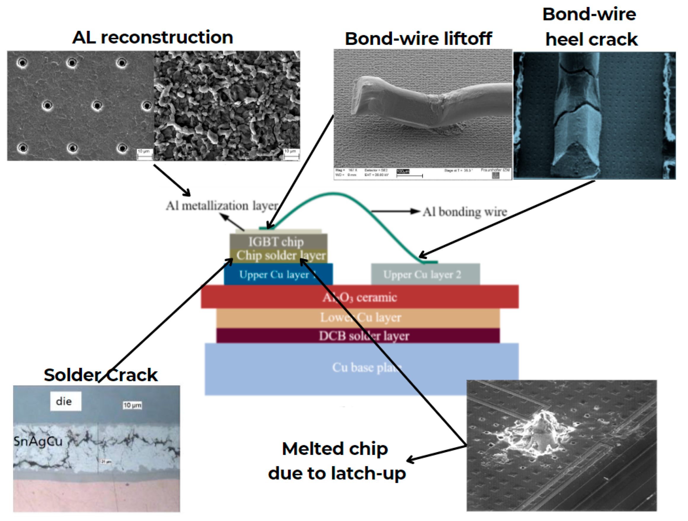
Figure 1. Failure mechanisms in IGBT modules.
Preprints 102723 g001
Figure 2. Groove profile giving y x ,   t
Preprints 102723 g002
Figure 3. A part of damped sinusoidal profile of the groove profile giving y x ,   t
Preprints 102723 g003
Figure 4. Comparison between the case of the alone diffusion and the combined evaporation and diffusion as a function of the distance from the symmetric axis of the groove.
Preprints 102723 g004
Figure 5. Evolution of the groove profile y x ,   t as a function of the distance x in the case of simultaneous effects of evaporation/condensation and diffusion for different values of m corresponding to a contact angle of the groove from θ = 5.7° to 45°.
Preprints 102723 g005
Figure 6. Variation of y   x 2 as a function of the distance x in the case of simultaneous effects of evaporation/condensation and diffusion for different values contact angle of the groove from θ = 5.7° to 45° (Case of cobalt metal).
Preprints 102723 g006
Figure 7. Dependence of the grain groove profile and its geometric characteristics on the boundary conditions in the case of evaporation/condensation and diffusion acting on polycrystalline thin films.
Preprints 102723 g007
Disclaimer/Publisher’s Note: The statements, opinions and data contained in all publications are solely those of the individual author(s) and contributor(s) and not of MDPI and/or the editor(s). MDPI and/or the editor(s) disclaim responsibility for any injury to people or property resulting from any ideas, methods, instructions or products referred to in the content.
Copyright: This open access article is published under a Creative Commons CC BY 4.0 license, which permit the free download, distribution, and reuse, provided that the author and preprint are cited in any reuse.
Prerpints.org logo

Preprints.org is a free preprint server supported by MDPI in Basel, Switzerland.

Subscribe

© 2024 MDPI (Basel, Switzerland) unless otherwise stated