1. Introduction
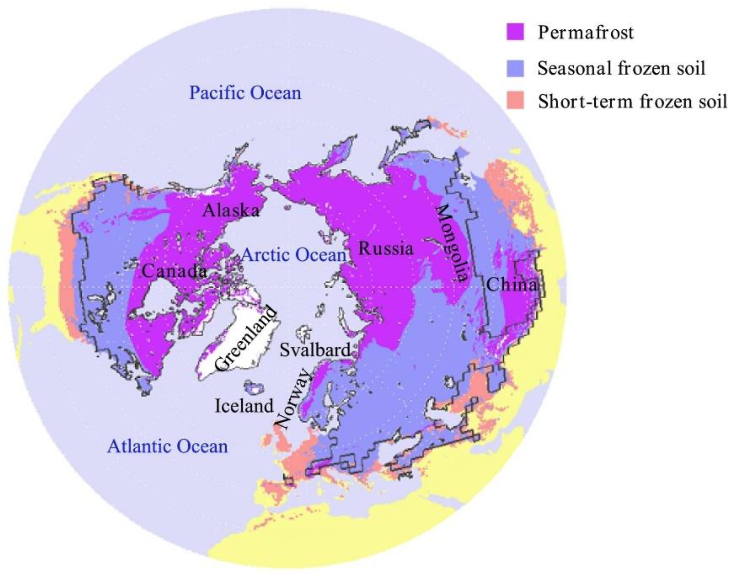
Permafrost is soil or rocks with the temperatures below 0 ℃ for at least two continuous years, and it covers about 23% ~ 25% of the land in the northern hemisphere (Figure 1), mainly in Russia, Canada, Alaska, Northeast and Qinghai Tibet Plateau (QTP) in China [
1]. In recent years, as a result of global warming, the average temperature in the permafrost regions has risen at about twice the rate of the rest of the world.[
2,
3]. Meanwhile, the construction of the highways will change the thermal stability of the permafrost and cause its degradation. Such as the Alaska Highway in the United States, the trans-Siberian Highway in Russia, the Dempster Highway in Canada and the Qinghai-Tibet Highway in China[
4,
5,
6,
7]. Therefore, it is a big challenge to build highway in permafrost region, under the dual role of the above.
Figure 2.
Distribution of permafrost in the northern hemisphere [
7] .
Figure 2.
Distribution of permafrost in the northern hemisphere [
7] .
For a long time, researchers have been working tirelessly to solve the problem of highway pavement damage in permafrost regions and have proposed many useful measures[
8,
9]. The Two-Phase Closed Thermosyphon Technique (TPCT) is one of the most efficient and cost-effective measures. The TPCT can prevent permafrost degradation to some extent and has been used in permafrost regions[
10,
11,
12,
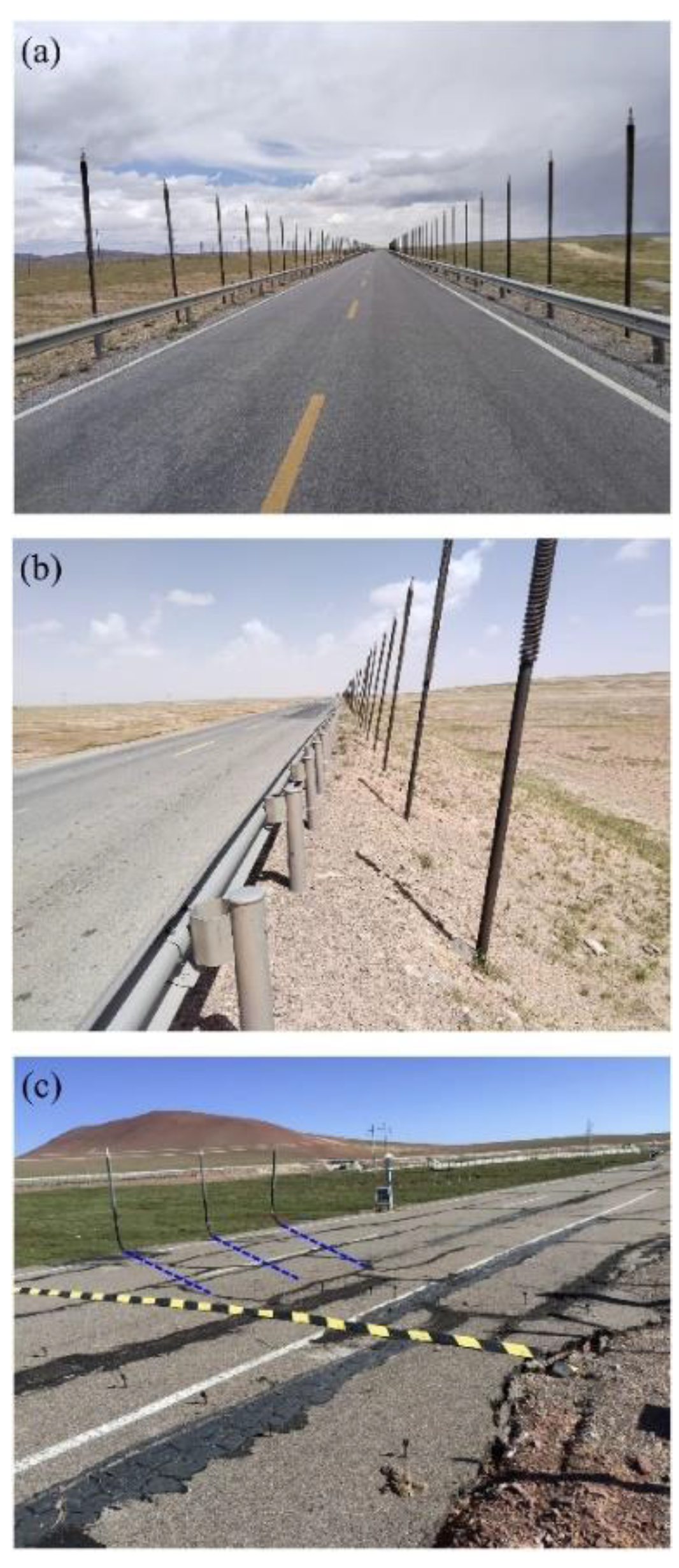
13]. However, damage still occurs. As shown in
Figure 2, the long cracks are still occurring. Therefore, it is necessary to summarize the working principles and factors of TPCT and then design new appropriate measures.
In view of the above, the paper is divided into two main sections: schematic analysis of the TPCT and applications. The first section includes: operating principles, factors affecting the operation of the TPCT. The second section lists the applications with special attention to the permafrost region, and the normal experimental and numerical approaches of applications of the TPCT.
2. Operating Principles of the TPCT
In the energy exchange systems, the two-phase closed thermosyphon (TPCT) is an efficient heat transfer device without any external energy [
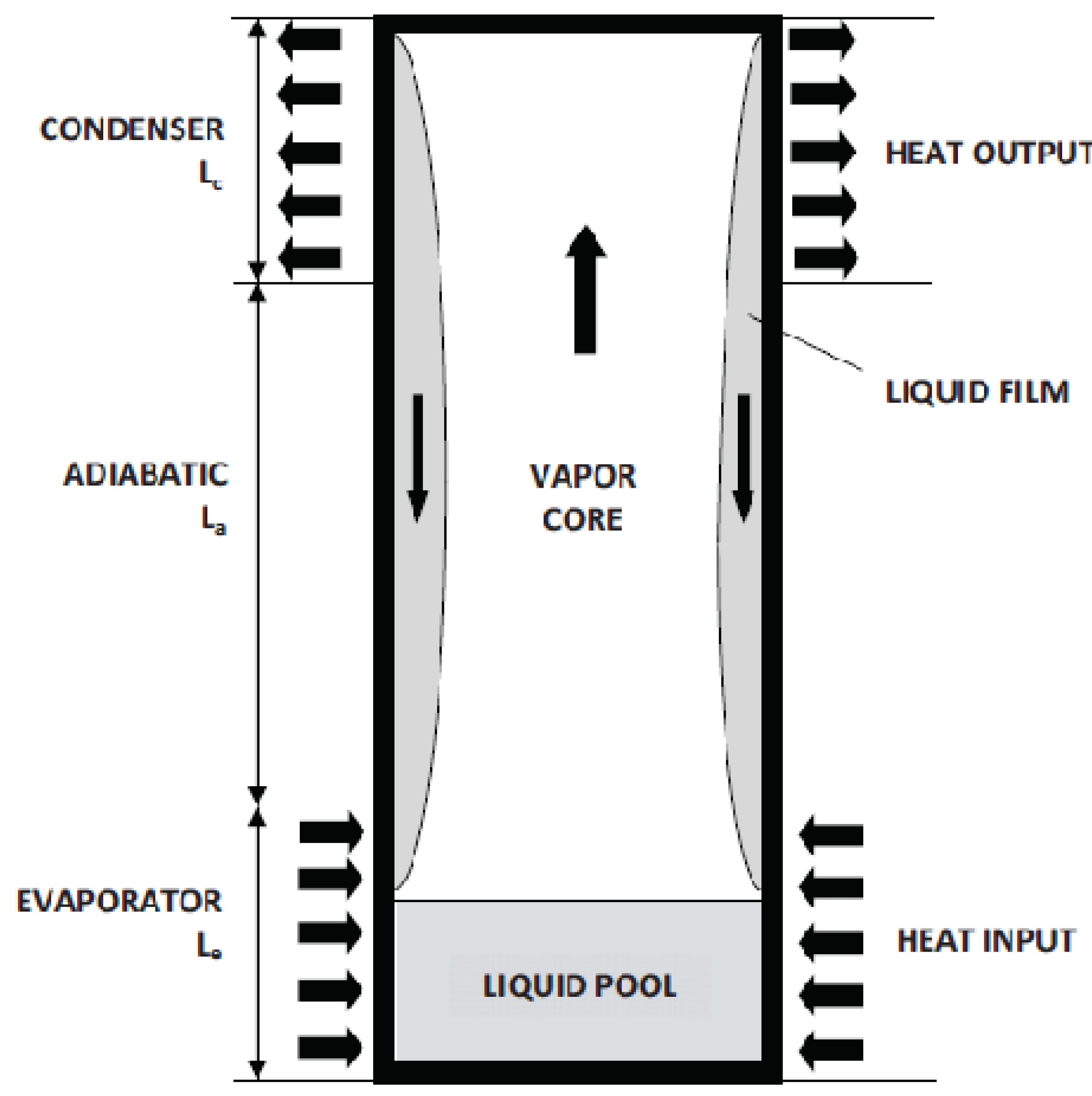
14]. Usually, a TPCT consists of three parts, including the evaporator section, the adiabatic section, and the condenser section [
15]. When it was applied in the highways in the permafrost region, the condenser section is exposed to the air and the evaporator section inserted into the embankments. The evaporator section is placed under the condenser section. It can effectively transport a large amount of heat energy along the tube wall with a small temperature difference between the condenser section and the evaporator section[
16,
17].
The detailed working principle is shown in
Figure 3. It mainly relies on the gas-liquid phase change of the internal work material and gravity reflux to transmit heat, the work material is accumulated at the bottom of the heat pipe, which can be liquid ammonia with low boiling point and environmental protection, etc. The evaporation section is in the lower half of the heat pipe, the condensation section is in the upper half of the heat pipe, and the adiabatic section is in the middle part. In the cold season, when the temperature of the evaporation section of the heat pipe is higher than the temperature of the condensing section, the heat pipe evaporation section of the workpiece is heated and evaporated into steam, under the action of differential pressure, the steam flows upward and rises to the condensing section, the exothermic condensation in the condensing section into a liquid, and then return to the evaporation section under the action of gravity to complete the cycle of work. Through the constant vaporization of the mass of heat absorption - condensation and exothermic, and thus a steady stream of heat pipe evaporation section near the heat transfer to the condensing section. As long as there is a temperature difference between the condensing section and the evaporating section, the heat pipe will continue this cycle of heat transfer[
10,
18].
3. Factors Affecting the Work of the TPCT
In permafrost TPCT engineering, the heat transfer performance of TPCT is the decisive factor to keep the subgrade permafrost in a frozen state. 1942, Gaugler put forward the principle of TPCT. 1965, Cotter put forward a more complete TPCT theory for the first time, which laid the foundation for the future research work of TPCT theory. Since then, many scholars have carried out a lot of research work on the heat transfer performance of TPCTs[
19,
20,
21]. It has been shown that the heat transfer performance of TPCT is mainly affected by the properties of the TPCT itself: the work fluid[
22,
23,
24,
25,
26], the liquid filling rate[
27,
28,
29,
30,
31] (the ratio of the work mass volume to the volume of the evaporating section of the TPCT), the length-to-diameter ratio [
14] (the ratio of the length of the evaporating section to the inner diameter of the TPCT), and the geometrical shape[
32,
33], as well as by the external environment: the angle of the inclination of the TPCT [
12,
34] , the ratio of the effective length of the TPCT [
17,
35] (the ratio of the effective lengths of evaporating and external environmental factors and wind speed [
36], etc. are also considered. The following is a selection of five important factors.
3.1. Working Fluid
Kanji Negishi et al. [
22] investigated the heat transfer coefficients of the heat pipe with different filling volumes and different work materials (water and ethanol) at different tilting angles of the heat pipe. It was found that the total heat transfer efficiency of the heat pipe with water as the work material was higher than that of the heat pipe with ethanol as the work material. Ma et al. [
23] investigated the effect of eight work materials on the heat transfer performance of heat pipe and found that the heat transfer performance of the heat pipe with R245fa/R152a as the work material was the best for the evaporation section at temperatures ranging from 35-95°C and the condensation section at temperatures ranging from 20°C. Engin Gedik [
24] found that the best heat transfer performance of heat pipes with three different media (water, ethanol and ethylene glycol) was achieved under different ambient conditions. From the above studies, it was found that the heat transfer performance of the heat pipe is not only affected by the working medium, but also by the ambient conditions.
3.2. Filling Ratio
The heat pipe filling rate is the ratio of the volume of the work mass inside the tube to the volume of the evaporating section of the heat pipe. Payakaruk et al. [
27] found that the heat pipe filling rate has no effect on the ratio of the heat flow at different angles and vertically. Wang and Ma [
28] found that the optimum angle of inclination of the heat pipe varies with the filling rate and ranges from about 20° to 50°.Emami et al. [
29] found the highest heat transfer efficiency for a heat pipe tilted at 35% for three types of aspect ratios at 60° for different filling rates and length to diameter ratio and different angles of inclination. Elmosbahi et al. [
30] found that the best heat transfer performance was achieved when the volume of methanol in the heat pipe was about 2/3 of the volume of the evaporation section.
In the perennial permafrost region, under negative temperature, the influence of liquid filling rate on the heat transfer performance of heat pipe is less studied. In the Alaskan pipeline [
37], when the heat pipe is not in operation, the height of liquid ammonia is controlled to be about 0.3-0.6 m. Zhang et al. [
14] investigated the heat transfer performance of a heat pipe with a liquid filling rate of 65% at low temperatures and found that the total thermal resistance was minimum at an inclination angle of 20°.
3.3. Inclined Angle
Pei et al. [
34] conducted indoor tests by modelling heat pipes with inclined angles of 50°, 70° and 90°. It was found that the ground temperature control efficiency of the heat pipe was the highest when the heat pipe was inclineded at 70°. Haynes et al. [
38] found that the heat transfer performance of the heat pipe increased with the increase of the inclined angle of the evaporation section at low temperatures, wind speeds of 0-5.2 m/s and heat pipe evaporation section angles of 0°-12°. Therefore, if the inclined angle of the heat pipe is used reasonably, the cooling performance of the heat pipe can be improved, and then the heat pipe spacing can be increased, the cost of the project can be reduced, or different inclined angles of the heat pipe can be adjusted to the sunny and shady slope effect.
3.4. Ambient Conditions
Haynes et al. [
39] found that the heat transfer performance of the heat pipe increased with the increase of wind speed at low temperatures, wind speeds ranging from 0 to 5.2 m/s, and the angle of the evaporating section of the heat pipe ranging from 0 to 12°. Zhang et al. [
40] found through indoor experiments that, when the heat pipe started to work, the efficiency of the heat pipe had a linear relationship with the temperature difference between the evaporating section and the condensing section. Therefore, the heat pipe works more efficiently under the lower temperature and higher wind speed.
3.5. Geometric Shape
In the permafrost region, depending on the shape of the TPCT, TPCTs can be approximately classified into straight TPCTs (straight or slant insert) [
41], L-shaped TPCTs [
32], horizontal TPCTs [
13], hairpin TPCTs [
42], and TMD-5 type [
43]. In China, USA and Canada, the evaporation section of the TPCT tends to be straight, with an adjustable tilt angle and without fins, while the condensing section is a straight pipe with fins. In Russia, a TPCT named TMD-5 has 12 vertical fins in the condensing section and aluminum Ω cross sections welded to the evaporating section to increase the cooling area and stiffness of the TPCT. Numerical calculations showed that after five years of operation, the thermal influence range of the TMD-5 was double that of a smooth round tube in the evaporation section. Subsequently, the cooling capacity of the TIP obtained by modifying the TMD-5 was increased by a factor of 1.6 compared to the TMD-5. In the range of applications, straight TPCTs are suitable for most projects, such as pile foundations, road foundations, and shallow tunnel sections [
7]; L-shaped TPCTs can be used for wide road foundations [
11]; horizontal TPCTs are mainly used for houses and airports [
26]; hairpin foundations are used in road foundation projects [
42]; and TMD-5 is mainly used for pile foundations in Russia [
43].
4. Applications of the TPCT
Currently, the TPCT have been widely used in the permafrost region to ensure the thermal stability of various types of foundations, such as: the highways, railways, tunnels, oil and gas pipelines, tower foundations, dams, airports, and other engineering. In this paper, we pay attention to the applications in the highways.
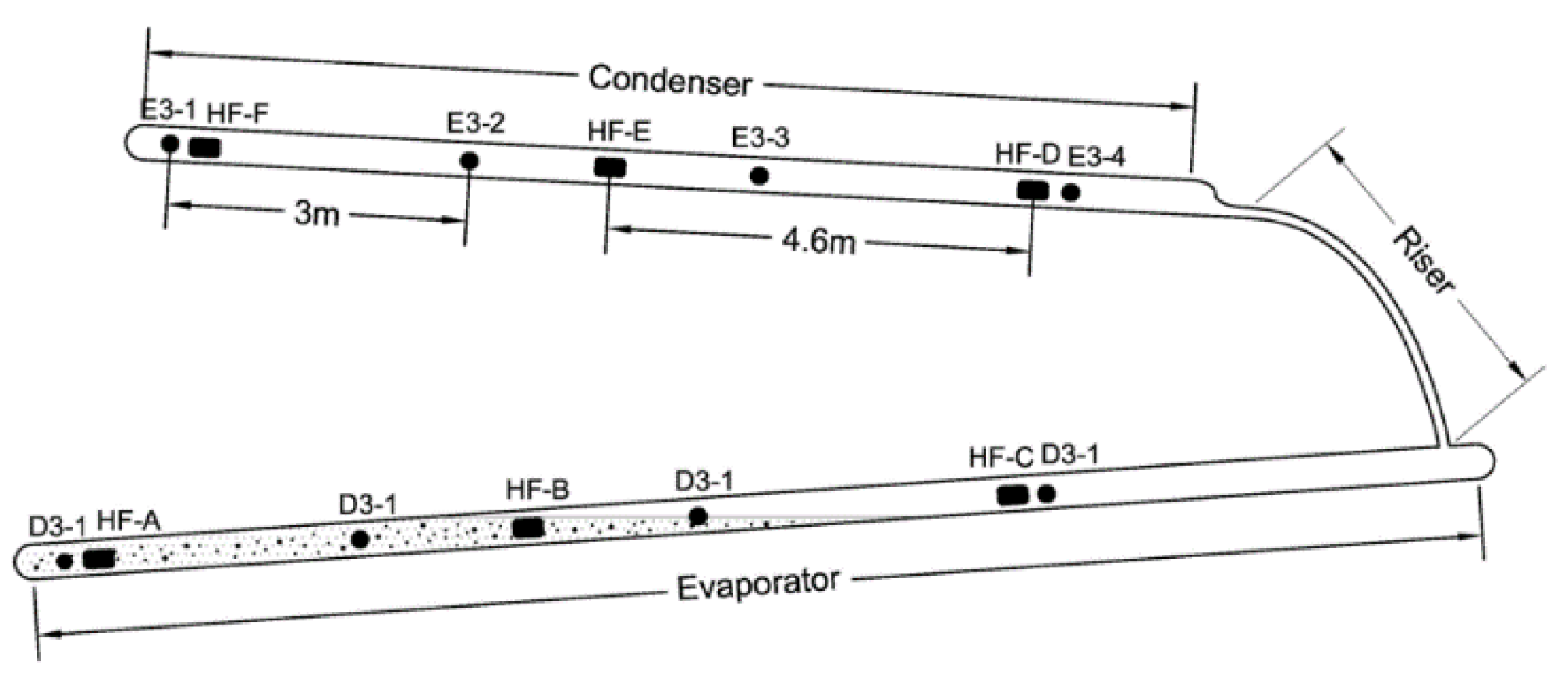
Xu et al. [
42] monitored an integrated temperature control system consisting of hairpin TPCTs (
Figure 4)and ventilated shoulders on the Alaska Highway, which is a high-temperature permafrost region that is particularly sensitive to temperature, and the construction of the highway would disrupt the original geothermal equilibrium of the ground air, which was found to be functioning well after one year of operation through the on-site monitoring data.
In China, TPCT was firstly applied to damaged highway culverts. Nearly 2,000 straight and diagonally inserted TPCTs were used to mitigate severe longitudinal cracks and melt subsidence in the Chumar River section of the Qinghai-Tibet Highway from 2002 to 2004 [
44]. Wu et al. [
45] analyzed the characteristics of the ground temperatures in the same horizontal and vertical directions based on the observations of the TPCT test section of the Qinghai-Tibet Highway from 2004 to 2012. Through indirect calculations, it was found that the TPCT transfers about 1200 MJ to 1500 MJ of heat per year, transferring more energy in the first few years, and gradually stabilizing the heat transferred by the TPCT over time. Yu et al [
46] found that the TPCT could effectively cool the submerged multiyear permafrost of the roadbed, and that the optimal cooling effect of the TPCT was located in the middle of its evaporation section. Jinlong et al. [
44] analyzed the ground temperature characteristics, temperature field morphology and freezing and thawing process of TPCT roadbed based on nearly 11 years of field monitoring data of the TPCT roadbed test project on Qinghai-Tibet Highway, estimated the horizontal heat gain and loss condition near the TPCT under the influence of the roadbed's yin and yang slope effect, and concluded that the long term cooling effect of the bi-lateral TPCT roadbed was stronger than that of the unilateral TPCT roadbed, and that the diagonally-inserted TPCT roadbed was stronger than that of the straight-inserted TPCT roadbed.
High-grade highways have the structural characteristics of "wide, thick and black" and strong heat absorption, heat storage and heat gathering effects, which pose a greater threat to the stability of perennial permafrost roadbeds. Many scholars have carried out a series of research on the thermal stability of high-grade wide roadbeds [
7]. Lai et al. [
32] and Dong Yuanhong et al. [
47] designed an L-shaped TPCT-block gravel berm-insulated panel composite roadbed in order to achieve the purpose of maintaining the thermal stability of a wide high-grade highway in a permafrost zone while protecting the underlying permafrost. In order to verify the cooling effect of the new TPCT composite roadbed, an indoor model test was carried out, and the test results preliminarily proved the effective cooling ability of this roadbed, and it was found that the air temperature remained negative in most parts of the roadbed after the end of the positive temperature period, remaining around -0.4°C. Zhang et al. [
33] conducted a wide test roadbed in the Beiluhe area of the Qinghai-Tibetan Plateau monitoring and comparatively analyzed an L-shaped TPCT-insulation board-block gravel berm composite roadbed and an unprotected roadbed as a control. The longitudinal length of the L-shaped TPCT-insulation board-block gravel berm composite roadbed was 16.5m, the top surface width was 15.9m, and the asphalt pavement width was 11.5m, with four lanes in both directions. After about 4 years of monitoring, compared with the unprotected roadbed with no protection measures and roughly the same direction, it is obviously found that the L-shaped TPCT-insulation board-block gravel berm composite roadbed not only solves the sunny and shady slope effect of the unprotected roadbed, but also lifts up the upper limit of the perennial permafrost under the roadbed, effectively cools down the underlying perennial permafrost, and enhances the thermal stability of the wide roadbed in the perennial permafrost area. In addition, the Gonghe to Yushu Expressway in Qinghai Province is the world's first high-altitude and high-cold permafrost highway, and in order to protect the stability of the roadbed in the perennial permafrost development of the Chalaping area, the first phase of the project used nearly 4,000 TPCTs [
8].
However, the application of TPCT roadbed in highway still has different degrees of problems. Wang et al. [
44] investigated the Qinghai-Tibet Highway and found that 30.8km of heat pipe roadbed had a disease rate of 35%, of which 10% was serious disease. The main diseases of heat pipe roadbed are longitudinal cracks, and there are also corrugated roadbed, transverse cracks and other diseases. The main cause of the diseases is the uneven distribution of mechanical properties of the roadbed caused by the uneven temperature field.
5. Performance Evaluation of the TPCT
To further evaluate the work performance of the TPCT, numerical simulation is an efficient way to predict future changes in highway embankments with TPCTs in permafrost regions. According to the angle of inclination, we classify TPCTs into three types: vertical TPCTs, L-shaped TPCTs and horizontal TPCTs.
5.1. Vertical TPCTs
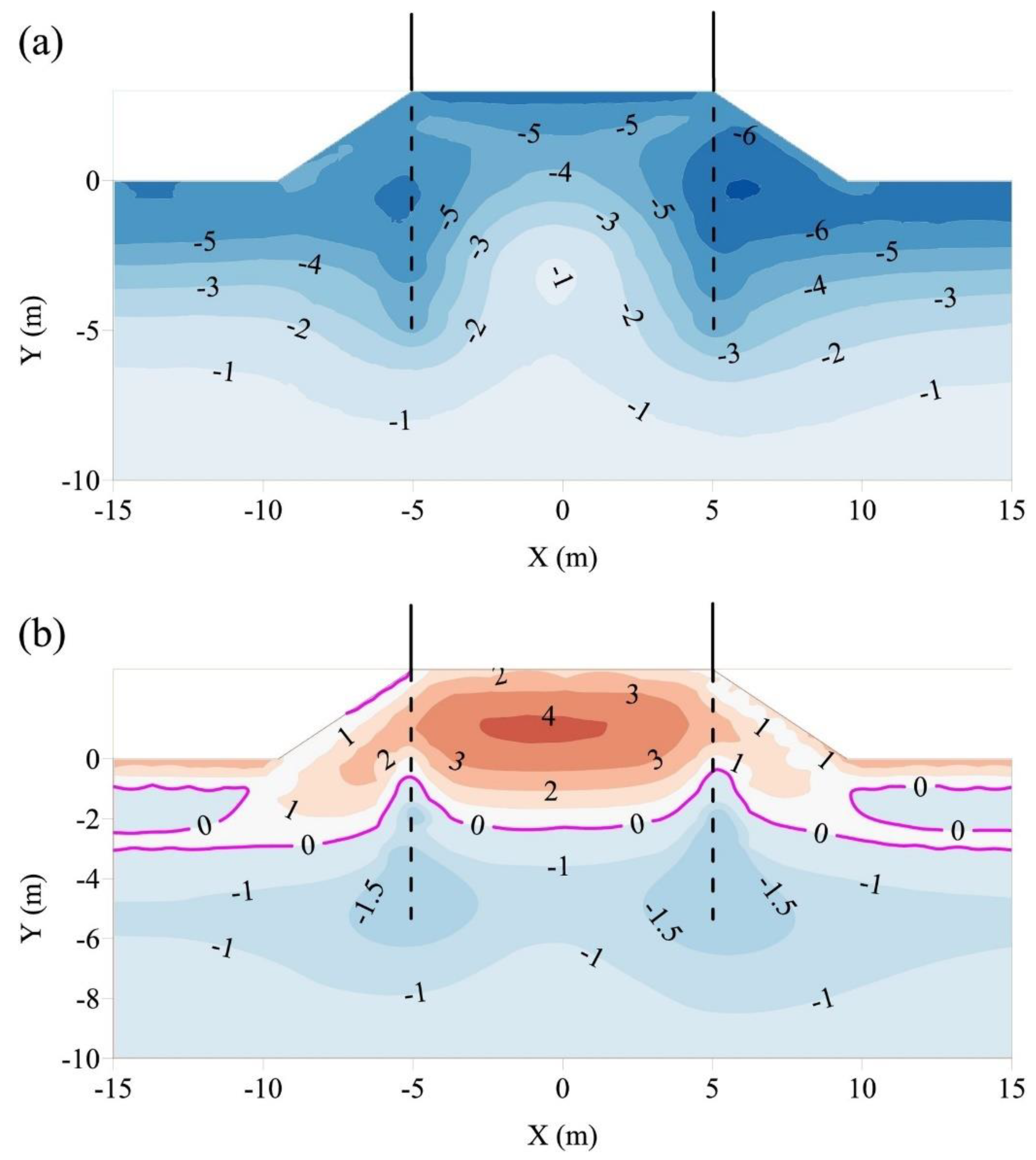
The vertical TPCTs is the most common technology used in the permafrost regions. Soil temperature distributions of a highway’s roadbed with vertical TPCTs in winter and summer are shown in
Figure 5. It can be seen that the permafrost table was significantly raised in the vicinity of the TPCTs. The soils around the TPCTs were also colder than those away from the TPCTs. Since soil pore water can migrate from unfrozen soil to freezing soil under the influence of the temperature gradient, a lot of water was collected around the TPCTs. As a result, frost heave occurs around the TPCTs in winter, which can easily generate longitudinal cracks closed to the TPCTs. In addition, in summer the permafrost table around the TPCTs was convex, but the permafrost table under the center of the carriageway was concave. Since the compressive strength of the soil is much greater than the tensile strength [
46], the unfrozen soil layer around the roadbed shoulder may have a tendency to slide along the convex permafrost table, and the unfrozen soil layer at the roadbed centerline may have a tendency to slide down along the concave permafrost table. As a result, cracking was more likely to occur at the shoulder of the road.
5.2. L-Shaped TPCTs
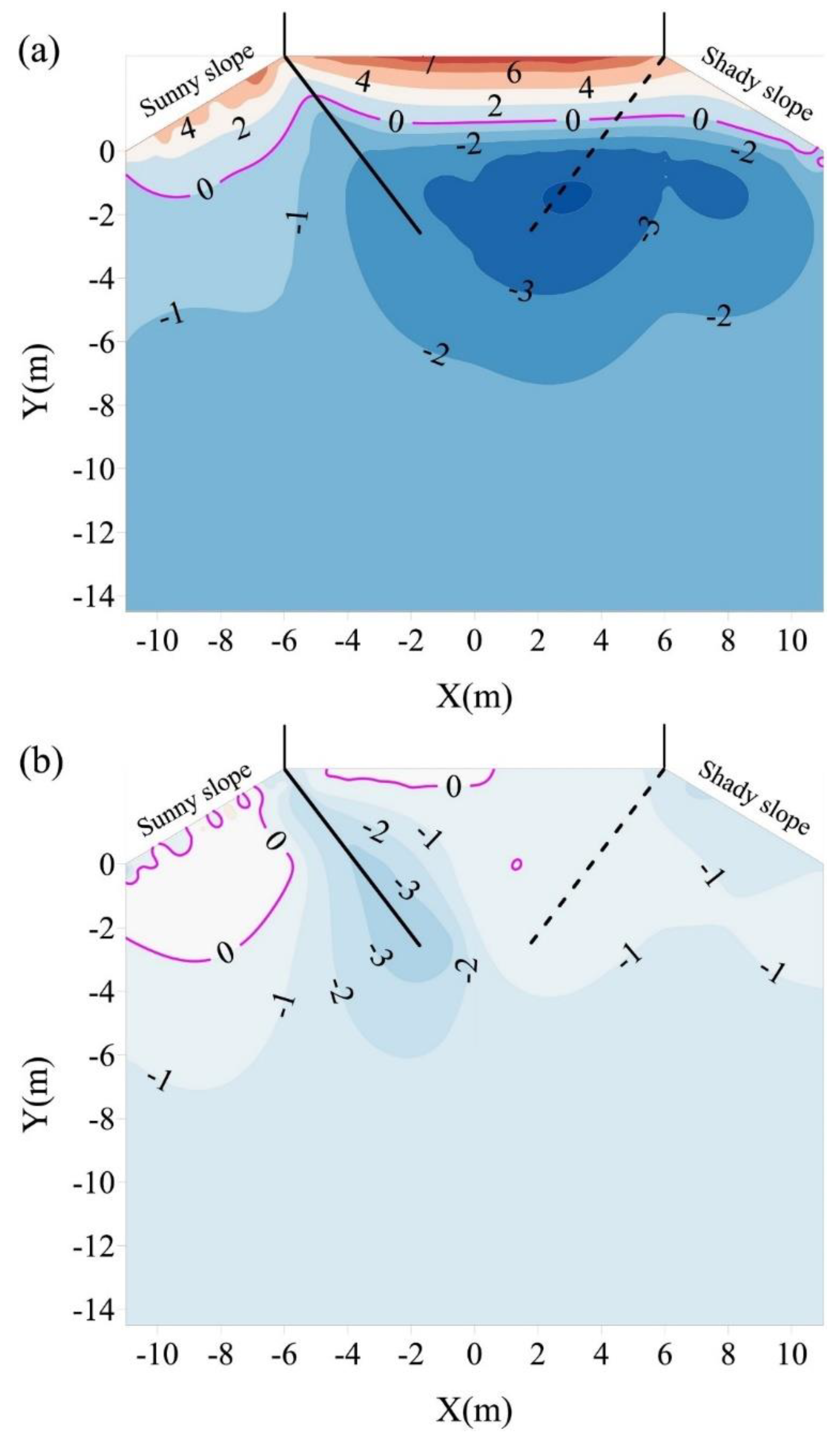
Figure 6 displays the ground temperature distributions of a roadbed with L-shaped TPCTs during summer and winter. The TPCTs were placed along the sunny and shady slope shoulders at a 45-degree angle and a staggered interval of 1.5 meters on both sides of the roadbed. The results indicate that the L-shaped TPCTs can cool the permafrost under the roadbed centerline and shady slope, causing the permafrost table to elevate. However, the cooling system is ineffective in cooling the permafrost below the sunny slope, resulting in fluctuations in the freezing-thawing interface under the roadbed. During summer, the topsoil layers of the roadbed thawed, and the permafrost table beneath the sunny slope was deeper than that beneath the roadbed centerline and shady slope, as shown in
Figure 6. This indicates that the permafrost degradation beneath the sunny slope is more severe than that beneath the roadbed centerline and shady slope. A convex isotherm is clearly visible below the sunny slope. It is important to note that frozen soil is much stiffer than unfrozen soil and has a lower tensile strength than its compressive strength [
48]. Therefore, the soil on the sunny slope may slide downward along the convex isotherm, which can lead to crack formation on the sunny side. During winter, the L-shaped TPCTs have a cooling effect on the ground temperature, resulting in an elliptical distribution that is lower around the TPCTs than away from them (see
Figure 6). This causes excess water to migrate towards the sunny slope and accumulate around the TPCTs, leading to frost heave and promoting crack growth. It is important to note that this phenomenon occurs only around the L-shaped TPCTs.
5.3. Horizontal TPCTs
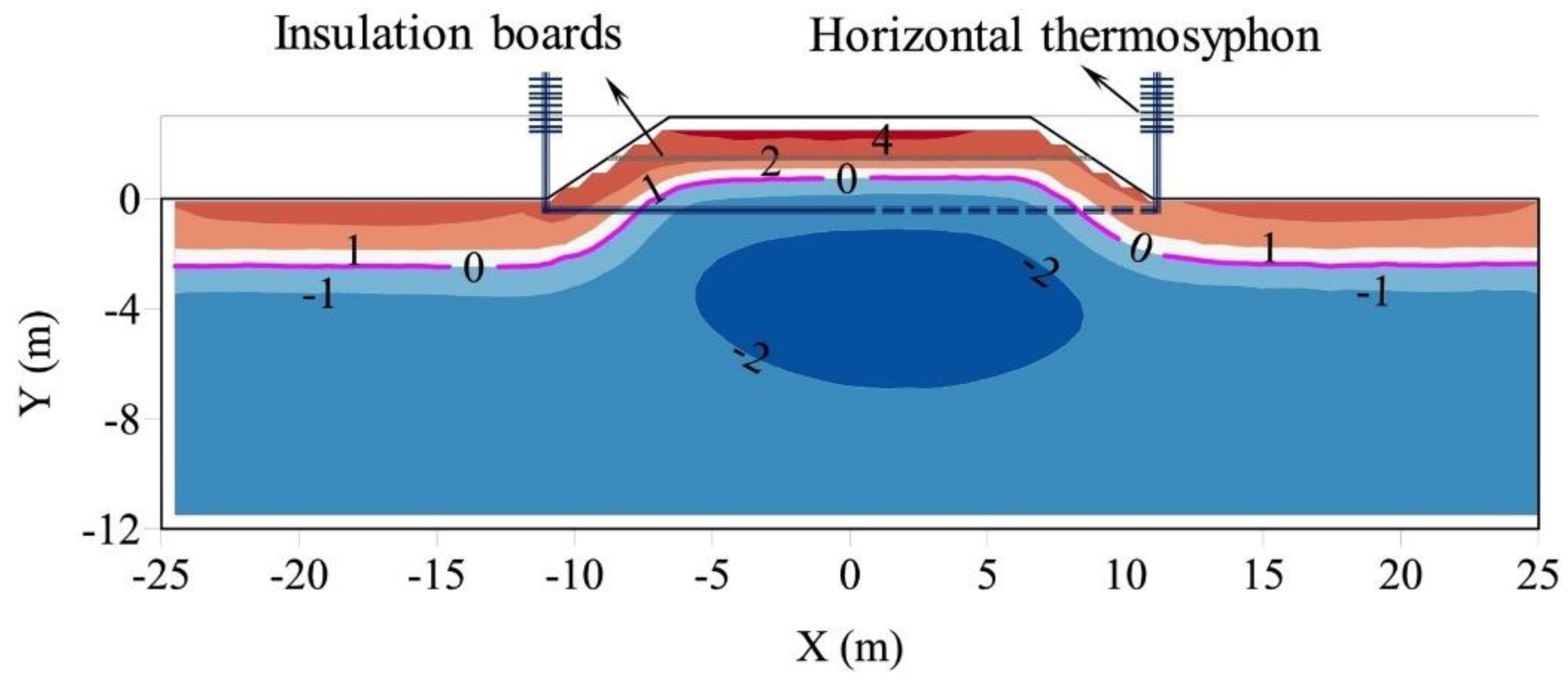
To solve the problem caused by the TPCTs above, the horizontal TPCTs were proposed with the insulation boards which can store the ‘cold energy’ brought by the TPCTs [
49]. To achieve an even and lamellar temperature distribution, a horizontal thermosyphon was designed [
50]. The ground temperature distribution of the roadbed in its 20th year of service is shown in
Figure 7. It is evident that a frozen layer with a temperature lower than -2.0°C appears beneath the roadbed and expands to the slope foot. The soil temperature is undergoing a balanced cooling process, as indicated by the even and lamellar distribution of temperature isotherms with large vertical spacing. The ground temperature distribution of the new roadbed is symmetrical along the centerline, making it suitable for use in permafrost regions and meeting the required geotemperature distribution criteria. The ground temperature distribution of the new roadbed is symmetrical along the centerline, making it suitable for use in permafrost regions and meeting the required geotemperature distribution criteria. This has been confirmed by laboratory tests [
13].
6. Limitations of the TPCT
The limitations of the TPCT includes its own limitations and problems that arise in applications.
First section: Although TPCTs are effective transfer devices, there are some limits, including viscous, sonic, dryout, boiling, flooding, and geyser boiling.
- (1)
The sonic limits are mentioned in theory, but never observed.
- (2)
The viscous limit is that the pressure difference is smaller than the viscous force, the vapor cannot move and the viscous limit reach [
52].
- (3)
The dryout limit occurs at small working fluid. For the continuous circulation of the two phases, there are a minimum mass of working fluid. When the available mass is smaller than the minimum, the bottom of the evaporator will dryout [
53,
54].
- (4)
The boiling limit: when it occurs, a transition from nucleate boiling to film boiling, which will greatly increase the risk of the TPCT damage.
- (5)
The flooding limit: the latent heat of vaporization of the working fluid is necessary in controlling the flooding limit. Once the axial heat fluxes are higher than the radial heat fluxes, the upward vapor will prevent the liquid from going back to the evaporator. Meanwhile, the evaporator will dryout [
55,
56].
- (6)
The geyser boiling limit: this is an unstable phenomenon [
57]. Khazaee et al. [
58] examined geyser boiling in two TPCTs with different diameters (15 and 25 mm) and a length of 1000 mm. The results of the experiment showed that the period of geyser boiling decreased as the heat load and aspect ratio increased.
Considering the limit above, the use of TPCTs is more important to pay attention to the conditions of its use, choose the appropriate optimal design ratio to meet the higher engineering needs.
Second section: the TPCTs have been successfully in the highways, it can significantly cool the roadbeds and enhance the permafrost thermal stability. However, there are several limits listed below.
- (1)
The cooling range of the TPCTs is limited, and the effective cooling range is about 2.4 m [
59].
- (2)
The asymmetric geotemperature distribution under the roadbeds caused by the TPCTs can affect their stability [
13]. As shown in
Figure 6, the area is near the TPCTs where the temperature is lower than the rest area which causes the frost heaven in winter. Then in summer, the thawed depth is uneven which causes the sliding down at shoulder.
- (3)
The installation holes around the TPCTs were uncompacted [
7]. They will settle after the freeze-thaw cycle. The water from the rain will fill these holes and accelerate the damage process of the roadbeds.
Thus, it is necessary to optimize the better performance structure to meet these needs.
7. Future Development of TPCTs
Lower heat loss, higher transfer efficiency, longer work time and less economic cost are the objectives of the evolution of TPCTs. With the global warming and the requirement improving for high-efficiency structures, expectations for stable TPCTs structure are increasing. Based on evaluation of cooling performance for the TPCTs structure, the following research directions are proposed:
Utilization of latent heat of the working fluid: TPCTs cooling generally uses liquid convection heat transfer. Combining the two-phase heat transfer of the working fluid with utilizing the latent of it, the cooling capacity can be improved.
Optimization of the design of the TPCT: According to the needs in the engineering, the inner channel design of the TPCT should be optimized to reduce flow resistance and ensure the uniformity of roadbeds temperature distributions.
Establishment of the ventilation ducts: The ventilation ducts can improve the convection heat transfer efficiency, then improve the cooling performance of the TPCT roadbeds. An external air system can also be installed.
Installation the solar generator: Improvement of the TPCT with the addition of a solar generator, which can make it to use solar energy to operate the TPCT for a long time.
Update of the materials: Currently, the material of the TPCT is stainless steel. Improve the corrosion and frost resistance of the material, which can be used for a longer period and reduce the cost.
8. Summary
As the construction of the highways in permafrost regions, the requirements for the stability have been pushed to a new level. The TPCT as an efficient transfer device have been applied widely to cool the roadbeds. Effective cooling performance of the TPCT is essential to decrease deformation and the error of the roadbeds. In this paper, the summary of the advance and application of the TPCT has been done through the following work.
The detailed introduction of the operation of the TPCT is presented. The factors of the TPCT mainly include working fluid, inclined angle, filling ratio, ambient conditions, and Geometric shape. Recent developments in each of these factors are also discussed.
The application of the TPCT mainly in the highways in the permafrost region are presented. The numerical performance of the different TPCT structure is also discussed. The vertical TPCT are the most common technique but may cause the crakes in the pavement. The L-shaped TPCT can cool the center temperature well however the sunny and shady slope influence will be increased. The horizontal TPCT can well meet the required geotemperature distribution criteria.
The limit of the TPCT has been listed. Firstly, for the TPCT itself, there are viscous, sonic, dryout, boiling, flooding, and geyser boiling limit. Secondly, for the engineering application, the limit includes the cooling range, asymmetric geotemperature distribution and the installation holes.
Future development of TPCT is predicted. Utilization of latent heat of the working fluid, Optimization of the design of the TPCT, Establishment of the ventilation ducts, Installation the solar generator and Update of the materials can be mainly considered.
Author Contributions
Conceptualization, S.D.; formal analysis, S.D.; writing—original draft preparation, S.D.; writing—review and editing, Z.Y.; visualization, S.D. All authors have read and agreed to the published version of the manuscript.
Institutional Review Board Statement
Not applicable.
Informed Consent Statement
Not applicable.
Data Availability Statement
The data is available from the corresponding author (Shuai Du; S.D.) on reasonable request.
Acknowledgments
The authors are thankful for Northwest Institute of Eco-Environment and Resources, Chinese Academy of Sciences, University of Chinese Academy of Sciences for the support.
Conflicts of Interest
The authors declare no conflict of interest.
References
- Cao, Z.; Nan, Z.; Hu, J.; Chen, Y.; Zhang, Y. A New 2010 Permafrost Distribution Map over the Qinghai–Tibet Plateau Based on Subregion Survey Maps: A Benchmark for Regional Permafrost Modeling. Earth System Science Data 2023, 15, 3905–3930. [Google Scholar] [CrossRef]
- Hjort, J.; Karjalainen, O.; Aalto, J.; Westermann, S.; Romanovsky, V.E.; Nelson, F.E.; Etzelmüller, B.; Luoto, M. Degrading Permafrost Puts Arctic Infrastructure at Risk by Mid-Century. Nat Commun 2018, 9, 5147. [Google Scholar] [CrossRef] [PubMed]
- Hjort, J.; Streletskiy, D.; Doré, G.; Wu, Q.; Bjella, K.; Luoto, M. Impacts of Permafrost Degradation on Infrastructure. Nat Rev Earth Environ 2022, 3, 24–38. [Google Scholar] [CrossRef]
- Kong, X.; Doré, G.; Calmels, F.; Lemieux, C. Field and Numerical Studies on the Thermal Performance of Air Convection Embankments to Protect Side Slopes in Permafrost Environments. Cold Regions Science and Technology 2021, 189, 103325. [Google Scholar] [CrossRef]
- Kondratiev, V.G. Main Geotechnical Problems of Railways and Roads in Kriolitozone and Their Solutions. Procedia Engineering 2017, 189, 702–709. [Google Scholar] [CrossRef]
- Yang, S.; Zhang, M.; Bi, J.; Pei, W.; Bai, R. Optimizing Embankment Structures in a Snowy Permafrost Region of the Pan-Arctic Based on a Coupled Numerical Model. Transportation Geotechnics 2023, 38, 100889. [Google Scholar] [CrossRef]
- Ma, Q.; Lan, T.; Lai, Y.; Luo, X.; He, P. Application of the Cooling Measures in the Highway Roadbed in Permafrost Regions of the Qinghai-Tibet Plateau. Cold Regions Science and Technology 2024, 221, 104177. [Google Scholar] [CrossRef]
- Wu, Q.; Ma, W.; Lai, Y.; Cheng, G. Permafrost Degradation Threatening the Qinghai−Xizang Railway. Engineering 2024, S2095809924001292. [Google Scholar] [CrossRef]
- Lai, Y.; Zhang, S.; Zhang, L.; Xiao, J. Adjusting Temperature Distribution under the South and North Slopes of Embankment in Permafrost Regions by the Ripped-Rock Revetment. Cold Regions Science and Technology 2004, 39, 67–79. [Google Scholar] [CrossRef]
- Li, S.; Pei, W.; Wang, C.; Lai, Y.; Shi, L. Thermo-Seismic Performances of a Unilateral Two-Phase Closed Thermosyphon (TPCT) Embankment in Earthquake-Prone Permafrost Regions. Transportation Geotechnics 2021, 27, 100456. [Google Scholar] [CrossRef]
- Pei, W.; Zhang, M.; Lai, Y.; Yan, Z.; Li, S. Evaluation of the Ground Heat Control Capacity of a Novel Air-L-Shaped TPCT-Ground (ALTG) Cooling System in Cold Regions. Energy 2019, 179, 655–668. [Google Scholar] [CrossRef]
- Qinguo, M.; Xiaoxiao, L.; Jianqiang, G.; Tianli, L. Evaluation of the Application Effect of the Inclined TPCTs on an Embankment with the Shady-Sunny Slope Effect in Permafrost Regions. Cold Regions Science and Technology 2023, 213, 103936. [Google Scholar] [CrossRef]
- Pei, W.; Zhang, M.; Lai, Y.; Zhang, X.; Luo, T. A Self-Adaption Horizontal Thermosyphon Technology in Uneven Thermal Control of Roadway Embankments in Sub-Arctic Permafrost Regions. Transportation Geotechnics 2022, 33, 100714. [Google Scholar] [CrossRef]
- Zhang, M.; Lai, Y.; Dong, Y.; Jin, L.; Pei, W.; Harbor, J. Laboratory Investigation of the Heat Transfer Characteristics of a Two-Phase Closed Thermosyphon. Cold Regions Science and Technology 2013, 95, 67–73. [Google Scholar] [CrossRef]
- Yan, Z.; Zhang, M.; Lai, Y.; Pei, W.; Luo, T.; Yu, F.; Yang, S. Countermeasures Combined with Thermosyphons against the Thermal Instability of High-Grade Highways in Permafrost Regions. International Journal of Heat and Mass Transfer 2020, 153, 119047. [Google Scholar] [CrossRef]
- Anand, R.S.; Jawahar, C.P.; Solomon, A.B.; Bellos, E. A Review of Experimental Studies on Cylindrical Two-Phase Closed Thermosyphon Using Refrigerant for Low-Temperature Applications. International Journal of Refrigeration 2020, 120, 296–313. [Google Scholar] [CrossRef]
- Abreu, S.L.; Colle, S. An Experimental Study of Two-Phase Closed Thermosyphons for Compact Solar Domestic Hot-Water Systems. Solar Energy 2004, 76, 141–145. [Google Scholar] [CrossRef]
- Chen, L.; Yu, W.; Lu, Y.; Liu, W. Numerical Simulation on the Performance of Thermosyphon Adopted to Mitigate Thaw Settlement of Embankment in Sandy Permafrost Zone. Applied Thermal Engineering 2018, 128, 1624–1633. [Google Scholar] [CrossRef]
- Shabgard, H.; Allen, M.J.; Sharifi, N.; Benn, S.P.; Faghri, A.; Bergman, T.L. Heat Pipe Heat Exchangers and Heat Sinks: Opportunities, Challenges, Applications, Analysis, and State of the Art. International Journal of Heat and Mass Transfer 2015, 89, 138–158. [Google Scholar] [CrossRef]
- Jouhara, H.; Chauhan, A.; Nannou, T.; Almahmoud, S.; Delpech, B.; Wrobel, L.C. Heat Pipe Based Systems - Advances and Applications. Energy 2017, 128, 729–754. [Google Scholar] [CrossRef]
- Jafari, D.; Franco, A.; Filippeschi, S.; Di Marco, P. Two-Phase Closed Thermosyphons: A Review of Studies and Solar Applications. Renewable and Sustainable Energy Reviews 2016, 53, 575–593. [Google Scholar] [CrossRef]
- Negishi, K.; Sawada, T. Heat Transfer Performance of an Inclined Two-Phase Closed Thermosyphon. International Journal of Heat and Mass Transfer 1983, 26, 1207–1213. [Google Scholar] [CrossRef]
- Ma, L.; Shang, L.; Zhong, D.; Ji, Z. Experimental Investigation of a Two-Phase Closed Thermosyphon Charged with Hydrocarbon and Freon Refrigerants. Applied Energy 2017, 207, 665–673. [Google Scholar] [CrossRef]
- Gedik, E. Experimental Investigation of the Thermal Performance of a Two-Phase Closed Thermosyphon at Different Operating Conditions. Energy and Buildings 2016, 127, 1096–1107. [Google Scholar] [CrossRef]
- Drage, J.; Brooks, H. Performance of a Thermopile (Long Thermopile) Foundation—50 Years Later. In Proceedings of the Cold Regions Engineering 2012; American Society of Civil Engineers: Quebec City, Canada, August 17 2012; pp. 358–368.
- Yarmak, E. Permafrost Foundations Thermally Stabilized Using Thermosyphons. In Proceedings of the All Days; OTC: Copenhagen, Denmark, March 23 2015; p. OTC-25500-MS. [Google Scholar]
- Payakaruk, T.; Terdtoon, P.; Ritthidech, S. Correlations to Predict Heat Transfer Characteristics of an Inclined Closed Two-Phase Thermosyphon at Normal Operating Conditions. Applied Thermal Engineering 2000, 20, 781–790. [Google Scholar] [CrossRef]
- Wang, J.C.Y.; Ma, Y. Condensation Heat Transfer Inside Vertical and Inclined Thermosyphons. Journal of Heat Transfer 1991, 113, 777–780. [Google Scholar] [CrossRef]
- Emami, M.R.S.; Noie, S.H.; Khoshnoodi, M. EFFECT OF ASPECT RATIO AND FILLING RATIO ON THERMAL PERFORMANCE OF AN INCLINED TWO-PHASE CLOSED THERMOSYPHON. 2008, 32.
- Elmosbahi, M.S.; Dahmouni, A.W.; Kerkeni, C.; Guizani, A.A.; Ben Nasrallah, S. An Experimental Investigation on the Gravity Assisted Solar Heat Pipe under the Climatic Conditions of Tunisia. Energy Conversion and Management 2012, 64, 594–605. [Google Scholar] [CrossRef]
- Seo, D.; Seo, J.H.; Shim, J.; Nam, Y.; Lee, J. Effect of Marangoni Condensation on the Heat Transfer Performance of Two-Phase Closed Thermosyphons. International Journal of Heat and Mass Transfer 2023, 202, 123669. [Google Scholar] [CrossRef]
- Lai, Y.; Guo, H.; Dong, Y. Laboratory Investigation on the Cooling Effect of the Embankment with L-Shaped Thermosyphon and Crushed-Rock Revetment in Permafrost Regions. Cold Regions Science and Technology 2009, 58, 143–150. [Google Scholar] [CrossRef]
- Zhang, M.; Lai, Y.; Wu, Q.; Yu, Q.; Zhao, T.; Pei, W.; Zhang, J. A Full-Scale Field Experiment to Evaluate the Cooling Performance of a Novel Composite Embankment in Permafrost Regions. International Journal of Heat and Mass Transfer 2016, 95, 1047–1056. [Google Scholar] [CrossRef]
- Pei, W.; Zhang, M.; Li, S.; Lai, Y.; Dong, Y.; Jin, L. Laboratory Investigation of the Efficiency Optimization of an Inclined Two-Phase Closed Thermosyphon in Ambient Cool Energy Utilization. Renewable Energy 2019, 133, 1178–1187. [Google Scholar] [CrossRef]
- Zhang, M.; Yan, Z.; Pei, W.; Lai, Y.; Qin, Y.; Yu, F. Experimental Study on the Startup and Heat Transfer Behaviors of a Two-Phase Closed Thermosyphon at Subzero Temperatures. International Journal of Heat and Mass Transfer 2022, 190, 122283. [Google Scholar] [CrossRef]
- Gou, X.; Li, G.; Zhang, R.; Jian, C.; Zhang, Q.; Li, B.; Dong, Q. Critical and Optimal Inclination Angles of Two-Phase Closed Thermosyphon under Different Operating Conditions. International Journal of Heat and Mass Transfer 2021, 177, 121540. [Google Scholar] [CrossRef]
- Wu, H.; Liu, J.; Zhang, X. Feasibility Study on Use of Cellular Concrete for Air Convection Embankment on Permafrost Foundations in Fairbanks, Alaska. Transportation Geotechnics 2020, 22, 100317. [Google Scholar] [CrossRef]
- Haynes, F.D.; Zarling, J.P. Thermosyphons and Foundation Design in Cold Regions. Cold Regions Science and Technology 1988, 15, 251–259. [Google Scholar] [CrossRef]
- Haynes, F.D.; Zarling, J.P.; Gooch, G.E. Performance of a Thermosyphon with a 37-Meter-Long, Horizontal Evaporator. Cold Regions Science and Technology 1992, 20, 261–269. [Google Scholar] [CrossRef]
- Zhang, M.; Lai, Y.; Pei, W.; Jin, L. Effect of Inclination Angle on the Heat Transfer Performance of a Two-Phase Closed Thermosyphon under Low-Temperature Conditions. J. Cold Reg. Eng. 2014, 28, 04014007. [Google Scholar] [CrossRef]
- Ma, W.; Wen, Z.; Sheng, Y.; Wu, Q.; Wang, D.; Feng, W. Remedying Embankment Thaw Settlement in a Warm Permafrost Region with Thermosyphons and Crushed Rock Revetment. Can. Geotech. J. 2012, 49, 1005–1014. [Google Scholar] [CrossRef]
- Xu, J.; Goering, D.J. Experimental Validation of Passive Permafrost Cooling Systems. Cold Regions Science and Technology 2008, 53, 283–297. [Google Scholar] [CrossRef]
- Bayasan, R.M.; Korotchenko, A.G.; Volkov, N.G.; Pustovoit, G.P.; Lobanov, A.D. Use of Two-Phase Heat Pipes with the Enlarged Heat-Exchange Surface for Thermal Stabilization of Permafrost Soils at the Bases of Structures. Applied Thermal Engineering 2008, 28, 274–277. [Google Scholar] [CrossRef]
- Wang, S.; Jin, L.; Peng, H.; Chen, J.; Mu, K. Damage Analysis of the Characteristics and Development Process of Thermosyphon Embankment along the Qinghai-Tibet Highway. Cold Regions Science and Technology 2017, 142, 118–131. [Google Scholar] [CrossRef]
- Wu, D.; Jin, L.; Peng, J.; Dong, Y.; Liu, Z. The Thermal Budget Evaluation of the Two-Phase Closed Thermosyphon Embankment of the Qinghai–Tibet Highway in Permafrost Regions. Cold Regions Science and Technology 2014, 103, 115–122. [Google Scholar] [CrossRef]
- Yu, F.; Zhang, M.; Lai, Y.; Liu, Y.; Qi, J.; Yao, X. Crack Formation of a Highway Embankment Installed with Two-Phase Closed Thermosyphons in Permafrost Regions: Field Experiment and Geothermal Modelling. Applied Thermal Engineering 2017, 115, 670–681. [Google Scholar] [CrossRef]
- Dong, Y.; Lai, Y.; Li, J.; Yang, Y. Laboratory Investigation on the Cooling Effect of Crushed-Rock Interlayer Embankment with Ventilated Ducts in Permafrost Regions. Cold Regions Science and Technology 2010, 61, 136–142. [Google Scholar] [CrossRef]
- Yu, F.; Qi, J.; Yao, X.; Liu, Y. In-Situ Monitoring of Settlement at Different Layers under Embankments in Permafrost Regions on the Qinghai–Tibet Plateau. Engineering Geology 2013, 160, 44–53. [Google Scholar] [CrossRef]
- Luo, X.; Yu, Q.; Ma, Q.; You, Y.; Wang, J.; Wang, S. Evaluation on the Stability of Expressway Embankment Combined with L-Shaped Thermosyphons and Insulation Boards in Warm and Ice-Rich Permafrost Regions. Transportation Geotechnics 2021, 30, 100633. [Google Scholar] [CrossRef]
- Yu, W.; Zhang, T.; Lu, Y.; Han, F.; Zhou, Y.; Hu, D. Engineering Risk Analysis in Cold Regions: State of the Art and Perspectives. Cold Regions Science and Technology 2020, 171, 102963. [Google Scholar] [CrossRef]
- Chen, K.; Jin, M.; Li, G.; Liu, Y.; Lu, J.; Zhao, Y.; Yu, Q. Thermal Performance and Heat Transfer Process of an Expressway Embankment with Horizontal-Thermosyphons in Permafrost Regions. Cold Regions Science and Technology 2023, 212, 103887. [Google Scholar] [CrossRef]
- Sobhan, C.B.; Rag, R.L.; Peterson, G.P. A Review and Comparative Study of the Investigations on Micro Heat Pipes. Int. J. Energy Res. 2007, 31, 664–688. [Google Scholar] [CrossRef]
- El-Genk, M.S.; Saber, H.H. Determination of Operation Envelopes for Closed, Two-Phase Thermosyphons. International Journal of Heat and Mass Transfer 1999, 42, 889–903. [Google Scholar] [CrossRef]
- Jiao, B.; Qiu, L.M.; Gan, Z.H.; Zhang, X.B. Determination of the Operation Range of a Vertical Two-Phase Closed Thermosyphon. Heat Mass Transfer 2012, 48, 1043–1055. [Google Scholar] [CrossRef]
- Tien, C.L.; Chung, K.S. Entrainment Limits in Heat Pipes. AIAA Journal 1979, 17, 643–646. [Google Scholar] [CrossRef]
- Zuo, Z.J.; Gunnerson, F.S. Heat Transfer Analysis of an Inclined Two-Phase Closed Thermosyphon. Journal of Heat Transfer 1995, 117, 1073–1075. [Google Scholar] [CrossRef]
- Lin, T.F.; Lin, W.T.; Tsay, Y.L.; Wu, J.C.; Shyu, R.J. Experimental Investigation of Geyser Boiling in an Annular Two-Phase Closed Thermosyphon. International Journal of Heat and Mass Transfer 1995, 38, 295–307. [Google Scholar] [CrossRef]
- Khazaee, I.; Hosseini, R.; Noie, S.H. Experimental Investigation of Effective Parameters and Correlation of Geyser Boiling in a Two-Phase Closed Thermosyphon. Applied Thermal Engineering 2010, 30, 406–412. [Google Scholar] [CrossRef]
- Chen, S.; Ge, F.; Ma, Y.; Wang, X.; Chen, L.; Han, S.; Zhang, H.; Wang, H.; Tang, Y.; Wu, W. The Micro-Structural Studies of Ni-BaTiO3 Nanocomposite Films by TEM and EELS. J. Wuhan Univ. Technol.-Mat. Sci. Edit. 2011, 26, 897–901. [Google Scholar] [CrossRef]
|
Disclaimer/Publisher’s Note: The statements, opinions and data contained in all publications are solely those of the individual author(s) and contributor(s) and not of MDPI and/or the editor(s). MDPI and/or the editor(s) disclaim responsibility for any injury to people or property resulting from any ideas, methods, instructions or products referred to in the content. |
© 2024 by the authors. Licensee MDPI, Basel, Switzerland. This article is an open access article distributed under the terms and conditions of the Creative Commons Attribution (CC BY) license (http://creativecommons.org/licenses/by/4.0/).
