Submitted:
29 March 2024
Posted:
02 April 2024
You are already at the latest version
Abstract
Keywords:
1. Introduction
- (i)
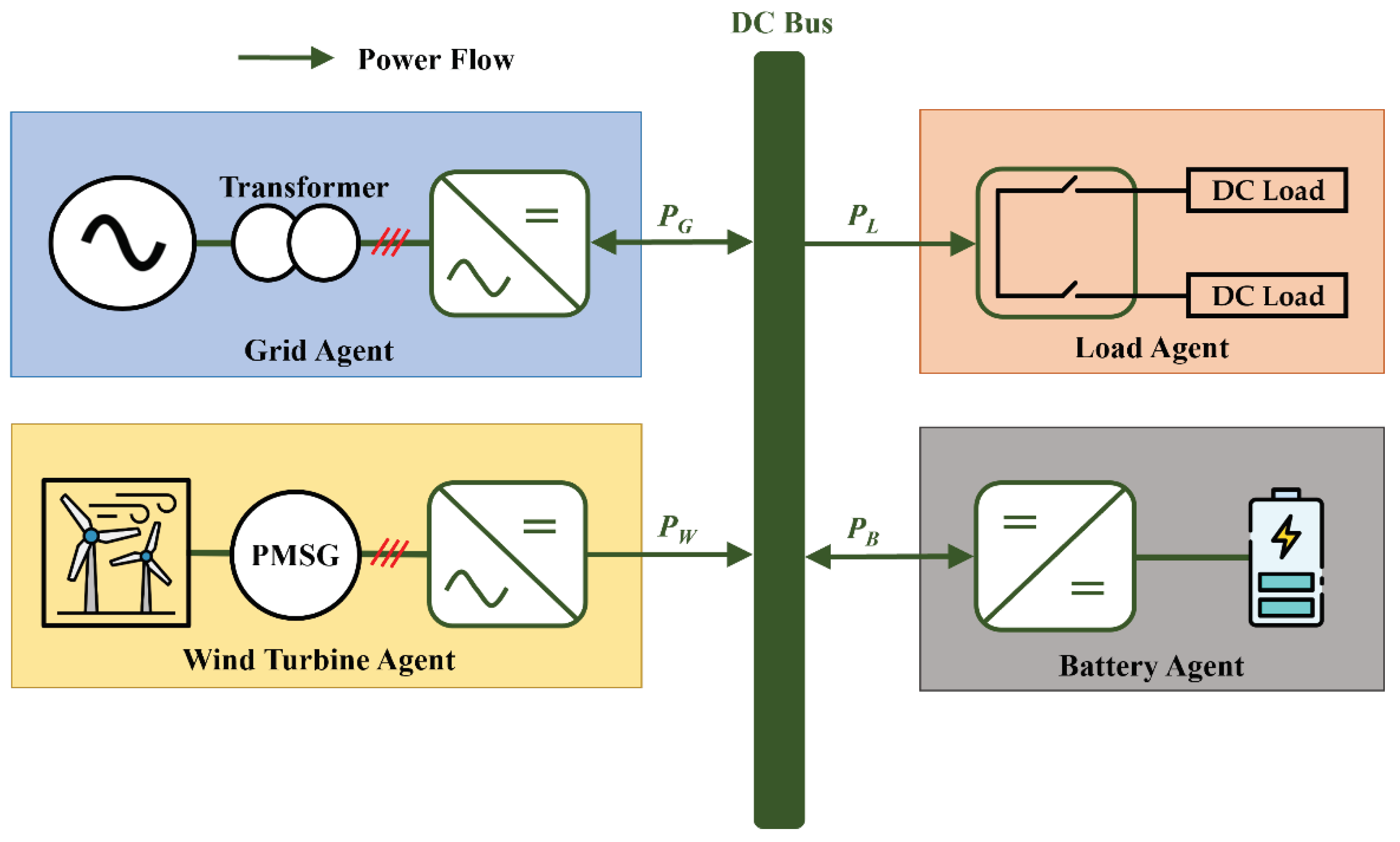
- The proposed decentralized control scheme achieves a continuous power management based on the transitional operation modes under system uncertainty and sensor failure, which greatly improves the system reliability. In addition, both voltage regulation and power sharing are accomplished by using only the primary controller to reduce the computational burden.
- (ii)
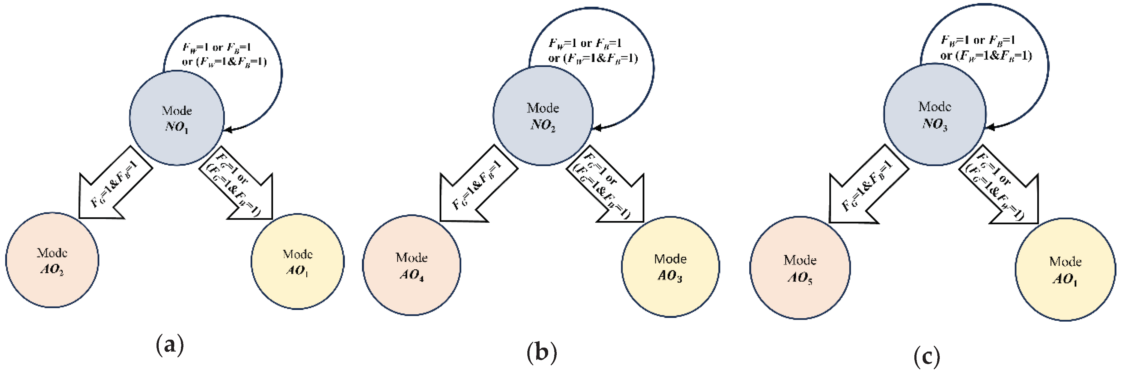
- Even under uncertain conditions such as the power variation of the distributed generation, the grid disconnection, the electricity price change, and critical battery status, the proposed decentralized DCMG system ensures voltage stabilization as well as the power balance by using the transitional operation modes without DCLs. Once an uncertain condition occurs, the DCV levels are temporarily adjusted to a proper level in transitional operation modes, and then, the power agents determine their operation modes based on the DCV levels.
- (iii)
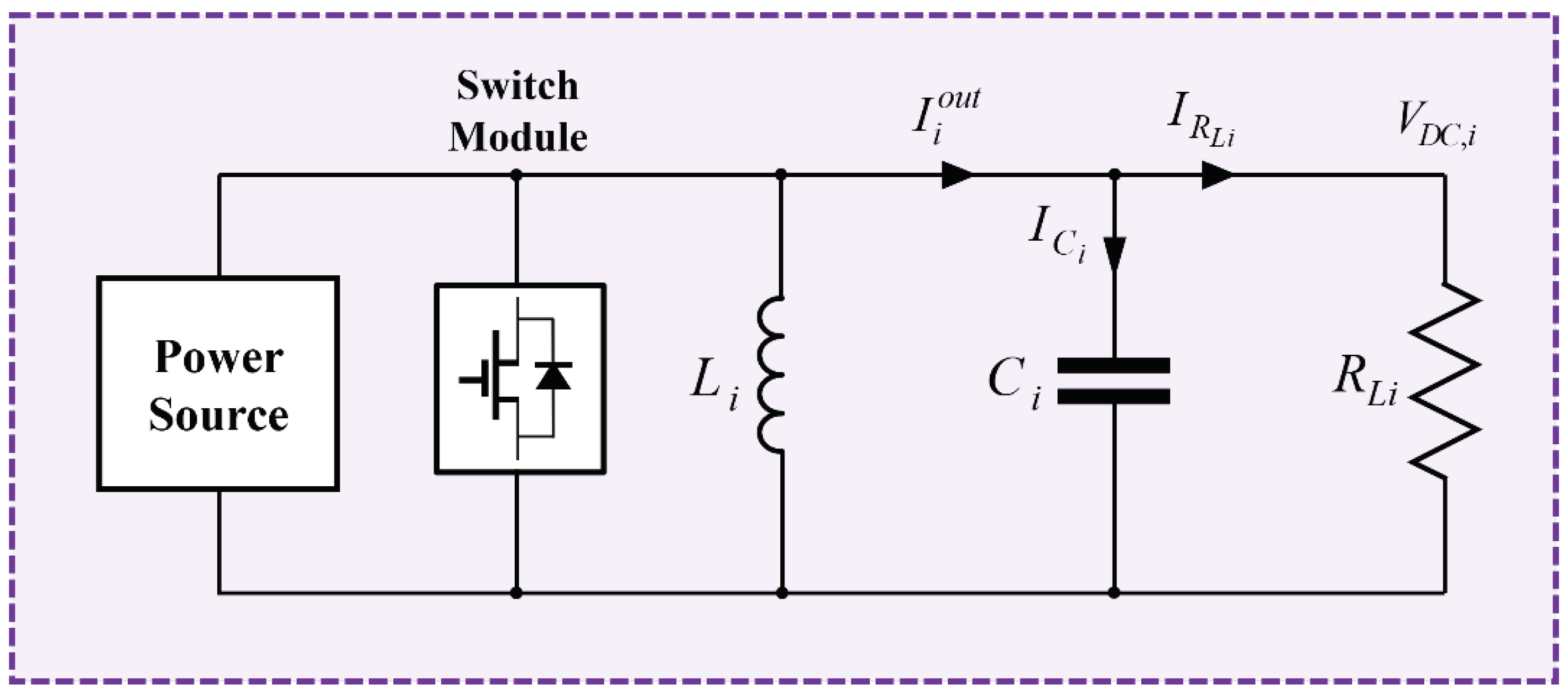
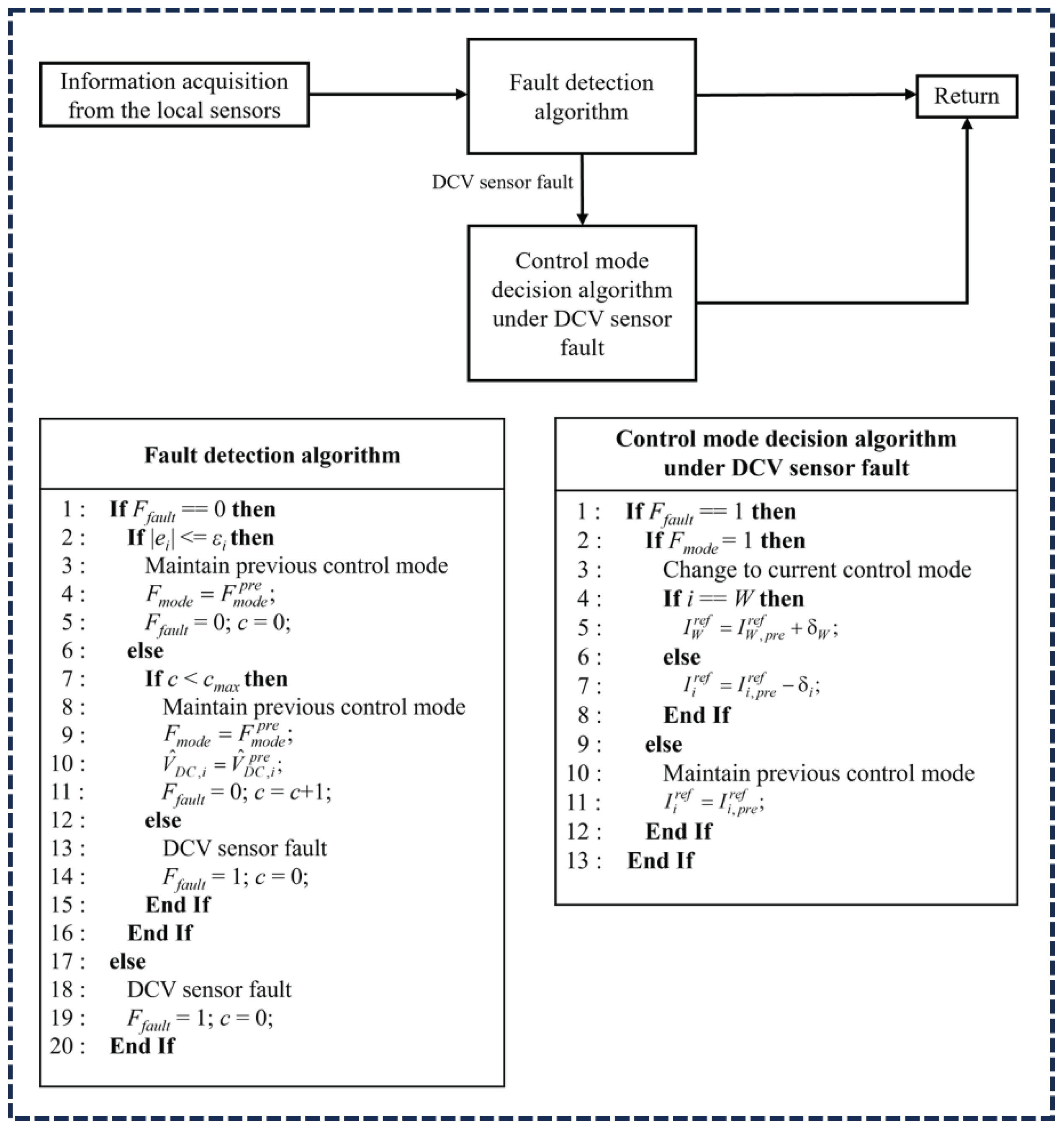
- To enhance the reliability of the DCMG system, the DCV sensor fault detection algorithm continuously monitors the abnormality of the DCV sensor in the proposed scheme. Under normal conditions without the DCV sensor failure, the proposed scheme achieves both voltage regulation and power balance. When the DCV sensor failure occurs in a power agent, the proposed control mode decision algorithm properly changes the operation of the power agent into the current control mode for seamless power management. In addition, the proposed scheme can stably work even under multiple DCV sensor faults in more than one power agent at the same time if there exists a normal DCV sensor in a DCMG system.
2. System Configuration of a DCMG and Decentralized Control Scheme
3. Control Strategy and Transition Operations of Power Agents under Emergency Conditions
3.1. Control Strategy of Power Agents
3.2. Control Strategy under DCV Sensor Fault
3.3. Transitional Operation Modes of Power Agents
4. Simulation Results
4.1. Transition between Grid-Connected Mode and Islanded Mode under DCV Sensor Fault
4.2. Transition from Normal to High Electricity Price Condition under DCV Sensor Fault
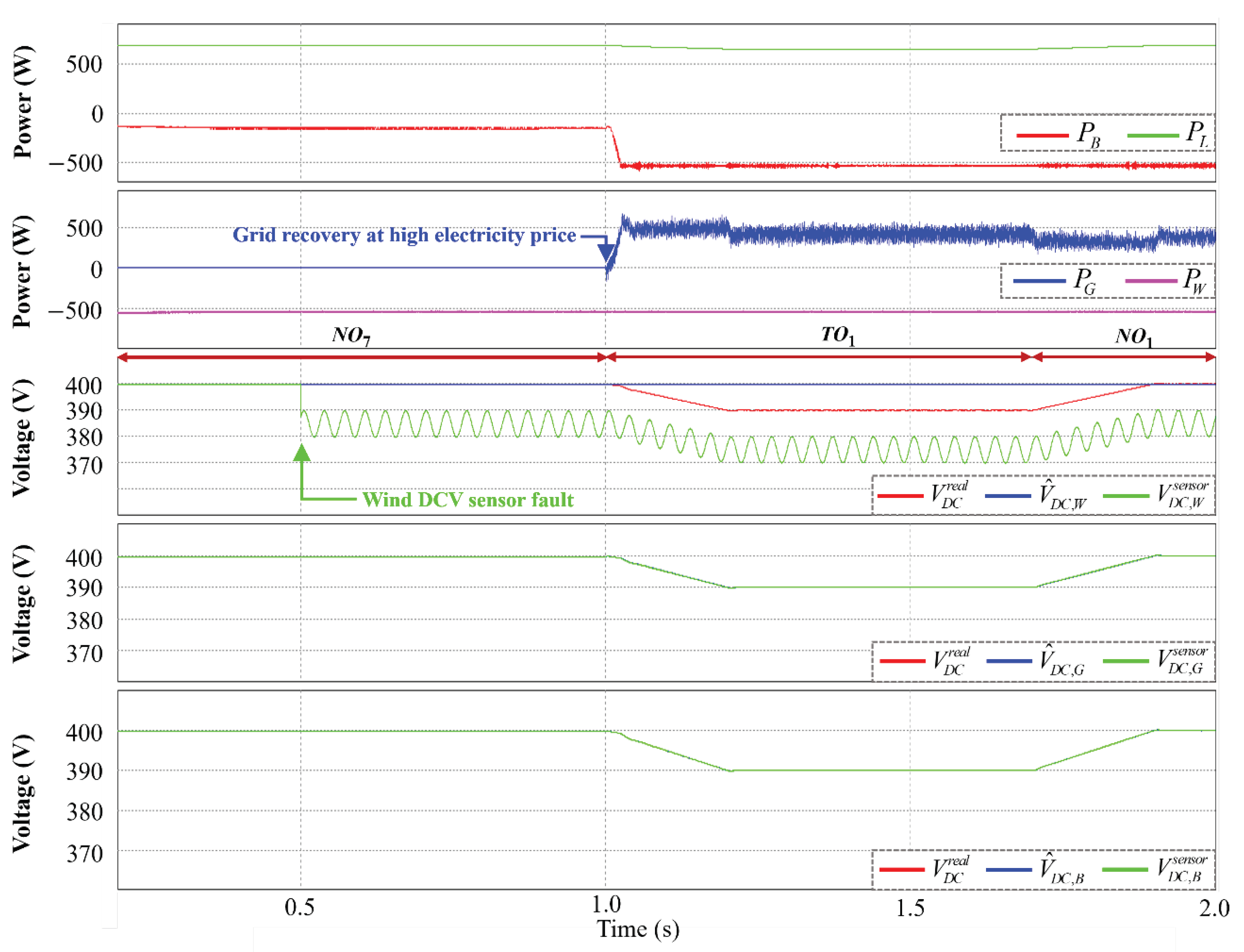
4.3. Grid Recovery with High Electricity Price Condition under DCV Sensor Fault
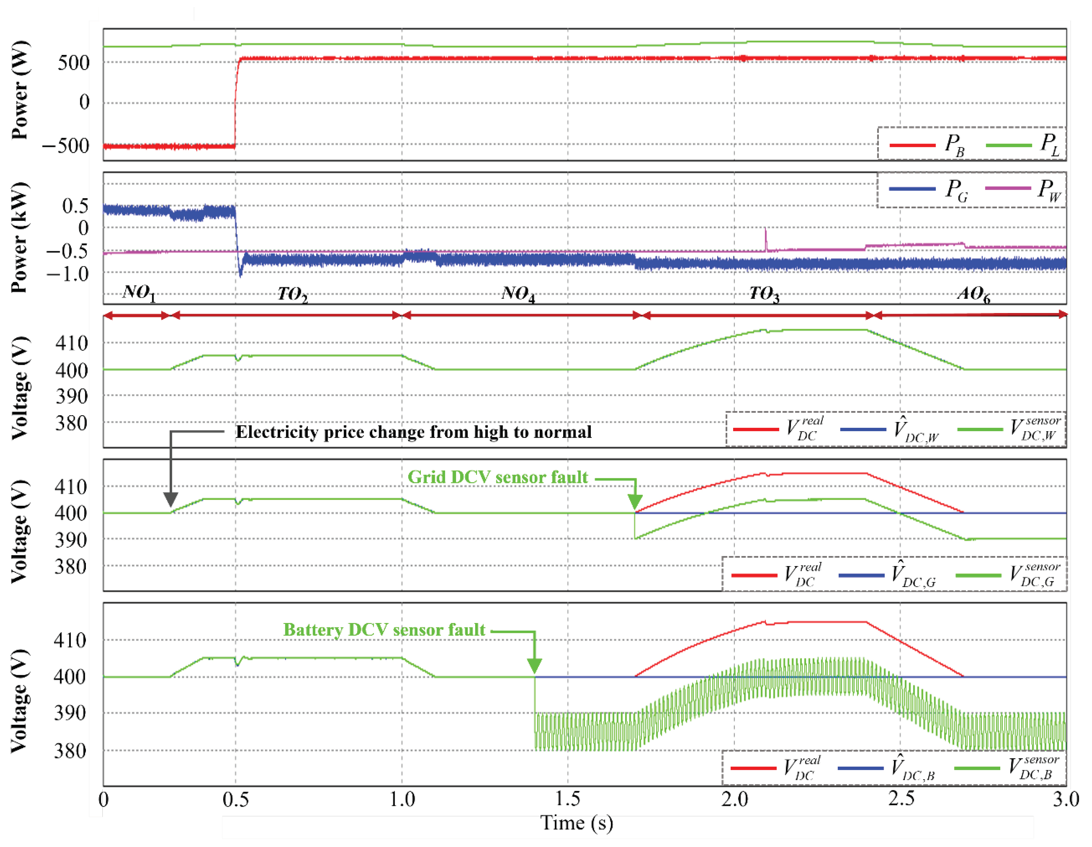
4.4. Transition from High to Normal Electricity Price Condition under DCV Sensor Fault
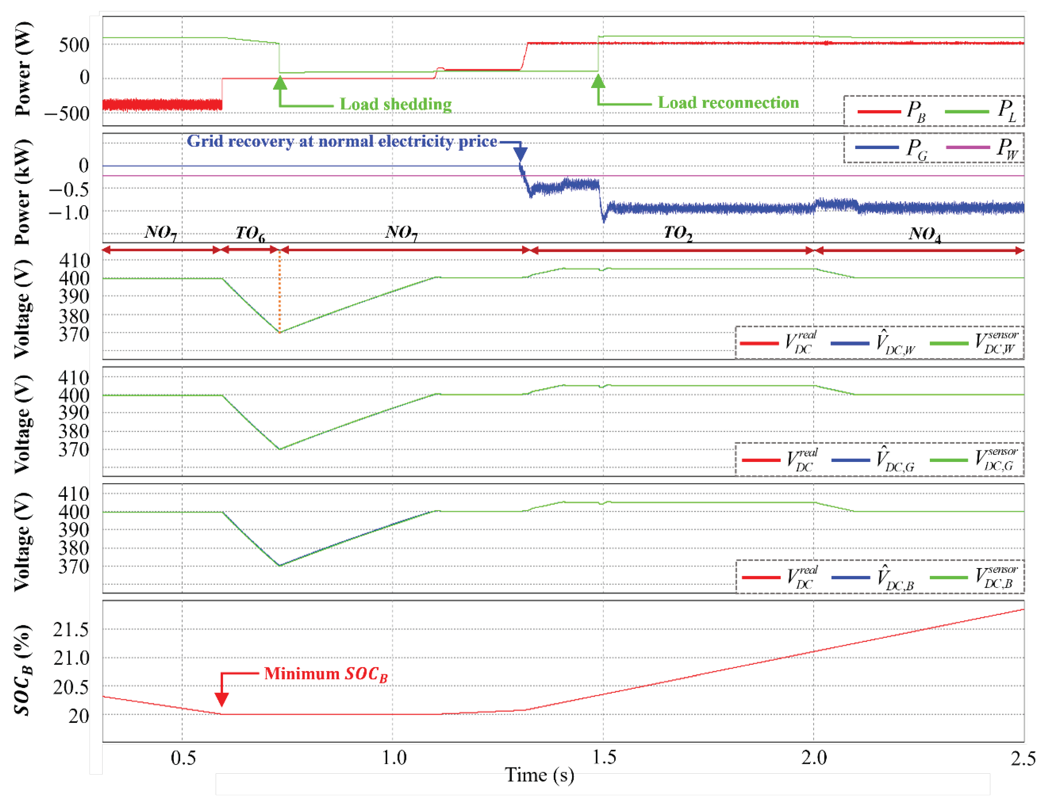
4.5. Case of Minimum Battery SOC Level
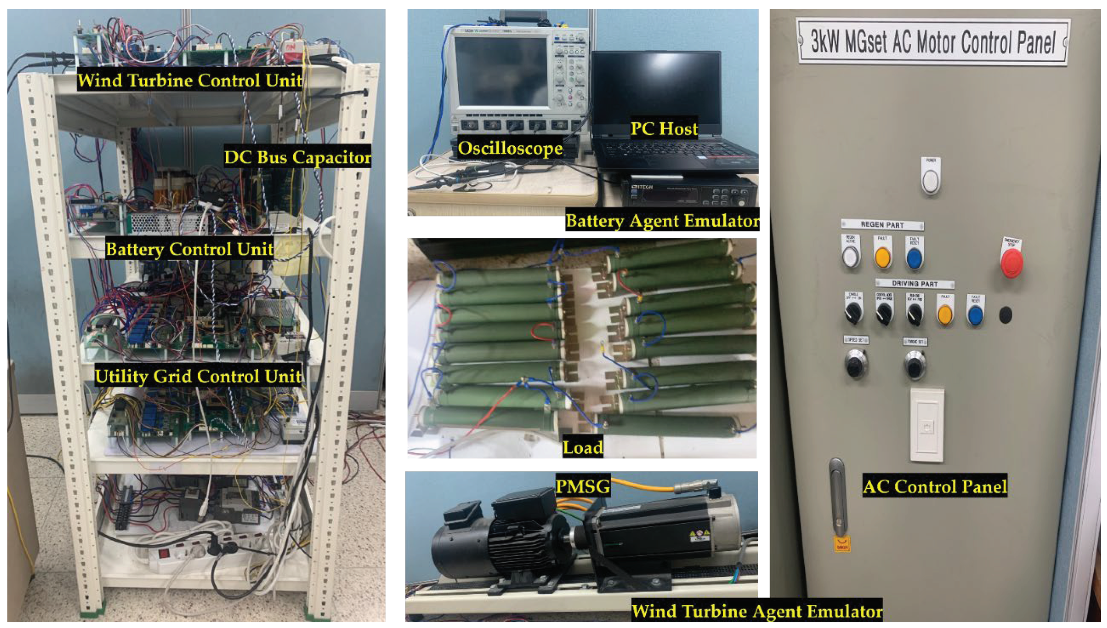
5. Experimental Results
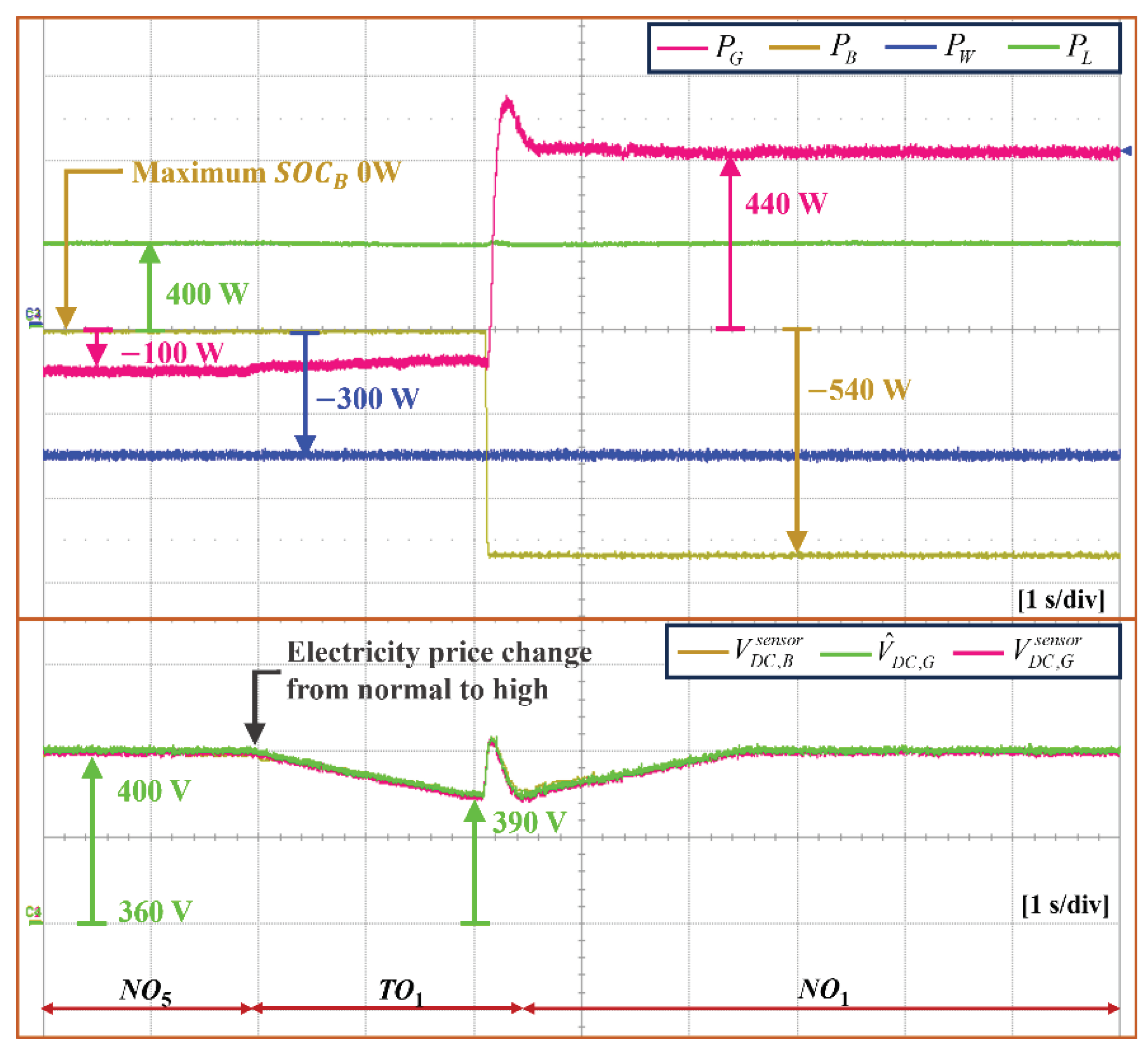
5.1. Transition from Normal to High Electricity Price Condition in Grid-Connected Mode
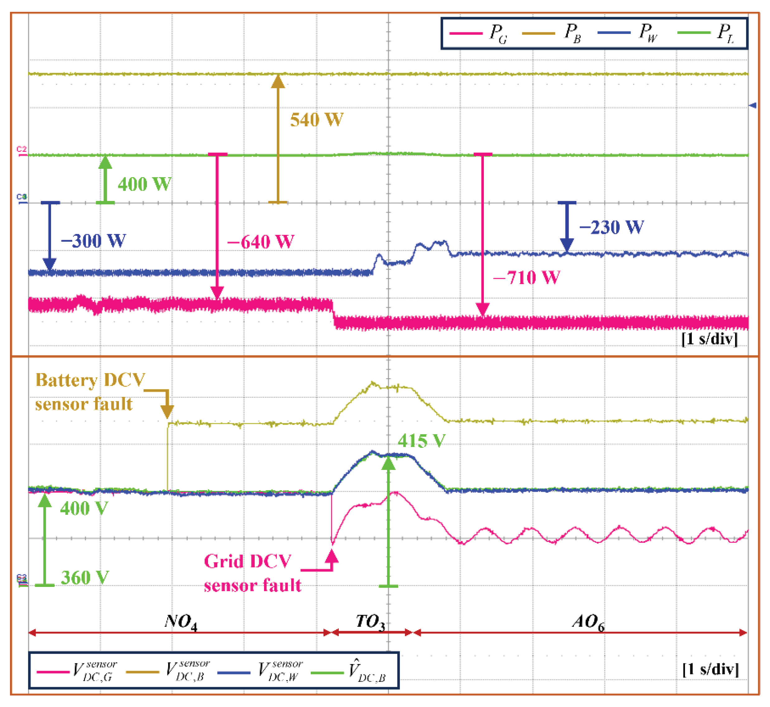
5.2. Grid-connected Mode under DCV Sensor Fault
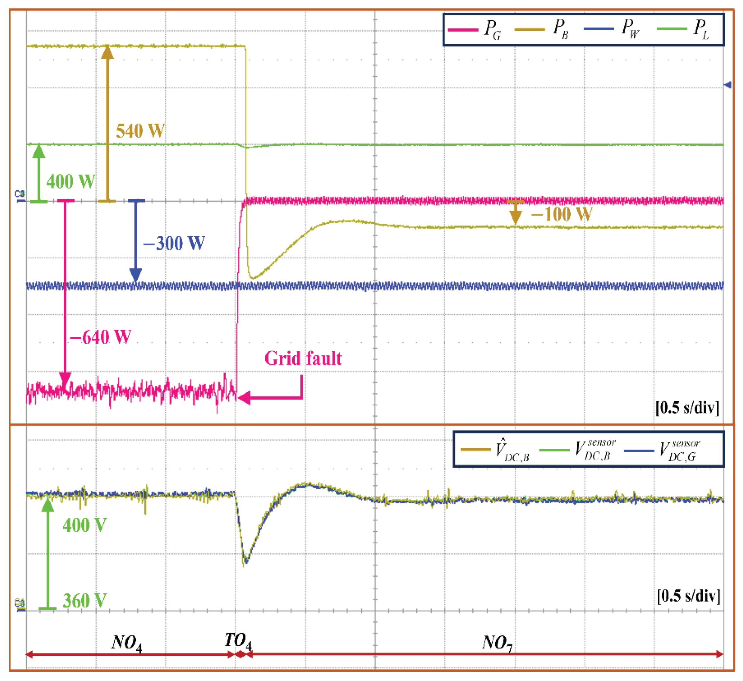
5.3. Transition between Grid-Connected Mode and Islanded Mode
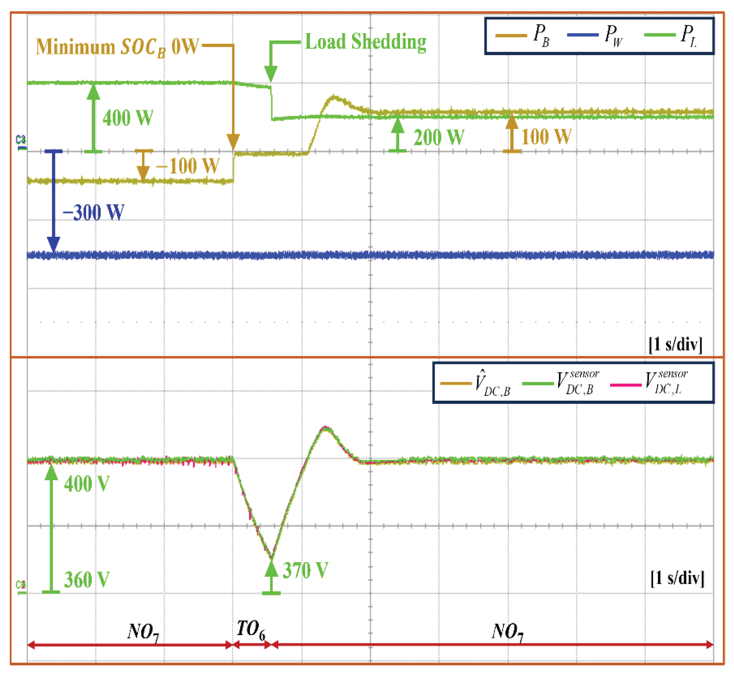
5.4. Islanded Mode under Minimum Battery SOC Level
5.5. Islanded Mode under DCV Sensor Fault
6. Conclusions
Author Contributions
Funding
Institutional Review Board Statement
Informed Consent Statement
Data Availability Statement
Conflicts of Interest
Abbreviations
| BCCMchar BCCMdis BVCM |
Battery Current Control Mode by charging operation Battery Current Control Mode by discharging operation Battery Voltage Control Mode |
| GCCMcon | Grid agent Current Control Mode by converter operation |
| GCCMinv | Grid agent Current Control Mode by inverter operation |
| GVCMcon | Grid agent Voltage Control Mode by converter operation |
| GVCMinv LCL |
Grid agent Voltage Control Mode by inverter operation Inductive-Capacitive-Inductive |
| MPPT | Maximum Power Point Tracking |
| PMSG VCM |
Permanent Magnet Synchronous Generator Wind turbine agent Voltage Control Mode |
References
- Ogunrinde, O.; Shittu, E.; Dhanda, K.K. Investing in renewable energy: Reconciling regional policy with renewable energy growth. IEEE Eng. Manag. Rev. 2018, 46, 103–111. [Google Scholar] [CrossRef]
- Qazi, A.; Hussain, F.; Rahim, N.A.; Hardaker, G.; Alghazzawi, D.; Shaban, K.; Haruna, K. Towards sustainable energy: A systematic review of renewable energy sources, technologies, and public opinions. IEEE Access 2019, 7, 63837–63851. [Google Scholar] [CrossRef]
- Dugan, R.C. Challenges in considering distributed generation in the analysis and design of distribution system. 2008 IEEE Power and Energy Society General Meeting – Conversion and Delivery of Electrical Energy in the 21st Century, Pittsburg, USA, 2008. [Google Scholar] [CrossRef]
- Huang, S.-J.; Hsieh, C.-W.; Wan, H.-H. Confirming the permissible capacity of distributed generation for grid-connected distribution feeders. IEEE Trans. Power Syst. 2015, 30, 540–541. [Google Scholar] [CrossRef]
- Su, S.-Y.; Lu, C.-N.; Chang, R.-F.; Guillermo, G.-A. Distributed generation interconnection planning: A wind power case study. IEEE Trans. Smart Grid 2011, 2, 181–188. [Google Scholar] [CrossRef]
- Mohanty, S.; Bhanja, A.; Gautam, S.P.; Chittathuru, D.; Dash, S.K.; Mangaraj, M.; Chinthaginjala, R.; Alamri, A.M. Review of a comprehensive analysis of planning, functionality, control, and protection for direct current microgrids. Sustainability 2023, 15, 15405. [Google Scholar] [CrossRef]
- Cabana-Jiménez, K.; Candelo-Becerra, J.E.; Sousa Santos, V. Comprehensive analysis of microgrids configurations and topologies. Sustainability 2022, 14, 1056. [Google Scholar] [CrossRef]
- Kumar, D.; Zare, F.; Ghosh, A. DC microgrid technology: System architectures, AC grid interfaces, grounding schemes, power quality, communication networks, applications, and standardizations aspects. IEEE Access 2017, 5, 12230–12256. [Google Scholar] [CrossRef]
- Santoro, D.; Delmonte, N.; Simonazzi, M.; Toscani, A.; Rocchi, N.; Sozzi, G.; Cova, P.; Menozzi, R. Local power distribution—A review of nanogrid architectures, control strategies, and converters. Sustainability 2023, 15, 2759. [Google Scholar] [CrossRef]
- Keshavarzi, D.; Farjah, E.; Ghanbari, T. Hybrid DC circuit breaker and fault current limiter with optional interruption capability. IEEE Trans. Power Electron. 2018, 33, 2330–2338. [Google Scholar] [CrossRef]
- Lotfi, H.; Khodaei, A. AC versus DC microgrid planning. IEEE Trans. Smart Grid 2017, 8, 296–304. [Google Scholar] [CrossRef]
- Zhou, L.; Zhang, Y.; Lin, X.; Li, C.; Cai, Z.; Yang, P. Optimal sizing of PV and BESS for a smart household considering different price mechanisms. IEEE Access 2018, 6, 41050–41059. [Google Scholar] [CrossRef]
- Al-Ismail, F.S. DC microgrid planning, operation, and control: A comprehensive review. IEEE Access 2021, 9, 36154–36172. [Google Scholar] [CrossRef]
- Saleh, M.; Esa, Y.; Hariri, M.E.; Mohamed, A. Impact of information and communication technology limitations on microgrid operation. Energies 2019, 12, 2926. [Google Scholar] [CrossRef]
- Abbasi, M.; Abbasi, E.; Li, L.; Aguilera, R.P.; Lu, D.; Wang, F. Review on the microgrid concept, structures, components, communication systems, and control methods. Energies 2023, 16, 484. [Google Scholar] [CrossRef]
- Van Nguyen, T.; Kim, K.-H. Power flow control strategy and reliable DC-link voltage restoration for DC microgrid under grid fault conditions. Sustainability 2019, 11, 3781. [Google Scholar] [CrossRef]
- Mehdi, M.; Kim, C.-H.; Saad, M. Robust centralized control for DC islanded microgrid considering communication network delay. IEEE Access 2020, 8, 77765–77778. [Google Scholar] [CrossRef]
- Yu, Y.; Liu, G.-P.; Huang, Y.; Guerrero, J.M. Distributed data-driven secondary regulation for the conflict between voltage recovery and accurate current sharing in DC microgrids. IEEE Trans. Power Electron. 2023, 38, 9617–9634. [Google Scholar] [CrossRef]
- Espina, E.; Llanos, J.; Burgos-Mellado, C.; Cárdenas-Dobson, R.; Martínez-Gómez, M.; Sáez, D. Distributed control strategies for microgrids: An overview. IEEE Access 2020, 8, 193412–193448. [Google Scholar] [CrossRef]
- Li, Q.; Chen, F.; Chen, M.; Guerrero, J.M.; Abbott, D. Agent-based decentralized control method for islanded microgrids. IEEE Trans. Smart Grid 2016, 7, 637–649. [Google Scholar] [CrossRef]
- Bani-Ahmed, A.; Rashidi, M.; Nasiri, A.; Hosseini, H. Reliability analysis of a decentralized microgrid control architecture. IEEE Trans. Smart Grid 2019, 10, 3910–3918. [Google Scholar] [CrossRef]
- Gu, Y.; Xiang, X.; Li, W.; He, X. Mode-adaptive decentralized control for renewable DC microgrid with enhanced reliability and flexibility. IEEE Trans. Power Electron. 2014, 29, 5072–5080. [Google Scholar] [CrossRef]
- Wang, C.; Duan, J.; Fan, B.; Yang, Q.; Liu, W. Decentralized high-performance control of DC microgrids. IEEE Trans. Smart Grid 2019, 10, 3355–3363. [Google Scholar] [CrossRef]
- Xia, Y.; Yu, M.; Tao, X.; Peng, Y.; Wei, W. Decentralized control for parallel bidirectional power converters of a grid-connected DC microgrid. IECON 2016 - 42nd Annual Conference of the IEEE Industrial Electronics Society, Florence, Italy, 2016. [Google Scholar] [CrossRef]
- Xu, L.; Chen, D. Control and operation of a DC microgrid with variable generation and energy storage. IEEE Trans. Power Delivery 2011, 26, 2513–2522. [Google Scholar] [CrossRef]
- Chen, D.; Xu, L.; Yao, L. DC voltage variation based autonomous control of DC microgrids. IEEE Trans. Power Delivery 2013, 28, 637–648. [Google Scholar] [CrossRef]
- Tahim, A.P.N.; Pagano, D.J.; Lenz, E.; Stramosk, V. Modeling and stability analysis of islanded DC microgrids under droop control. IEEE Trans. Power Electron. 2015, 30, 4597–4607. [Google Scholar] [CrossRef]
- Li, X.; Guo, L.; Zhang, S.; Wang, C.; Li, Y.W.; Chen, A.; Feng, Y. Observer-based DC voltage droop and current feed-forward control of a DC microgrid. IEEE Trans. Smart Grid 2018, 9, 5207–5216. [Google Scholar] [CrossRef]
- Gao, F.; Bozhko, S.; Costabeber, A.; Patel, C.; Wheeler, P.; Hill, C. I.; Asher, G. Comparative stability analysis of droop control approaches in voltage-source-converter-based DC microgrids. IEEE Trans. Power Electron. 2017, 32, 2395–2415. [Google Scholar] [CrossRef]
- Jabbar, M.A.M.; Tran, D.T.; Kim, K.-H. Decentralized power flow control strategy using transition operations of DC-bus voltage for detection of uncertain DC microgrid operations. Sustainability 2023, 15, 11635. [Google Scholar] [CrossRef]
- Habibullah, A.F.; Kim, K.-H. Decentralized power management of DC microgrid based on adaptive droop control with constant voltage regulation. IEEE Access 2022, 10, 129490–129504. [Google Scholar] [CrossRef]
- Tran, D.T.; Kim, M.; Kim, K.-H. Seamless power management for decentralized DC microgrid under voltage sensor faults. IEEE Access 2023, 11, 74627–74640. [Google Scholar] [CrossRef]
- Dehkordi, N.M.; Moussavi, S.Z. Distributed resilient adaptive control of islanded microgrids under sensor/actuator faults. IEEE Trans. Smart Grid 2020, 11, 2699–2708. [Google Scholar] [CrossRef]
- Oritz-matos, L.; Zea, L.B.G.; Gonzalez-sanchez, J.W. A methodology of sensor fault-tolerant control on a hierarchical control for hybrid microgrids. IEEE Access 2023, 11, 58078–58098. [Google Scholar] [CrossRef]
- Chandra, M.V.S.S.; Mohapatro, S. Hybrid sensor fault tolerant control of low voltage DC microgrid. IEEE Trans. Ind. Appl 2024, 60, 1705–1715. [Google Scholar] [CrossRef]
- Kong, X.; Cai, B.; Liu, Y.; Zhu, H.; Yang, C.; Gao, C.; Liu, Y.; Liu, Z.; Ji, R. Fault diagnosis methodology of redundant closed-loop feedback control systems: Subsea blowout preventer system as a case study. IEEE Trans. Syst. Man Cybern. Syst. 2023, 53, 1618–1629. [Google Scholar] [CrossRef]
- Jessen, K.; Soltani, M.; Hajizadeh, A. Sensor fault detection for line regulating converters supplying constant power loads in DC microgrids. 2020 IEEE 11th International Symposium on Power Electronics for Distributed Generation Systems, Dubrovnik, Croatia, 2020. [Google Scholar] [CrossRef]
- Huang, M.; Ding, L.; Li, W.; Chen, C.Y.; Liu, Z. Distributed observer-based H∞ fault-tolerant control for DC microgrids with sensor fault. IEEE Trans. Circuits Syst. I Regul. Pap. 2021, 68, 1659–1670. [Google Scholar] [CrossRef]

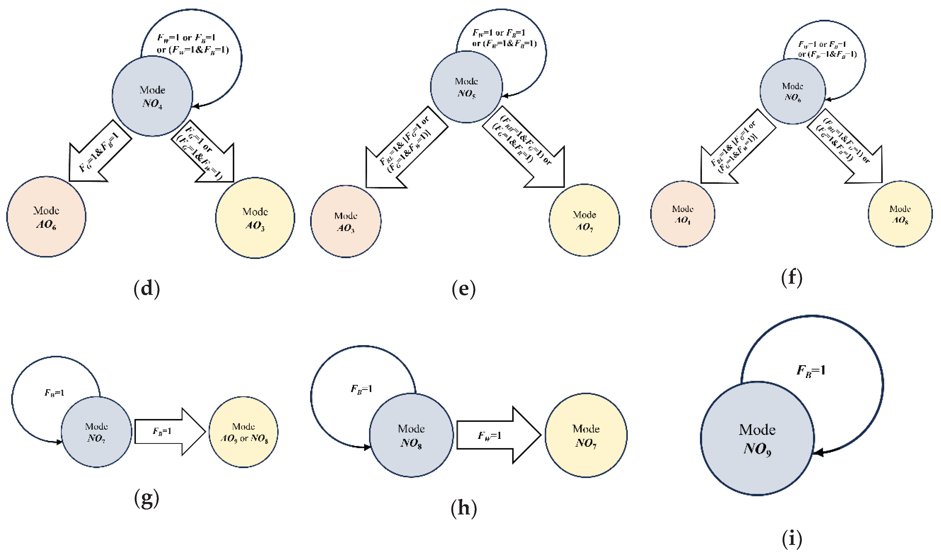
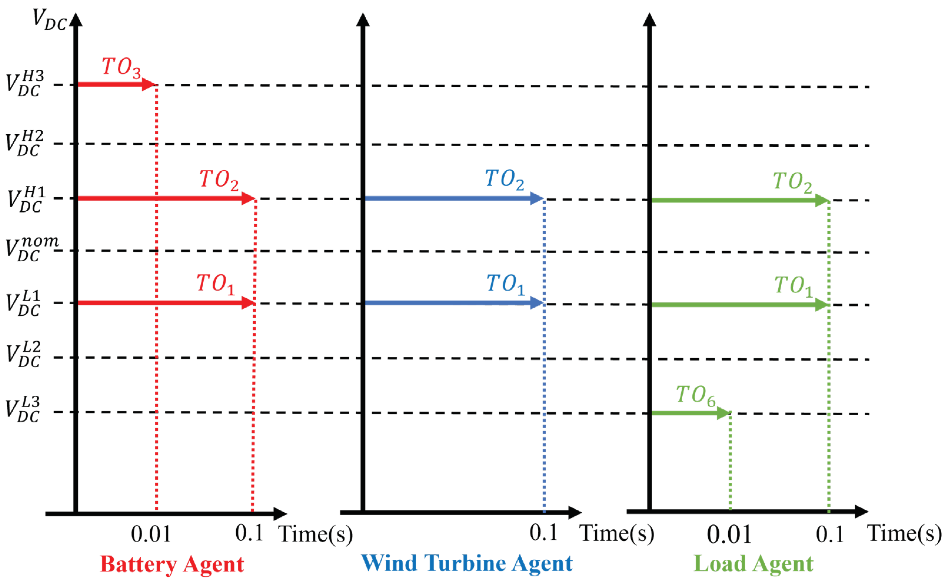
| Mode | Battery Agent | Wind Turbine Agent | Grid Agent | Load Agent |
|---|---|---|---|---|
| NO1 | BCCMdis | MPPT | GVCMinv | NOR |
| NO2 | BCCMdis | MPPT | GVCMcon | NOR |
| NO3 | BCCMchar | MPPT | GVCMinv | NOR |
| NO4 | BCCMchar | MPPT | GVCMcon | NOR |
| NO5 | IDLE | MPPT | GVCMcon | NOR |
| NO6 | IDLE | MPPT | GVCMinv | NOR |
| NO7 | BVCM | MPPT | Fault | NOR |
| NO8 | BCCMchar | VCM | Fault | NOR |
| NO9 | IDLE | VCM | Fault | NOR |
| Mode | Battery Agent | Wind Turbine Agent | Grid Agent | Load Agent |
|---|---|---|---|---|
| AO1 | BVCM | MPPT | GCCMinv | NOR |
| AO2 | BCCMdis | VCM | GCCMinv | NOR |
| AO3 | BVCM | MPPT | GCCMcon | NOR |
| AO4 | BCCMdis | VCM | GCCMcon | NOR |
| AO5 | BCCMchar | VCM | GCCMinv | NOR |
| AO6 | BCCMchar | VCM | GCCMcon | NOR |
| AO7 | IDLE | VCM | GCCMcon | NOR |
| AO8 | IDLE | VCM | GCCMinv | NOR |
| AO9 | BCCMdis | VCM | Fault | NOR |
| Mode | Grid Agent | Wind Turbine Agent | Battery Agent | Agent Action |
|---|---|---|---|---|
| TO1 | ✔ |
|
||
| TO2 | ✔ |
|
||
| TO3 | ✔ | ✔ |
|
|
| TO4 | ✔ | ✔ |
|
|
| TO5 | ✔ |
|
||
| TO6 | ✔ | ✔ | ✔ |
|
| Power Agents | Parameters | Value |
|---|---|---|
| Battery agent | Minimum SOC () Maximum SOC () Maximum discharging power Maximum charging power Maximum voltage Rated capacity Converter filter inductance L |
20 % 90 % 540 W 540 W 180 V 25 Ah 7 mH |
| Grid agent | Transformer Υ/Δ Grid frequency Grid voltage Filter capacitance of LCL filter Inverter-side inductance of LCL filter Grid-side inductance of LCL filter |
380/220 V 60 Hz 220 V 4.5 μF 1.7 mH 1.7 mH |
| Wind turbine agent | PMSG number of poles PMSG inertia PMSG stator resistance PMSG dq-axis inductance PMSG flux linkage Converter filter inductance |
6 0.111 kgm2 0.64 Ω 0.82 mH 0.18 Wb 7 mH |
| Load agent | Power of load 1 Power of load 2 Power of load 3 Priority level : load 1 > load 2 > load 3 |
200 W 200 W 200 W - |
| DC bus | Nominal DCV (Vnom) First level of high DCV (VH1) Second level of high DCV (VH2) Third level of high DCV (VH3) First level of low DCV (VL1) Second level of low DCV (VL2) Third level of low DCV (VL3) Capacitance |
400 V 405 V 410 V 415 V 390 V 380 V 370 V 4 mF |
Disclaimer/Publisher’s Note: The statements, opinions and data contained in all publications are solely those of the individual author(s) and contributor(s) and not of MDPI and/or the editor(s). MDPI and/or the editor(s) disclaim responsibility for any injury to people or property resulting from any ideas, methods, instructions or products referred to in the content. |
© 2024 by the authors. Licensee MDPI, Basel, Switzerland. This article is an open access article distributed under the terms and conditions of the Creative Commons Attribution (CC BY) license (http://creativecommons.org/licenses/by/4.0/).


