1. Introduction
The development of UVs (e.g., air, land, surface, submersible, amphibious) present an exponential growth that accompanies the inherent technological evolution as well as the identification of the different needs that are being established by the different areas of the civil and military sectors.
The origins of UVs date back to the end of the 19th century, when Nikola Tesla [
1] developed two steel vessels of approximately 1.80m, equipped with radio receivers which, connected to electromechanical actuators, controlled the steering of the vessel and an electric propulsion system.
The experience acquired during the wars in the beginning of the 20th century, e.g., Russo-Japanese War (1904-1905), First World War (1914-1918), led to the initial development of remotely controlled ground vehicles [
2] and vessels that transported an explosive charge with the objective that it would detonate after impact with enemy fortifications. Improvements proceeded and in the initial phase of the Second World War (1939-1945), the Soviet Red Army used remotely controlled unmanned tanks equipped with machine guns, flamethrowers, smoke canisters and a 200–700kg time bomb, with a 1500m maximum operating range, to reduce combat risk to soldiers [
3].
The initial research on autonomous UGVs may be dated back to the late 1960’s in which the application of artificial intelligence for controlling vehicles, in a project funded by the Defense Advanced Research Projects Agency (DARPA) and developed at Stanford Research Institute. This research led to a mobile wheeled robot SHAKEY [
4,
5] with a steerable TV camera, ultrasonic range finder and touch range sensors connected via radio (RF link) to a central computer (SDS-940) capable of performing autonomous navigation and exploration tasks. Even though SHAKEY never achieved autonomous operation, it paved the ground to define the AI research agenda [
6].
In the 1970′s, Hans Moravec, leader of the Stanford Cart project, explored the navigation and obstacle avoidance issues using a sophisticated stereo vision system leading to the development of an indoor platform rover [
7]. In the early 1980′s, the Naval Ocean Systems Center undertook reconnaissance, surveillance, and target acquisition oriented UGVs projects that could provide a battlefield commander with a direct sensing capability on the battleground and behind enemy lines, without endangering human personnel [
8]. To develop and refine UGVs operational concepts, in the 1990′s, the Surrogate Teleoperated Vehicle program, initiated by Robotics Systems Technology, lead to a six-wheel all-terrain vehicle operated using stereo TV imagery, via either RF or fiber optic cable datalink, and equipped with a GPS receiver improve navigation [
9].
In 2003, DARPA announced the Grand Challenge [
10], a project to accelerate UGV technology in military missions. From 2010, the development of UGVs entered a new phase as many automobile manufacturers (e.g., Mercedes-Benz) and IT companies (e.g., Google) started to switch their attention to this field [
11]. In the last decade, the exponential growth of artificial intelligence, machine learning and other deep learning algorithms [
12] have contributed for the development of many advanced UGVs with improved capabilities, e.g., sensing and control. Some relevant state of the art reviews in the civil and military sectors are available in the current literature [
13,
14,
15,
16,
17].
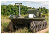
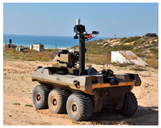
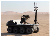
The variety of UGVs led to a classification [
17], based on three categories: size, mode of operation and type of weapon. Each category contemplates four classes. This classification is useful in the design of new (or selection of existing) UGVs to execute one or more types of missions such as surveillance and reconnaissance, search and rescue, deactivation of explosive devices, transport of troops and equipment, use of weapons, among others. To fulfill multi-operational scenarios, in the last decade, several UGVs have been developed with enhanced amphibious capabilities, see
Table 1. However, none of these UGVs, among others that were surveyed, fully comply with the expected specifications of the envisioned A-UGV here established.
The development of this conceptual A-UGV is motivated by the DEM 2018 REV 2021 [
18], in which this work encompasses several lines of action of the strategic objectives from the operational perspective, namely: a) optimize the presence and control in maritime spaces under national sovereignty or jurisdiction; b) increase the readiness of operational units and their commitment to support foreign policy and c) consolidate knowledge and action within the framework of marine sciences and maritime culture. Additionally, this work is a foundation that aims to further strengthen the presence of Portugal and the Portuguese Navy in NATO exercises, e.g., the Recognized Environmental Picture Augmented by Maritime Unmanned Systems (REP(MUS)).
Another significant motivation for the development of an A-UGV concerns the line of action 8.02 of the DEM 2018 REV 2021 [
18], which promotes the reinforcement of the intervention capacity in civilian emergencies, humanitarian emergencies, and post-catastrophe intervention missions. Since forest fires are one of the main hazards in Portugal [
19], and often occur in locations of difficult access constrained by rivers and lakes, A-UGVs are an excellent tool for building fire lines for backfire operations and surveying fire perimeters to detect hot spots [
20].
Therefore, this work focuses on the conceptual design of an A-UGV with the following characteristics: fully electric, modular (in the sense that it can incorporate different sensors suitable for the mission to be carried out), portable (two man carriable) and with low production, maintenance and operational costs.
2. Materials and Methods
The general conceptual product development process [
21] is here adapted and includes the following phases:
2.1). Identification of the needs;
2.2). Target specifications;
2.3). Market research analysis;
2.4). Conceptualization and development;
2.5). Establishment of the final specifications.
Note there is a correlation between this methodology and others adopted in the development of naval military projects [
22,
23], in which all use a sequential and iterative approach to obtain the most efficient and effective final product. Following, a summary of each phase of the conceptual product development process is presented.
In line with our project’s focus on meeting the requirements of the Portuguese Navy, our primary objective during this phase is to establish specifications tailored specifically to their needs. The detailed design of the A-UGV, including its propulsion system, will be addressed in subsequent stages. As such, the current analysis of the water propulsion system is conducted without specifying its configuration or efficiency.
2.1. Identification of the Needs
The motivations established promote the identification of the needs for the conceptual development of the A-UGV.
2.2. Target Specifications
The target specifications, or (operational) requirements, are thus directly related to the needs identified, providing a precise description of its main characteristics. These translate the identified needs into specific technical parameters that are at this stage refined to be consistent with the defined objectives and with the constraints associated with the concept.
2.3. Market Research
A state-of-the-art research survey is conducted to establish a better understanding of the current available solutions, determine their main common characteristics, and analyze the technological advances.
2.4. Conceptualization and Development
The creation of new concepts involves research, innovation and analysis of associated constraints. By combining the target specifications with the desired characteristics, 3D Computer Aided Design (CAD) is used to generate conceptual designs of the different components, e.g., the hull, of the A-UGV. At this stage the material of each component is defined, allowing the CAD model of the vehicle for parameter extraction, e.g., center of gravity, to be further used in numerical simulations, namely, the structural static and dynamic integrity of the A-UGV.
The choice and conceptualization considered most adequate is based on the evaluation of the two most common configurations, i.e., tracks and/or wheels. To aid in decision-making, empirical considerations are used to assess the main advantages and disadvantages inherent to each configuration. From the information acquired, and considering the application and the means in which the A-UGV will operate, a decision is made.
2.4.1. Land Propulsion
For the set configuration, it is now necessary to establish the motors and batteries. The methodology adopted includes an iterative process to estimate the total engine power required that may be expressed as,
in which,
is the total mass of the vehicle (includes the mass of the hull, wheels, motors and batteries, being the last two iteratively estimated),
is the mass of the payload,
is the maximum slope angle,
is the gravitational acceleration,
is the dynamic friction coefficient between the ground and the wheels and
is the maximum rated speed.
The energy capacity of the batteries
may be estimated as,
where is the
autonomy,
is the voltage of the motor and
and
are the performance of the engine and of the battery discharge, respectively.
Furthermore, the following mission profile, of interest to the Portuguese Navy, is defined: i) a first 4000m plane segment followed by a 15° positive slope; ii) a second 4000m plane segment followed by a 15° positive slope; iii) a third 4000m plane segment followed by a 15° negative slope; iv) a fourth 4000m plane segment followed by a 15° negative slope; and v) a fifth 4000m plane segment. It is considered a dynamic friction coefficient (μ=0.7, approximately that of rubber on cement [
24] and that the speeds for the plane and sloped segments are travelled at speeds of 20km/h (maximum projected speed) and 15km/h, respectively.
2.4.2. Hydrostatic and Intact Stability Analyses
Having established a conceptual model of the vehicle, hydrostatic and intact stability analyses are conducted using inhouse naval architecture software. The CAD model of the vehicle (including associated mass properties) is imported in which the height of the water level is defined leading to a hydrostatic report that includes, among others, the center of buoyancy, the center of gravity, the vertical center of gravity, the metacentric height and trimming moment [
25].
2.4.3. Water Propulsion
To estimate the power required to make the vehicle reach the maximum specified water speed, it is necessary to estimate its drag force. For this, Altair® HyperWorksTM with the AcuSolveTM solver is used to which the CAD model of the vehicle is imported. After performing a convergence study and based on the computational cost of the simulations, the choice rested on using a domain discretized in 1.1 million trimmed cells. A far field boundary condition, with enough length to minimize the flow disturbance caused by the vehicle, is set; and prism layers, with an all-y+ wall treatment, are used on the vehicle hull, shaft and wheels for improved discretization of the boundary layers. The time-averaged Navier-Stokes equations are closed by the realizable κ-ε turbulence model that shows better performance for flows involving rotation, boundary layers under strong adverse pressure gradients, separation and recirculation.
A close volume is used to conduct the simulation in which: the inlet is taken as a velocity inlet, with a velocity of 4.116m/s (8kts); the far field boundary is modelled as a pressure outlet with prescribed pressure (, where is the waterline level (0.2m) and is set to zero relative to the atmospheric pressure; and the other volume walls are taken as symmetry.
To ensure that the established autonomy is fulfilled, and the batteries estimated for the land profile mission, a second mission profile in which the vehicle travels mostly in water is specified. It consists of: i) a first 4000m plane segment; ii) a second 20000m water segment; and iii) a third 4000m plane segment. It is considered a dynamic friction coefficient of 0.6 (approximately that of sand or loose gravel) and that the speeds for the plane and water segments are travelled at speeds of 20km/h (maximum projected speed) and 8kts, respectively.
2.4.4. Static and Dynamic Structural Analysis
As a complement to the conceptual development of this A-UVG, static and dynamic structural analyzes are carried out, using Altair SimSolid® which is a meshless method based on the theory of external approximations (Apanovitch, 2021), to evaluate the design as well as some of the options considered during the conceptualization of the vehicle.
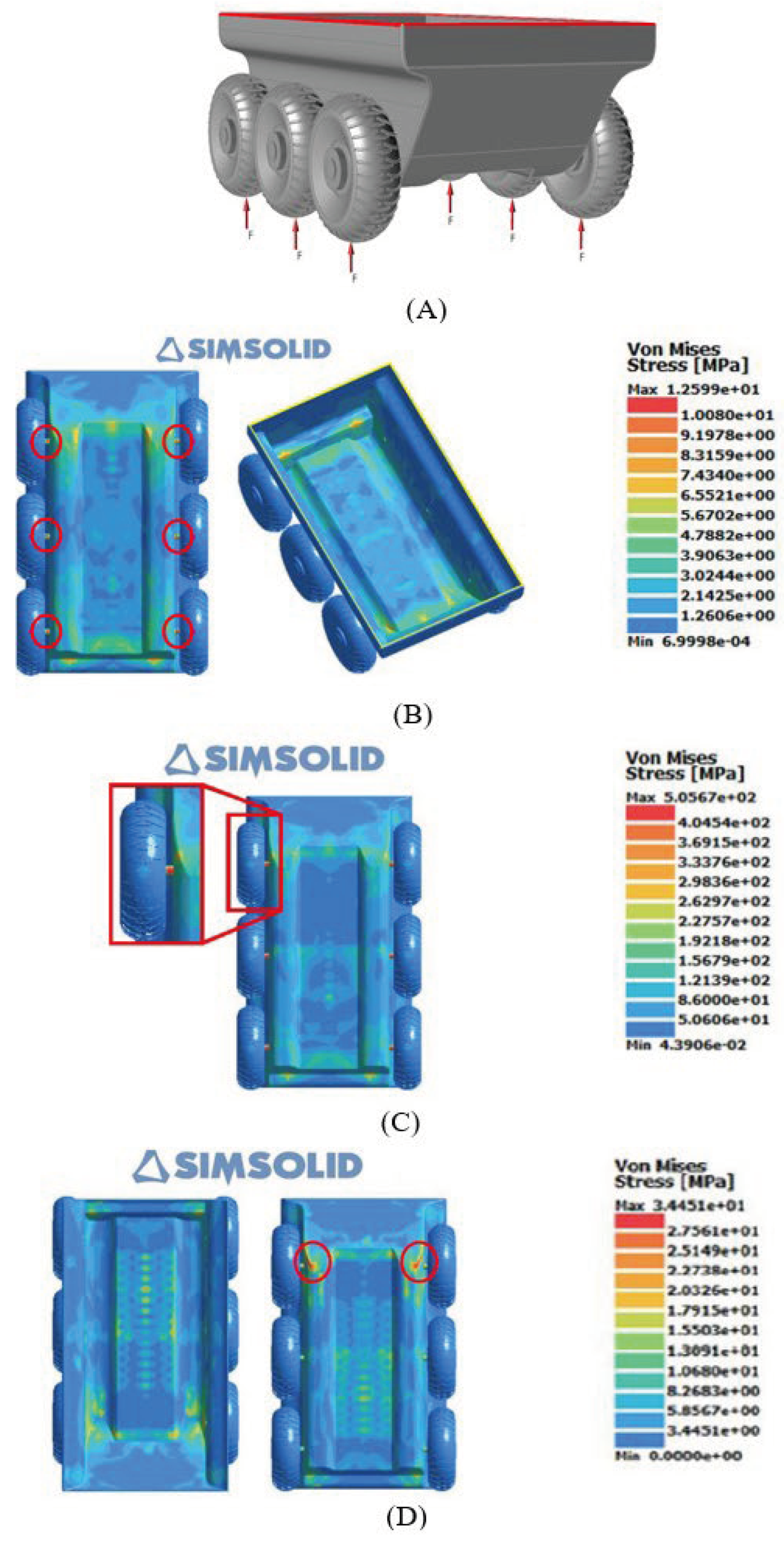
A load that simulates the total weight of vehicle and its payload, is equally distributed and applied on the upwards direction on the bottom of all six wheels, see
Figure 2a). A displacement constrain is applied on all directions at the top edges of the hull, see
Figure 2a).
For this, Altair SimSolid® software is used, in which the following cases are contemplated:
- a)
Vehicle subject to the static loads on the wheels;
- b)
Vehicle subject to a static critical load on the wheels;
- c)
Vehicle subject to the dynamic step loads on the wheels.
For each case the Von Mises stress distribution is obtained to identify the locations of maximum stresses and if these present values below the yield stress of the material.
2.4. Conceptualization and Development
In this phase, the previously defined target specifications are revised and may undergo changes depending on the results of the previous stages. It is essential to establish and respect the defined values considering the constraints inherent to the vehicle’s design, the identified limitations, and the compromise between cost and performance.
3. Results
Based on the methodology and materials previously described the following results are obtained for the conceptual design of the A-UGV here proposed.
3.1. Identified Needs
The identified needs that this vehicle aims to mitigate can be summarized in the following points:
Support and increase capacity in civil and military operations;
Accomplish its mission in order to reduce the risk for all personnel involved;
Ability to operate efficiently on land and in water;
Lightweight and small size vehicle so it can be easily transported and operated;
Ability to equip different types of sensors according to the mission;
Low production, maintenance and operating costs.3.2. Target specifications
3.3. Market Research
The market research analysis allows identifying a selection of some A-UVGs that are designed for similar missions and/or with similar capabilities to those intended for the conceptual A-UGV here proposed. These are presented in
Table 1 alongside with reference to some of their main Conceptualization and development
The design of the hull is inspired on the hulls of the vehicles presented in
Table 1 with focus on the identified need of it being a lightweight and small size A-UGV. Its dimensions are 1050×670×450mm (length-width-height) and 2mm in thickness. The lateral idents allow for the mounting of the six wheels (three on each side) allowing land navigation, rather than tracks since they allow: higher speeds; increased floatability; easier maintenance; and market diversity availability. The wheels are equipped with an internal electric motor, a common off-the-shelf product that does not occupy space inside the hull, that provides greater redundancy and improved independent wheel traction.
Due to the high yield stress values and availability easiness, the following materials are assumed:
Using the methodology and the land mission profile presented in section 2.4.1, after several iterations one obtains for =42.13kg and =7.00kg, a total power =2400W, i.e., 400W per motor. Then, a required energy capacity of the batteries =74 Ah is estimated considering =1.1h, =48V, =0.95, =0.85 and a safety factor of 1.2.
A specific energy density of commercially available Li-ion batteries (VALUE) is considered in the iterative process. Based on the resulting energy requirement and through a brief research, it is determined that a possible battery configuration involves the installation of four 20Ah off-the-shelf Li-ion batteries weighing 5 kg each, with dimensions of 245×160×70mm.
Following, hydrostatic and intact stability analyses are conducted as described in
Section 2.4.2. Considering a water level height of 0.2m it is then verified that the intact stability of the vehicle is positive, with a metacentric height of 0.360m.
Next, using Altair
® HyperWorks
TM with the AcuSolve
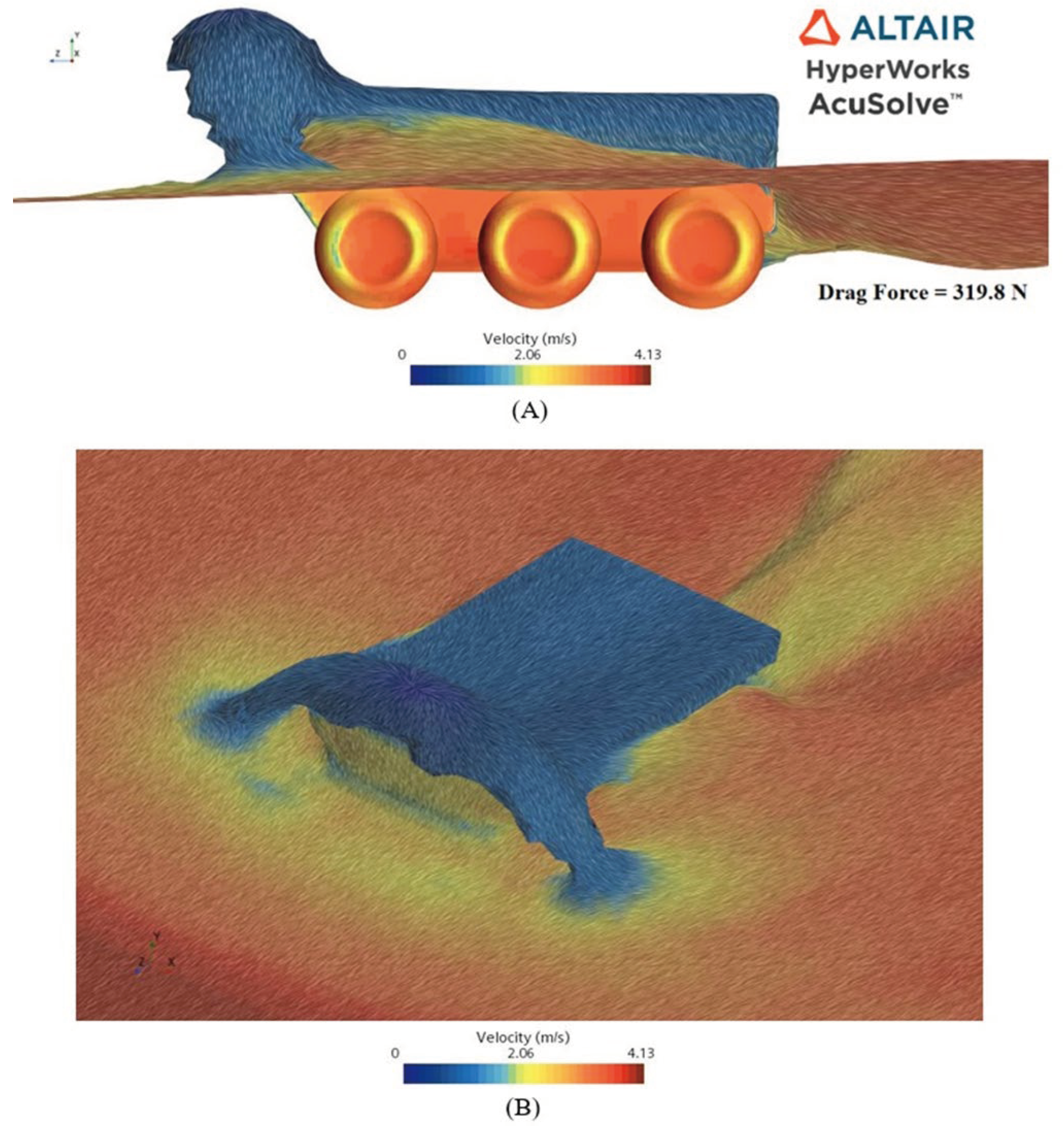
TM solver, the 3D pressure and velocity distributions as well as the drag force of the vehicle is estimated, see
Figure 1, using the methodology described in
Section 2.4.3.
From
Figure 1, it is possible to verify a decrease in the speed flow in front of the vehicle. This behavior is due to the interaction of the fluid with the hull of the vehicle which, due to its configuration, leads to the creation of a wave, a splash effect, increasing the pressure distribution exerted by the flow in front of the vehicle. Also, due to the design created at the rear of the vehicle, there is a decrease in the pressure field leading to a decrease of speed in that region.
By multiplying the total drag force (at maximum speed) of ~320 N, see
Figure 1A, by the maximum speed of the vehicle in water, one obtains a maximum power required for the water motor of approximately
=1310W.
Considering the water mission profile presented in
Section 2.4.3, the required energy capacity of the batteries may be estimated using Equation (2) considering: the previously estimated required powers for the land and water motors (2400W and 1310W, respectively),
=1.75h,
=48V,
=0.95 and
=0.85. By additionally assuming a safety factor of 1.2 one obtains a total required energy capacity
=77Ah which is available assuming the 80Ah battery configuration previously established.
3.4. Static and Dynamic Structural Analysis
To assess the structural integrity of the vehicle, static and dynamic structural analyses, see
Section 2.4.4, are carried out on the conceptual vehicle with the boundary condition illustrated in
Figure 2A.
Figure 2.
– Static and dynamic analysis: (A) Boundary conditions; (B) Static stress results; (C) Critical load stress results; (D) Dynamical step load stress results.
Figure 2.
– Static and dynamic analysis: (A) Boundary conditions; (B) Static stress results; (C) Critical load stress results; (D) Dynamical step load stress results.
Figures 2B through (D) illustrate the Von Misses stress distribution results considering: (B) a total applied static load of 500N; (C) the critical static load; and (D) a total applied dynamic step load of 500N.From
Figure 2B, it is possible to observe that the points where the highest stresses are located are some edges and vertices of the hull structure and the shafts that connect the wheels to the hull. However, the maximum stress to which the structure is subjected is approximately 12.6MPa located in the shafts. Given that the yield stress of the shaft material is 503MPa, it is verified that the material can withstand the imposed static load.
To locate the first point of failure, the applied load is gradually increasing, until the maximum stress value is greater than that of the yield stress. It is observed that the shaft is the first component to fail, see
Figure 2C, as it presents a stress of approximately 506MPa (>503MPa). However, this failure only occurs when the applied total load reaches approximately a critical value of 34.5kN which is considerably well above the static and dynamic applied loads.
Similarly to the static load case, from
Figure 2D, it is possible to observe that the points with the highest stresses are located in some edges and vertices of the hull structure and the shafts that connect the wheels to the hull. However, as the maximum stress to which the structure is subjected is approximately 27.5MPa located in the shafts (<503MPa), it is verified that the material can withstand the imposed dynamic step load.
These results suggest further research regarding the minimization of the mass of the vehicle and/or the use of materials with lower values of yield stress which are usually less expensive.
3.5. Final Specifications
The last step of conceptual development is the reconsideration of the specifications initially established. Of the initially imposed specifications/requirements, the only change is the increase in vehicle weight to 50kg. The reasons that justify this change are the fact that it allows a greater payload, maintaining the number of batteries required with an inherent cost of decreasing the autonomy. This alteration had no negative impact on the fulfillment of the remaining identified needs, being possible to maintain the maximum speed, stability conditions and acceptable waterline level.
Thus, the final specifications of the vehicle are:
Maximum weight 50kg;
Land traction 6×6;
Maximum land speed of 20km/h;
Dedicated means of displacement in the water;
Maximum water speed of 8kts;
Buoyancy and stability in water;
Autonomy greater than 1h;
4 Li-ion batteries (80Ah);
Hull made of resistant material.
Considering these final specifications, an initial estimate of the production cost of the vehicle contemplating the materials considered in the structural analysis and off-the-shelf components, includes the following items: i) 1200€ for batteries; ii) 720€ for land propulsion wheels (motor and shaft included); iii) 135€ for a water propulsion motor; iv) 300€ for a remote control; v) 80€ for telemetry components; vi) 100€ for electric cables; vii) 1000€ for carbon reinforced fiber; viii) 300€ for the mold of the hull; ix) 1000€ for man labor. This leads to a total estimate of 4835€.
Note that the highest cost is related to batteries and labor. Even so, this initial estimate is below the maximum limit of 5000€ initially defined for the vehicle.
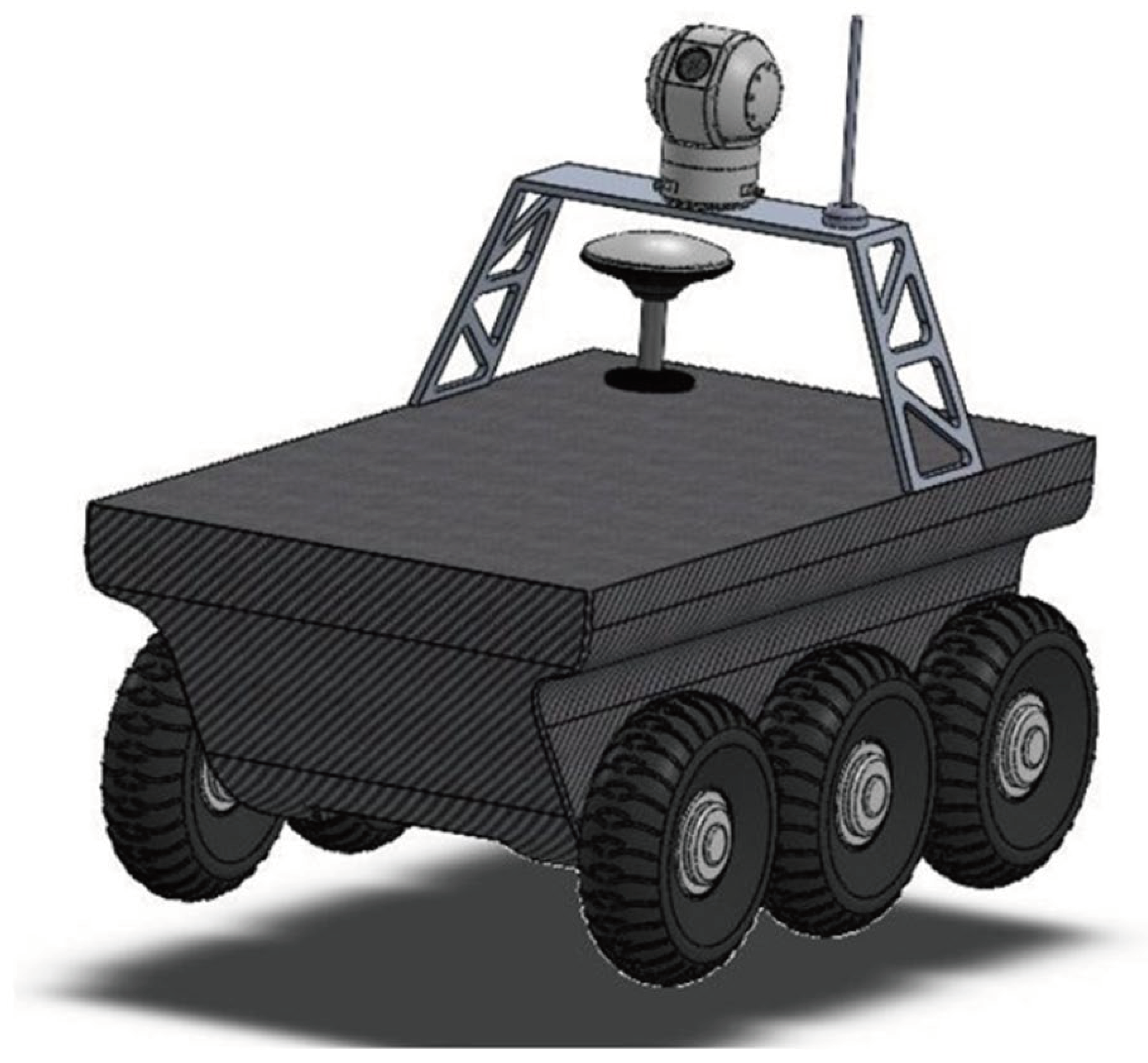
In
Figure 3 is illustrated a rendering of the CAD model of the conceptual A-UGV equipped with some sensors revealing what this vehicle may become in a near future.
4. Final Remarks
It is considered that the conceptual design project of the proposed vehicle is successfully achieved leading to a fully electric, modular, portable, low-cost A-UGV capable of operating in multi-operational scenarios. The resulting specifications allows the future continuity of this project into a detailed development phase, in which the control and sensor topics must be addressed, allowing the development, construction, and testing of a prototype wherein. New challenges will arise originating new design iterations and consequently allowing for the fine tune of the final specifications of the vehicle.
Author Contributions
HP: Writing – original draft, Writing – review & editing, Conceptualization, Methodology, Project administration, Supervision, Visualization. JPBL: Writing – original draft, Writing – review & editing, Formal analysis, Investigation, Software. AMA: Writing – review & editing, Conceptualization, Methodology, Formal analysis, Investigation, Software. RP: Writing – review & editing, Formal analysis, Investigation, Software. FR: Writing – review & editing, Funding acquisition. DS: Writing – review & editing, Funding acquisition. FA: Writing – review & editing. DMSA: Writing – review & editing. NMMM: Writing – review & editing. All authors contributed to manuscript revision, read, and approved the submitted version.
Data Availability Statement
The raw data supporting the conclusions of this article will be made available by the authors, without undue reservation, upon request.
Acknowledgments
This work was supported by FCT, through IDMEC, under LAETA, project UIDB/50022/2020. This work was further supported by FCT through: PhD grant 2021.06353.BD; Institute for Systems and Robotics (ISR), under Laboratory for Robotics and Engineering Systems (LARSyS) project UIDB/50009/2020; project PCIF/MPG/0156/2019 FirePuma; and COPELABS, University Lusófona project UIDB/04111/2020. The authors further acknowledge Althima-Engineering Software Solution, Lda and Altair Engineering Inc. for providing an Altair license allowing for the development of the CAE simulation conducted during this work.
Conflicts of Interest
The authors declare no conflicts of interest.
References
- Tesla, N. (1898). Method of an Apparatus for Controlling Mechanism of Moving Vessels or Vehicles. U.S. Patent, No. 613809, Art. U.S. Patent No. 613809.
- Wickersham, E. E. (1922). Land Torpedo. U.S. Patent, No. 140798, Art. U.S. Patent No. 1407989.
- Czapla, T. , & Wrona, J. (2013). Technology Development of Military Applications of Unmanned Ground Vehicles BT. In A. Nawrat & Z. Kuś (Eds.), Vision Based Systems for UAV Applications (pp. 293–309). Springer International Publishing. [CrossRef]
- Darrach, B. (1970). Meet Shaky, the first electronic person. Life Magazine, 69 (21), 58–68.
- Kuipers, B. , Feigenbaum, E. A., Hart, P. E., & Nilsson, N. J. (2017). Shakey: From Conception to History. AI Magazine, 38(1), 88–103. [CrossRef]
- Flynn, A. M. (1985). Redundant Sensors for Mobile Robot Navigation. Technical Report 859.
- Moravec, H. P. (1983). The Stanford Cart and CMU Rover. Robotics Institute, Carnegie-Mellon, Technical Report.
- Murphy, D. W. , & Bott, J. P. (1995). The AirMobile Ground Security Surveillance System (AMGSSS). Unmanned Systems, 13 (3).
- Metz, C. D. , Everett, H. R., & Myers, S. (1992). Recent Developments in Tactical Unmanned Ground Vehicles. Proceedings of AUVS-92.
- Seetharaman, G. , Lakhotia, A., & Blasch, E. P. (2006). Unmanned vehicles come of age: The DARPA grand challenge. Computer, 39 (12), 26–29. [CrossRef]
- Zhang, T. , Li, Q., Zhang, C., Liang, H., Li, P., Wang, T., Li, S., Zhu, Y., & Wu, C. (2017). Current trends in the development of intelligent unmanned autonomous systems. Frontiers of Information Technology & Electronic Engineering, 18(1), 68–85. [CrossRef]
- LeCun, Y., Bengio, Y., & Hinton, G. (2015). Deep learning. Nature, 521(7553), 436–444. [CrossRef]
- He, M. , Yue, X., Zheng, Y., Chen, J., Wu, S., Heng, Z., Zhou, X., & Cai, Y. (2023). State of the art and future trends in obstacle-surmounting unmanned ground vehicle configuration and dynamics. Robotica, 1–23. [CrossRef]
- Liu, Q. , Li, Z., Yuan, S., Zhu, Y., & Li, X. (2021). Review on Vehicle Detection Technology for Unmanned Ground Vehicles. In Sensors, 21 (4). [CrossRef]
- Ni, J. , Hu, J., & Xiang, C. (2020). A review for design and dynamics control of unmanned ground vehicle. Proceedings of the Institution of Mechanical Engineers, Part D: Journal of Automobile Engineering, 235(4), 1084–1100. [CrossRef]
- Ruslan, N. A. I. , Amer, N. H., Hudha, K., Kadir, Z. A., Ishak, S. A. F. M., & Dardin, S. M. F. S. (2023). Modelling and control strategies in path tracking control for autonomous tracked vehicles: A review of state of the art and challenges. Journal of Terramechanics, 105, 67–79. [CrossRef]
- US Army. (2008). Testing of Unmanned Ground Vehicle (UGV) Systems. Test Operation Procedure, US Army (TOP 2-2-54).
- Marinha Portuguesa. (2021). DEM 2018 REV 2021. Diretiva Estratégica Da Marinha 2018 - Revisão 2021. https://www.marinha.pt/conteudos_externos/Diretiva_Estrategica_da_Marinha/DEM_2018_REV2021/.
- San-Miguel-Ayanz, J. , Oom, D., Artes, T., Viegas, D. X., Fernandes, P., Faivre, N., Freire, S., Moore, P., Rego, F., & Castellnou, M. (2020). Forest fires in Portugal in 2017. Science for Disaster Risk Management. [CrossRef]
- Montiel, C. , & Kraus, D. T. (2010). Best practices of fire use: prescribed burning and suppression: fire programmes in selected case-study regions in Europe. In European Forest Institute.
- Ulrich, K. , Eppinger, S., & Yang, M. C. (2020). Product Design and Development. McGraw Hill, 7th Ed.
- Evans, J. H. (1959). Basic Design Concepts. Journal of the American Society for Naval Engineers, 71(4), 671–678. [CrossRef]
- NATO. (2015). NATO AAP-20 - Nato Programme Management Framework (NATO Life Cycle Model).
- Jones, E. , & Childers, R. (2001). Contemporary College Physics (3rd Ed). McGraw-Hill Education.
- Moore, C. S. (2010). The Principles of Naval Architecture Series: Intact Stability. The Society of Naval Architects and Marine Engineers.
- Apanovitch, V. (2021). The Method of External Finite Element Approximations (I. Published, Ed.).
|
Disclaimer/Publisher’s Note: The statements, opinions and data contained in all publications are solely those of the individual author(s) and contributor(s) and not of MDPI and/or the editor(s). MDPI and/or the editor(s) disclaim responsibility for any injury to people or property resulting from any ideas, methods, instructions or products referred to in the content. |
© 2024 by the authors. Licensee MDPI, Basel, Switzerland. This article is an open access article distributed under the terms and conditions of the Creative Commons Attribution (CC BY) license (http://creativecommons.org/licenses/by/4.0/).
