1. Introduction
Recently, there has been a significant increase in the number of infrastructure for producing power utilizing renewable energy sources for stable power systems due to the risk of depletion and harmful environmental impacts of traditional energy sources [1, 2]. Renewable energy sources-based power systems have developed dramatically due to the substantial growth in energy demands, which are essential to the survival of humanity, and the demand for more effective energy generation, transmission, and distribution. On the other hand, renewable energy-based power plants, such as those powered by solar and wind, are often located relatively far away from load centers [
3]. Specifically, offshore wind-powered power plants are situated at great distances from the mainland. When it comes to sending electrical power generated far away from the mainland to load centers over tremendous distances or offshore, HVDC technology is crucial [4-8]. HVDC technology is essential to today's power systems because of characteristics including adaptability, efficiency in power transmission, affordable and technical advantages, eco-friendly, narrow transmission line losses, appropriate for high power large-scale, high-power transmission throughout extensive distances, combining asynchronous power systems, submarine cable connection, defense to deviations in phase angle, frequency, impedance, or voltage, sustaining standalone frequency and generator management especially when compared to conventional HVAC power systems [5-7, 9-13]. It is clear from the aforementioned characteristics that HVDC technology will serve a crucial role in the present-day power networks of the coming decades. HVDC technology has a significant presence in today's power systems, which is overwhelmingly due to power electronics-based converter technologies. Put another way, the fast advancement of semiconductor-based power electronics technology has made it possible for HVDC technology to be a significant component of modern power systems. The converter units located at the connection points of HVDC technology are frequently centered on voltage source converters (VSC) or line commutated converters (LCC) [
14]. Nonetheless, multi-level converter systems will now mostly be utilized in HVDC technology owing to recent improvements in semiconductor-based power electronics technology. Predominantly owing to conventional DC-DC converter systems that depend on power electronics components, HVDC technology is becoming increasingly widespread in power systems.
In HVDC technologies, multi-level converter systems have gained popularity recently in addition to conventional DC-DC converter architectures. Specifically, as a consequence of having power quality enhancement, reliability, high efficiency, lower power switch rating, excellent output capacity, substantial modularity, straightforward scaling, transformerless operating capabilities, tolerant of failures, utilizing typical elements, extremely readily accessible, and straightforward operation system [14-22] valuable characteristics, MMC [23, 24] technology which is a multi-level structure has attracted the interest of a large number of researchers studying HVDC power systems applications. In power systems, conventional MMC technology that has been established in the literature can be implemented as an inverter station (DC-AC) as well as a rectifier station (AC-DC). MMC technology is efficiently employed in numerous applications, including HVDC power transmission systems [
25], static synchronous compensator (STATCOM) utilizations [26, 27], DC-DC transformation systems [28, 29], battery energy storage systems [30, 31], developing electric ships [
32], variable-speed drives for motors [33, 34], active power filters [
35], electric vehicles [
36], solar photovoltaic systems [37-39], because of its beneficial advantages.
Due to its increasing popularity, DC-DC MMC technology which is accomplished through utilizing conventional MMC technology as a reference has drawn the curiosity of many researchers. In DC-DC MMC topologies, some topologies are isolated by a transformer between the primary and secondary sections of designs, as well as non-isolated topologies where no transformer is used between the primary and secondary sections of designs. DC-DC MMC technology provides excellent results, particularly in the integration of modern asynchronous HVDC power systems and the integration of new-generation HVDC power systems with existing asynchronous HVAC power systems. Many DC-DC MMC layouts have been developed for HVDC power system interconnections regarding classical MMC technology. In particular, DC-DC MMC configurations serve a vital role in interconnecting multi-level HVDC power systems that have various voltage levels [
40]. Numerous DC-DC MMC topologies have been published in the literature as a result of their adaptable and modular architecture.
Table 1 presents the notable achievements and novel characteristics associated with several DC-DC MM topologies that have been identified in the literature.
In cases where it comes to combining HVDC power networks having different voltage levels and incorporating them with already-existing asynchronous HVAC power networks, DC-DC MMC technology is critically important. The foregoing scenario is substantially supported by
Table 1 and multiple noteworthy DC-DC MMC configurations discovered in the literature are nevertheless included in
Table 1. To successfully integrate two asynchronous HVDC power grids, a unique DC-DC MMC design is introduced in this study. The operation of the fundamental nature, simulation-based parameter records, and mathematical analysis of the relevant topology have all been thoroughly analyzed.
2. MMC Technology
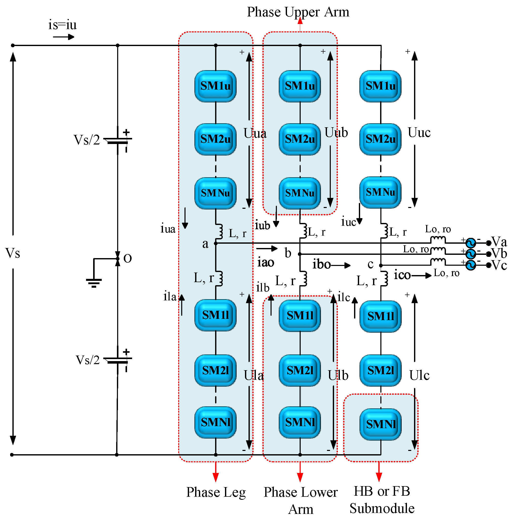
The conventional MMC topology initially put forward in a German patent by Prof. Marquardt in 2001 [
23], is illustrated in
Figure 1. The aforementioned patent illustrates the inductances within each arm, the half-bridge (HB) and full-bridge) FB) submodules (SMs), and the DC to three-phase converter structure including a sequence of interconnected SMs. Regarding many applications, the conventional MMC architecture provides the ability to function either as a rectifier (AC-DC) or as an inverter (DC-AC). Each phase in the traditional MMC design is made up of two arms: the upper arm and the lower arm, as seen in
Figure 1. An arm inductor (L, r) and HB or FB SMs connected in series constitute each upper arm and lower arm. A branch leg originates from each phase's midpoints (a, b, and c) and connects the system's three-phase AC terminals (Va, Vb, and Vc) via a phase inductor (Lo, ro). In other words, the design's AC terminal is linked to the center of every phase, meanwhile, the DC terminal is linked between the upper and lower arms of the phases. The appropriate AC and DC currents are produced by the regulated voltages every single arm produces at individual endpoints in conjunction with the appropriate DC and AC design voltages.
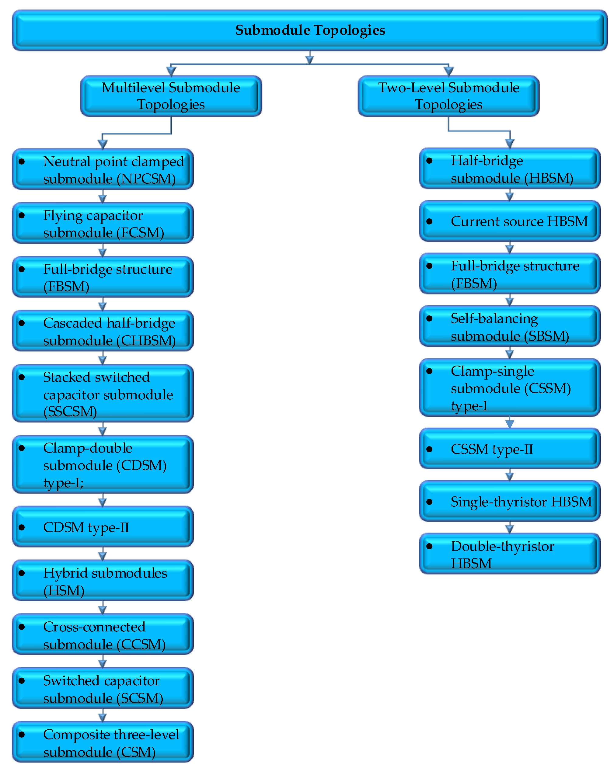
In MMC concepts, the SM structure is extremely critical. From the time the MMC structure was originally presented in the literature till the present day, multiple SM topologies have been developed by many researchers. As demonstrated in
Figure 2, SM structures can be categorized into two main groups according to the output voltage level: single-source two-level SM topologies and multiple-source multilevel SM topologies [
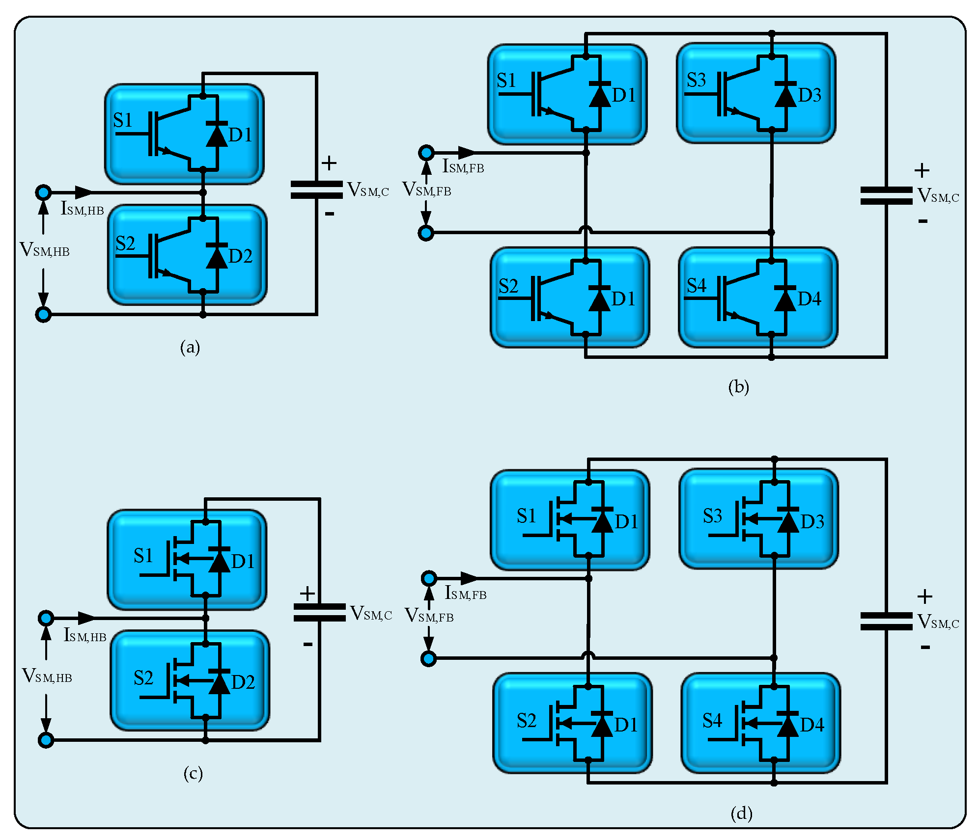
22]. Undoubtedly, one of the primary explanations for the recent increase in curiosity regarding MMC technology is the significant advancements in semiconductor technology. Given that SM structures, which are the backbone of MMC technology, consist of semiconductor-based power switching elements. In particular, owing to their outstanding characteristics, which include their capacity to operate at more substantial temperatures, reduced switching losses, and high switching capabilities metal oxide semiconductor field effect transistors (MOSFETs) and insulated gate bipolar transistors (IGBTs) power switching components based on silicon carbide and gallium nitride are utilized in SM architectures of MMC designs. HB topology is a unipolar semiconductor-based circuit structure that is most frequently utilized in SM circuits because of its straightforward construction. HBSM has lesser power losses as a result of its straightforward structure. Incorporating two HBSMs and one floating capacitor, the FBSM structure is a semiconductor-based circuit structure. The FBSM structure provides effective defenses against DC fault current. However, there are larger power losses due to the fact that there are more semiconductor-based power-switching devices than there are in the HBSM structure [
22].
Figure 3 illustrates the SM structures that researchers most frequently utilize in MMC architectures. IGBT-based HBSM and FBSM architectures are depicted in
Figure 3a and
Figure 3b, correspondingly. The MOSFET-based HBSM form is depicted in
Figure 3c, while the MOSFET-based FBSM architecture is presented in
Figure 3d.
4. Operational Principle and Simulation Analysis of the DC-DC MMC Topology
The suggested DC-DC MMC design's key objective is to integrate HVAC and HVDC asynchronous networks with various voltage levels. This is the design's fundamental operation concept. In accordance with the aforementioned desire, two approximately real-life asynchronous networks have been incorporated into the present investigation utilizing a simulation environment, as shown in
Figure 8. The system that has been presented in this research has a primary end featuring a voltage level of 300 kV and a power of 210 MVA, and a secondary end featuring a voltage level of 200 kV and a power of 190 MVA. The rectifier station that converts HVAC voltages into HVDC voltages is positioned on both the primary as well as the secondary side of the system. These rectifier stations' fundamental objective is to assist with making sure that the suggested system integrates with existing HVAC networks. The primary and secondary sides of the proposed DC-DC MMC system receive network voltages from rectifier stations, which convert HVAC voltage to HVDC voltage.
The processes of transformation and transfer operate underneath the guidance of the control system which is illustrated in
Figure 9. The design variables associated with the suggested system have been determined which can be witnessed in the control system, the corresponding values have been supplied into the framework with the help of a filtering mechanism. For this data transmission, current, voltage, and power control mechanisms based on Proportional-Integral-Derivative Controllers (PID Controller), Clarke Transformation mechanism, and Phase Locked Loop structure have been utilized. In the stable αβ framework, the equilibrium two-phase orthogonal parts are obtained by applying the Clarke transformation to the equilibrium three-phase elements of HVAC Grid-1 and HVAC Grid-2 in the abc referencing structure of the proposed topology. Furthermore, the Clarce Transformation structure can generate the variables α, β, and 0 by computing the Clarke transformation of the three-phase variables a, b, and c. The PLL module simulates a PLL closed-loop control framework, that utilizes an inner frequency generator for monitoring the frequency and phase of a sinusoidal wave. The inner generator frequency is modified by the controller in order to maintain a phase shift of zero. The controller system's d-q transformation module utilizes the α and β variables which are obtained from Clarke Transformation for determining the quadratic axis (q) and direct axis (d) parameters. The signal computation section determines parameters in accordance with the values of the filter mechanism that the system controller implements. PID-based current, voltage, and power control units customize the parameters that are needed to ensure the suggested DC-DC MMC system behaves reliably and steadily.
The suggested DC-DC MMC is simulated in the simulation environment in order to demonstrate the system's effectiveness and functionality.
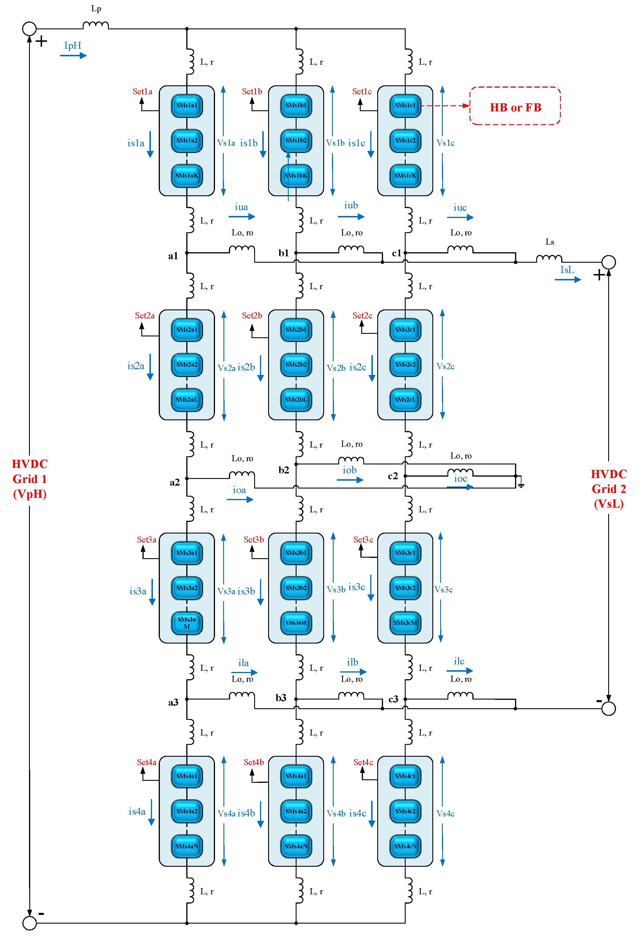
Table 2 summarizes the parameters of the proposed DC-DC MMC topology which is given in
Figure 4. The following section presents the outcomes of the simulation obtained by employing the suggested design regarding the data presented in
Table 2. In the present study, the individual phase disposition pulse width modulation (PD-PWM) technology has been applied for controlling power switching in SM sets of architecture. GBT power switches have been employed in the HBSM architecture of the suggested design given that they have lower switching losses, a higher switching frequency, and provide superior outcomes at higher voltage levels.
The suggested research system's simulated waveforms are displayed in
Figure 10,
Figure 11 and
Figure 12.
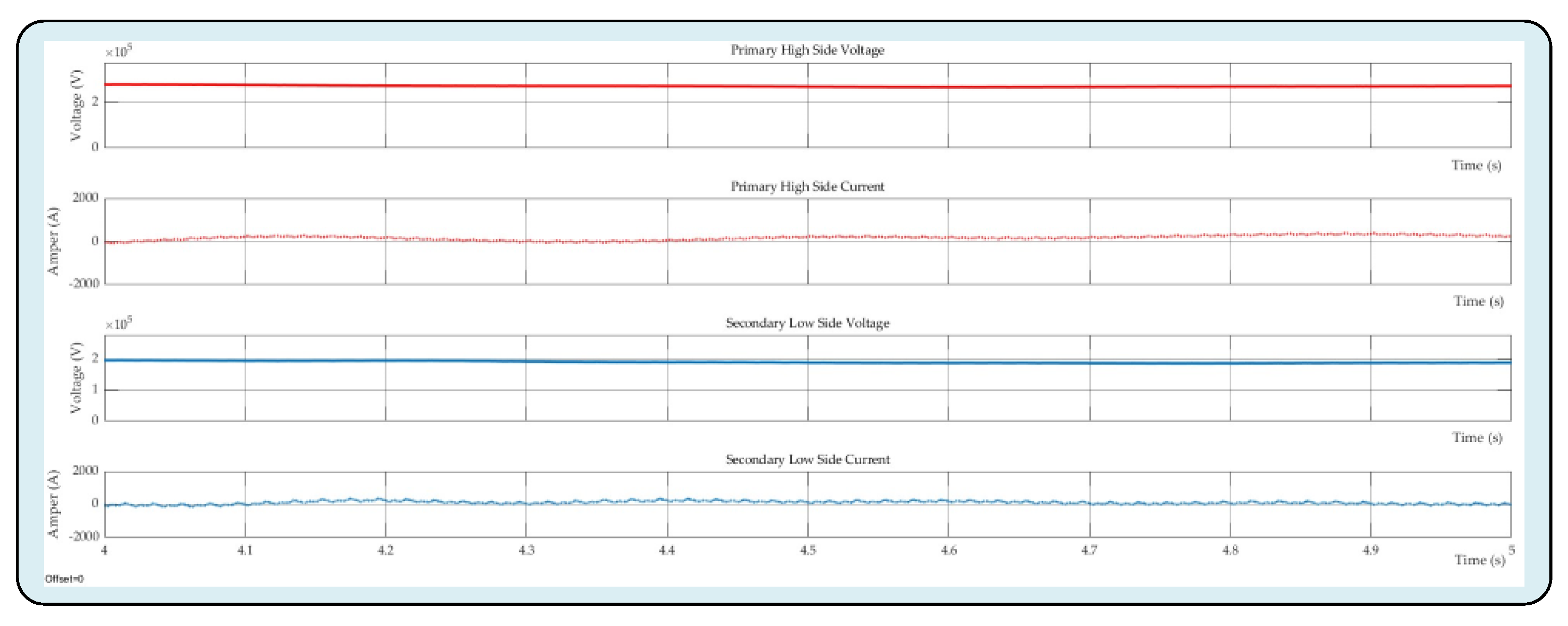
Figure 10 illustrates the primary side voltage (higher voltage level), primary side current, secondary side voltage (lower voltage level than the primary side), and secondary side current waveforms of the proposed DC-DC MMC design respectively. The voltage level of the primary side is 262 kV, whilst the secondary side is 184 kV, as demonstrated in
Figure 10. For the aforementioned voltage levels, the corresponding primary side and secondary side currents are 768 A and 1355 A, respectively. As can be seen in the mathematical analysis given in
Section 3.2, voltage and current expressions consist of both AC and DC components. This situation causes some fluctuations, albeit at low levels, especially in the primary and secondary current waveforms of the system. The aforementioned findings indicate that an equilibrium power transfer between two power networks is provided by the DC-DC MMC design.
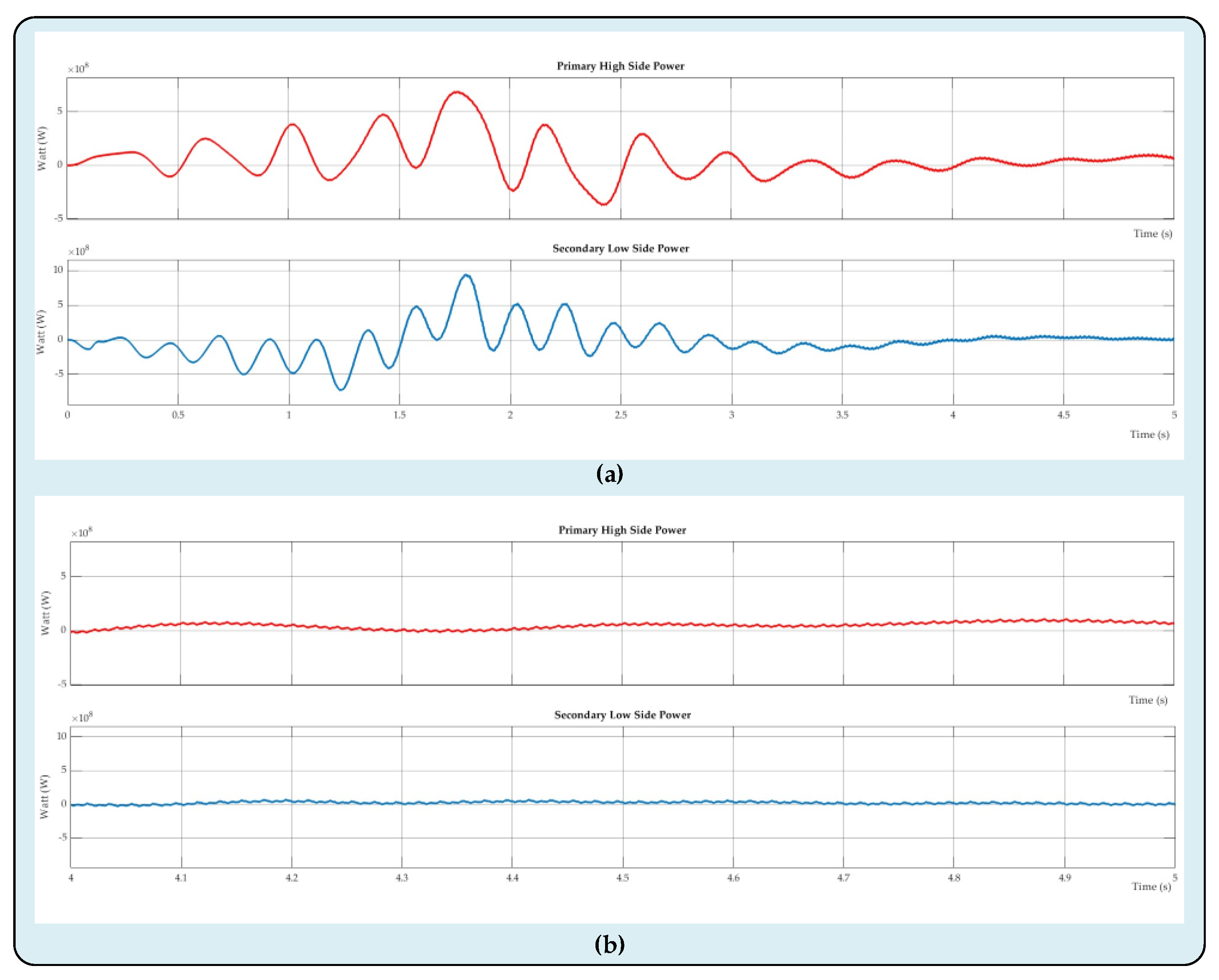
The proposed DC-DC MMC design's bidirectional primary and secondary power waveforms are depicted in
Figure 11. The secondary side's power value has been determined at 230 MW, whilst the primary side's power value was 194.2 MW. Power fluctuations are seen while looking at the power diagrams, particularly because of the AC components included in the primary and secondary currents. On the other hand, it is evident from the power waveforms that a more steady power flow starts about three seconds after the system boots up.
Figure 11a exhibits all of the primary and secondary power waveforms;
Figure 11b shows these power waveforms magnified. Consequently, it is visible from analyzing the primary and secondary waveforms that the suggested DC-DC MMC architecture successfully facilitates power transfer between two asynchronous HVDC power grids.
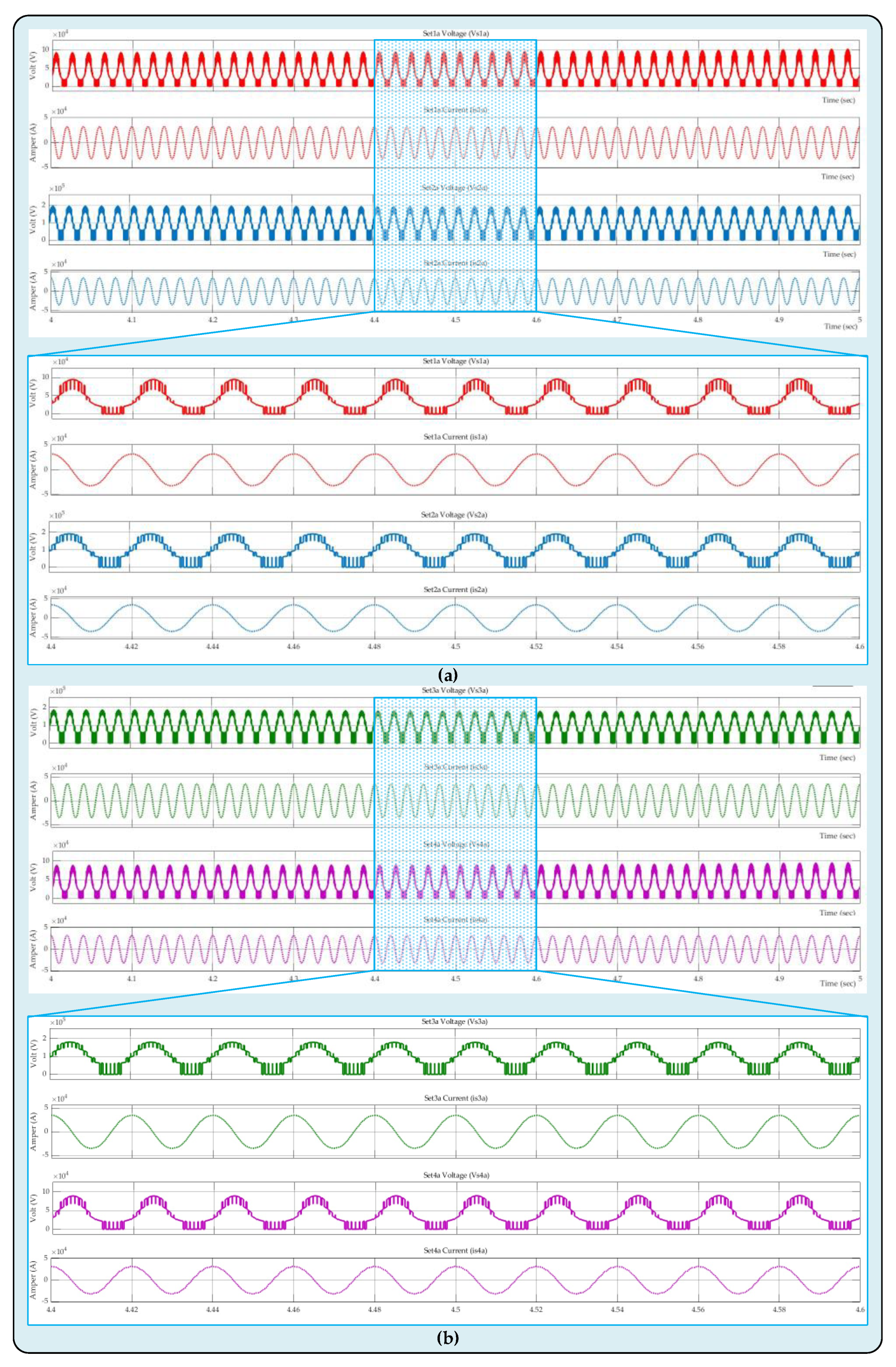
The voltage across the four SM sets in system arm-a as well as the currents flowing through the appropriate SM sets have been shown in
Figure 12. The novel configuration that has been suggested has three arms, each of which has four SM sets, as shown in
Figure 4. The PD-PWM approach, which operates based on reference signals with a 120-degree phase difference between each arm, has been employed for switching the power switches. To prevent the study in consideration from being too long, voltage and current waveforms of the SM sets on the arm-a have been included in this study. The waveforms for voltages and currents of the set1a and set2a SM sets have been demonstrated in
Figure 12a, and the waveforms for the set3a and set4a SM sets have been displayed in
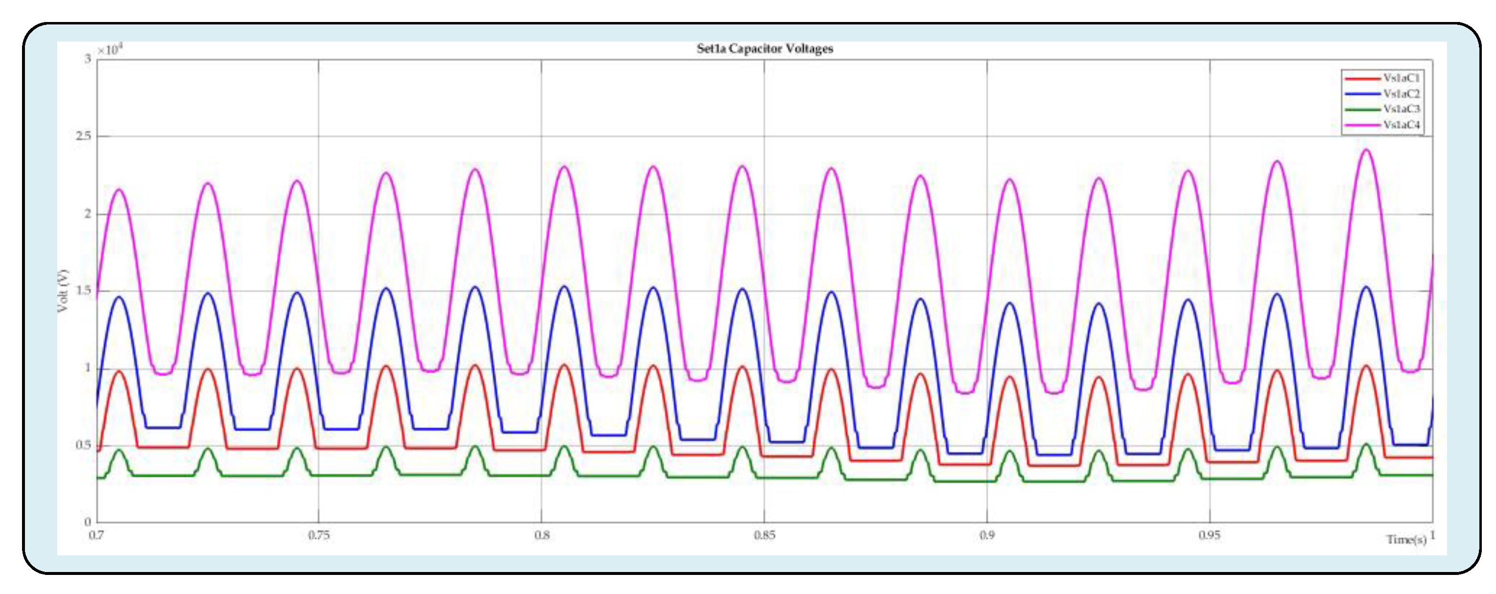
Figure 12b. Since four HBSMs have been used in SM sets, five distinguished voltage levels have been obtained. It is clear from examining the data produced by the pertinent voltage and current waveforms that the suggested architecture and associated control mechanisms operate admirably. The waveforms of the capacitor voltages in the set1a SM set of the design's arm-a have been presented in
Figure 13. It is readily apparent that an efficient capacitor voltage balancing has been accomplished when glancing at the waveforms of the capacitor voltages in
Figure 13. The system's arm-a data illustrates that the innovative DC-DC MMC architecture that has been suggested successfully integrates two asynchronous power networks.
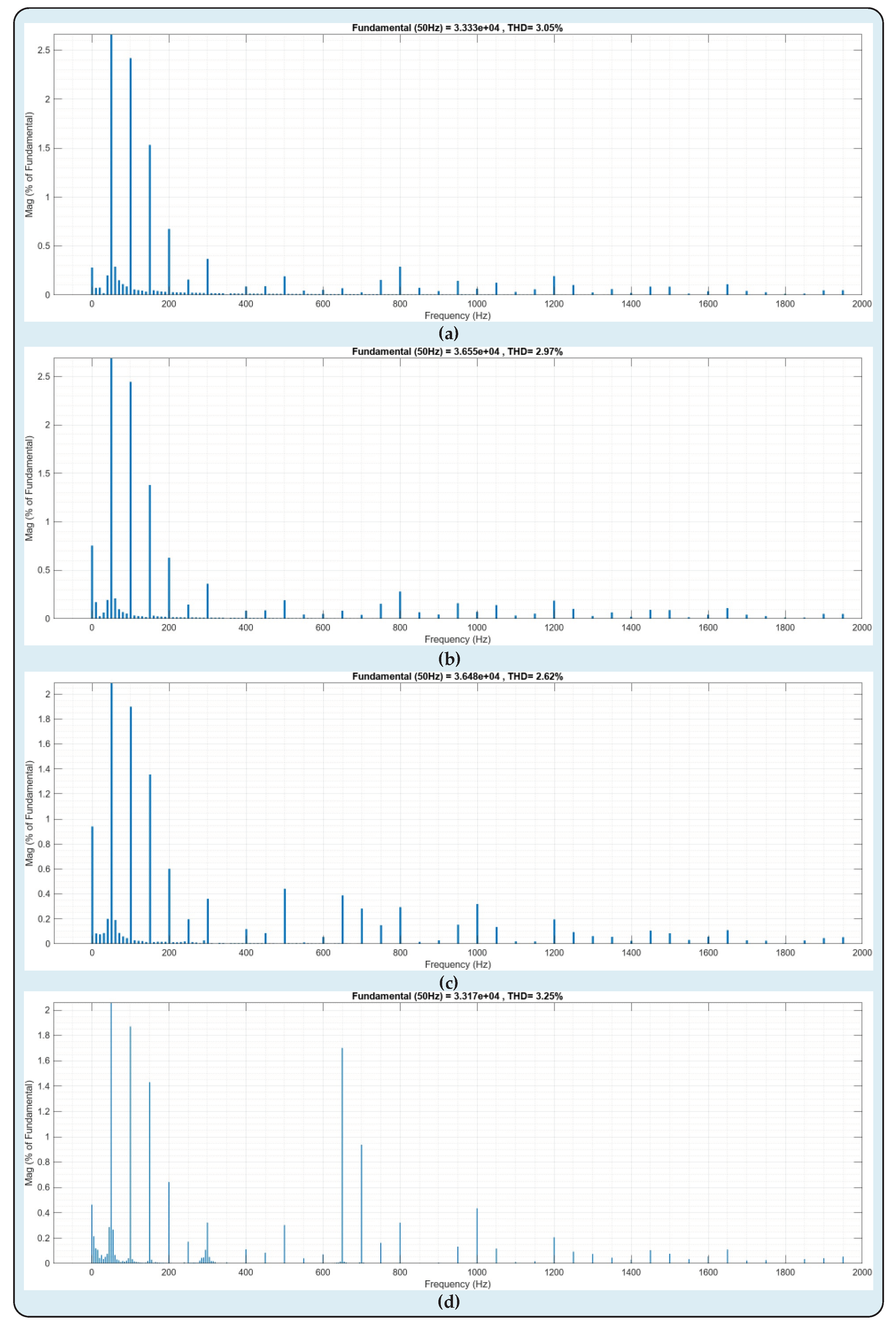
The Fast Fourier Transform (FFT) analysis of the voltage and current waveforms of the SM sets of the a-arm and the current and voltage waveforms of the primary and secondary sides of the suggested DC-DC MMC converter architecture have been depicted in
Figure 14,
Figure 15 and
Figure 16. In cases where transforming discrete impulses from the time domain to the frequency domain, the discrete Fourier transform is implemented and improved upon with FFT. The phases, structure of the frequencies, as well as additional characteristics of the electrical signal, are all revealed by FFT estimations. Electrical facilities' voltage, current, and power characteristics are supposed to follow a sine wave in power networks. Nevertheless, is challenging for the current and waveforms in electrical networks to remain unadulterated sinusoidal owing to the expanding variety of modern industrial loads that are semiconductor-based, and the power electronics-based converter systems located in many power systems presently. Therefore, the shape of a sine wave is no longer the sole pattern that is seen in the waveforms of power system network parameters. Harmonics are components of electrical power networks that deform waveforms of current and voltage parameters. It is expected that harmonic distortions be observed to occur more frequently, particularly in power systems with substantial involvement from power electronics-based converter systems. Nevertheless, thanks to their such as controllability and flexibility features, it is unavoidable that these types of structures are going to be employed in the modern power systems of the present day. In other words, these power electronics-based approaches are necessary for today's modern power systems to adapt optimally to modern load characteristics. Nonetheless, the aforementioned potential harmonic distortions can be minimized providing these designs which are essentially expected to be utilized in present-day power systems are developed in the most efficient and technologically advanced manner conceivable given their operational characteristics. These structures have superior control techniques that can mitigate harmonic distortions in addition to their optimal architecture. Considering account of all of the aforementioned information, the DC-DC MMC architecture presented in this research has been developed with the objective of offering ideal solutions for the optimization of today's contemporary power systems. The highest-performing FFT analyses which are carried out using the fundamental grid frequency (50 Hz) for this scenario are shown in
Figure 14,
Figure 15 and
Figure 16. In
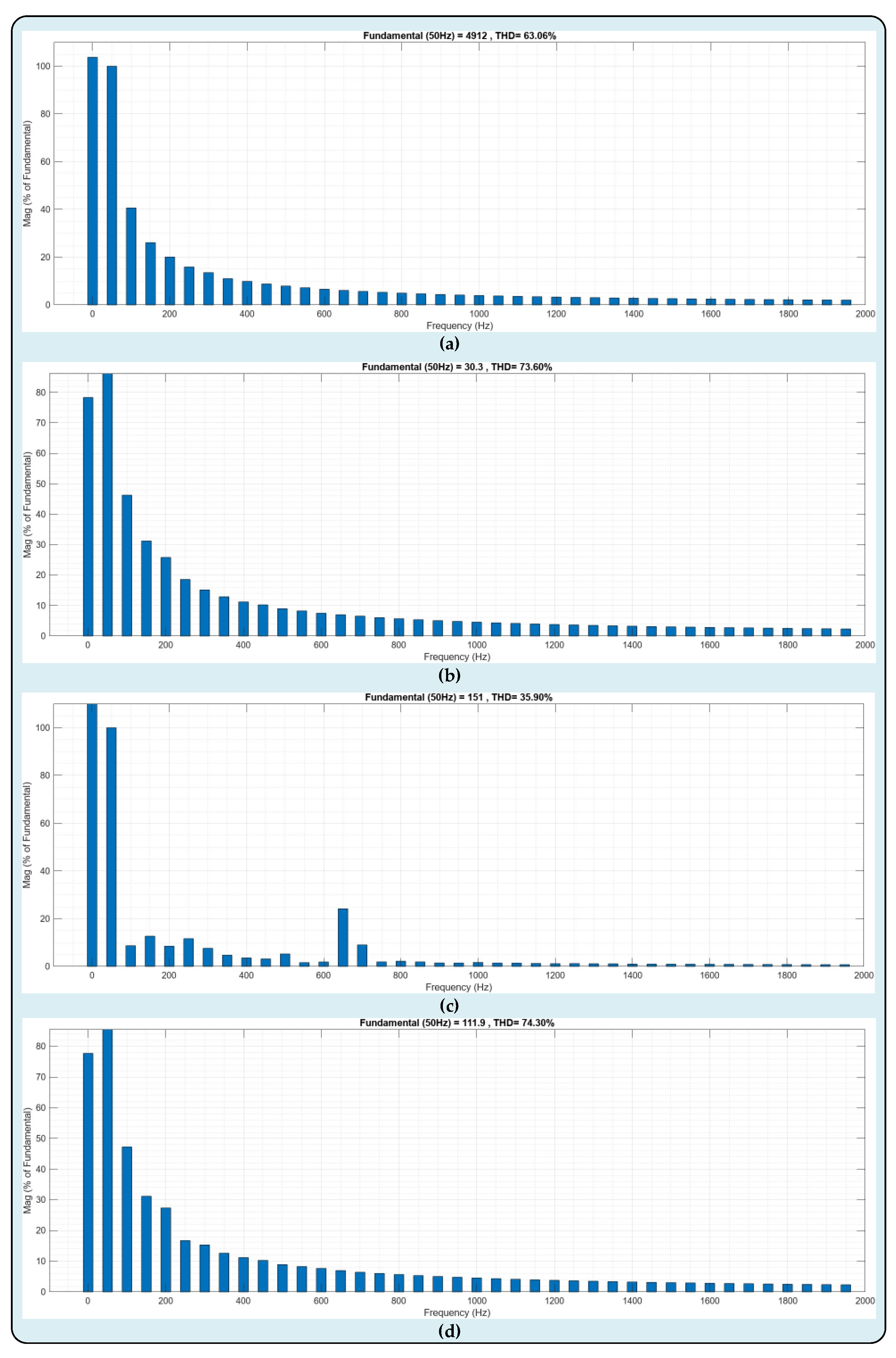
Figure 14, the FFT analysis of the voltage and current waveforms of the primary and secondary sides of the proposed system is presented. In
Figure 14a and
Figure 14c, the Total Harmonic Distortion (THD) values corresponding to the voltage waveform of the primary and secondary sides are 63.06% and 35.90%, respectively. In
Figure 14b and
Figure 14d, the THD values of the waveforms of the primary and secondary currents were obtained as 73.60% and 74.30%. The FFT analysis of the voltage waveforms occurring on the SM sets of the system's arm-a is illustrated in
Figure 15. While the THD value of the voltage falling on the set1a SM set in
Figure 15a is 25.42%, the THD value of the voltage waveform of the se2a set in
Figure 15b has been calculated as 21.27%.
Similarly, while the THD value of the voltage falling on the set3a SM set in
Figure 15c has been calculated as 21.73%, the THD value of the voltage waveform of the se4a set in
Figure 15d has been measured as 22.42%. Likewise, The FFT analysis of the current waveforms passing through the SM sets of the system's arm-a is illustrated in
Figure 16. While the THD value of the current passing through the set1a SM set in
Figure 16a is 3.05%, the THD value of the current waveform of the se2a set in
Figure 16b has been calculated as 2.97%. Similarly, while the THD value of the current passing through the set3a SM set in
Figure 16c has been calculated as 2.62%, the THD value of the current waveform of the se4a set in
Figure 16d has been measured as 3.25%. Considering all of the aforementioned information, it is unambiguous that the suggested DC-DC MMC structure integrates two asynchronous power networks while operating at maximal effectiveness thanks to its innovative and modern construction. As can be provided, the THD statistics acquired by FFT analysis are at exceedingly acceptable ranges.
5. Conclusions
This study presents a novel DC-DC MMC architecture with the goal of optimizing power networks with varying voltage levels. Firstly, a rectifier station has been utilized to transform two asynchronous HVAC power networks into HVDC power networks. The primary and secondary sides of the suggested DC-DC MMC architecture have been linked to the two HVDC power networks that are established. The suggested DC-DC MMC architecture has enabled the effective integration of both HVDC power networks. According to the simulation data acquired, the control mechanism and architecture with such revolutionary, flexibility, highly controllable capability, and unique characteristics have enabled the optimization of two asynchronous power networks to be accomplished effectively. The design's functioning concept, mathematical analysis, simulation analysis, FFT analysis, and detailed architectural structure have all been skillfully conveyed. Although it is a power electronics-based design, it is clear that it exhibits effective performance according to the simulation results and FFT analysis. The suggested DC-DC MMC is appropriate for power systems' power flow control and HVDC transformation. With its adaptable multiset construction, the suggested DC-DC MMC can scale up to very high-power levels requiring no need for any type of transformer. The suggested converter exhibits several characteristics, including a straightforward circuit design, innovative structure, swift dynamic reaction, controllability, bidirectional power flow, and customizable operation, as can be observed from the outcomes of the simulation.
Figure 1.
Classical MMC Structure.
Figure 1.
Classical MMC Structure.
Figure 2.
SM architectures utilized in MMC designs.
Figure 2.
SM architectures utilized in MMC designs.
Figure 3.
The SM structures most frequently utilized in MMC designs: (a) IGBT founded HBSM; (b) IGBT founded FBSM; (c) MOSFET founded HBSM; (d) MOSFET founded FBSM.
Figure 3.
The SM structures most frequently utilized in MMC designs: (a) IGBT founded HBSM; (b) IGBT founded FBSM; (c) MOSFET founded HBSM; (d) MOSFET founded FBSM.
Figure 4.
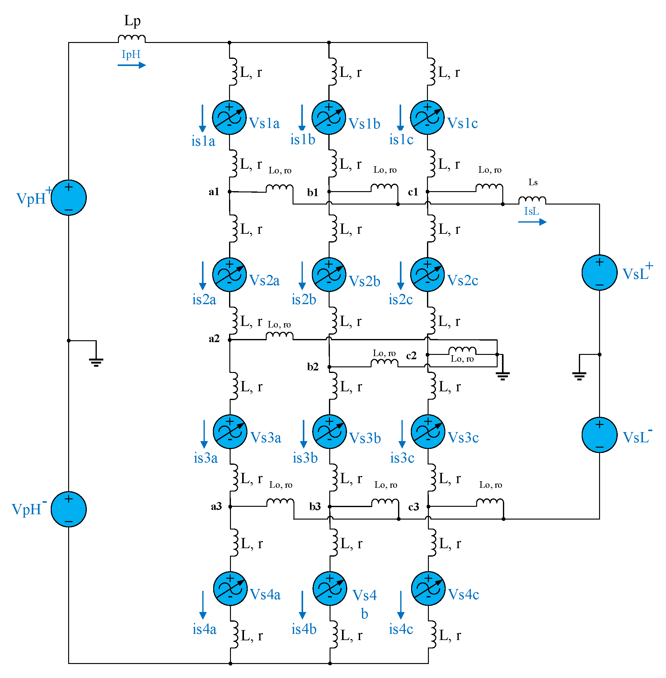
Proposed innovative non-isolated DC-DC MMC topology.
Figure 4.
Proposed innovative non-isolated DC-DC MMC topology.
Figure 5.
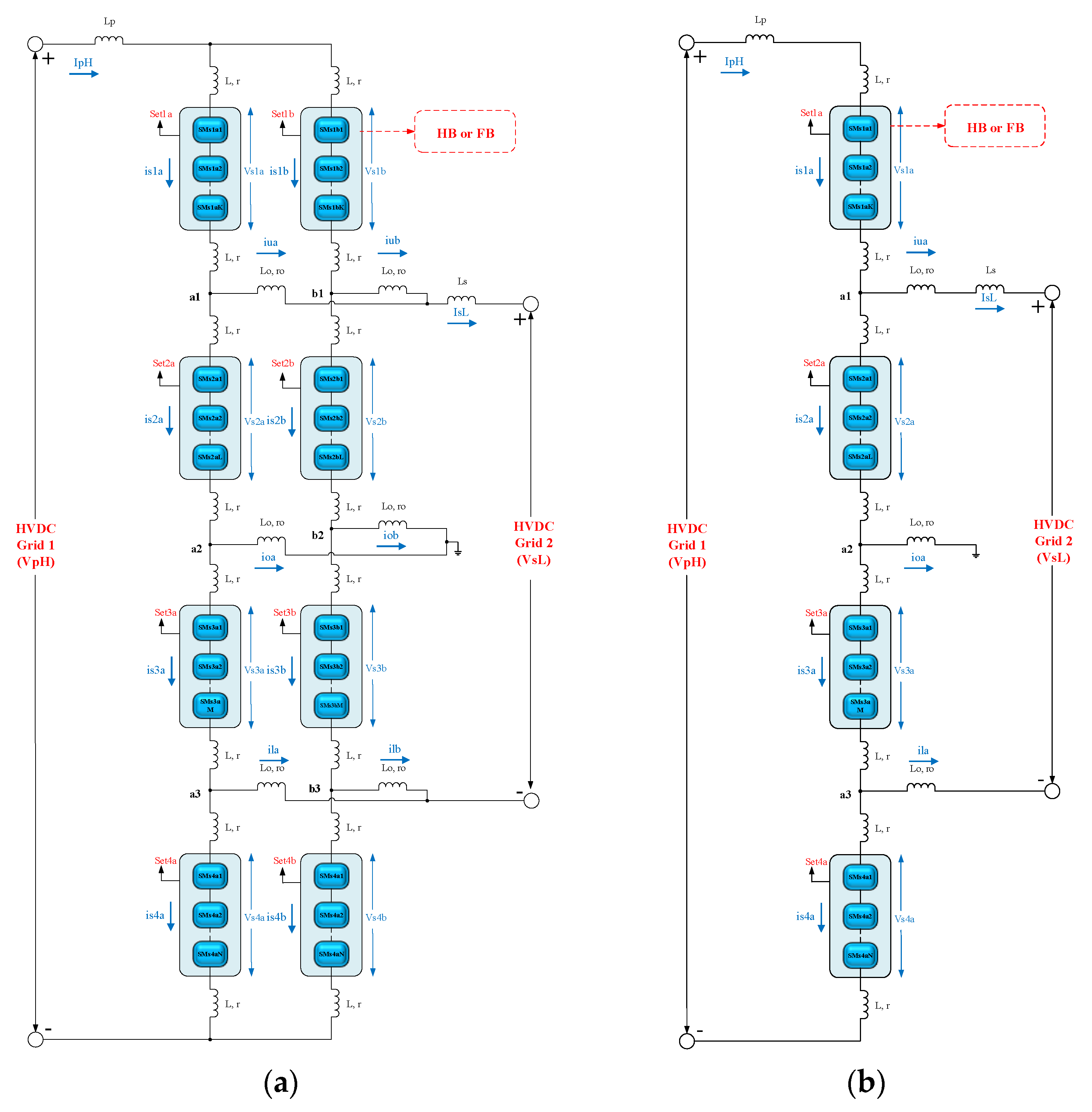
Proposed unique DC-DC MMC topology with 2-arm and 1-arm structures: (a) 2-arm structure; (b) 1-arm structure.
Figure 5.
Proposed unique DC-DC MMC topology with 2-arm and 1-arm structures: (a) 2-arm structure; (b) 1-arm structure.
Figure 6.
The recommended DC-DC MMC design's equivalent circuit.
Figure 6.
The recommended DC-DC MMC design's equivalent circuit.
Figure 7.
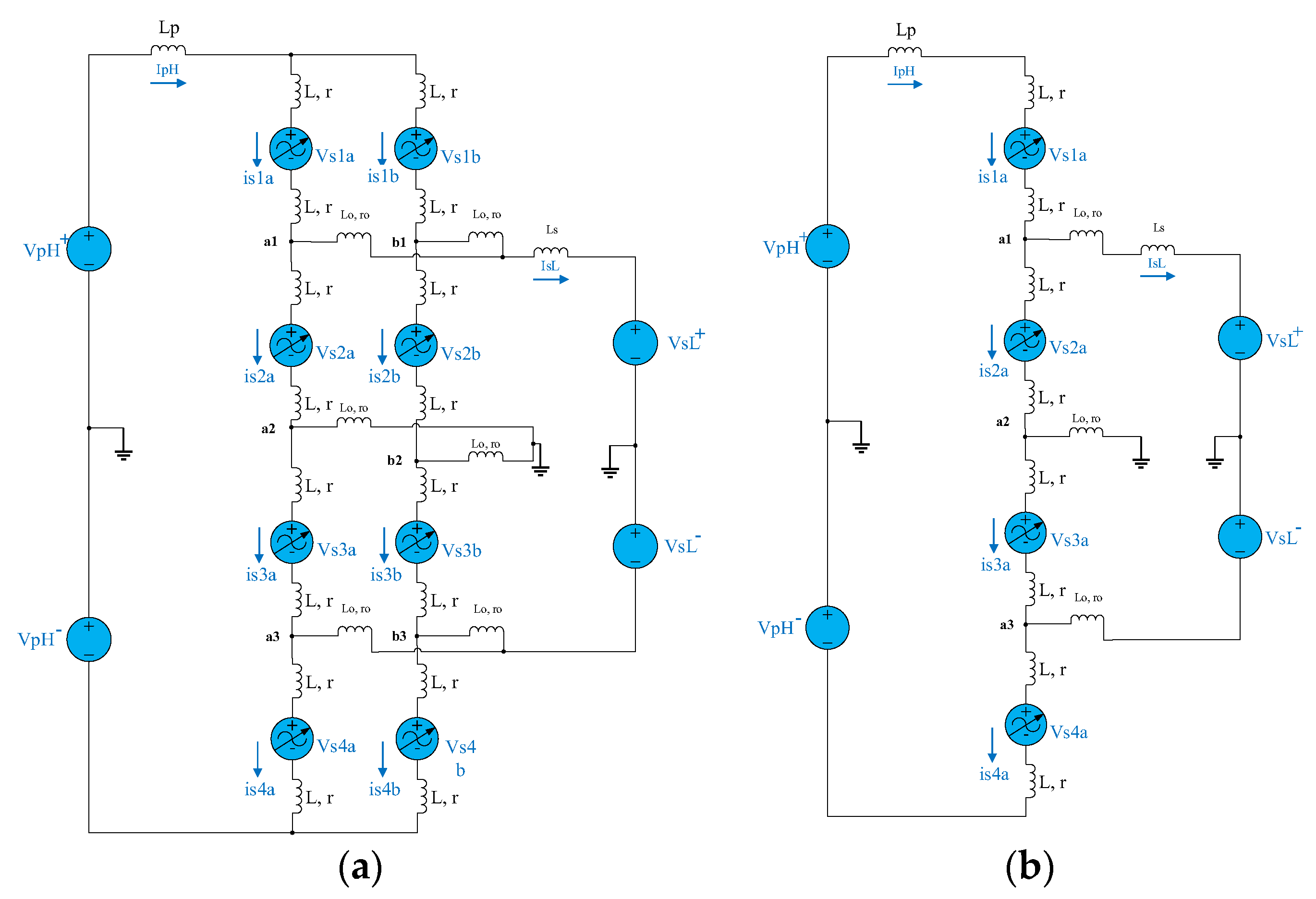
Proposed novel DC-DC MMC design's equivalent circuits with 2-arm and 1-arm structures: (a) 2-arm equivalent circuit structure; (b) 1-arm equivalent circuit structure.
Figure 7.
Proposed novel DC-DC MMC design's equivalent circuits with 2-arm and 1-arm structures: (a) 2-arm equivalent circuit structure; (b) 1-arm equivalent circuit structure.
Figure 8.
Interconnection of the two asynchronous HVAC power grids utilizing the proposed DC-DC MMC design.
Figure 8.
Interconnection of the two asynchronous HVAC power grids utilizing the proposed DC-DC MMC design.
Figure 9.
Overall the control and flow chart of the proposed DC-DC MMC design.
Figure 9.
Overall the control and flow chart of the proposed DC-DC MMC design.
Figure 10.
Voltage and current waveforms of the primary and secondary sides of the proposed DC-DC MMC topology.
Figure 10.
Voltage and current waveforms of the primary and secondary sides of the proposed DC-DC MMC topology.
Figure 11.
Power waveforms of the primary and secondary sides of the proposed DC-DC MMC topology: (a) full power waveforms; (b) magnified power waveforms.
Figure 11.
Power waveforms of the primary and secondary sides of the proposed DC-DC MMC topology: (a) full power waveforms; (b) magnified power waveforms.
Figure 12.
Voltages and currents of arm-a: (a) Set1a and Set2a waveform; (b) Set3a and Set4a waveform.
Figure 12.
Voltages and currents of arm-a: (a) Set1a and Set2a waveform; (b) Set3a and Set4a waveform.
Figure 13.
Set1a capacitor voltages of arm-a.
Figure 13.
Set1a capacitor voltages of arm-a.
Figure 14.
FFT analysis of primary and secondary waveforms: (a) Primary voltage FFT analysis; (b) Primary current FFT analysis; (c) Secondary voltage FFT analysis; (d) Secondary current FFT analysis.
Figure 14.
FFT analysis of primary and secondary waveforms: (a) Primary voltage FFT analysis; (b) Primary current FFT analysis; (c) Secondary voltage FFT analysis; (d) Secondary current FFT analysis.
Figure 15.
FFT analysis of arm-a voltages waveforms: (a) Set1a voltage FFT analysis; (b) Set2a voltage FFT analysis; (c) Set3a voltage FFT analysis; (d) Set4a voltage FFT analysis.
Figure 15.
FFT analysis of arm-a voltages waveforms: (a) Set1a voltage FFT analysis; (b) Set2a voltage FFT analysis; (c) Set3a voltage FFT analysis; (d) Set4a voltage FFT analysis.
Figure 16.
FFT analysis of arm-a currents waveforms: (a) Set1a current FFT analysis; (b) Set2a current FFT analysis; (c) Set3a current FFT analysis; (d) Set4a current FFT analysis.
Figure 16.
FFT analysis of arm-a currents waveforms: (a) Set1a current FFT analysis; (b) Set2a current FFT analysis; (c) Set3a current FFT analysis; (d) Set4a current FFT analysis.
Table 1.
Some DC-DC MMM topologies' contribution to the literature and application areas.
Table 1.
Some DC-DC MMM topologies' contribution to the literature and application areas.
| DC-DC MMC Study |
Application Area |
Contribution to Literature |
| [14] |
Hybrid HVDC grid interconnections |
The suggested concept can connect HVDC networks utilizing VSC and LCC and operate in four quadrants. |
| [21] |
HVDC grids |
A control strategy dependent on energy has been developed to fully regulate the energy and current elements during regular and abnormal operations. |
| [41] |
HVDC grids |
The suggested arrangement which is using the fewest possible semiconductors can effectively deliver high DC voltage multiplication through a DC failure- avoiding ability and sustained bi-directional power transmission. |
| [40] |
HVDC grid interconnections |
The suggested design has several benefits, including a reduced volume, more appealing investment costs, and reduced submodules. |
| [42] |
Rapid charging of electric vehicles |
The suggested design reduces the control complexities and switching number by using just a single half bridge-MMC arm. It is capable of preventing DC faults by nature and through galvanic isolation, a high voltage conversion rate can be obtained. |
| [43] |
Low-voltage direct current (LVDC) and medium-voltage direct current (MVDC) grid interconnections |
Decreased computational stress for power enforcement, circulating current mitigation, DC fault ride-through functioning, and transformer current optimization for improved effectiveness throughout the whole load range have been made possible by the suggested design. |
| [44] |
MVDC and HVDC grid interconnections. |
This paper suggests using the magnetizing inductance as a basis for an analytic analysis of the DC-DC MMC's performance. The difference method circulating current, converter powers, currents, capacitor voltage ripples, and soft-switching behavior are all shown to be significantly impacted by the magnetizing inductance. |
Table 2.
Parameters of the Simulated novel DC/DC MMC design.
Table 2.
Parameters of the Simulated novel DC/DC MMC design.
| Parameters |
Symbols |
Values |
| HVDC Grid 1 |
VpH |
262kV |
| HVDC Grid 2 |
VsL |
184kV |
| Arm Filtering Inductor |
Lo, ro1
|
20mH |
| Arm Inductor |
L, r1
|
3mH |
| Number of HBSM per Sets |
N |
4 |
| Number of Sets per Arm |
M |
4 |
| HBSM Capacitor |
VsC |
10mF |
| Switching Frequency |
fswc |
1000Hz |
| Number of Arms, K |
Arm-a, Arm-b Arm-c |
3 |

