Preprint
Article

Innate Orientating Behavior of a Multi-legged Robot Driven by the Neural Circuits of C. elegans

Altmetrics

Downloads

161

Views

78

Comments

0

A peer-reviewed article of this preprint also exists.

Submitted:

02 April 2024

Posted:

03 April 2024

You are already at the latest version

Alerts
Abstract
Biological neural network (BNN) is the core brain for creature to accomplish its intelligent behaviors through unique network structure and mechanisms. It also inspires controlling human-designed autonomous agents including robots to generate more advanced intelligent behaviors by mimicking the neural control mechanism of creatures at a deeper and more interactive level. Here, we constructed a whole-brain neural network model of Caenorhabditis elegans (C. elegans), which characterizes the electrochemical processes at the level of cellular synapse. The neural network simulation integrates computational programming and visualization of neurons and synapse connections of C. elegans, containing the specific controllable circuits summarization with their dynamic characteristics within the whole network. To illustrate its particular intelligent control capability in terms of robotics, we introduce the first innovative methodology for applying the BNN model to a 12-legged robot’s movement control based on the established numerical simulation platforms. We accomplished and designed two methods and corresponding encoding processes, one involving orientation control and the other involving locomotion generation, to demonstrate the intelligent control performance of BNN. Both simulation and experiment results indicate that the robot exhibits stronger autonomy and more intelligent moving performance under the control of BNN. We then summarized the contributions for digitalizing the C. elegans’ whole-brain neural network in real-time and utilizing it to control robot in a closed loop to validate its advanced intelligence control ability in terms of a scientific robot.
Keywords: 
Subject: Biology and Life Sciences  -   Neuroscience and Neurology

Author Summary

Biologically neural computing has always played a significant role in artificial intelligence with its specific network structure and integrative control principles, with increasing emphasis on the emulation of biological neural networks (BNN) recently. Motivated by advancements in neuroscience facilitating the digitization of the whole brain, we aim to focus on simulating the biologically autonomous control through modelling the whole brain network of C. elegans and applying it to robot control for demonstration and visualization. Starting from the bio-mimicking model and simulation of C. elegans, the BNN’s electrical dynamics are quantified in our calculation model, which is later used for the control platform of the robot. This study provides a systematic method for the motion control of a multi-legged robot utilizing the whole-brain biological neural network, which is validated on both numerical and experimental platforms with the generated positive results.
This method is established on:
  • Two integrated dynamic models of the C. elegans’ whole-brain network and the robot moving dynamics are built;
  • Real-time communication is achieved between the BNN model and the robot’s dynamical model including applicable encoding and decoding algorithms, facilitating their collaborative operation;
  • The cooperative work between the BNN model and the robot experimental prototype is also realized;
  • The study accomplishes the effective designed mechanisms of using BNN model to control the robot in our numerical and experimental tests, including the ‘foraging’ behavior control and locomotion control.

1. Introduction

In recent years, researchers increasingly focused on the study of digitizing a living brain [1,2,3] due to the new progress of the original biological neural network for investigating the biological intelligence including its dynamic properties [4] and control principles behind its specific behaviors [5]. Since the BNN possesses complex and efficient dynamical properties when realizing biological intelligence, it is valuable to study its intrinsic network structure and dynamical mechanism with robotics control application to learn from biological intelligence in this research, which allows the robot to generate more intelligent behaviors by mimicking the functioning of a biological neural network. According to the experiment data that most part of the whole-brain neural network system of C. elegans including micro-level and control function has been exploited [6], we chose to build a systematic model of its biological neuron network by programming. We completed a whole-brain dynamical neural computing simulations and visualize the whole-brain network with the color projection imaging corresponding to its electrical responses to validate the entire model and controllable circuits.
Aiming at the robot control enabled by BNN, there has been lots of research about brain-inspired intelligence control and its application recently. The research conducted by Mathias et al. [7] utilized a liquid neuron network inspired by the neural structure of C. elegans. This network consisted of only 19 neurons and was used to enable autonomous driving in both cars and drones. This technology is primarily used for controlling the part of the whole car driving system but is limited to relatively simple driving scenarios. In the OpenWorm project [8], some researchers put the whole-brain model of the biological neuron network of C. elegans in a Lego robot [9]. Their work is controlling the robot to have the ability of obstacle avoidance which is turning when colliding with the wall. However, it does not realize more complex behaviors while the performance of obstacle avoidance is not excellent enough. Meanwhile, Thomas et al. [10] developed a worm-like motion robot that utilizes the biological neural network of C. elegans to control, too. This robot is able to exhibit similar behaviors to C. elegans, but it has certain limitations in terms of its appearance and physical structure. Similarly, Deng et al. simulated a part of the biological neural circuit of C. elegans and built a simulation environment for a worm-like robot mechanism [11], while this approach neglected the whole-brain model simulation and lacks real experiments. Therefore, these studies develop a feasible methodology for replicating the complex behaviors and neural networks of C. elegans in robot systems but highlight the challenges and limitations faced in systematic verification and experiments. Consequently, we decided to tackle with those through completing a whole-brain model and implementing appropriate and persuasive control methods for both simulation and experiments.
We present a systematic method here to make BNN system and robot kinetic system interact with each other to control the robot moving with intelligent behaviors and performance instead of mimicking a whole worm. The intelligent behaviors of C. elegans like foraging and obstacle avoidance are consistent with the requirements for controlling a field robot [12], so the robot control based on similar intelligent behaviors can be inspired by the BNN with its unique characteristics when controlling C. elegans. The foraging and locomotion behaviors of C. elegans are exclusively controlled by corresponding specific circuits in the network referred to the existing biological experiments [13,14,15,16,17] (Locomotion control circuit in [13,15,17], mechanosensory circuits in [14] and navigation circuit in [16]) And we discovered and verified all the controllable circuits by analyzing the model simulation outputs. For the robot, the designed 12-legged radial skeleton robot possesses the function of walking on complex terrain [18] with its kinetic model developed completely. To establish the network as the control part of the robot, we designed practical control mechanisms and methods to apply the BNN control module to the robot moving in different steps, which also includes encoding and decoding of variables between BNN system and the robot kinetic system. These two systems can communicate with each other in real-time to control the robot through inter-process communication [19] while using two independent programming environments. The results show that BNN control could enable the robot to move in an autonomous and intelligent way with this efficient and unique control programming in both simulation and experiments.

2. Materials and Methods

2.1. Dynamic Simulation of C. elegans’ BNN

2.1.1. The Whole Brain Structure of C. elegans

The entire nervous system of the adult hermaphrodite C. elegans comprises 302 neurons and over 5000 synapses based on the original anatomy data [20,21] and summarization data [22]. Its intelligent behaviors of undulatory motion, turning, and obstacle avoidance are determined by its distributed neuron network and muscles. The biological neuron network of C. elegans can be categorized into three distinct layers that serve specific functions: sensory neurons, interneurons, and motor neurons. The role of sensory neurons is to convert a specific type of stimulus into action potentials through their receptors, known as sensory transduction. Typically, those stimuli originate from nature, like fluctuation of temperature [23] or changes in food concentration [24]. Additionally, sensory neurons in C. elegans are capable of mediating responses to physical stimuli, including the harsh touch of mechanical forces [25]. Research demonstrates that C. elegans possesses specialized mechanosensory neurons, including neurons called ASH [26,27], OLQ [27,28], CEP [29], and ADE [25,27], that sense specific mechanical stimuli. Furthermore, different sensory neurons manipulate various types of stimuli [25]. Upon activation, these neurons receive converted current input of a distinct type [25] which, in turn, generates action potentials via specific ion channels included in the neural network model. Secondly, interneurons enable communication between sensory and motor neurons, serving as central nodes for the transmission of electrical impulses in neural circuits. Thirdly, motor neurons stimulate muscle fibers by receiving impulses from presynaptic neurons, and finally, diverse motor neurons control various reactive movements of C. elegans through synapse connections with muscles. For instance, #DA [30] motor neurons control backward locomotion, and #DB [31] motor neurons regulate forward locomotion. Motor neurons RMD, RMB, SMB, and SMD [32] regulate the head-turning movements. The overall structure consists of three layers of neurons that form multiple functional circuits for controlling C. elegans and the whole neural network. For example, Figure 1 shows the circuit comprising the sensory neuron CEPVL, interneurons, and motor neurons, along with their topological connections. The synapse connection relationship between neurons and the related data including polarity and weights are all extracted from the EleganSign project website [33].

2.1.2. Modelling the Neural Network of C. elegans

The whole BNN model for C. elegans involves constructing individual neurons and their synaptic connections. Certain mathematical theorems establish the dynamic properties derived from both components. The model follows the Hodgkin-Huxley (HH) rule [34] for the individual neuron, which describes the relationship between its membrane potential and current, in line with the fundamentals of neuroscience. The set of nonlinear differential equations indicates that the current or voltage response can be numerically simulated through programming.
I = C m d V m d t + g ¯ K n 4 V m V K + g ¯ N a m 3 h V m V N a + g ¯ l ( V m V l ) d n d t = α n V m 1 n β n V m n d m d t = α m V m 1 m β m V m m d h d t = α h V m 1 h β h V m h
where I refers to the current that is applied to the neurons, V m represents the membrane potential, and C m denotes the electrical conductance of the neuron membrane. It has a constant value for all 302 neurons in this model. Furthermore, g ¯ K , g ¯ N a , and g ¯ l are the electrical conductance of potassium, sodium, and leak channels, respectively. Additionally, g ¯ l has a constant value for all neurons while g ¯ K and g ¯ N a hold different values for different neurons. The reversal potentials of three types of ion channels, namely V K , V N a , and V l , each have specified values for every neuron. The relevant constant parameters have been summarized in Table 1.
The second term I k = g ¯ K n 4 V m V K on the right-hand side of the formula represents the current of potassium ions, while the third term I N a = g ¯ N a m 3 h V m V N a refers to the current of sodium ions. The fourth term I l = g ¯ l ( V m V l ) corresponds to the leakage current. Accordingly, the conduction of current in a single neuron is facilitated by various ion channels that are distributed throughout. In the neural network of C. elegans, the parameters in the detailed expression of m , n , h vary for different ion channels and are also contingent on their respective gene expressions. In the whole-brain model, certain crucial ion channels have been selected, and their corresponding characteristics have been explored through published experiments [35]. Furthermore, specific ion channels, which were previously thought to have non-negligible effects on membrane voltage alterations, have also been included in this model. The latter formula demonstrates an equation for the calcium channel, which has distinct parameters and slightly different forms than the previous channels in the HH model.
I C A = g ¯ C A m C A 2 h C A ( V V C A )
where m and h have similar formulas with the other ion channels but different values for parameters in the expression of α and β .
It is of significance to note that some main potassium and calcium channels [25] are especially conducted by specific genes associated with mechanical force stimulus sensing, such as TRP-4 [36]. All the researched genes related to locomotion sensing are summarized in Table S1 in the Supporting Information. Meanwhile, this study postulates a linear relation between the gene expression and conductance values for each type of ion channel manipulated by distinct genes in all neurons, while the gene expression data for every neuron is extracted from the WormBase [37]. As a result, the conductance values for each neuron’s various ion channels can be determined by aggregating the necessary genes’ expression and relevant data across all neurons.
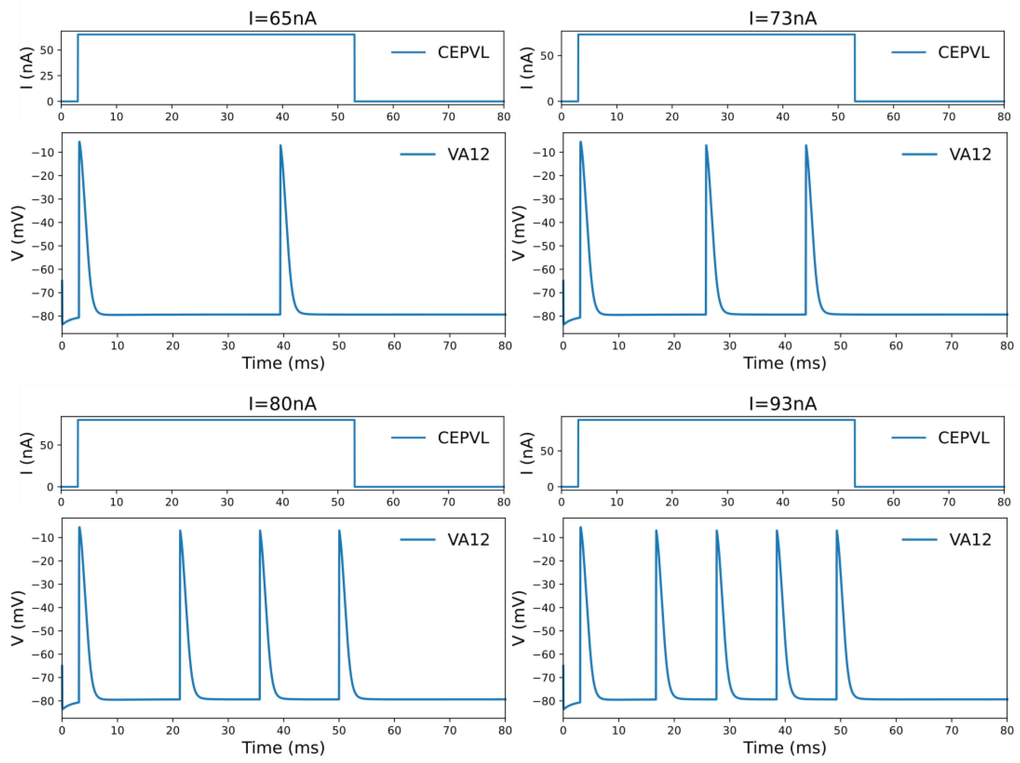
The simulation of an individual neuron is based on numerical computation of its action potential, which is generated by the current flowing across multiple ion channels distributed along the neurons as per the HH model. In addition, the simulation determines the dynamic characteristics of the membrane potential response of neurons. A significant finding in this context concerns the phenomenon observed in the HH model applied to C. elegans. Here, the voltage potential response displays oscillation behavior when the leakage conductance falls below a critical value of 0.299406 [38], attributed to the bifurcation of the HH model. This characteristic manifests as such: if the stimulating current applied to the neuron is low enough, it fails to elicit an action potential. Once the stimulation current reaches a critical level, the neuron will return to generating only one action potential. As the current surpasses a threshold, the neuron will fire multiple action potentials in a continuous and periodic pattern (see Figure 2). However, it will revert to generating a solitary action potential when the current is continuously increasing beyond a certain critical point.
Besides the model of single neurons, the neural network is formed by synapse connections between them. These synapses are classified as either excitatory or inhibitory, depending on the impact from the presynaptic to the postsynaptic neuron. The mathematical formulae that illustrate the synapse connection for this model are presented below.
I = g * v e g ' = g τ g = g + w
In this study, a simplified version of the synapse dynamic equation is utilized in comparison to the original model [34]. The purpose of this simplification is to decrease computational complexity while maintaining the analogous expression of the conductance parameter g . Specifically, for excitatory synapse, e = 0 and for inhibitory synapse, e = 80 . A membrane voltage threshold of -30 mV is set for chemical transmission of synapses. The postsynaptic neuron receives a current only when the voltage of the presynaptic neuron exceeds the threshold. We can construct a thorough computational model of the complete brain for simulation and analysis once we have the C. elegans synapse connection data, which includes polarity and weight extracted from the former presented website. We neglect gap junctions [39] from this model since they have been observed to exist in almost every neuron of C. elegans [40]. Running the simulation program with gap junctions is a considerable process, while research indicates it has little impact on the membrane potential v [41]. Overall, neurons on three synaptic-linked levels contribute to the neural network. Building the entire neural system is followed by using the program as a control element for the applied robot. The whole-brain model simulation codes are provided in File S1 in the Supporting Information. Notably, the NEURON tool with Python is the adopted simulation model tool in this study [42].

2.1.3. Control Circuit Identification

Underlying the complete network structure of C. elegans are specific neural circuits that regulate its movement and behavior [43], which include forward and reverse locomotion[44], as well as direction-switching [17]. These circuits are primarily made up of sensory neurons that are functionally specialized in controlling motor neurons. To develop intelligent robot behaviors based on the mechanisms of C. elegans, it is essential to locate the controllable circuits in its neural network. For instance, previous studies indicate that ASH sensory neurons, as well as AVA, AVD interneurons, and DA motor neurons, can regulate reverse locomotion [17]. Additionally, the OLQ sensory neurons and RMD motor neurons can govern head withdrawal [45].
Through simulation, the identification of specific circuits can be ascertained by contrasting the voltage responses of all motor neurons. This differentiation manifests in the form of distinct voltage responses among specific motor neurons when subjected to current input alterations of their corresponding sensory neurons, while others exhibit no such dependency. By stimulating an individual sensory neuron with an input current of a large value range, the voltage response across all the motor neurons will be output through simulation to do subsequent analysis and summary. As a result, by continuously activating different sensory neurons, additional circuits are discovered within the whole-brain network model simulation, each with its specific sensory and motor neurons.
This study proceeded to investigate the circuits’ dynamic properties by examining the voltage response features of relevant motor neurons through whole-brain model simulation. Some motor neurons exhibited voltage response oscillations, while others did not generate oscillation after activation. (The simulation results are presented in Figure 2.) Virtually, this phenomenon can be referred to determine the motor neuron decoding approaches, such as continuous spiking frequency decoding or digital binary decoding for decision-making. Additionally, the motor neurons’ potential response oscillation generation relies on the connected sensory neuron and the specific control circuit. For example, DA motor neurons generate voltage oscillation when activated by the sensory neuron ADEL, but one single action potential only when activated by the sensory neuron ASHL. Therefore, the dynamic responding features of motor neurons have to be derived from certain connected circuits in the controlling part of the whole-brain model.
All the observed and researched useful circuits with their corresponding sensory neurons and motor neurons are shown in Table 2. Among them, all the sensory neurons are mechanosensory neurons. The range of voltage response oscillation for the current stimulus is summarized for use in the control section. The obtained circuits have been confirmed and testified by prior research and experiments, indicating the presence and functional control of the circuits beneath the C. elegans. These findings will be utilized in the control model for the subsequent decoding and encoding module.

2.2. Robotic platforms

2.2.1. 12-legged Radial-Skeleton Robot

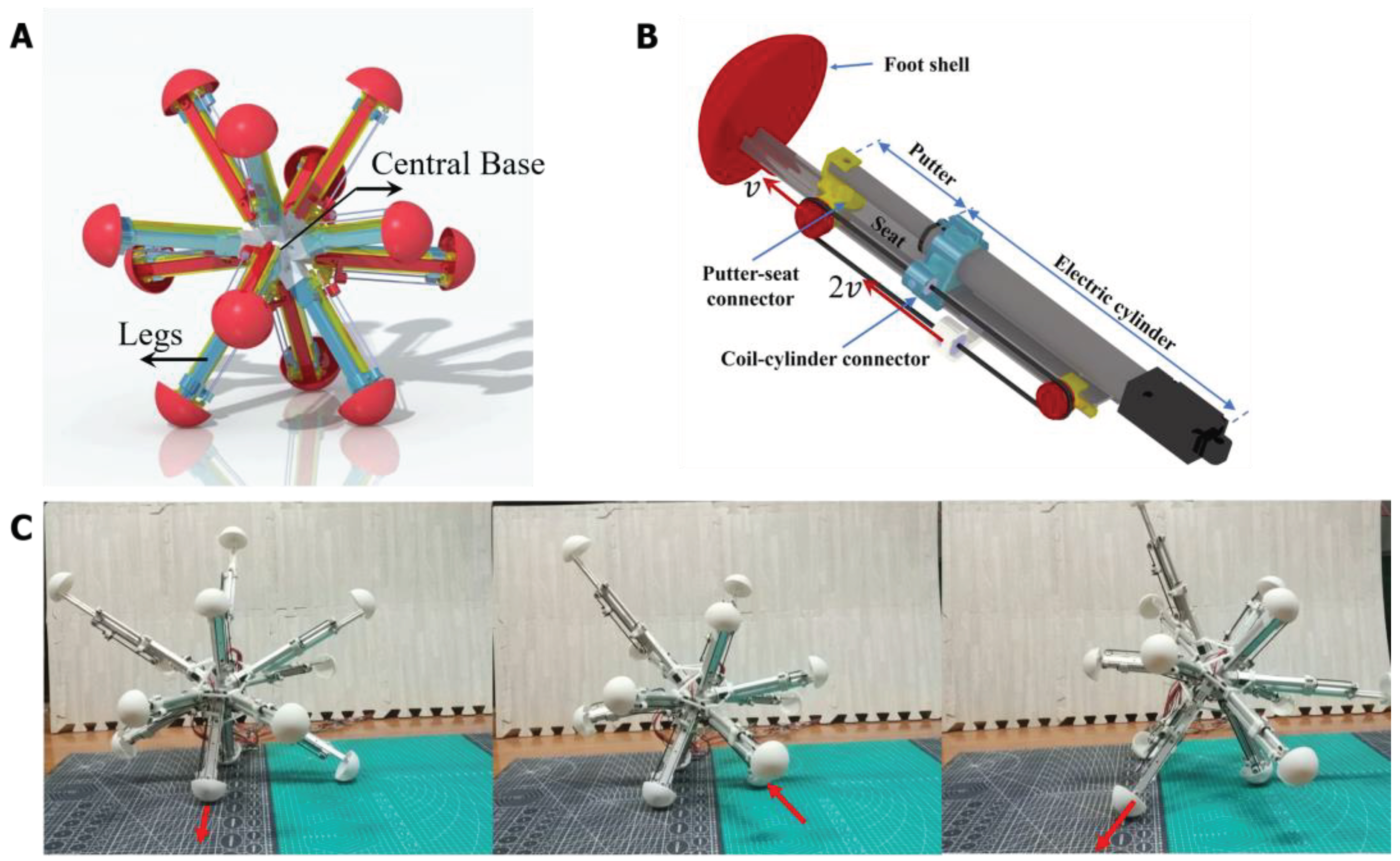
A designed 12-legged radial skeleton robot is employed as the controlled object of the BNN model. It is a previously developed robot, which has a fully functional dynamical model [46,47,48]. The robot realized the main functions of creeping, walking, obstacle avoiding, etc., which are equally simple as C. elegans, so it is determined as applying object for the whole-brain BNN model. The radial-legged robot is composed of the robot base and legs fixed on one end of the base (Shown in Figure 3A) and its main application scenario is about complex terrain detection because of its unique appearance feature. The base of the robot is designed to be a spherical shell with 12 sleeves distributed uniformly on the surface for connecting legs. At the same time, the amount of legs is decided to be 12 by computing and testing, so that it has the best capacity for walking on rough terrain [49]. More importantly, the legs of the robot can stretch out and draw back relying on the two-way pulley mechanism shown in Figure 3B.
As shown in Figure 3B, taking the first section as the study object, the pulley fixed on the first section extends with the second section at a speed of V. A point on one side of the coil is fixed on the robot base and moves to the right at a relative speed of V to the first section, while the coil on the other side moves to the left at a relative speed to the first section. Adding the convected velocity of the first section, the second section finally elongates at the speed of 2V. In total, the robot reaches a radial expansion ratio of 2.08 which makes it have better rolling ability [49]. Meanwhile, the foot shell is installed on the bottom end of the slide rail, which adopts the hemispherical design that the foot can contact with the ground omnidirectionally. It is relatively rough so that the sliding of the foot can be decreased in the real experiment. In total, the moving process of the radial skeleton robot is that the center of gravity moves with the support triangle composed of three grounding legs with their length expanding. Then the robot will roll in one direction. (Shown in Figure 3C)

2.2.2. Kinetic Model of Robot for Simulation

Corresponding to the robot’s motion pattern, we build its kinetic model [18]. Since the main mass of the robot is concentrated on the central base and the motors with their electric cylinders are firmly connected to the base, the change of mass distribution of the robot is not significant in the moving process. As a result, in this paper, the robot is simplified as a solid ball with uniformly distributed mass when calculating the moment of inertia. We take the robot as a multi-rigid-body system in this dynamic model and we consider the changing length of legs as the time-varying constraints. Consequently, state variables of the central rigid body can describe the whole robot movement. They are:
q = [ x ,   y ,   z ,   λ 0 ,   λ 1 ,   λ 2 ,   λ 3 ,   v x ,   v y ,   v z ,   ω x ,   ω y ,   ω z ] T
In the formula, x ,   y , and z denote the coordinate of center of mass of the robot under the Cartesian coordinate system which is also the inertial reference system. λ 0 ,   λ 1 ,   λ 2 ,   λ 3 represent the robot attitude as quaternion. v x ,   v y ,   v z represent the velocity of the center of mass under an inertial reference system. ω x ,   ω y ,   ω z represent the angular velocity of the robot under the accessory coordinate system.
Neglecting the mass of stretching legs, the acceleration of the center of mass in simulation environment can be given by the motion theorem of center of mass:
[ x ˙ , y ˙ , z ˙ , v ˙ x , v ˙ y , v ˙ z ] T = [ v x , v y , v z , F x m , F y m , F z m ] T
where m means the mass of robot, F x , F y , F z are the external forces of the robot, including gravity and contact forces.
Usually, we use Euler angles to describe the attitude of the object. However, the spherical multi-legged robot can change its motion attitude in a large range when doing rolling movement which means it is easy for the robot to be in the singular configuration. As a result, in the dynamic model, we adopted a quaternion algorithm to represent the attitude of the robot. The derivative of the quaternion is based on the following formula:
[ λ ˙ 0 , λ ˙ 1 , λ ˙ 2 , λ ˙ 3 ] T = 1 2 λ 1 λ 2 λ 3 λ 0 λ 3 λ 2 λ 3 λ 0 λ 1 λ 2 λ 1 λ 0 ω x ω y ω z
And the angular accelerations of accessory coordinate system of the robot can be calculated by the Newton-Euler Dynamic Equation.
J x ω ˙ x + J z J y ω y ω z = M x J y ω ˙ y + J x J z ω x ω z = M y J z ω ˙ z + J y J x ω y ω x = M z
where J x , J y , J z are the moment of inertia of the robot and M x , M y , M z are the momentum acting on the robot with their projection components on the inertial principle body axis coordinate system. To simplify the calculation, take the robot as a sphere having its mass distributed uniformly. Therefore, the moment inertia of the random axis that passes through the center of mass is equal. Then the formula will become:
ω ˙ x , ω ˙ y , ω ˙ z = M x J x , M y J y , M z J z
After determining the robot’s kinematics, its entire kinetic simulation is created through computer programming. This demonstrates the robot’s motion for a few simple movements in the initial phase. Additionally, interfaces are established between the robot simulation and biological neural network models, which involve encoding and decoding codes, and real-time SOCKET communication [50] between two programming systems.

2.2.3. Construction of the Experiment Platform

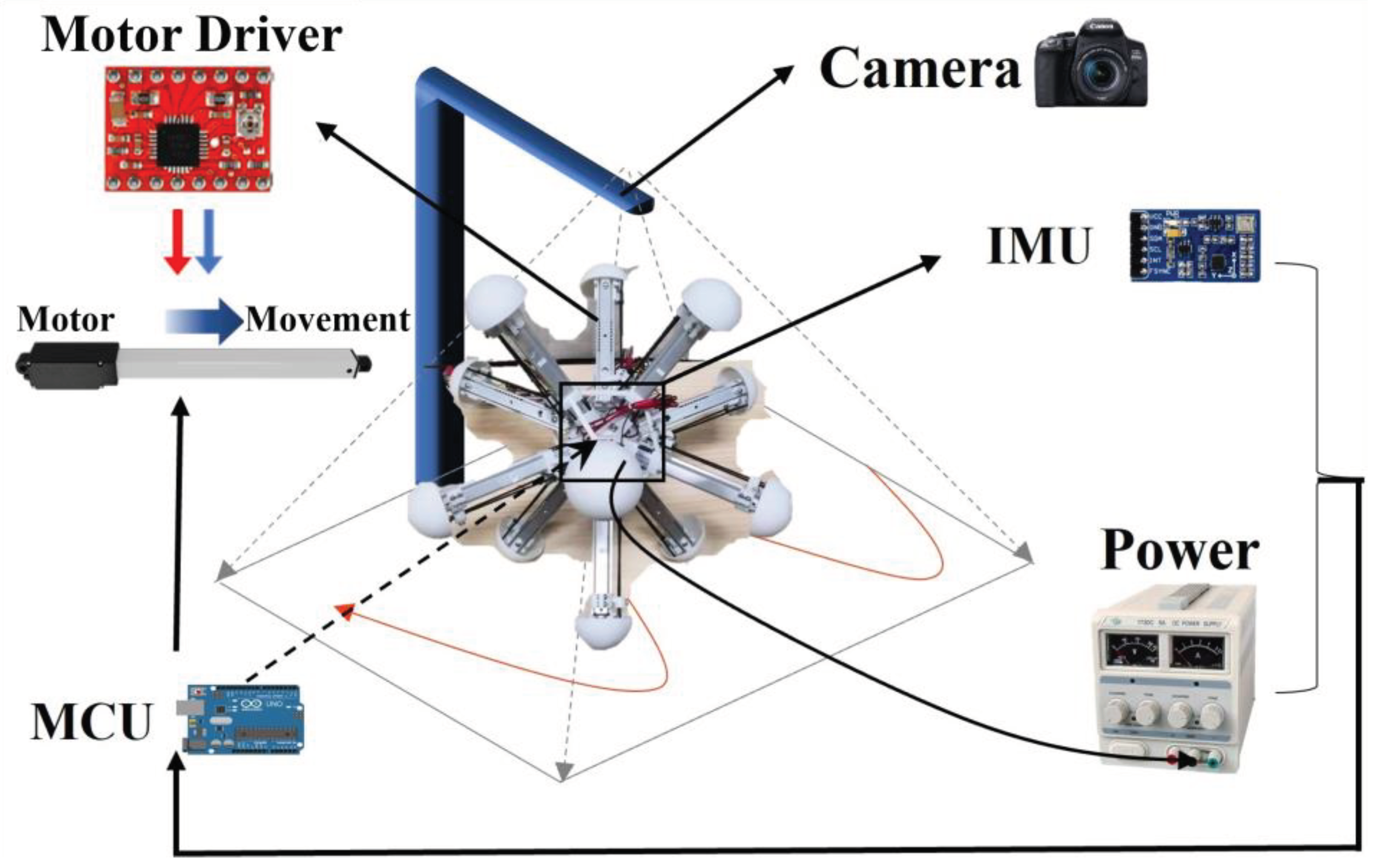
The robot is manufactured and assembled according to its mechanical design, and equipped with essential sensors and necessary hardware based on experiment preparation. The necessary motors are also installed to control the legs, which are fixed at one end to the central base. To achieve closed-loop control, the robot control system is divided into three parts: perception, decision, and motor execution. The IMU (Inertial Measurement Unit) measures the angle, angular velocity, and acceleration in real-time and transmits the data to the microcontroller via serial port communication. The Arduino microcontroller, responsible for the calculation function, converts the sensor’s original input information into the robot’s posture and determines the speed and direction of each leg’s movement. These two parts determined the robot’s competence in proprioception and basic control for the latter experiments with BNN control. The robot uses the power supply to power the MCU (Microcontroller Unit), the IMU, the motor controller, and the motors. The power supply and all the devices are installed in the central base, together with the necessary counterweight to ensure that the center of gravity is approximately the center of the base. In addition, the research has carried imperative hardware device modules to do the field experiments in terms of the whole platform, such as the camera distributed above the robot and different types of ground for the robot to move. Figure 4 shows the whole hardware and connection relationship. Meanwhile, the BNN model can communicate with the serial communication module of the robot central panel remotely in real-time. As a result, simulation and experimentation can all be realized in this research. To ensure a high degree of fidelity between the simulation results and the actual motion of the robot, the parameters of the robot within the simulation environment are all the same as those of the real robot (Table S2 in Supporting Information).

3. Results

3.1. Visualization of the Whole-Brain BNN Model

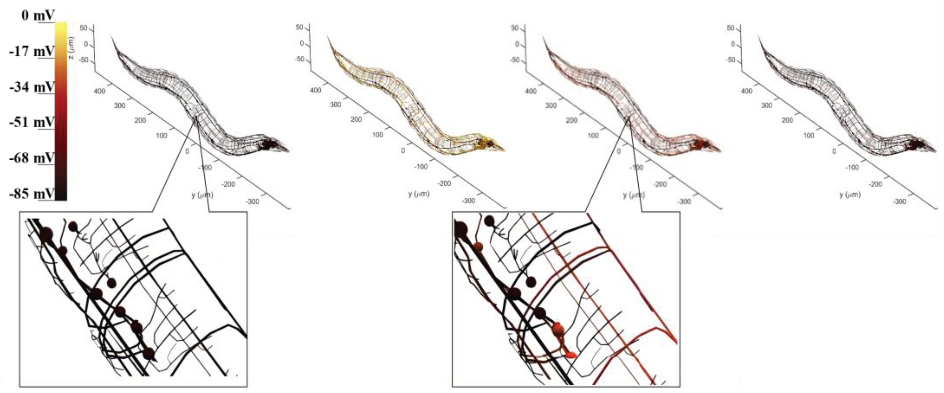
The visualization of the BNN is to objectively examine model simulation results based on a previously determined circuit under the whole-brain model, which contains neuron morphology and voltage response projection. The whole-brain neural network of C. elegans is plotted while incorporating the morphology data of each neuron to ensure accurate representation. During model simulation, the electrical membrane potential response of neurons can be recorded when stimulated by current inputs from sensory neurons. By tracking the state of these recorded neurons, a corresponding color change can demonstrate the dynamic transduction of electricity between neurons. This brings to light that many neurons are activated during the entire process through the current stimulation of sensory neurons. Figure 5 illustrates the control circuit with CEPVL, showcasing the electrical transduction visualization, where the voltage response of the neurons corresponds directly to color alterations. The activating process of neurons dictates that voltage changes from a static state to an activated state suddenly and returns to a static state relatively slowly, leading to a rapid color change from black to yellow, and back to red and black for neuron visualization. Consequently, the plot results exhibit and testify to the circuit’s dynamic characteristics along with the neural network model’s overall morphology and configuration. All the morphology data of the whole-brain neural network neurons are extracted from the NeuroMorpho.Org [51] and then plotted by MATLAB.

3.2. BNN Model Controls Robot Orientating

3.2.1. Mechanism for BNN to Control Robot

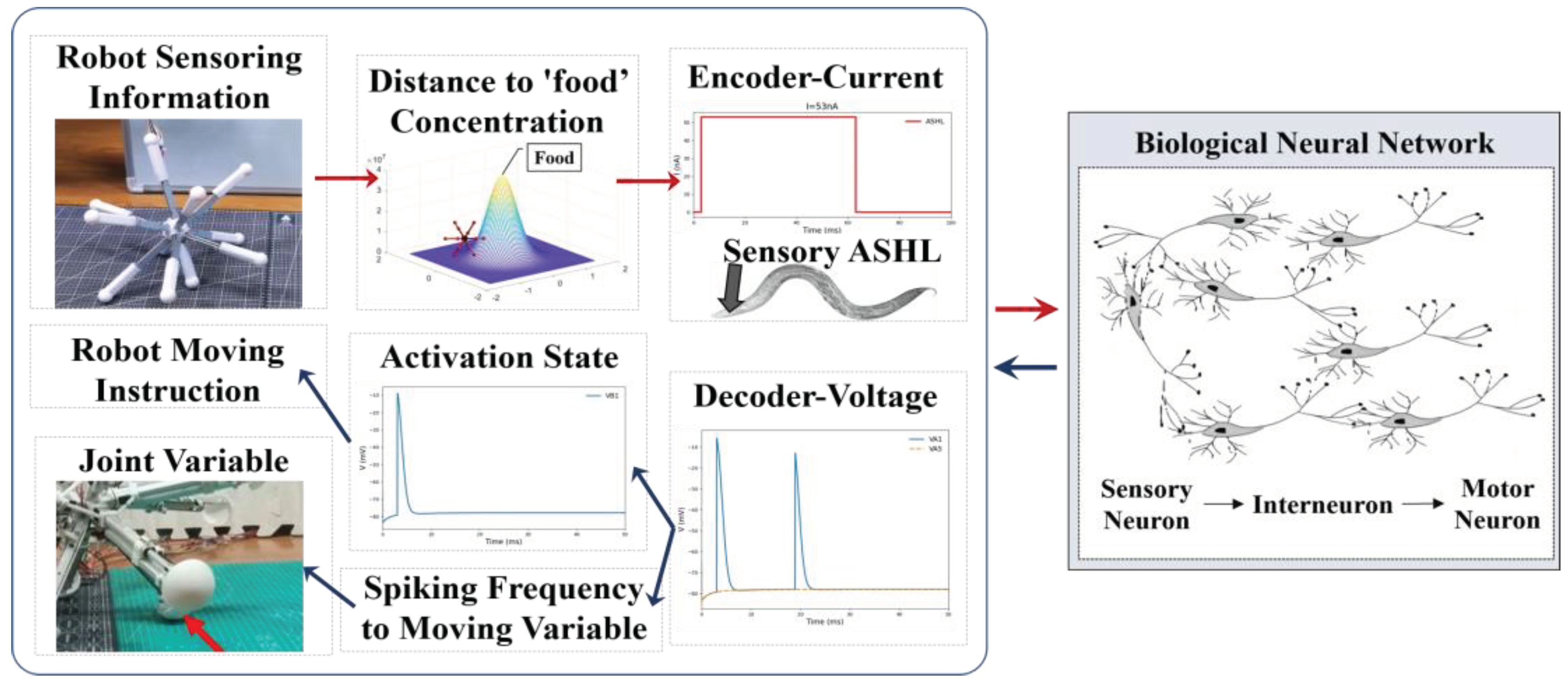
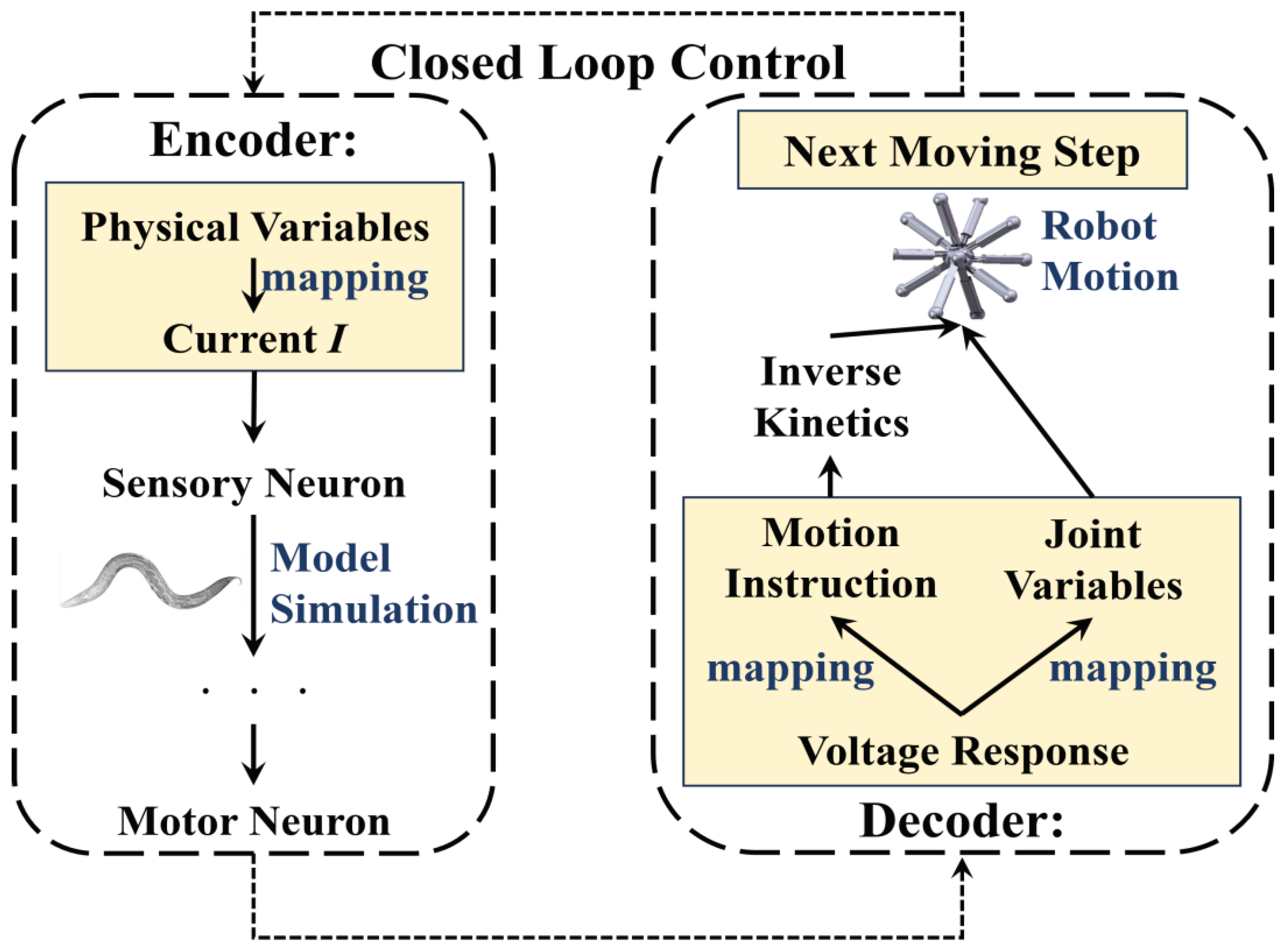
Starting from the whole concept of employing the BNN model for robot control, it is imperative to derive the basic control mechanism firstly through learning from the biological intelligent control system. In general, the mechanism for biological neural networks to control C. elegans’ behavior is relatively clear [52,53]: initially, sensory neurons detect environmental stimuli such as changes in food concentration and generate action potentials. From there, through signal transduction, the sensory neurons activate their postsynaptic neurons, which include interneurons and motor neurons in particular control circuits. The muscles will generate either shrinking or relaxing movements to facilitate the responsive motion of C. elegans, driven by electrical transduction from motor neurons. This transduction, which operates based on three layers of neurons and muscles, determines the BNN’s capacity to control the creature’s intelligent behaviors. Therefore, with reference to the BNN model mechanism, the robot’s control method can adopt this entire information processing of the biological neural network’s behavior and dynamic features. This approach includes transforming the biological environment stimulus signal into physical sensing signals for the robot and the micro-behavior of biological muscles into physical information for robot motion. On the one hand, by replacing the genuine biological stimuli experienced by sensory neurons, the robot sensors can encode input into stimulation current format based on the BNN model. On the other hand, the method employs the diverse dynamic features of motor neuron voltage responses to decode control of robot joint motion, substituting for actual biological muscles. This is because the lack of clarity in the mathematical relationship between motor neurons and muscles [54] limits decoding from the muscles directly. In this procedure, the data from the robot sensors will be transformed into current stimulation and used as input stimuli for the sensory neurons. The robot joints, controlled by the motor neuron simulation output, will act as the muscles of C. elegans. Figure 6 illustrates the conceptual framework of this comprehensive research method.
In terms of the current stimuli form, previous research suggests that certain mechanosensory neurons respond to particular current stimuli patterns [25]. However, based on simulation results using the network model, it is not appropriate to use this method in the current model. Instead, a constant value for current is input over a continuous time. (Shown in Figure 6) It has been determined that voltage response undergoes continuous change following simulation, providing insight into its dynamic properties. Therefore, according to the specific dynamic characteristics of motor neurons, the voltage response can be directly decoded into the leg length changing or motion instruction for the multi-legged robot. For the latter methods, the motion instruction can be transformed into the command of electrical motors in an experiment or the command of each leg’s length extension value based on inverse kinetics in simulation. The binary activation state of non-oscillatory motor neurons after activation can be deciphered into discrete variables for movement instructions. The former approach decodes the spiking frequency of motor neurons’ voltage response into continuous variables, including joint movement variables which correspond to the muscle’s relevant motion variables in C. elegans, based on their oscillation behaviors. The encoding and decoding processes are detailed in Figure 6.
In addition to implementing the fundamental combination approach of the BNN model and the robot system, our attention was also directed toward selecting appropriate sensory and motor neurons for the control loop in this study. For C. elegans, a range of composite control circuits, incorporating operational sensory and motor neurons, facilitate its intelligent behavior control, such as foraging and avoiding obstacles. Consequently, except for the basic motion control modulated from motor neurons, the specific targeted control circuits should be determined with their kinetic characteristics to be combined with intelligent control for robot, as well as the sensory neurons and motor neurons to be encoded and decoded. For instance, the sensory neuron ADEL/R are dopaminergic nose touch mechanoceptors. They modulate locomotion behavior in response to the presence of food by textural mechanosensation [55]. When acting a current stimulus on ADER sensory neurons ranging from 59nA to 68nA, bifurcation of voltage response will take place in the motor neurons containing DA, DB, VA, VB, and VD. (According to the Table S2 in supplementary materials) Setting the value of leakage conductance, the spiking frequency of voltage response oscillation of them can be decoded continuously to the length change of robot legs. (Similar to Figure 2) By choosing 12 neurons among them, the length changing of legs can be connected with voltage decoding of motor neurons. Once all the leg lengths are determined, the robot can move in a certain way. Consequently, it is feasible to use BNN model to control the basic motion of robot by determining the appropriate circuit. (The realization platform aiming at the whole mechanism including the interaction between the two simulation systems is also shown in Figure A1 in Supporting Information.) Furthermore, the particular intelligent conduct of a robot is predominantly achieved by developing field missions that pertain to brain-inspired intelligence, stemming from the basic mobility feature.

3.2.2. Innate ‘Foraging’ Behavior Control

Inspired by C. elegans, the control for the robot could learn from imitating the biological intelligence first to generate similar intelligent behaviors of the robot. For instance, C. elegans can squirm to the food slowly by detecting and following the increasing gradient of food concentration [56]. Combining this with basic robot functions, such as locomotion and rolling on the ground, could enable similar mission planning for the robot, allowing it to move toward a target point. In the natural habitat of C. elegans, alterations in food concentration rely solely on the distance between the worm and the food source [56]. Consequently, for practical control purposes, we can also convert the distance between the robot and its target point into a ‘food’ concentration to link the BNN control mechanism with the robot.
For C. elegans, when the food concentration changing signal is stimulated to sensory neurons, the whole neural network will transmit the corresponding signals to muscles distributed along the body directly to do the undulatory or turning motion [57] to respond to the food alteration environment. For instance, when food with increasing concentration is nearby, the whole neural network and muscle activities are triggered to move C. elegans closer to the food.
In correspondence with the neural behavior, the robot uses an indicative input signal to detect its proximity to the target point by mimicking C. elegans’ intelligent mechanism, which detects whether the robot moves along the direction of the increasing ‘food’ concentration. Therefore, considering the changes in the ‘food’ concentration, the input current will directly stimulate the sensory neurons. This, in turn, allows the BNN model to control the robot altering the distance to the target point. Meanwhile, the robot’s motion can be controlled by decoding joint moving variable values from the voltage response of specific motor neurons in the chosen circuit, or by following moving instructions generated by the BNN to produce intelligent motion. An appropriate decoding method is essential in this control mechanism, and we conducted preliminary experiments to test two decoding methods.
Building on the previous idea, we begin with using the circuit containing the oscillation phenomenon on motor neurons, which allows for continuous decoding of leg extension length. This was necessary because the output of the BNN needs to be decoded directly to the leg length changing of the robot in the former idea, and we selected 12 motor neurons to connect with the 12 legs in the chosen circuit ADER-VA which satisfies the requirements for this method. To align with the input current range of oscillation for sensory neurons such as ADER, it is necessary to limit the range of current stimulation to a small interval. Additionally, the value of input current is correlated with the distance between the robot and the target point. Therefore, during the robot’s movement, the control process should follow these steps: if the robot is further from the target in the previous step, the current stimulated by the sensory neuron will be relatively smaller in alignment with the encoding. Regarding the oscillation phenomenon, a low current will result in a longer period of action spike. The decoded output should assist the robot in moving closer to the target in the next step. If the robot moves closer to the target in the previous step, the current will increase, resulting in a higher frequency of action spikes. This change should also aid the robot in moving closer to the target in the next step.
In this procedure, to determine the mathematical correlation between the voltage response of the motor neurons and the leg extension length, a differential equation expression [11] was used. However, the initial findings have shown that the robot cannot perform well under this muscle-joint motion method[11], which directly connects the response of the 12 motor neurons with the 12 legs’ extension motion. It indicates that the robot exhibits smooth movement during the initial few seconds, but it fails to display intelligent movement thereafter which shows the ineffectual moving results controlled by direct spiking frequency encoding to joint variables of the robot. (The detailed video of the robot moving in simulation is also shown in Video S2 in Supporting Information which leads to a failed moving situation at the end.) This is particularly because the robot has a distinct kinematic model from that of C. elegans, restricting to apply the whole-brain model absolutely to the robot’s self-intelligence control without considering the robot’s specific moving properties. Therefore, the intelligent ‘foraging’ control for the robot cannot be achieved solely by employing the direct decoding method and the ADER circuit only.
For the latter control thought, since the robot has a distinctive moving mechanism with C. elegans, it is practicable to make the biological neural network do the policy deciding to aim at a specific intelligent function of the robot motion instead of being projected to the moving joint variables for the robot directly. For this method, the policy can be the moving direction for the robot in terms of the ‘foraging’ behavior. To employ the BNN as the direction control element for the robot system, integration of the robot’s kinetic model is compulsory for an all-inclusive closed loop. This ensures the robot’s motion is controlled. As per inverse kinetics, once the direction of motion for the robot is established, the variables for each joint can be resolved so that the robot can move along the predetermined direction to complete the whole ‘foraging’ behavior. It should be noted that the decision for the direction can either be the absolute direction indicating the ‘food,’ or the relative direction that is based upon exploring the environment.
In the first place, robots can construct an absolute coordinate system by employing computer sensors [58]. However, it is hard for the biological neural network model of C. elegans to decide the precise direction in three-dimensional space. This study has shown that neural circuits like CEPDL-VA, which can be decoded to a continuous direction angle variable, cannot perform the task of moving a robot to an arbitrary point utilizing the methods of absolute geometry. In the second place, drawing on the foraging behavior of C. elegans, the worm decides its locomotion direction step by step on the feedback of food concentration [56] even though it is not equipped with an advanced navigation system. In this process, it will follow the previous direction or move forward if the food concentration is increasing. But it will have a reversed motion when the food concentration in the previous step is decreasing [24]. Consequently, it can move towards the food gradient ascending direction simply without learning the environment completely although it may not be the shortest path.
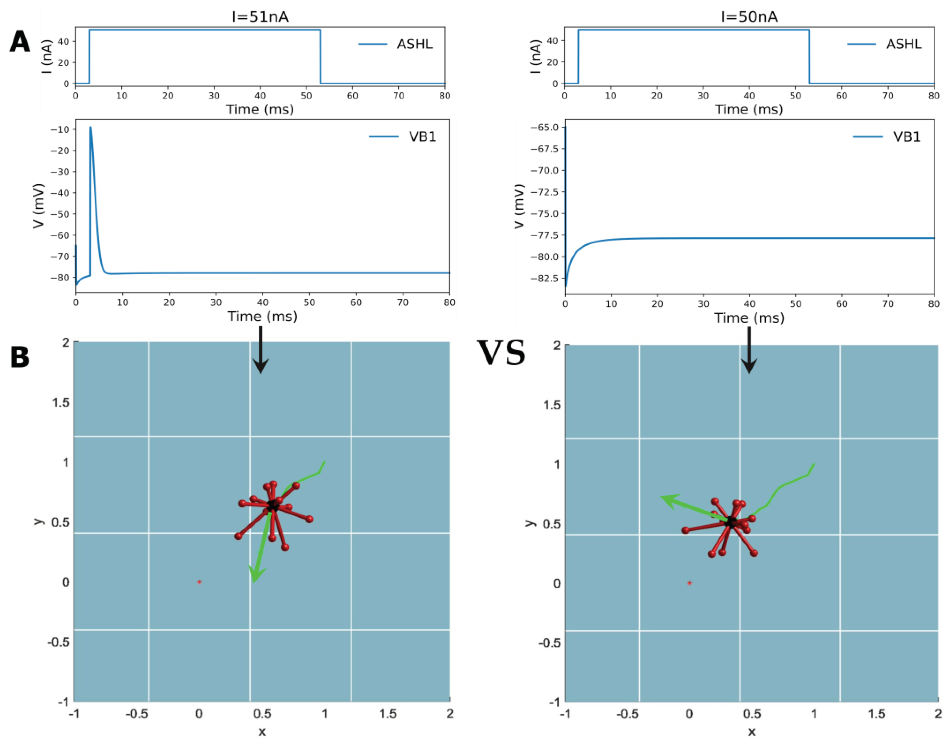
By emulating this behavior, the study designed a digital environment to simulate robot movement toward food concentration. The gradient’s value transformation is modeled on a Gaussian distribution, indicating a lower food concentration value when the robot is further from the target point. As a consequence, the study based on this imitating ‘foraging’ behavior concludes that if the food concentration is higher in the current step than in the previous one, the robot will continue to move in the previous direction. When the concentration of ‘food’ drops below that of the previous step, the robot selects a random direction for the next step until it detects an increase in concentration. Unlike C. elegans, the study utilizes random angle turns instead of predetermined angles due to the robot’s difficulty in controlling itself and turning at suitable points during the ‘food’ search process. In this process, the biological neural network carries out the function of decision-making. Thus, the designated circuit ASHL-VB1, which is decoded into a binary digital signal of either 0 or 1, is chosen (as evident in Table 2). The electrical dynamic aspects of this circuit indicate the absence of any oscillation phenomena with only one action potential or none, as shown in Figure 7A. ASHL represents the primary nociceptor, eliciting avoidance responses to noxious stimuli. The alteration in value for “concentration” is decoded directly into the current that is stimulating the sensory neuron ASHL. If the concentration rises, the current surpasses the threshold value needed for the corresponding motor neuron to activate. If the concentration declines, the current falls below this value. The mathematical expression of concentration changing is
f x = 10000000 * e 2 * x 2
where x represents the distance from the target point to the robot and f x means the ‘food’ concentration at that point. The reason why the expression has a very large coefficient is when the displacement of the robot between two steps is extremely small, the current input for the sensory neuron will still pass the threshold as long as the robot is moving closer to the target point. Meanwhile, f x is decoded directly to the stimulation current acting on the sensory neuron. I x i = 51 + f x i f ( x i 1 ) , where x i means the current state, x i 1 means the previous state and the value 51 is according to the current threshold.
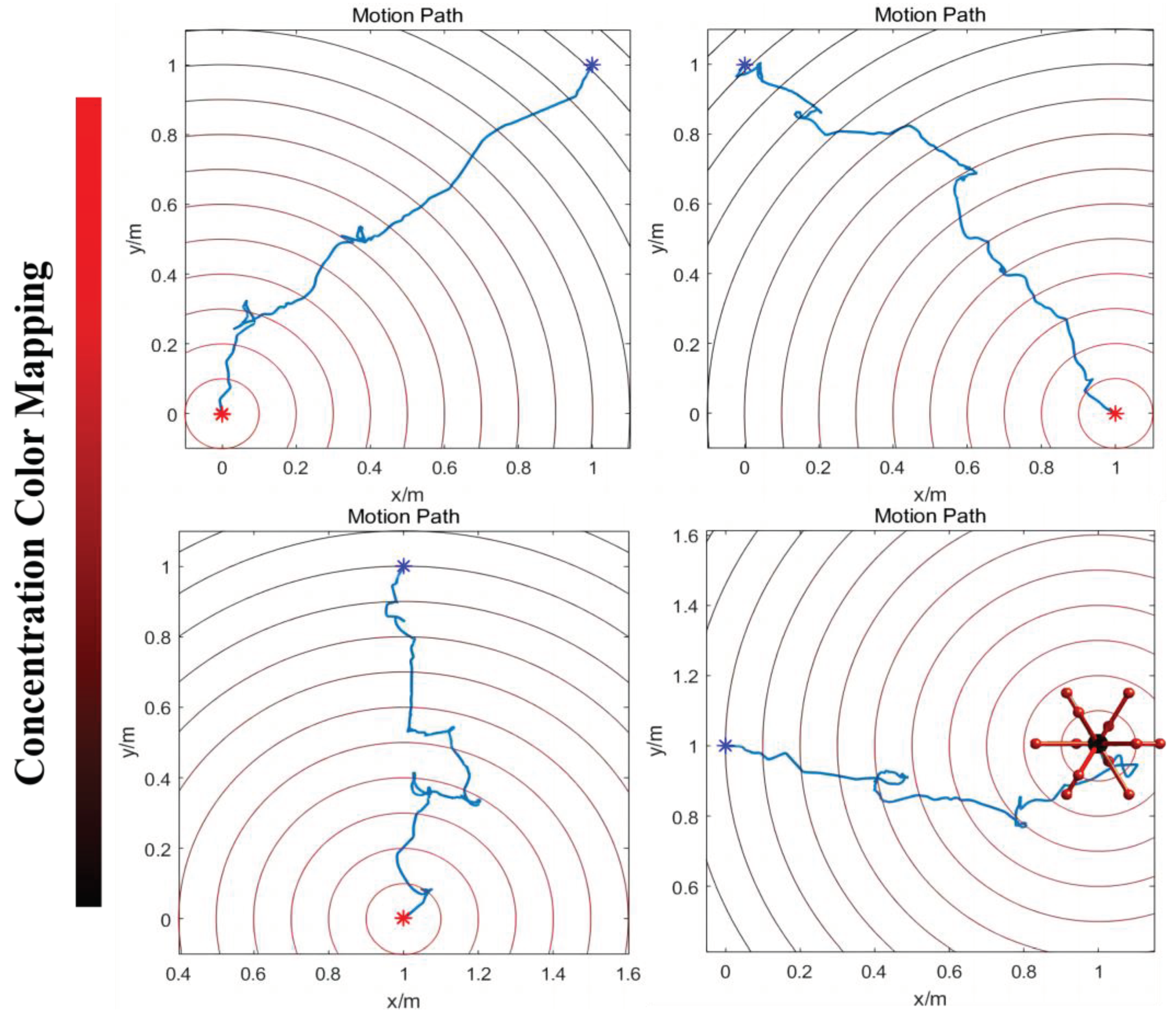
When the robot approaches the target point, the concentration of ‘food’ increases, leading to a rise in the current that exceeds the threshold required to activate the motor neuron VB1. This activation is decoded into movement instructions, prompting the robot to follow the direction of the previous step. Conversely, as the robot moves away from the target point, the concentration of ‘food’ decreases, resulting in the motor neuron VB1 remaining inactive. The resting state is interpreted as the motion command to arbitrarily choose a new direction until it helps the robot to move closer to the target. (The detailed process is shown in Figure 7) Figure 8 displays the simulation results of controlling a robot to move towards various target points from different initial points along four designated directions. The robot may exhibit some spiraling movements, but it effectively reaches the target point by following the direction of increasing gradient. In summary, this method demonstrates that robots can generate autonomous, orienting intelligent behavior similar to C. elegans foraging by utilizing the biological neural circuit to control its policy-making components for the robot. This provides an intelligent control method that enables robots to possess greater biomimetic abilities for intelligent sensing and decision-making, including the ability to navigate to target points in unfamiliar environments without the need for complex sensors. Apart from the existing control technology, the BNN model presents an autonomous and pragmatic approach to directing the robot’s intelligent behavior about the designated missions.

3.2.3. Omnidirectional Locomotion Control

For C. elegans, it can not only decide the moving direction but also manipulate the motion of muscles to make its whole body move along the given direction. Therefore, the second method for a biological neural network to achieve intelligence is to direct the self-organized movement of the robot once the movement instruction has been determined. If the direction of the robot’s movement is determined, joint motion is controlled using a BNN model, inspired by the control of C. elegans’ muscles via motor neurons to generate movement. Thus, it is also possible and justifiable to utilize the motor neuron output from biological neural networks to control the joint motion, which in this study refers to the extension of the robot’s legs when the direction of movement is predetermined and certain, thereby replacing the inverse kinematics.
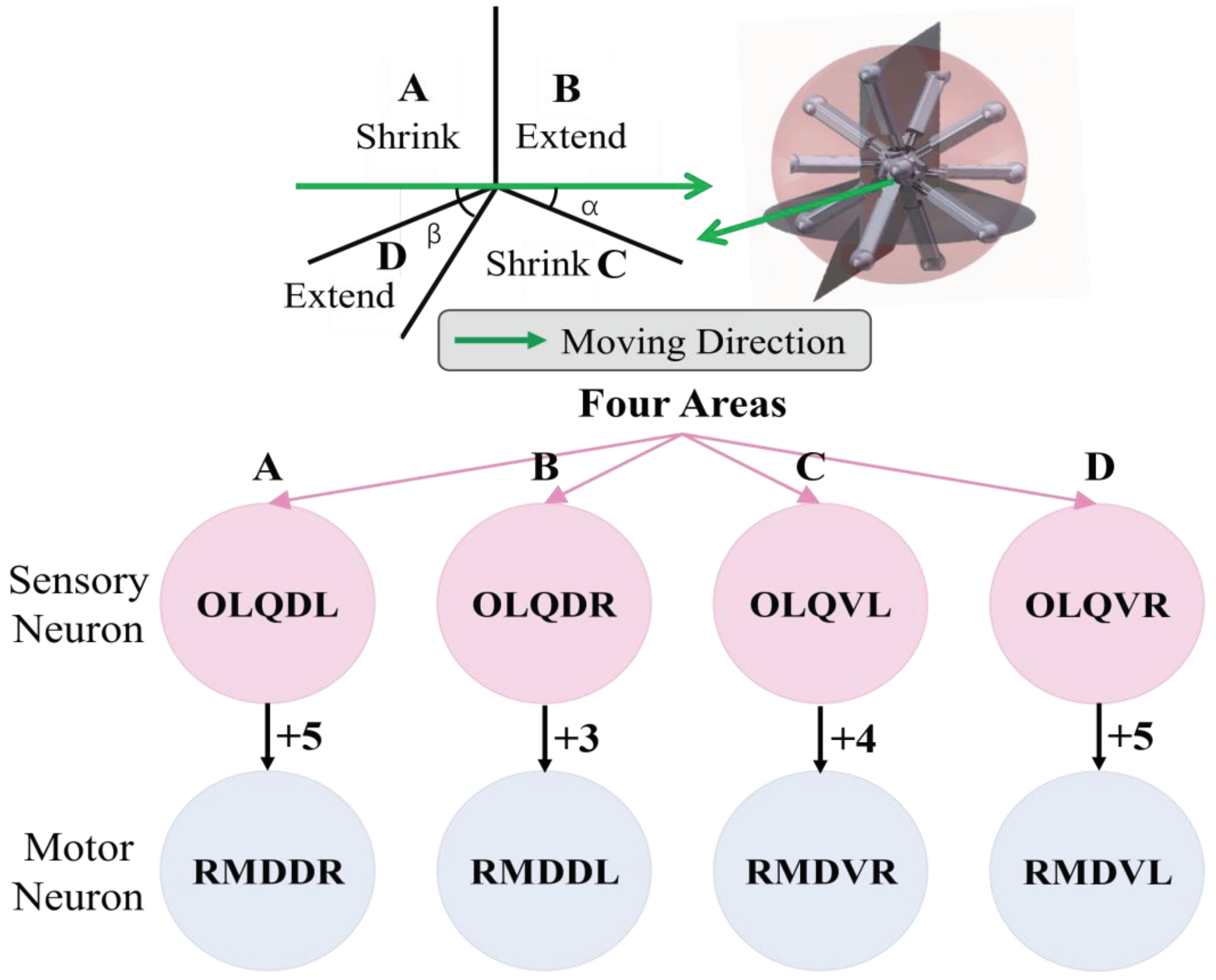
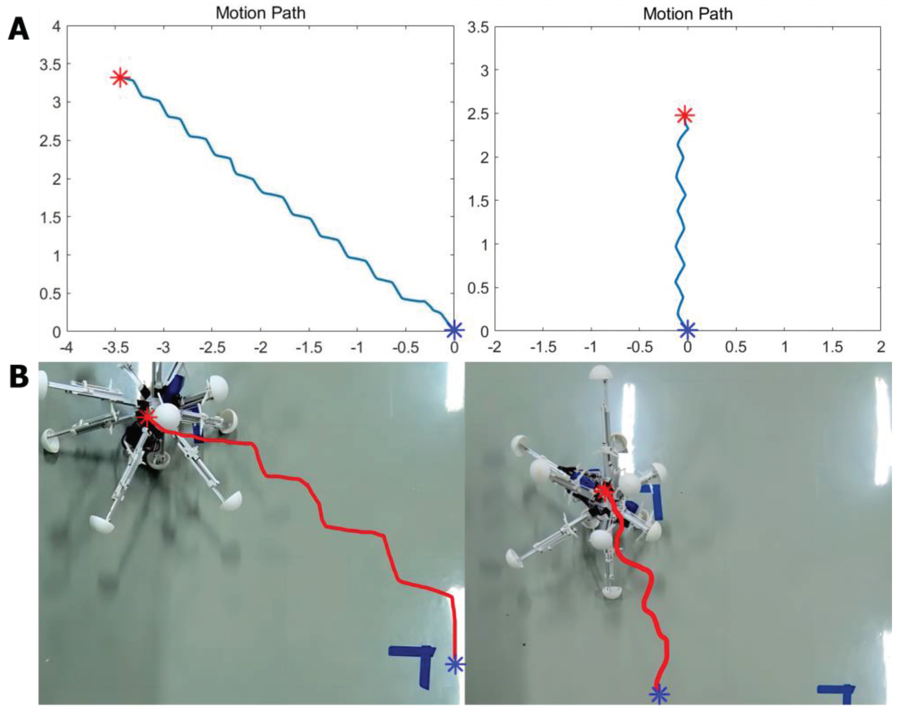
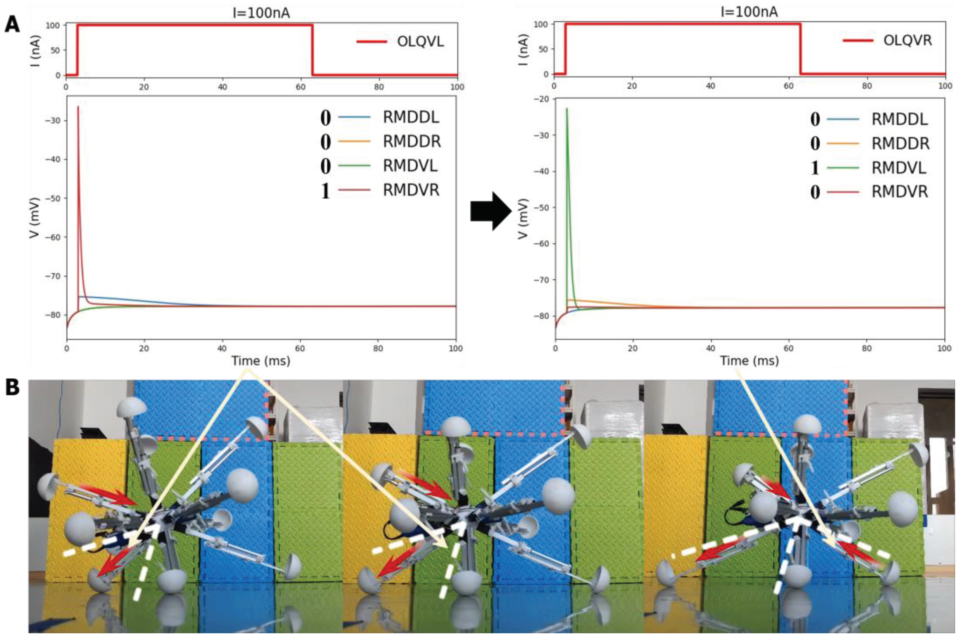
The model for the locomotion of a robot in a specific direction involves dividing the robot into four regions perpendicular to the heading direction plane, as depicted in Figure 9. In Region A, the legs should be shortened, while in Region B, the legs should be elongated. In Region C, the legs should also be shortened, and in Region D, the legs should be elongated. This process will facilitate the gradual movement of the robot through making it roll toward the given direction. For the purpose of BNN control, the biological neural network has been integrated into the control system by establishing a mapping relationship between the four leg regions and the corresponding instructions for leg length adjustment. The four circuits of OLQ sensory neurons and RMD motor neurons have been selected to achieve this objective. The OLQ sensory neurons regulate the head-withdrawal reflex, with the RMD motor neurons serving as their synaptic targets. It is noticeable that the chart summarizes that a particular OLQ neuron regulates an individual RMD motor neuron, as per simulation outcomes without oscillation. Specifically, OLQDL controls RMDDR only, OLQDR controls RMDDL only, OLQVL controls RMDVR only and OLQVR controls RMDVL only (Consistent with Figure 12A). The robot simulation environment enables the derivation of the leg’s corresponding region. Then the current stimuli of four OLQ neurons encode the four regions, and the output of four RMD motor neurons can decode the length change of legs in the corresponding regions. (Refer to Figure 12 for precise details.) To activate these sensory neurons, increase the stimulation current beyond the stimulation threshold, as shown in Chart 1. The legs of regions B and D stretch only if RMDDL and RMDDR are activated. If RMDVL and RMDVR are activated, the legs in regions A and C should shorten. Then the robot can move incrementally in a particular direction using this control method. The study tested linear movement in directions of 0, 45, 90, and 135 degrees. The results indicate that the robot moved effectively in the simulation. Figure 11A illustrates the simulation and experimental results for movements at 90 and 135 degrees. It can be concluded that the robot successfully achieved a generalized self-controlled motion in a specific direction in both simulation and experimental environments.

3.3. Experiment Validation of BNN Control

In total, the two controlling mechanisms can be obtained from the simulation results of methods containing the applicable encoder and decoder between the BNN system and the robot system. It is concluded in the simulation that the BNN model can not only help the robot make direction but also control its self-locomotion. The two different mechanisms are specifically aimed at the various mission fields and control targets in terms of the robot control step. As a result, the two mechanisms can be combined sequentially to accomplish the whole closed-loop control for the intelligent ‘foraging’ behavior of the robot. (Shown in Figure 10 is the closed-loop control description) Moreover, to test and verify the feasibility and performability of using the biological neural network to control the robot in practice, experiments aiming at exhibiting movement results were carried out which focused on the self-locomotion control part. Firstly, to realize the data communication between BNN model platform and MCU installed on the robot to give it moving instructions in real-time, the remote serial communication module of the central panel of the robot is used in experiments. Specifically, the experiment aimed to validate the self-locomotion control for moving in a straight line similar to the former simulation. The signal of length changing for every leg received from the BNN simulation model is output to the panel directly to control the electric motor of every leg. Simultaneously, the leg region dividing information is also transmitted to the BNN simulation model remotely to encode as the input for the sensory neurons. Setting certain locomotion directions for the robot which are 135 degrees and 90 degrees, the experiment results show that the robot can move along the demanding direction successfully. The entire movement is recorded and the video-based moving path is plotted. According to Figure 11, when compared to the simulation environment where the robot demonstrates high accuracy in moving along the line, the physical robot is able to move in a basic directional manner during real experiments, as evidenced by the plotted trace. Although not as smooth and precise as the expected target, the experiment verifies the feasibility of using a biological neural network to control the intelligent self-controlled behavior of the robot moving in a straight line.
The experiment also recorded the specific process of the leg motions of four districts when the robot moved in a particular direction, as shown in Figure 12B. This reveals that the robot’s leg movement strictly adheres to the basic four-region rule which is controlled by the particular circuit OLQ-RMD containing four respective control circuits in the BNN model, enabling the entire robot to move in the desired direction. The detailed process of the moving state of each leg derived from the four corresponding motor neurons’ responding voltage features in the circuit is also shown in Figure 12A&B. For instance, the leg movement in Region D is controlled by the OLQVL-RMDVR circuit, which can be elaborated that: when adding the input current to sensory neuron OLQVL for legs in Region D, only the motor neuron RMDVR is activated and that corresponds to the extension motion of the legs in Region D. However, when it comes to the Region C, the input current is stimulated to the sensory neuron OLQVR, then only the motor neuron RMDVL is activated which determines the shortening behavior of the corresponding legs in Region C. The results demonstrate that the BNN model could effectively control the robot’s locomotion by integrating the discovered characteristic of given circuits in the whole-brain model with the robot’s kinematic joint motion, which is essential for robot ontology locomotion control. They also indicate the effective and accurate real-time control of the robot by the BNN model, which holds significant promise for the prospective deployment of the BNN model in practical applications.

4. Discussion

In this study, we completed a whole-brain network model of C. elegans and designed BNN control method to illustrate the BNN’s control ability and dynamic characteristics and principles by applying the BNN model to the robot control system in a closed-loop. In C. elegans’ whole-brain neural network, sensory neurons activate certain motor neurons specifically in discovered functional circuits, which also serve as the control center for the robot. Various circuits are utilized to control the robot in terms of different control targets or steps through combining the specific mechanisms and considering the particular moving features of the robot. The electric response of motor neurons is recorded and encoded to variables, including digital robot instructions for moving direction or continuous joint movement. The physical sensing or proprioception information of the robot such as the distance to ‘food’ or the leg region is encoded to the input for the BNN model. Then the BNN control system connects to the numeric simulation platform of the robot through designed encoding and decoding method. The method utilizes both the control characteristics of the whole-brain network of C. elegans and the locomotion properties of the robot, causing a deeper-level syncretic robotics control based on the biological neural network with high-performing intelligence completeness.
As a conceptual study, the results exhibit the efficiency of BNN in controlling the intelligent behaviors of a robot, and the behavior pattern relies on specific network configurations and functional circuits. By adopting the circuits of BNN directly (no training required), simple moving control of the robot can be realized on our numerical platform and then migrated to the experimental platform. By applying the whole-brain biological neural network method proposed in this study, the robot can realize the autonomous motion of moving toward an unknown target point using only a single local sensor. This is because the biological controlling mechanism enables the robot to explore the environment purely based on local experiences rather than using absolute location coordinates. Consequently, the research indicates that BNN possesses the potential to improve the robot’s intelligence in mobility. As the preliminary research, this paper demonstrates a way to control multi-legged robots using BNN, which is implemented in a virtual platform, and verified in an experimental platform.

4.1. Contributions and Defect

Here, we present a systematic and innovative methodology for applying the whole-brain model of biological neural network to the robotics control through the biological intelligence control mechanism. Our research identifies two main contributions. Firstly, we develop a real-time whole-brain network model that simulates the computational process occurring in the biological neural activities, incorporating HH model and synapse transmission based on theoretical modelling. The simulation model serves as an integral platform for visualizing neuronal electrical activities and analyzing the dynamic implementation principles corresponding to different behaviors exhibited by C. elegans, including specific control circuits and its dynamical characteristics illustration. Additionally, the whole simulation model is made open-source to facilitate future exploration and extension beyond microscopic level to generate a more precise and comprehensive simulation. Secondly, leveraging the intelligence control capabilities inherent in neural networks, we demonstrate and validate the intelligent performance of C. elegans’ whole-brain neural network through the real scientific robot control simulation and experiments. Our simulation platform of the whole-brain model is integrated with robot control via applicable designing mechanisms and corresponding encoding and decoding methods. This aspect of the study introduces a novel and appropriate system for utilizing a biological whole-brain model to confer its intelligent control capabilities to robots, thereby offering a rational validation of the feasibility of using BNN model to control robotics and generate intelligent behaviors, in contrast to previous methodologies such as PID control and artificial neural network methods.
The meaning for studying the whole-brain model of the creature is profound, which is not only limited in the neuroscience itself but the intelligent implementation mechanism of the biological neural network behind the creature’s complicated behaviors. Therefore, this study not only builds a whole-brain model, but concentrates on how to combine the unique control methodology of the neural model to the robotics to give guidelines on bio-mimic intelligent control based on robotics. In future, neuroscience and artificial intelligence can be two interdisciplinary subjects that are both beneficial to each other to establish a more efficient, advanced, agile and robust control system for autonomous agents’ intelligence realization [59]. And the BNN control can have better performance when applying it to the scientific robot control through the study in the subsequent stage.
Simultaneously, there are few disadvantages of this study. In BNN, the training and learning of the network happens continuously during the whole creature’s natural activities, containing the synapse connection weight changes and synapse connecting and breaking. [60] The detailed learning rules in BNN is complicated and difficult to realize, so the research did not consider the learning process of the network. Because the BNN network changes relatively stable in the different growth stages [60], the research completed an intact biological whole-brain neural model referred to the existing data and parameters extracted from the adulthood of C. elegans [61], which also ensures the accuracy of the model. And we designed a closed-loop bio-mimic robot control aiming at this model despite ignoring the learning simulation of the network model. For future prospects, the learning methods of the BNN model and the limitation of combining the BNN control system with the robot at a deeper level will be studied in order to reach higher integration of BNN-inspired intelligent control. Systematic methods of searching efficient control circuits in a biological neural network should also be studied in the future.

4.2. Result Analysis

Towards two control targets, the orientating control which is making the robot move to a target point and the self-locomotion control that is the robot joint motion, the moving outcomes are both satisfying based on the BNN control inspired by the C. elegans’ behaviors. For the control mission of moving to the target point, the frequently-used method is the path planning built on the ANN control. However, according to the existing experiment done by the team [48], it is necessary to train the artificial neural network for a much longer time, containing the network structural parameters and variables, to own the excellent performance. But for the whole-brain neural network, it is particularly the specified and certain control circuits that could enable the robot orientating control with the high efficiency. While in some circumstances, the precision of BNN control is lower than well-train ANN control, the exploration manifestation and adaptivity is much higher than ANN, which means whole-brain bio-mimic control is totally referential. Especially aiming at the unknown environment which requires the robot having good self-adaption and learning ability when lacking the navigation and sensor signals, the BNN model could help the robot go to the target by exploring step by step, just being similar to the C. elegans’ foraging behavior.
Moreover, BNN control could not only help the robot to manipulate intelligent control task, but also enable the self-locomotion control. This signifies that aiming at an autonomous agent such as robot, BNN also owns the ability to drive its self-motion which is similar with the creature itself. Compared with the robot inverse kinetics control [49], the BNN control to let the robot move adhering the giving instruction could complete this part and its performance is quite equal to the current control ways. Although at present stages, the BNN cannot control the robot by using only one single simulation that is connecting external stimuli or direction to the joint motion directly just by one-time computation of circuits, but the simulation and experiment results of this study demonstrate that the BNN completely possess the capability to control a scientific robot through rational encoding and decoding designing. For future prospects, no matter what feature does the robot have, the whole-brain neural network model could be combined more perfectly with the robot control in a closed-loop to generate the robot’s more intelligent and bionic behaviors in an efficient way. Therefore, it is significant to apply a whole-brain biological neural model to the robotic control to observe its unique performance instead of using conventional control methods to give inspiration and demonstration for BNN control capability.

Supplementary Materials

The following supporting information can be downloaded at: https://github.com/HuKangxin/C.-elegans-whole-brain-neural-network-building-and-simulation, Figure S1: Pictures/Figure S1; Figure S2: Pictures/Figure S2; Table S1: Tables/Table S1; Table S2: Tables/Table S2; Video S1: Videos/Video S1; Video S2: Videos/Video S2; Video S3: Videos/Video S3; Video S4: Videos/Video S4; Video S5: Videos/Video S5.

Author Contributions

Conceptualization: Kangxin Hu, Dun Yang, Qingyun Wang, Hexi Baoyin, Yang Yu; Data curation: Kangxin Hu, Yu Zhang, Fei Ding; Formal analysis: Kangxin Hu, Dun Yang, Fei Ding; Software: Kangxin Hu, Yu Zhang, Fei Ding; Experiment: Kangxin Hu, Fei Ding; Supervision: Yang Yu; Visualization: Kangxin Hu; Funding acquisition: Yang Yu; Writing—original draft: Kangxin Hu; Writing—review & editing: Kangxin Hu, Yu Zhang, Fei Ding, Qingyun Wang, Yang Yu

Funding

Please add: This research was funded by the financial support provided by the National Natural Science Foundation of China Grants No. 12272018.

Institutional Review Board Statement

Not applicable.

Data Availability Statement

We encourage all authors of articles published in MDPI journals to share their research data. In this section, please provide details regarding where data supporting reported results can be found, including links to publicly archived datasets analyzed or generated during the study. Where no new data were created, or where data is unavailable due to privacy or ethical restrictions, a statement is still required. Suggested Data Availability Statements are available in section “MDPI Research Data Policies” at https://www.mdpi.com/ethics.

Conflicts of Interest

The funders had no role in the design of the study; in the collection, analyses, or interpretation of data; in the writing of the manuscript; or in the decision to publish the results.

References

  1. Dorkenwald, S. , et al., Neuronal wiring diagram of an adult brain. bioRxiv, 2023: p. 2023.06. 27.546656.
  2. Deco, G.; Tononi, G.; Boly, M.; Kringelbach, M.L. Rethinking segregation and integration: contributions of whole-brain modelling. Nat. Rev. Neurosci. 2015, 16, 430–439. [Google Scholar] [CrossRef] [PubMed]
  3. Cakan, C.; Jajcay, N.; Obermayer, K. neurolib: A Simulation Framework for Whole-Brain Neural Mass Modeling. Cogn. Comput. 2021, 15, 1132–1152. [Google Scholar] [CrossRef]
  4. Mueller, J.M.; Ravbar, P.; Simpson, J.H.; Carlson, J.M. Drosophila melanogaster grooming possesses syntax with distinct rules at different temporal scales. PLOS Comput. Biol. 2019, 15, e1007105. [Google Scholar] [CrossRef] [PubMed]
  5. Hebert, L.; Ahamed, T.; Costa, A.C.; O’shaughnessy, L.; Stephens, G.J. WormPose: Image synthesis and convolutional networks for pose estimation in C. elegans. PLOS Comput. Biol. 2021, 17, e1008914. [Google Scholar] [CrossRef]
  6. Mujika, A.; Leškovský, P.; Álvarez, R.; Otaduy, M.A.; Epelde, G. Modeling Behavioral Experiment Interaction and Environmental Stimuli for a Synthetic C. elegans. Front. Neurosci. 2017, 11, 71. [Google Scholar] [CrossRef]
  7. Lechner, M.; Hasani, R.; Amini, A.; Henzinger, T.A.; Rus, D.; Grosu, R. Neural circuit policies enabling auditable autonomy. Nat. Mach. Intell. 2020, 2, 642–652. [Google Scholar] [CrossRef]
  8. Sarma Gopal P., L. C.W., Portegys Tom, Ghayoomie Vahid, Jacobs Travis, Alicea Bradly, Cantarelli Matteo, Currie Michael, Gerkin Richard C., Gingell Shane, Gleeson Padraig, Gordon Richard, Hasani Ramin M., Idili Giovanni, Khayrulin Sergey, Lung David, Palyanov Andrey, Watts Mark and Larson Stephen D, OpenWorm: overview and recent advances in integrative biological simulation of Caenorhabditis elegans. PHYLOSOPHICAL TRANSACTIONS OF THE ROYAL SOCIETY B, 2018. 373.
  9. Black, L. A Worm’s Mind In A Lego Body. 2014; Available from: https://www.i-programmer.info/news/105-artificial-intelligence/7985-a-worms-mind-in-a-lego-body.html.
  10. Gingell, S. and T. elegans robot. 2019.
  11. Deng, X.; Xu, J.-X.; Wang, J.; Wang, G.-Y.; Chen, Q.-S. Biological modeling the undulatory locomotion of C. elegans using dynamic neural network approach. Neurocomputing 2016, 186, 207–217. [Google Scholar] [CrossRef]
  12. Yin, X.; Noguchi, N.; Choi, J. Development of a target recognition and following system for a field robot. Comput. Electron. Agric. 2013, 98, 17–24. [Google Scholar] [CrossRef]
  13. Tsalik, E.L.; Hobert, O. Functional mapping of neurons that control locomotory behavior in Caenorhabditis elegans. J. Neurobiol. 2003, 56, 178–197. [Google Scholar] [CrossRef]
  14. Schafer, W.R. , Mechanosensory molecules and circuits in C. elegans. Pflügers Archiv-European Journal of Physiology, 2015. 467: p. 39-48.
  15. Lüersen, K.; Faust, U.; Gottschling, D.C.; Döring, F. Gait-specific adaptation of locomotor activity in response to dietary re-striction in Caenorhabditis elegans. J. Exp. Biol. 2014, 217, 2480–2488. [Google Scholar]
  16. Gray, J.M.; Hill, J.J.; Bargmann, C.I. A circuit for navigation in Caenorhabditis elegans. Proc. Natl. Acad. Sci. 2005, 102, 3184–3191. [Google Scholar] [CrossRef]
  17. Riddle, D. , et al., Introduction: The neural circuit for locomotion. C. elegans II, 1997.
  18. Qi, W. , et al., Design and Experiment of Complex Terrain Adaptive Robot Based on Deep Reinforcement Learning. Journal of Astronautics, 2022. 43(9): p. 1176-1185.
  19. Venkataraman, A. and K.K. Jagadeesha, Evaluation of inter-process communication mechanisms. Architecture, 2015. 86: p. 64.
  20. Riddle, D.L. , et al. elegans ii. 1997.
  21. Izquierdo, E.J.; Beer, R.D. Connecting a Connectome to Behavior: An Ensemble of Neuroanatomical Models of C. elegans Klinotaxis. PLOS Comput. Biol. 2013, 9, e1002890. [Google Scholar] [CrossRef]
  22. Sabrin, K.M.; Wei, Y.; Heuvel, M.P.v.D.; Dovrolis, C. The hourglass organization of the Caenorhabditis elegans connectome. PLOS Comput. Biol. 2020, 16, e1007526. [Google Scholar] [CrossRef]
  23. Mohammadi, A.; Rodgers, J.B.; Kotera, I.; Ryu, W.S. Behavioral response of Caenorhabditis elegansto localized thermal stimuli. BMC Neurosci. 2013, 14, 1–12. [Google Scholar] [CrossRef]
  24. Milward, K.; Busch, K.E.; Murphy, R.J.; de Bono, M.; Olofsson, B. Neuronal and molecular substrates for optimal foraging in Caenorhabditis elegans. Proc. Natl. Acad. Sci. 2011, 108, 20672–20677. [Google Scholar] [CrossRef]
  25. Goodman, M.B. and P. Sengupta, How Caenorhabditis elegans Senses Mechanical Stress, Temperature, and Other Physical Stimuli. Genetics, 2019. 212(1): p. 25-51.
  26. Chatzigeorgiou, M.; Bang, S.; Hwang, S.W.; Schafer, W.R. tmc-1 encodes a sodium-sensitive channel required for salt chemosensation in C. elegans. Nature 2013, 494, 95–99. [Google Scholar] [CrossRef]
  27. WormAtlas, A., Z. F., Herndon, L.A., Wolkow, C.A., Crocker, C., Lints, R. and Hall, D.H. (ed.s)., WormAtlas. 2002-2023: http://www.wormatlas.org.
  28. Kaplan, J.M.; Horvitz, H.R. A dual mechanosensory and chemosensory neuron in Caenorhabditis elegans. Proc. Natl. Acad. Sci. 1993, 90, 2227–2231. [Google Scholar] [CrossRef]
  29. Sawin, E.R.; Ranganathan, R.; Horvitz, H. C. elegans Locomotory Rate Is Modulated by the Environment through a Dopaminergic Pathway and by Experience through a Serotonergic Pathway. Neuron 2000, 26, 619–631. [Google Scholar] [CrossRef]
  30. McDonald, P.W.; Hardie, S.L.; Jessen, T.N.; Carvelli, L.; Matthies, D.S.; Blakely, R.D. Vigorous Motor Activity inCaenorhabditis elegansRequires Efficient Clearance of Dopamine Mediated by Synaptic Localization of the Dopamine Transporter DAT-1. J. Neurosci. 2007, 27, 14216–14227. [Google Scholar] [CrossRef]
  31. Wen, Q.; Po, M.D.; Hulme, E.; Chen, S.; Liu, X.; Kwok, S.W.; Gershow, M.; Leifer, A.M.; Butler, V.; Fang-Yen, C.; et al. Proprioceptive Coupling within Motor Neurons Drives C. elegans Forward Locomotion. Neuron 2012, 76, 750–761. [Google Scholar] [CrossRef]
  32. Faumont S, L.T. , Lockery SR., Neuronal microcircuits for decision making in C. elegans. Current opinion in neurobiology, 2012. 22(4):580-91.
  33. Fenyves, B.G.; Szilágyi, G.S.; Vassy, Z.; Sőti, C.; Csermely, P. Synaptic polarity and sign-balance prediction using gene expression data in the Caenorhabditis elegans chemical synapse neuronal connectome network. PLOS Comput. Biol. 2020, 16, e1007974. [Google Scholar] [CrossRef]
  34. Hodgkin, A.L.; Huxley, A.F. A quantitative description of membrane current and its application to conduction and excitation in nerve. J. Physiol. 1952, 117, 500–544. [Google Scholar] [CrossRef]
  35. Nicoletti, M.; Loppini, A.; Chiodo, L.; Folli, V.; Ruocco, G.; Filippi, S. Biophysical modeling of C. elegans neurons: Single ion currents and whole-cell dynamics of AWCon and RMD. PLOS ONE 2019, 14, e0218738. [Google Scholar] [CrossRef]
  36. Kang, L.; Gao, J.; Schafer, W.R.; Xie, Z.; Xu, X.S. C. elegans TRP Family Protein TRP-4 Is a Pore-Forming Subunit of a Native Mechanotransduction Channel. Neuron 2010, 67, 381–391. [Google Scholar] [CrossRef]
  37. Davis, P. , et al., WormBase in 2022—data, processes, and tools for analyzing Caenorhabditis elegans. Genetics, 2022. 220(4).
  38. Wang, J.; Chen, L.; Fei, X. Analysis and control of the bifurcation of Hodgkin–Huxley model. Chaos, Solitons Fractals 2005, 31, 247–256. [Google Scholar] [CrossRef]
  39. Nielsen, M.S. , et al., Gap junctions. Compr Physiol, 2012. 2(3): p. 1981-2035.
  40. Hall, D.H. , Gap junctions in C. elegans: Their roles in behavior and development. Developmental neurobiology, 2017. 77(5): p. 587-596.
  41. Vogel, R.; Weingart, R. Mathematical model of vertebrate gap junctions derived from electrical measurements on homotypic and heterotypic channels. J. Physiol. 1998, 510, 177–189. [Google Scholar] [CrossRef]
  42. Awile, O.; Kumbhar, P.; Cornu, N.; Dura-Bernal, S.; King, J.G.; Lupton, O.; Magkanaris, I.; McDougal, R.A.; Newton, A.J.H.; Pereira, F.; et al. Modernizing the NEURON Simulator for Sustainability, Portability, and Performance. Front. Neurosci. 2022, 16, 884046. [Google Scholar] [CrossRef]
  43. Stephens, G.J.; Johnson-Kerner, B.; Bialek, W.; Ryu, W.S. Dimensionality and Dynamics in the Behavior of C. elegans. PLOS Comput. Biol. 2008, 4, e1000028. [Google Scholar] [CrossRef]
  44. Schwarz, R.F.; Branicky, R.; Grundy, L.J.; Schafer, W.R.; Brown, A.E.X. Changes in Postural Syntax Characterize Sensory Modulation and Natural Variation of C. elegans Locomotion. PLOS Comput. Biol. 2015, 11, e1004322. [Google Scholar] [CrossRef]
  45. Kindt, K.S.; Viswanath, V.; Macpherson, L.; Quast, K.; Hu, H.; Patapoutian, A.; Schafer, W.R. Caenorhabditis elegans TRPA-1 functions in mechanosensation. Nat. Neurosci. 2007, 10, 568–577. [Google Scholar] [CrossRef]
  46. Zhang, F.; Yu, Y.; Wang, Q.; Zeng, X.; Niu, H. A terrain-adaptive robot prototype designed for bumpy-surface exploration. Mech. Mach. Theory 2019, 141, 213–225. [Google Scholar] [CrossRef]
  47. Zhang, F.; Yu, Y.; Wang, Q.; Zeng, X. Physics-driven locomotion planning method for a planar closed-loop terrain-adaptive robot. Mech. Mach. Theory 2021, 162, 104353. [Google Scholar] [CrossRef]
  48. Yang, D.; Liu, Y.; Ding, F.; Yu, Y. Bionic Multi-legged Robot Based on End-to-end Artificial Neural Network Control. 2022 IEEE International Conference on Cyborg and Bionic Systems (CBS). LOCATION OF CONFERENCE, ChinaDATE OF CONFERENCE; pp. 104–109.
  49. Yang, D., Y. Liu, and Y. Yu. A General Locomotion Approach for a Novel Multi-legged Spherical Robot. in 2023 IEEE International Conference on Robotics and Automation (ICRA). 2023.
  50. Xue, M.; Zhu, C. The Socket Programming and Software Design for Communication Based on Client/Server. 2009 Pacific-Asia Conference on Circuits, Communications and Systems (PACCS). LOCATION OF CONFERENCE, ChinaDATE OF CONFERENCE; pp. 775–777.
  51. Akram, M.A.; Nanda, S.; Maraver, P.; Armañanzas, R.; Ascoli, G.A. An open repository for single-cell reconstructions of the brain forest. Sci. Data 2018, 5, 180006. [Google Scholar] [CrossRef]
  52. Towlson, E.K. , et al., Caenorhabditis elegans and the network control framework—FAQs. Philosophical Transactions of the Royal Society B: Biological Sciences, 2018. 373(1758): p. 20170372.
  53. Badhwar, R.; Bagler, G. Control of Neuronal Network in Caenorhabditis elegans. PLOS ONE 2015, 10, e0139204. [Google Scholar] [CrossRef]
  54. Brezina, V.; Orekhova, I.V.; Weiss, K.R.; Dickinson, P.S.; Armstrong, M.K.; Dickinson, E.S.; Fernandez, R.; Miller, A.; Pong, S.; Powers, B.W.; et al. The Neuromuscular Transform: The Dynamic, Nonlinear Link Between Motor Neuron Firing Patterns and Muscle Contraction in Rhythmic Behaviors. J. Neurophysiol. 2000, 83, 207–231. [Google Scholar] [CrossRef]
  55. Hills, T.; Brockie, P.J.; Maricq, A.V. Dopamine and Glutamate Control Area-Restricted Search Behavior inCaenorhabditis elegans. J. Neurosci. 2004, 24, 1217–1225. [Google Scholar] [CrossRef]
  56. Pradhan, S.; Quilez, S.; Homer, K.; Hendricks, M. Environmental Programming of Adult Foraging Behavior in C. elegans. Curr. Biol. 2019, 29, 2867–2879. [Google Scholar] [CrossRef]
  57. Petzold, B.C.; Park, S.-J.; Ponce, P.; Roozeboom, C.; Powell, C.; Goodman, M.B.; Pruitt, B.L. Caenorhabditis elegans Body Mechanics Are Regulated by Body Wall Muscle Tone. Biophys. J. 2011, 100, 1977–1985. [Google Scholar] [CrossRef]
  58. Castellanos, J.A. and J.D. Tardos, Mobile robot localization and map building: A multisensor fusion approach. 2012: Springer Science & Business Media.
  59. Zeng, T.; Si, B. A brain-inspired compact cognitive mapping system. Cogn. Neurodynamics 2020, 15, 91–101. [Google Scholar] [CrossRef] [PubMed]
  60. Baxter, D.A. and J.H. Byrne, Learning rules from neurobiology. The neurobiology of neural networks, 1993: p. 71-105.
  61. Bentley, B.; Branicky, R.; Barnes, C.L.; Chew, Y.L.; Yemini, E.; Bullmore, E.T.; Vértes, P.E.; Schafer, W.R. The Multilayer Connectome of Caenorhabditis elegans. PLOS Comput. Biol. 2016, 12, e1005283. [Google Scholar] [CrossRef] [PubMed]
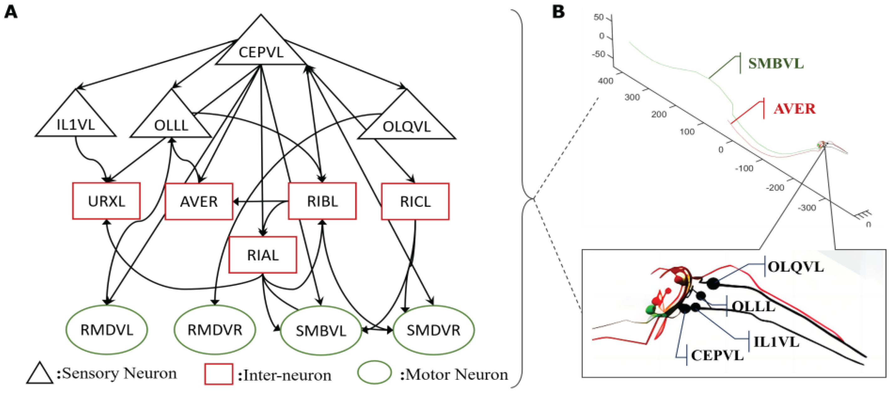
Figure 1. One critical circuit containing sensory neuron CEPVL and a relative part of interneurons and motor neurons. From the visualization diagram of part B, the detailed position of sensory neuron CEPVL interneuron AVER, and motor neuron SMBVL are highlighted, as well as their connections seen from the head illustration with different colors representing different types of neurons, consistent with part A. In part A, every node represents a single neuron. The sensory neuron CEPVL is to sense the stimuli from the head and then propagates to the following interneurons distributed around it and motor neurons distributed along the body to drive muscles to do responding movements, consistent with the morphological structure in part B. Simultaneously, the synapse connecting relationship is shown in part A which is expressed in an arrow. It describes the whole connecting from several sensory neurons signified by the black triangle to the interneurons signified by the red rectangular and the motor neurons signified by the green ellipse.
Preprints 102928 g001
Figure 2. The oscillation phenomenon of the voltage response of the motor neuron under the current stimulation of the corresponding sensory neuron in one specific circuit CEPVL-VA12. The frequency of the active spiking of the motor neurons’ voltage response is getting larger with the current increasing. The sensory neuron for stimulation is CEPVL in the circuit, and the picture illustrates its external current stimuli changing form. The motor neuron we observed is VA12, while the picture shows its responding voltage alteration which has an oscillation phenomenon. The simulation of the circuit is in the whole neural network of C. elegans. This phenomenon containing the spiking frequency changing can be used to do the encoding for relevant continuous variables in robot kinetic system. Meanwhile, a more detailed picture is also shown in Video S1 in Supporting Information.
Preprints 102928 g002
Figure 3. The physical structure of the radial-skeleton robot in this study. (A) shows the integral physical appearance of the robot. (B) shows the detailed configuration including the stretching principle of one leg. (C) shows the moving process for this multi-legged skeleton robot by stretching and shrinking its legs. The detailed instructions can also be read in the former paper. [49].
Preprints 102928 g003
Figure 4. Total hardware control process and system of robot in the experiment. The more detailed description can also be seen in the former paper [49] written by the team.
Preprints 102928 g004
Figure 5. The visualization of voltage response of the whole neural network model under the stimuli acting on the sensory neuron CEPVL. The color change corresponds to the voltage of the neurons having the value changing from -85mV to 0mV, where yellow means the voltage is close to 0mV and black means the voltage is close to -70~-85mV. Therefore, the yellow represents the action potential and the black represents the resting potential. The four pictures showing the voltage change in a moment are extracted in a continuous time. The process is that the neurons go from resting potentials to action potentials and then go back to resting potentials. A more detailed diagram is also shown in Figure S6 in Supporting Information.
Preprints 102928 g005
Figure 6. Encoding and decoding method to connect between the robot system and biological neural network system. The encoding current is derived from the robot sensing information such as its distance to the ‘food’ target point, which will be elaborated in the following part about how to transform the distance to the input current. Once the biological neural network receives the input, it starts to complete the whole-brain network simulation. And the simulation results of the motor neurons will be decoded to the moving variables or the moving command to do the next step’s motion for the robot.
Preprints 102928 g006
Figure 7. The circuit ASHL-VB1 of finding the highest concentration point along the direction of gradient increasing which owns the dynamic characteristics that the motor neuron (output neuron) is activated by the current stimulation of sensory neurons with no oscillation and the control results in robot moving simulations. If the current stimulating the sensory neuron is higher than the threshold, the motor neuron will be activated. If the current is lower than the threshold, the motor neuron will generate no acting potential. The threshold of the current input corresponds to the moving state of the robot. And by simulation, that value of acting current is discovered to be 51nA. Meanwhile, the identification of the activation state of motor neuron VB1 can also be realized by Python programming. From A to B, the picture shows the detailed control mechanism for this method. According to the moving direction signified by a green arrow in the robot simulation picture, if the motor neuron VB1 is activated, the direction in the next step is still following the previous step. However, if the motor neuron VB1 is not activated, which means the robot is further away from the target point, then the robot will be given a new decided direction until the direction helps the robot to move closer to the target. Meanwhile, the whole moving video is shown in Video S3 in Supporting Information.
Preprints 102928 g007
Figure 8. The simulation moving results for the robot to move to the target point that has the highest ‘food’ concentration. On the whole, the robot can move from the initial point to the target while having some spiraling states. Meanwhile, the blue point means the initial point and the red point means the target and the robot simulation is plotted on the two red points. Plus, on the left side of the figure is ‘food’ concentration color mapping. Red means the higher concentration and black means the lower. The experiment uses a unit of one meter. The results show that the robot can move autonomously from the lower ‘food’ concentration point to ‘food’ under the control of the BNN model of C. elegans. Additionally, the moving details are shown in Video S3 in Supporting Information.
Preprints 102928 g008
Figure 9. The design of four specific circuits to control the motion of the legged robot along a determined direction. The detailed process is dividing the robot into four parts by four planes vertical to the moving plane. Like what is shown in the picture, the detailed motion of legs in four parts can be derived by inverse kinetics. The four districts can be exactly corresponding to the four control BNN circuits. The symbol and number between sensory neurons and motor neurons mean the polarity and weight of their synapse connection.
Preprints 102928 g009
Figure 10. The combination of operation mechanism for BNN control system and robot moving system. The physical variables for input encoding could be the ‘food’ concentration changing of robot or the districts of robot legs. And the inputs are mapped with the current stimulation to sensory neurons. After we get the voltage response of motor neurons in model simulation, it will be decoded to the motion instruction or joint variables according to designed missions. Then the robot can do the next step motion. This whole process is closed-loop and continuous in real-time.
Preprints 102928 g010
Figure 11. The simulation and experiment results of robot moving which is controlled by the four-region control mechanism. The shown moving angles are 135 degrees and 90 degrees along the line. In total, the experiment results show only slightly different moving effects compared with the simulation. Blue points mean starting points, and red points mean destination points. The red lines are the plotted moving trace of the robot in the experiments. In part B, the detailed robot moving experiment is also shown in Video S4 in Supporting Information.
Preprints 102928 g011
Figure 12. The detailed stretching motion of the legs of the robot in three continuous steps under the control of BNN of C. elegans. In part A, the two diagram illustrates the responses of the corresponding four motor neurons stimulated by the sensory neuron OLQVL and OLQVR connecting to Regions D and C in the robot dividing regions. The activation state deciding the leg length movements is also labeled in the picture by 0 or 1(1 means that the motor neuron is activated by the circuit and 0 means the resting state). In part B, the red arrows mean the length-changing direction of the legs which are divided by the white lines. The results demonstrate that it follows the four-region rule in view under the corresponding BNN circuit control in the shown leg movements of Regions C and D which are specifically controlled by the OLQVL-RMDVR circuit and OLQVR-RMDVL circuit.
Preprints 102928 g012
Table 1. The values of parameters in the HH model that are constants for every single neuron of the whole-brain model of C. elegans.
Parameters Values
C m 3.1 μ F / c m 2
g ¯ l 0.289 nS
V K -75 mV
V N a 55 mV
V L -84 mV
V C a 45 mV
Table 2. The summary of the found circuits in the whole-brain neural network of C. elegans including corresponding sensory neurons and motor neurons and current stimuli range for activating motor neurons. Moreover, the value range of input current to activate motor neurons is particularly under a given group of parameters in this study which are concluded for encoding and decoding. Most of the sensory neurons and motor neurons are both investigated and verified [25,27]. The relevant data and information of neurons can be found at the WormAtlas [27].
Sensory Neuron (Mechanosensory) Motor Neuron Current Stimuli Value Range (Unit: nA)
ASHL DA, DB, VA, VB, VD, SMB, SMD, RMB, RMD 60- (One action potential only)
ADEL DA, DB, VA, VB, VD 59-64 (Bifurcation Range)
ADER DA, DB, VA, VB, VD 59-68 (Bifurcation Range)
CEPDL DA, DB, VA, VB, VD, SMB, SMD, RMB, RMD 64-111 (Bifurcation Range)
CEPDR DA, DB, VA, VB, VD, SMB, SMD, RMB, RMD 64-91 (Bifurcation Range)
CEPVL DA, DB, VA, VB, VD, SMB, SMD, RMB, RMD 64-111 (Bifurcation Range)
CEPVR DA, DB, VA, VB, VD, SMB, SMD, RMB, RMD 64-85 (Bifurcation Range)
PDEL DA, DB, VA, VB, SMDVL 60-190 (Bifurcation Range)
PDER DA, DB, VA, VB, VD, SMB, SMD, RMB, RMD 60-88 (Bifurcation Range)
OLQDL RMDDR 91- (One action potential only)
OLQDR RMDDL 91- (One action potential only)
OLQVL RMDVR 91- (One action potential only)
OLQVR RMDVL 94- (One action potential only)
Disclaimer/Publisher’s Note: The statements, opinions and data contained in all publications are solely those of the individual author(s) and contributor(s) and not of MDPI and/or the editor(s). MDPI and/or the editor(s) disclaim responsibility for any injury to people or property resulting from any ideas, methods, instructions or products referred to in the content.
Copyright: This open access article is published under a Creative Commons CC BY 4.0 license, which permit the free download, distribution, and reuse, provided that the author and preprint are cited in any reuse.
Prerpints.org logo

Preprints.org is a free preprint server supported by MDPI in Basel, Switzerland.

Subscribe

© 2024 MDPI (Basel, Switzerland) unless otherwise stated