1. Introduction
One of mostly commonly used in machine components includes mechanical clutches. The clutches perform a number of tasks in drive systems, e.g. connecting and disconnecting shafts, overload protection, enabling or improving start-up, and equalizing loads during operation of multi-motor drives. Due to that, perfecting the clutch design is a desirable direction in the development of machines, as it has a significant impact on increasing the durability and improving the functionality of machines. The driving and driven parts of the clutch are connected to each other with a connector – permanently or allowing slippage. Particularly in slipping clutches, a fluid or a magnetic field may act as a connector. Hydraulic clutches whose connector is a fluid are built in either a viscous or hydrodynamic variant [
1,
2,
3]. In typical viscous clutches, the torque is transmitted as a result of friction caused by shear stresses in the working fluid located in the working gap formed by the driving part and the driven part of the clutch [
4,
5,
6,
7]. In classic magnetic clutches, the magnetic field is used to induce an electric current, and thus generate magnetic forces between the torque-transmitting parts of the clutch [
8].
The working fluids used in hydraulic clutches are usually hydraulic oils. However, clutches which use fluids with rheological properties controlled by electric current are already used [
9,
10,
11,
12]. There are two types of the aforementioned fluids: magnetorheological fluids (MR) and electrorheological fluids, wherein the MR fluids are the ones that are used more frequently, due to the fact that the shear stresses obtained in MR fluids are 20 to 50 times higher than in electrorheological fluids [
13]. MR fluids are two-phase mixtures or colloids, which change their rheological properties under the influence of a magnetic field [
14,
15,
16]. The solid phase of the MR consists of particles made of ferromagnetic materials such as cobalt, iron, iron alloys, and oxides of these metals. MR fluids whose solid particles have a diameter of several dozen nanometers are also known as ferrofluids or ferro-colloids. Their liquid phase is usually silicon oil, due to the fact that temperature has little effect on the rheological properties of this oil. MR fluids also contain chemical compounds which prevent solid phase sedimentation and particle aggregation. Apart from clutches, MR fluids are used as working fluids in various machine components [
17,
18], mainly in vibration dampers [
19,
20,
21,
22], electrohydraulic servo control systems [
23,
24], cantilever sandwich beams [
25], and seals [
26]. The main advantages those determine the technical use of these fluids are: the ability to control shear stresses in the fluid using electric current, and the short reaction time of the liquid to a change in the magnetic field (this allows for high dynamics of the controlled component). The relevant literature provides different theories regarding the impact of the rotating magnetic field on the MR fluid placed in the beaker, wherein theoretical considerations apply only to ferro-colloids. The forces, which influence the phenomena occurring in a ferro-colloids placed in a rotating magnetic field, include magnetic interaction, intermolecular attraction, surface tension, centrifugal force, viscosity, friction and gravity. The magnetic field is determined by the three following vector quantities: magnetic induction
, magnetic field intensity
and magnetization
. These three are related by the dependency
, where the coefficient
signifies the magnetic permeability of free space.
According to the authors of publications [
27,
28], there are two possible ways that magnetization
of ferro-colloid particles reacts to a rotating magnetic field. These two ways are called the Neel mechanism and the Brawn mechanism. For smaller particles which cannot freely rotate within the fluid due to a greater resistance to movement, the magnetization vector rotates inside the particle. This manner of magnetization is called the Neel mechanism. The Brawn mechanism is related to the Brawn motion of solid particles within a fluid. The Neel mechanism occurs if the colloid consists of solid iron particles with a diameter smaller than 0.0085 μm, while the Brawn mechanism occurs when the colloid consists of solid iron particles with a diameter larger than 0.0085 μm. However, it should be noted that this does not represent a general rule. For ferro-colloid solid particles made of cobalt, the limiting particle diameter is 0.004 μm. Under the influence of a rotating magnetic field, larger ferro-colloid particles rotate freely within the fluid, with an angular velocity
ω of the rotation of the magnetic field. The base fluid in the immediate vicinity of the solid particles rotates as well, so each ferro-colloid particle becomes the center of a microscopic vortex. All particles rotate at the same angular velocity
ω, which means that there is no macroscopic movement of the ferro-colloid, and only the outermost fluid particles (at the walls of the beaker) move. The rotating magnetic field affects the macroscopic motion of the ferro-colloid only when the magnetic field is non-uniform. However, for a larger volume of ferro-colloid to move, additional conditions must be met regarding the diameter and concentration of solid particles and the viscosity of the base fluid. A similar interpretation of the influence of the rotating magnetic field on the movement of ferro-colloid is presented in article [
29]. In a stationary magnetic field, the magnetization vector
is collinear with the magnetic field intensity vector
. During the rotation of the magnetic field, the collinearity of these vectors can also be maintained for small solid ferro-colloid particles. Then, the magnetization vector
rotates freely with the solid particles in the base fluid. On the other hand, in large particles, when the magnetic field intensity vector
rotates with angular velocity
ω, the magnetization vector
remains behind the vector
and is shifted by a certain lag angle. As a result of the lag angle, the vector product
has a value other than zero and creates a torque
M influencing the motion of particles in the rotating magnetic field. The solid particles rotate slower than the magnetic field because their movement is inhibited by the viscous forces of the fluid.
The authors of publication [
30] proposed the "magnetic pole model". Their assumption is that each volume element in a homogenous ferro-colloid can be assigned a magnetization vector
dependent on the concentration of solid particles and the lag angle α, in relation to the rotating magnetic field
dependent on the resistance caused by viscous forces. In the presence of a rotating magnetic field, the torque (resulting from vector product
) induces rotation in the volume element, causing it to rotate with the rotation speed of the magnetic field
ω. However, for bulk rotation of the ferro-colloid to occur, there must be in homogeneities in the ferro-colloid in the value
or the angle
α. Then, a pair of mutually interacting magnets are created. As a result, one of these magnets pulls the other, which causes the whole volume of the ferro-colloid to rotate in the beaker with the speed of
ω. During experimental research [
29,
30,
31,
32,
33] on the behavior of various ferro-colloids placed in a beaker affected by a magnetic field rotating with an angular velocity
ω, it has been found that ferro-colloid solid particles rotate within the base fluid with an angular velocity of
ω. This causes the base fluid to rotate around these particles at a speed lower than the angular velocity
ω. Depending on the test conditions and the existing in homogeneities: the magnetic field, magnetization, particle concentration, friction coefficient and viscosity of the base fluid, it is possible that the entire ferro-colloid volume will move with an angular velocity lower than
ω. Wherein, the ferro-colloid may rotate in the
ω direction, against the
ω direction, or macroscopic vortices may occur. The rotation speed of the ferro-colloid depends on the angular velocity
ω, the magnetic field intensity, the location of the magnetic field, the size of solid particles and their magnetization. A thin ferro-colloid ring may appear near the beaker’s wall, rotating at an angular velocity much lower than
ω. After adding an immiscible fluid to the ferro-colloid, one could observe the formation of a convex or concave meniscus as a result of the rotation of the magnetic field.
The effect of a rotating magnetic field on ferro-colloids is confirmed in work [
33], which examines the behavior of a ferro-colloid drop placed in an alcohol solution with simultaneously applied rotating and DC axial magnetic fields. Observing the placement of ferrofluid in a fluid reveals various distinctive patterns. The publications [
34,
35] present research results on the behavior of ferro-colloids under the influence of a rotating magnetic field, utilizing a Brookfield rheometer. The rheometer spindle is immersed in a stationary beaker filled with a ferro-colloid; the beaker is affected by a rotating magnetic field generated by the stator winding of a three-phase induction motor. It has been found that the torque acting on the rheometer spindle depends on the angular velocity of rotation of the magnetic field, the magnetic field intensity and the magnetization of the ferro-colloid particles. The study [
29] also considers the possibility of increasing the efficiency of a hydrodynamic torque converter filled with ferro-colloid as a working fluid, placed inside the winding stator of a three-phase induction motor.
However, as expected, there was no increase in the angular velocity of the output shaft of the hydrodynamic torque converter as a result of the impact of the rotating magnetic field on the ferro-colloid. The article introduces a novel construction concept for a hydraulic clutch (HCMR) incorporating a MR fluid This concept involves the application of a rotating magnetic field to induce the rotation of the MR fluid, consequently transmitting torque through friction against the beaker walls. The developed HCMR is at the “technology demonstration” stage.
4. Conclusions
On the basis of the considerations regarding HCMR, the following general conclusions have been drawn:
(1) The literature review shows that the rotating magnetic field can cause macroscopic rotation of the MR fluid with a rotational speed lower than the rotational speed of the magnetic field. Whether such a movement will occur and what its direction will be depends on a number of factors related to the properties of the MR fluid and operating conditions. Due to the complexity of the phenomena occurring, no single model has been developed so far to explain the causes of rotation of the MR fluid in a rotating magnetic field. Most authors believe that the shape of the model is significantly impacted by the inhomogeneities in the MR fluid affected by the rotating magnetic field.
(2) The impact of the magnetic field on the rheological properties of MR fluids with varying sizes of iron particles, assessed using a customized rheometer with a magnetic device, can be accurately determined for MR fluids with iron particles having diameters not exceeding 6.5 μm. Iron particles with a larger diameter exhibit a stronger attraction towards the poles of the electromagnet situated outside the measuring gap. This results in a reduction of the iron content in the vicinity of the rheometer spindle, thereby limiting the influence of the magnetic field on the measured torque. Therefore, other measurement methods should be sought for MR fluids with larger iron particles.
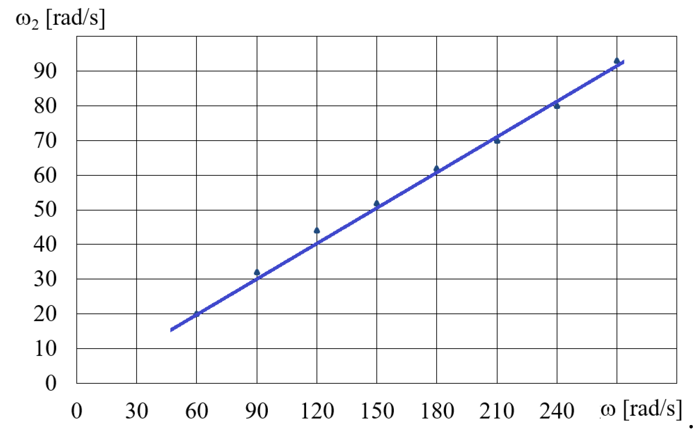
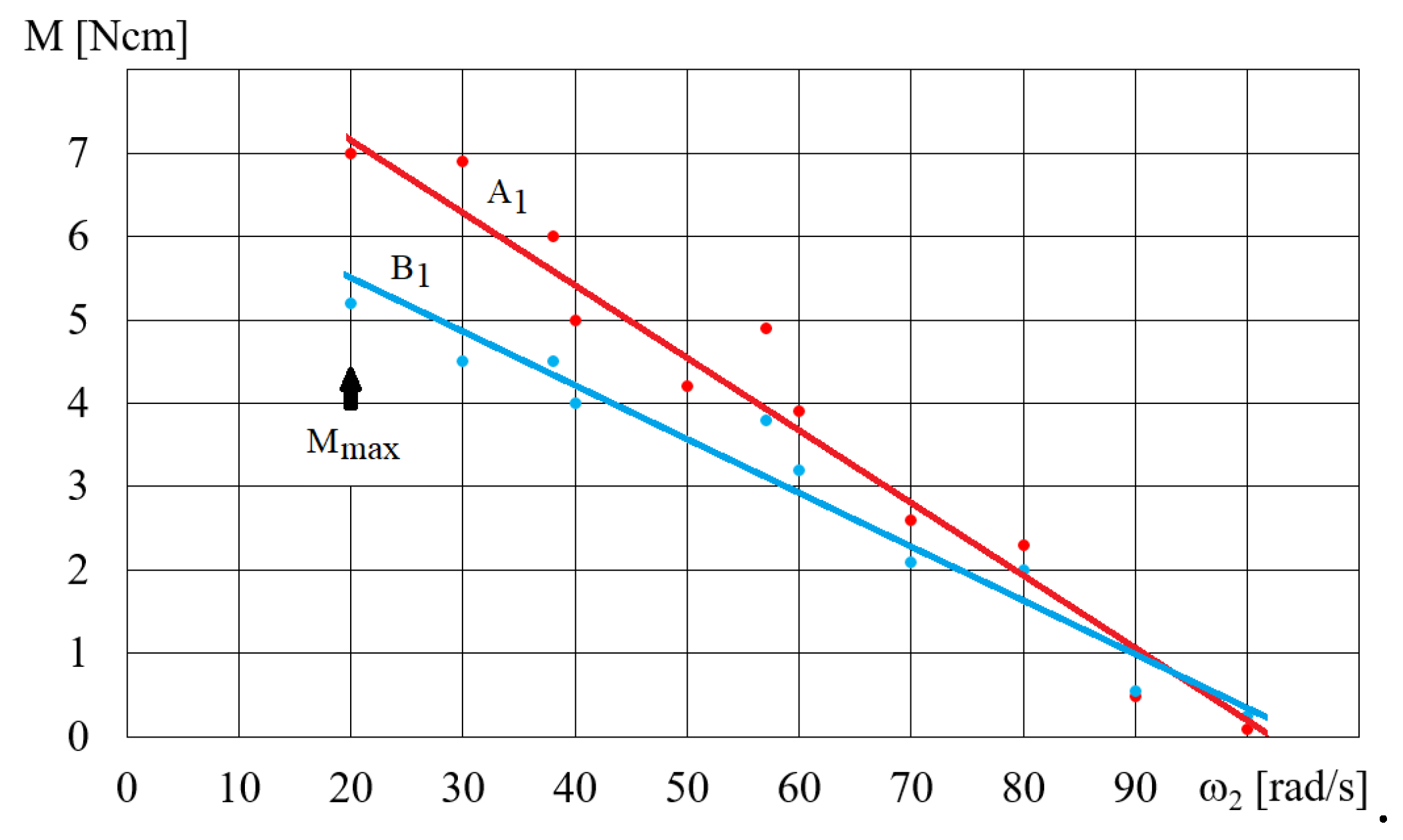
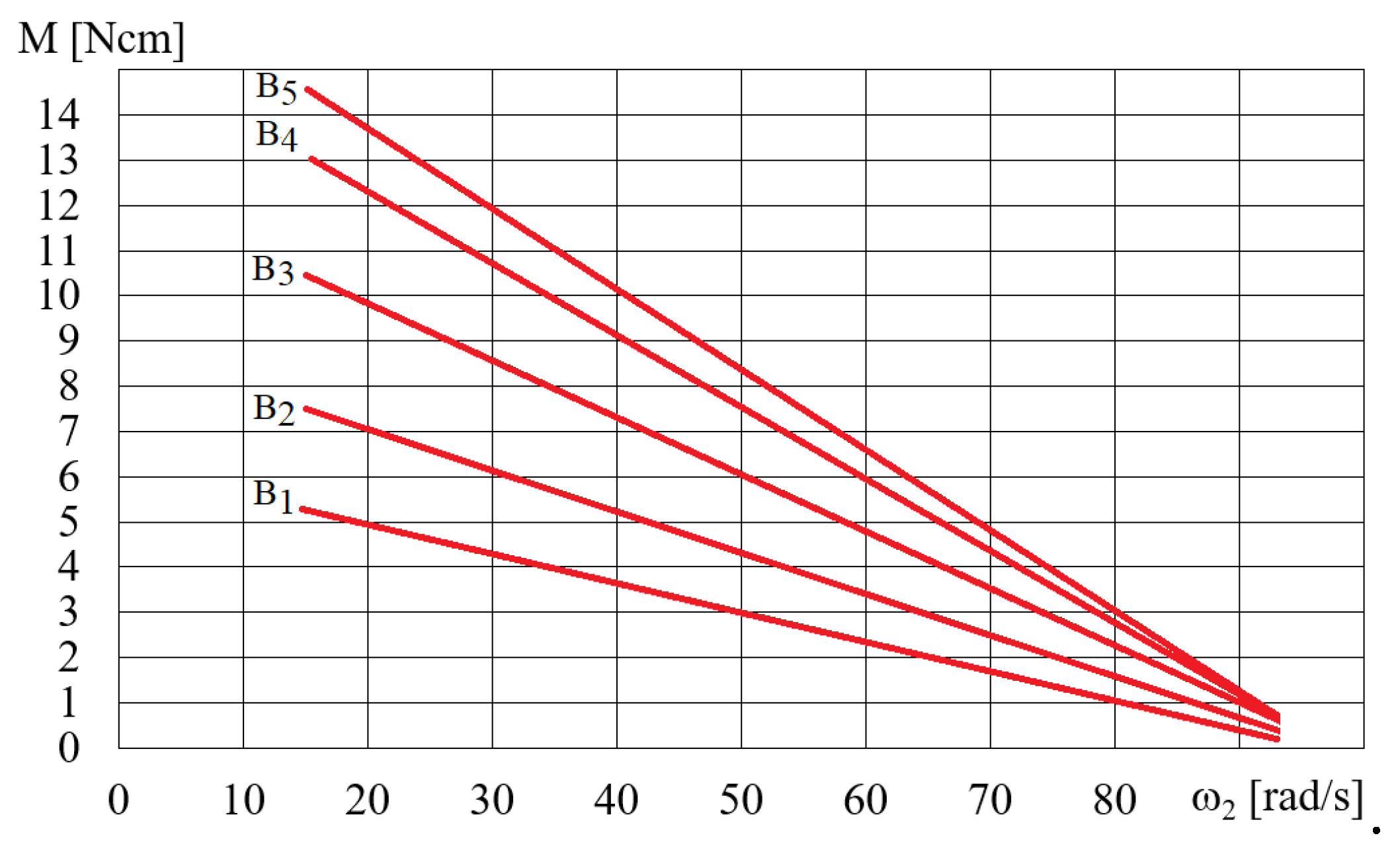
(3) In the absence of a load on the HCMR output shaft, the angular velocity of the beaker containing the MR fluid exhibits a linear dependence on the angular velocity of the magnetic field. However, during shaft braking, the torque transmitted by the clutch increases with higher angular velocity of the magnetic field and lower angular velocity of the beaker. The highest torque occurs for MR fluids with the highest iron content and solid particles with dimensions ranging from 3.5 to 6.5 μm.
(4) HCMR characteristics are similar to characteristics of eddy current clutches and result mainly from the combined action of magnetic and centrifugal forces on the MR fluid. The solid particles of the MR fluid are attracted by the rotating magnetic field and simultaneously pressed against the walls of the beaker, mainly due to the influence of centrifugal forces. The rotational motion of the beaker is induced by the friction force generated due to the applied pressure. The magnitude of the friction force, which propels the rotation of the beaker, increases with the greater difference between the rotational speed of the magnetic field and that of the beaker. The viscous-plastic properties of the MR fluid cause the solid particles of the MR fluid to be slower than the rotation of the magnetic field.
It is finally remarked here that further research regarding HCMR should aim to design, construct and test a clutch prototype and to select MR fluids with the optimal size and shape of solid particles so that the proposed system can be applicable to several types of the hydraulic control systems in real environment subjected to various uncertainties such as time-varying temperature.
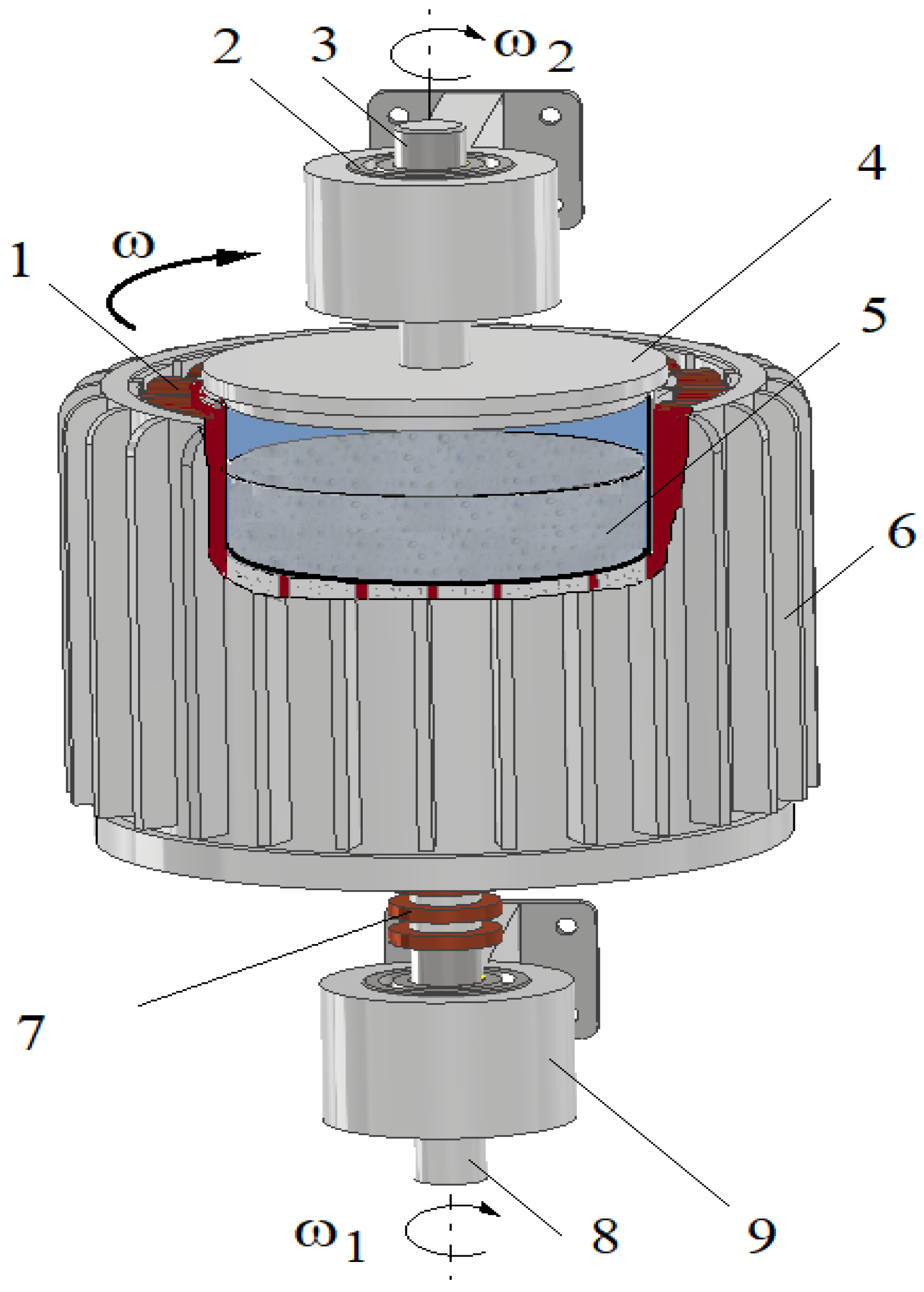
Figure 1.
HMCR construction scheme: 1 – coil, 2 – bearings, 3 – output shaft, 4 – beaker, 5 – MR fluid, 6 – stator of a three-phase induction motor, 7 – slip rings, 8 – input shaft, 9 – bearings housing.
Figure 1.
HMCR construction scheme: 1 – coil, 2 – bearings, 3 – output shaft, 4 – beaker, 5 – MR fluid, 6 – stator of a three-phase induction motor, 7 – slip rings, 8 – input shaft, 9 – bearings housing.
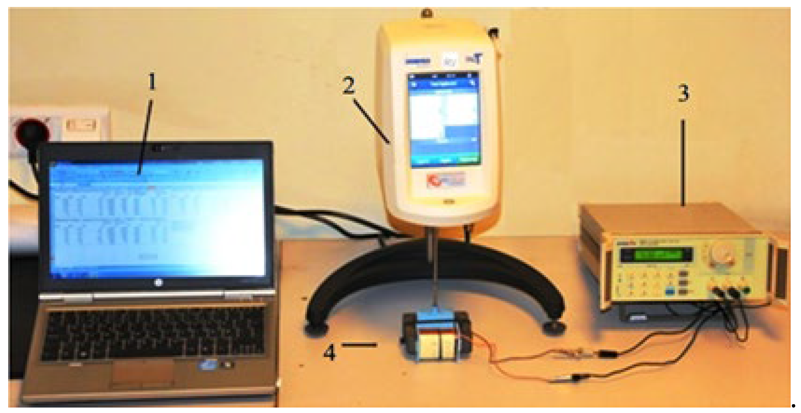
Figure 2.
View of the station used for testing the rheological properties of the MR fluid: 1 – PC, 2 – rheometer, 3 – electric power supply, 4 – magnetic device.
Figure 2.
View of the station used for testing the rheological properties of the MR fluid: 1 – PC, 2 – rheometer, 3 – electric power supply, 4 – magnetic device.
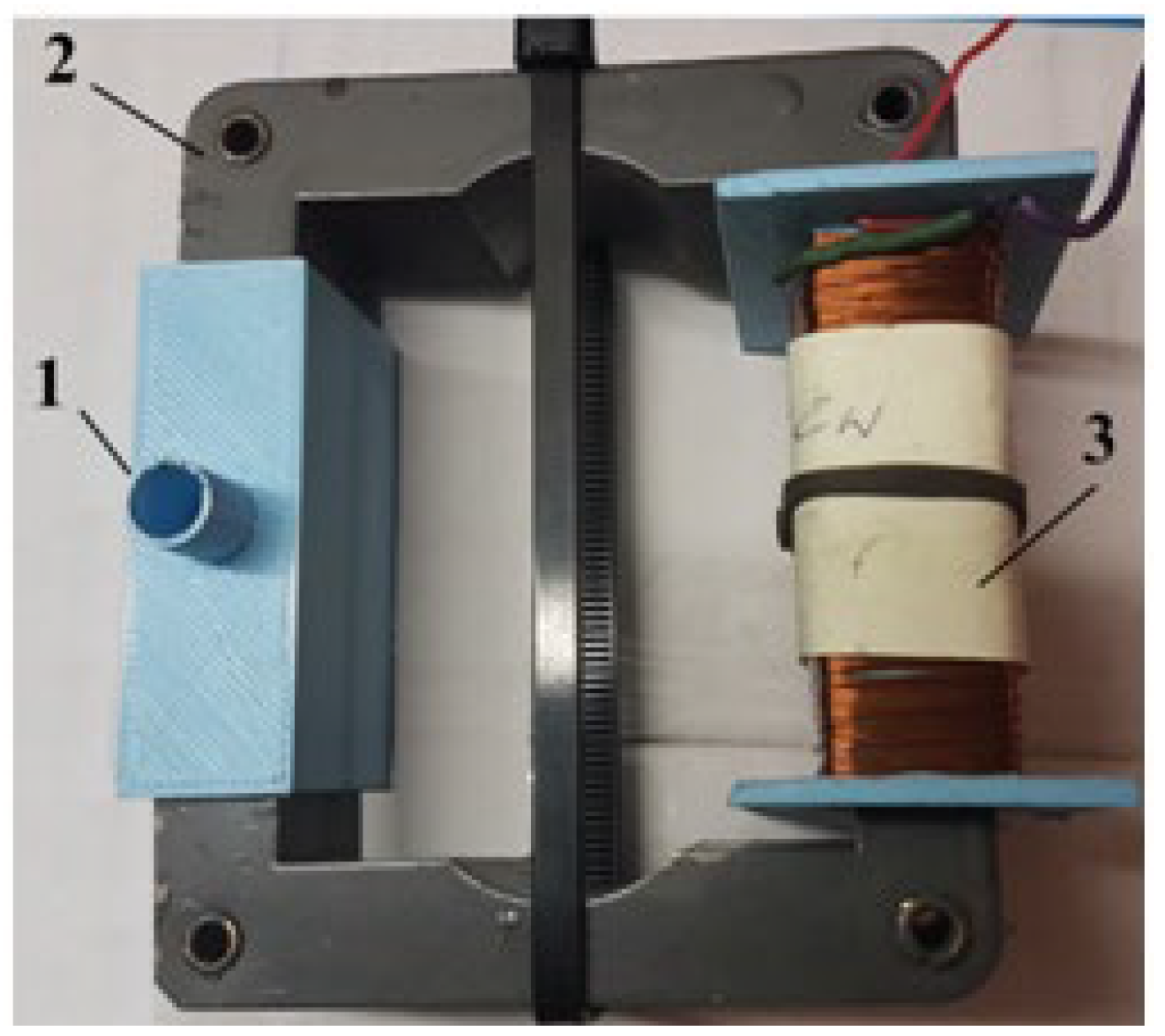
Figure 3.
Magnetic device used to test the MR fluid: 1 – beaker with MR fluid, 2 – electromagnet coil, 3 – magnetic circuit.
Figure 3.
Magnetic device used to test the MR fluid: 1 – beaker with MR fluid, 2 – electromagnet coil, 3 – magnetic circuit.
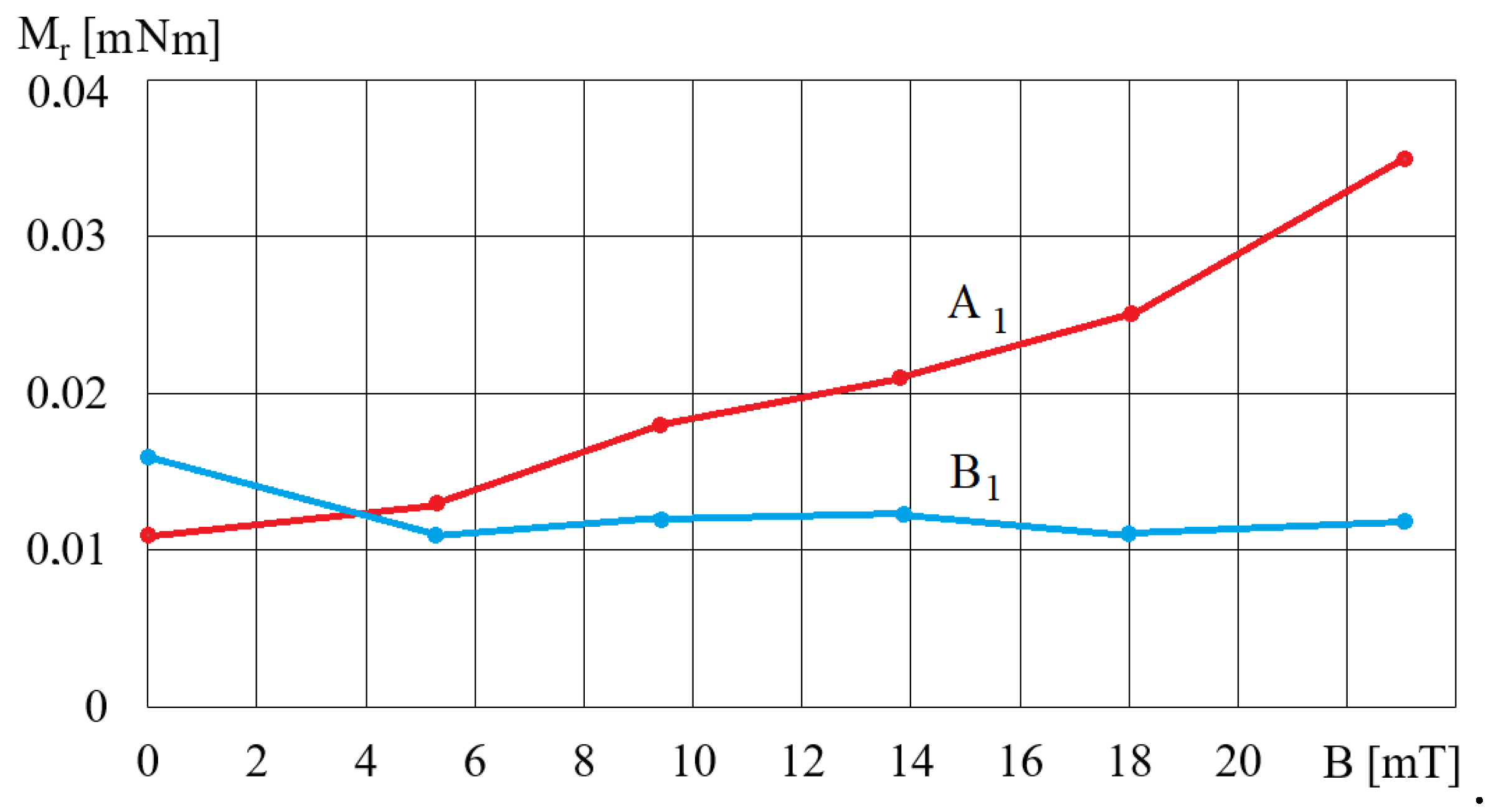
Figure 4.
The dependence of the torque Mr on magnetic induction B for fluids A1 and B1 and for ωr = 2 rad/s.
Figure 4.
The dependence of the torque Mr on magnetic induction B for fluids A1 and B1 and for ωr = 2 rad/s.
Figure 5.
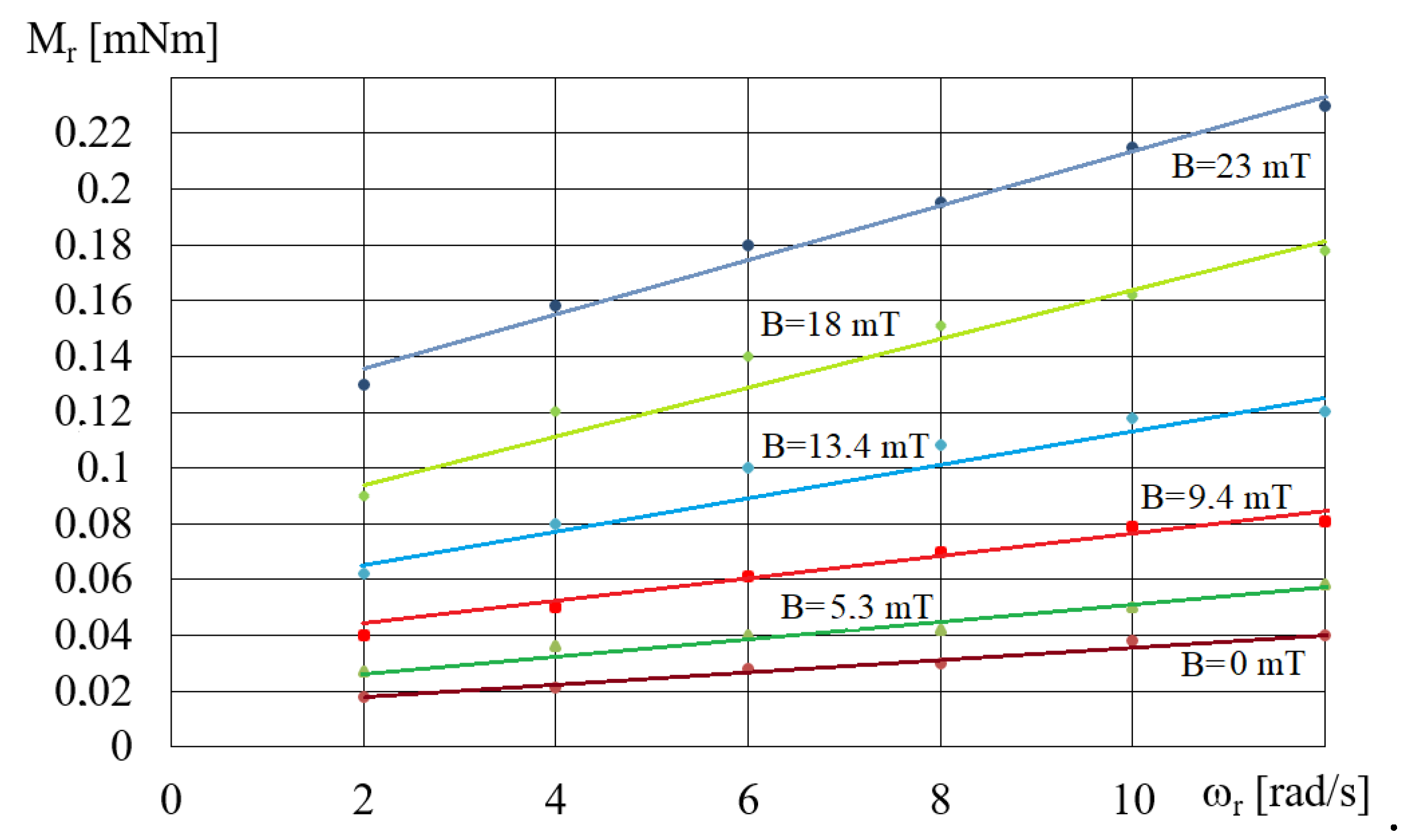
Dependences of the torque Mr on ωr for fluid A5 and different values of B.
Figure 5.
Dependences of the torque Mr on ωr for fluid A5 and different values of B.
Figure 6.
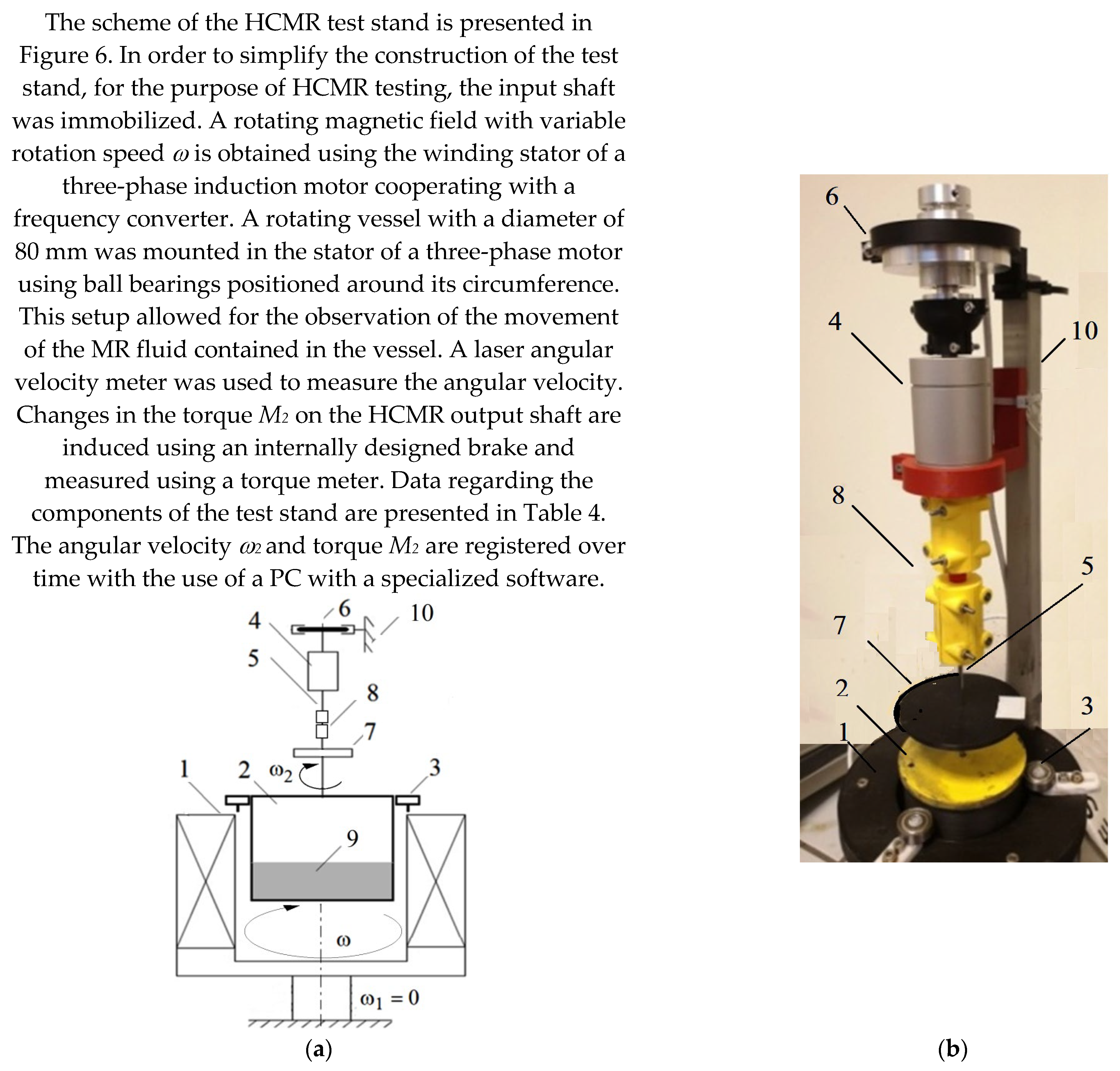
HCMR test stand: a – construction scheme: 1 – stator of a three-phase induction motor, 2 – beaker, 3 – beaker bearing, 4 – torque meter, 5 – output shaft, 6 – brake, 7 – rotational speed meter, 8 – clutch, 9 – MR fluid, 10–frame; b – view.
Figure 6.
HCMR test stand: a – construction scheme: 1 – stator of a three-phase induction motor, 2 – beaker, 3 – beaker bearing, 4 – torque meter, 5 – output shaft, 6 – brake, 7 – rotational speed meter, 8 – clutch, 9 – MR fluid, 10–frame; b – view.
Figure 7.
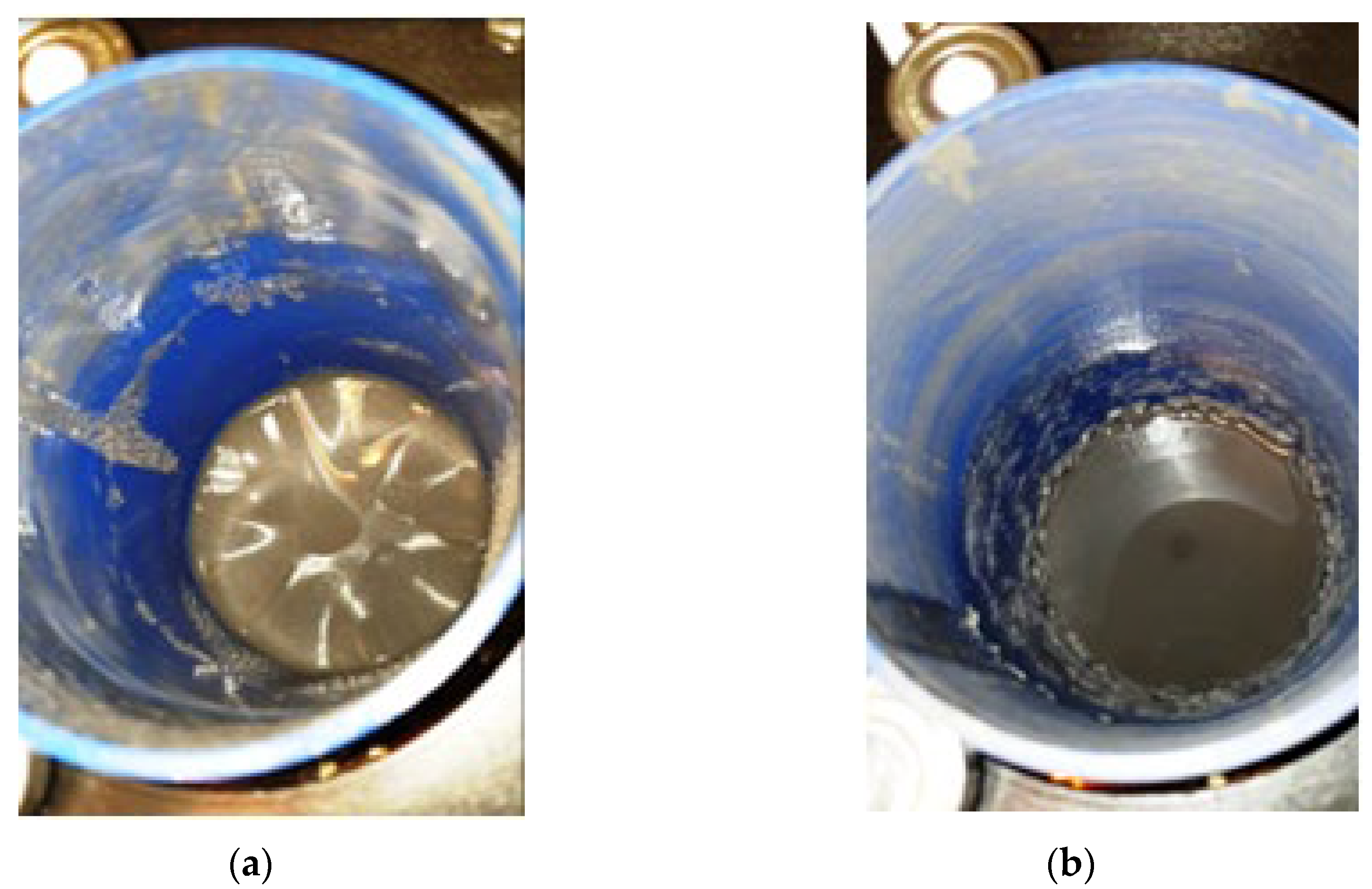
View of the B3 fluid surface at HCMR start-up for ω = 240 rad/s: a – wrinkles, b – ring of swirling fluid.
Figure 7.
View of the B3 fluid surface at HCMR start-up for ω = 240 rad/s: a – wrinkles, b – ring of swirling fluid.
Figure 8.
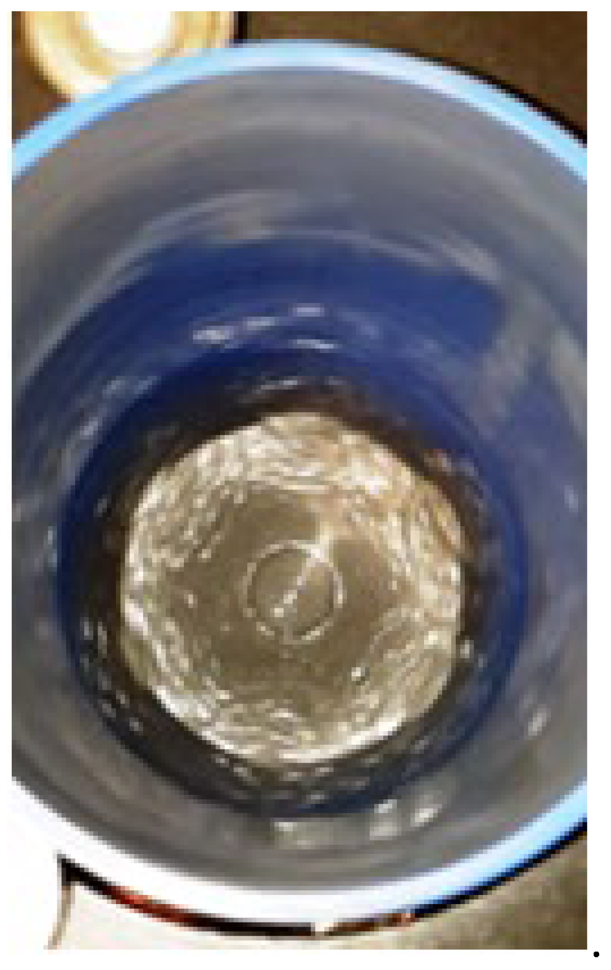
View of a hexagon formed by the rotation of the MR fluid for B3 fluid and ω = 240 rad/s.
Figure 8.
View of a hexagon formed by the rotation of the MR fluid for B3 fluid and ω = 240 rad/s.
Figure 9.
View of the potential vortex in fluid B2.
Figure 9.
View of the potential vortex in fluid B2.
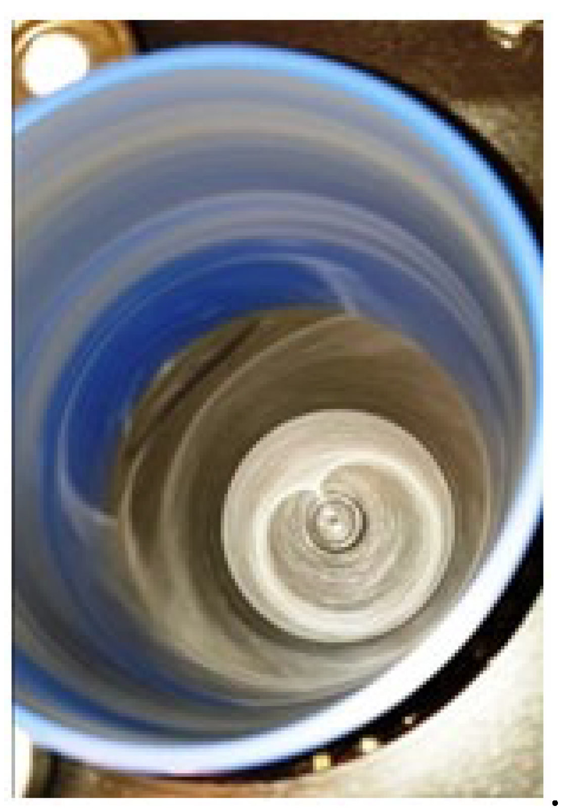
Figure 10.
View of the B2 fluid spread evenly on the beaker walls.
Figure 10.
View of the B2 fluid spread evenly on the beaker walls.
Figure 11.
Dependences of angular velocity ω2 on angular velocity ω for the fluid B5and fluid volume V = 75 cm3.
Figure 11.
Dependences of angular velocity ω2 on angular velocity ω for the fluid B5and fluid volume V = 75 cm3.
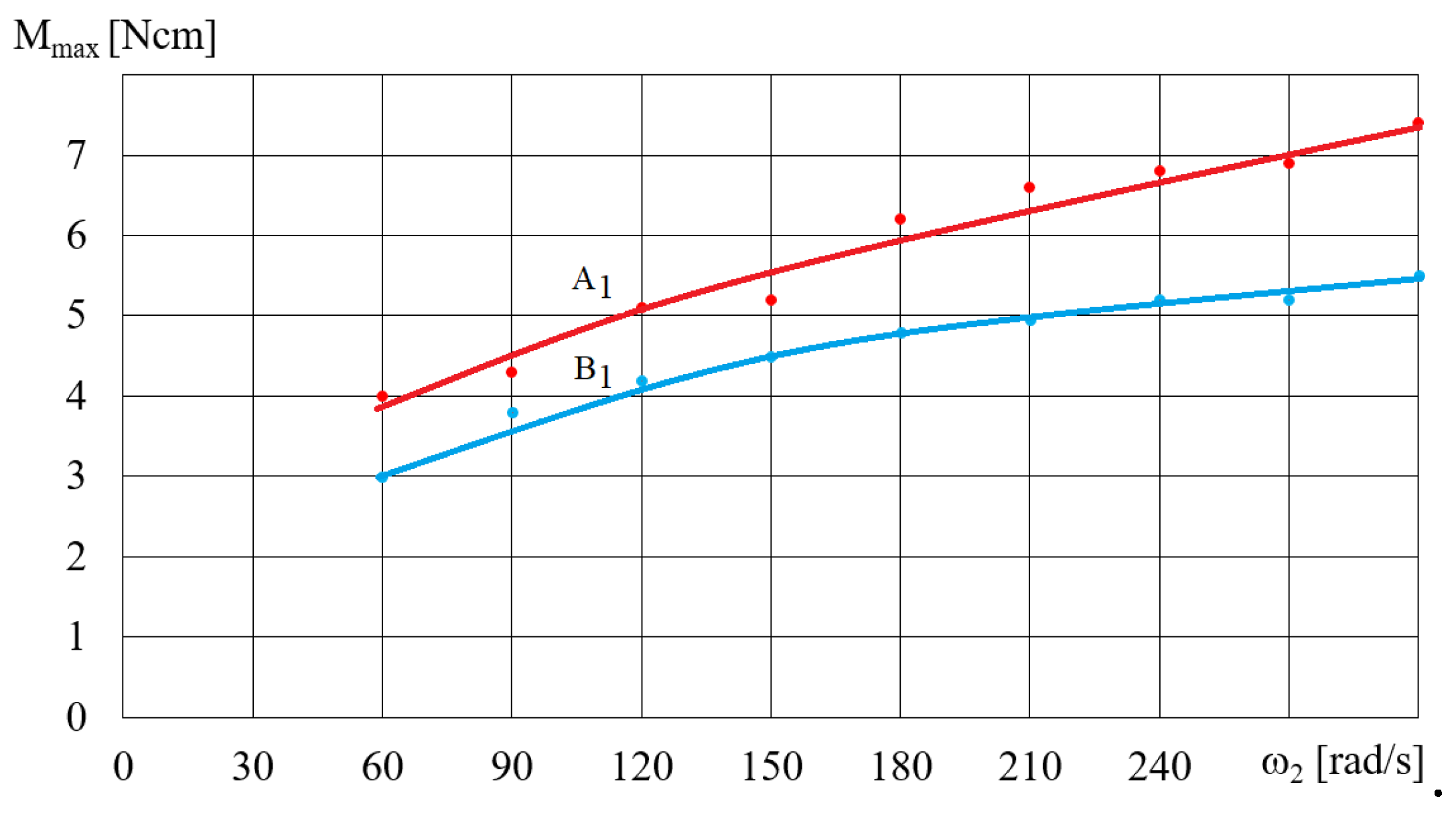
Figure 12.
Dependence of the torque M on the angular velocityω2 for fluids A1 and B1, ω = 300 rad/s, V = 75 cm3.
Figure 12.
Dependence of the torque M on the angular velocityω2 for fluids A1 and B1, ω = 300 rad/s, V = 75 cm3.
Figure 13.
Dependence of the torque M on the angular velocityω2 for fluid B for ω = 300 rad/s, V = 75 cm3.
Figure 13.
Dependence of the torque M on the angular velocityω2 for fluid B for ω = 300 rad/s, V = 75 cm3.
Figure 14.
Dependence of the torque M on the angular velocityω2for fluid B for ω = 300 rad/s, V = 75 cm3.
Figure 14.
Dependence of the torque M on the angular velocityω2for fluid B for ω = 300 rad/s, V = 75 cm3.
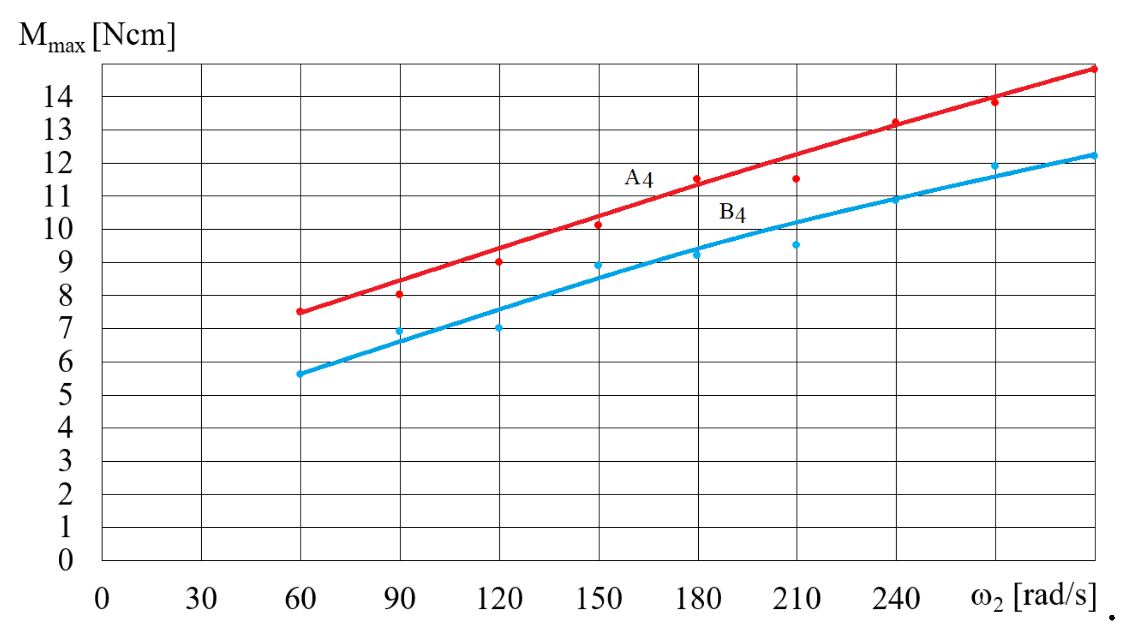
Figure 15.
Dependence of the torque Mmax on angular velocity ω for fluids A4 and B4, V = 75 cm3.
Figure 15.
Dependence of the torque Mmax on angular velocity ω for fluids A4 and B4, V = 75 cm3.
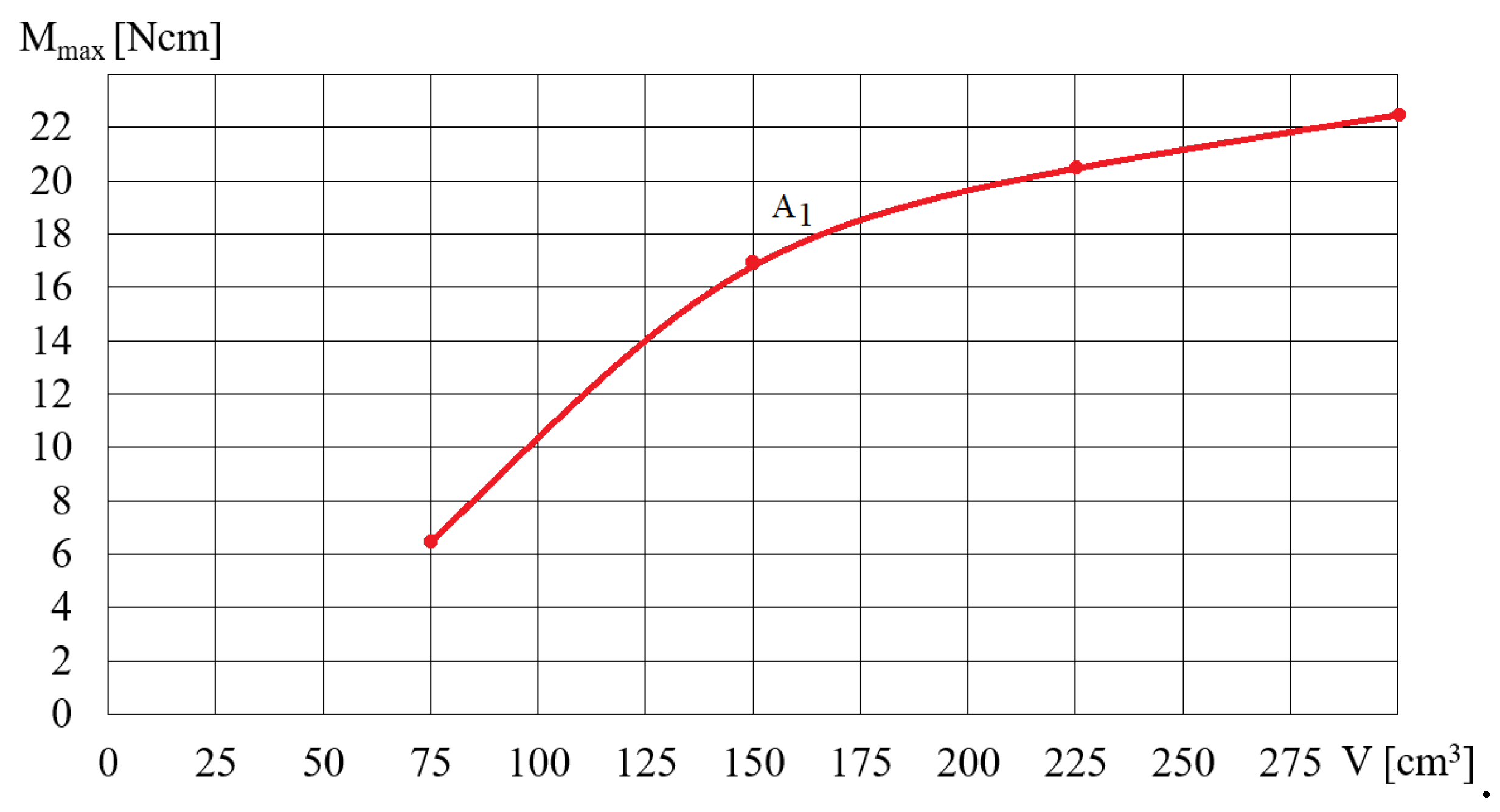
Figure 16.
Dependence of the torque Mmax on the volume V of the fluid A1for ω = 200 rad/s.
Figure 16.
Dependence of the torque Mmax on the volume V of the fluid A1for ω = 200 rad/s.
Figure 17.
Viscous-plastic model of Bingham’s fluid: F – force acting on particles, T – friction force, L – viscous force.
Figure 17.
Viscous-plastic model of Bingham’s fluid: F – force acting on particles, T – friction force, L – viscous force.
Figure 18.
Forces acting on the MR fluid and the beaker during HCMR operation: a – ω2 = ω; 1 – beaker wall, 2 – magnet, 3 –MR fluid pulled by the magnet, 4 – a ring of MR fluid; b – ω2<ω.
Figure 18.
Forces acting on the MR fluid and the beaker during HCMR operation: a – ω2 = ω; 1 – beaker wall, 2 – magnet, 3 –MR fluid pulled by the magnet, 4 – a ring of MR fluid; b – ω2<ω.
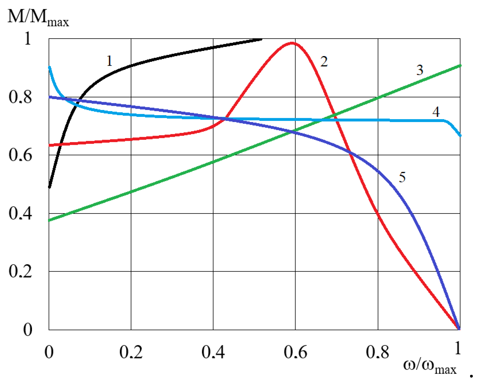
Figure 19.
Characteristics of clutches using the influence of a magnetic field: 1 – electromagnetic friction-type clutches, 2 – induction clutches, 3 –viscous clutches with MR fluid, 4 –magnetic particle clutches, 5 – eddy current clutches.
Figure 19.
Characteristics of clutches using the influence of a magnetic field: 1 – electromagnetic friction-type clutches, 2 – induction clutches, 3 –viscous clutches with MR fluid, 4 –magnetic particle clutches, 5 – eddy current clutches.
Table 1.
Names and composition of the in-house manufactured MR fluids.
Table 1.
Names and composition of the in-house manufactured MR fluids.
| Name |
Fe particles’ size |
Base fluid |
| A |
From 3.5 μm to 6.5μm |
Silicon oil OL.111 |
| B |
From 100 μm to 150μm |
Silicon oil OL.111 |
Table 2.
The weight concentration ratio in the tested MR fluids.
Table 2.
The weight concentration ratio in the tested MR fluids.
| Symbol |
Density [g/cm3] |
Weight concentration ratio of solid particles ϕ [%] |
| 1 |
1.69 |
0.50 |
| 2 |
2.01 |
0.60 |
| 3 |
2.30 |
0.67 |
| 4 |
2.56 |
0.72 |
| 5 |
2.79 |
0.75 |
Table 3.
Dimensions of the magnetic device for the rheometer Brookfield DV2T.
Table 3.
Dimensions of the magnetic device for the rheometer Brookfield DV2T.
| Parameter |
Value |
| Spindle radius RV-07 (7) |
2.1 mm |
| Internal radius of the tank opening |
3.25 mm |
| Maximum spindle immersion depth |
35 mm |
| Length of the electromagnet core |
276 mm |
| Cross-section of the electromagnet core |
24 mm x 12 mm |
| Wire diameter and number of turns of the electromagnet coil |
0.25 mm x 850 |
| Spindle angular velocity range |
2 rad/s–10 rad/s |
| MR fluid temperature during testing |
25 o C |
Table 4.
Data regarding the components of the test stand.
Table 4.
Data regarding the components of the test stand.
| Component |
Designation |
| Frequency converter |
LG SV008iC5-1F |
| Engine stator |
230 V 0.75 kW |
| Brake |
MH1 |
| Temperature sensor |
NTC 215 |
| Angular velocity meter |
Measure Me MT522 |
| Torque gauge |
MT1 |
