1. Introduction
Gravitational waves are material waves that are ubiquitous in the Universe. The detection and research on gravitational waves would elucidate the mystery of dark matter (energy), which accounts for more than 95% of the mass, thus providing a complete picture of the Universe [
1]. On February 11, 2016, the Laser Interference Gravitational-Wave Observatory (LIGO) [
2] announced the direct observation of gravitational wave signals, opening a new era of physics [
3,
4]. Compared with ground-based gravitational wave detection, space-based detection can address the limitations of ground-based noise [
5,
6,
7] and interferometer scale, enabling the detection of gravitational waves in the medium and low-frequency bands [
8,
9,
10]. The success of Laser Interferometer Space Antenna Pathfinder(LPF) validates the feasibility of gravitational wave detection in space [
11,
12,
13,
14]. The subsequent detection plan, the Laser Interferometer Space Antenna(LISA) project, is currently under pre-research and simulation, with a targeted launch date around 2035 [
15].
In 2016, the Chinese Academy of Sciences proposed the Taiji Space Gravitational Wave Detection Program [
16,
17]. The program aims to use Taiji spacecrafts to form a formation of three spacecrafts in Earth-like orbits around the Sun, describing an equilateral triangle with a side length of 3 million km [
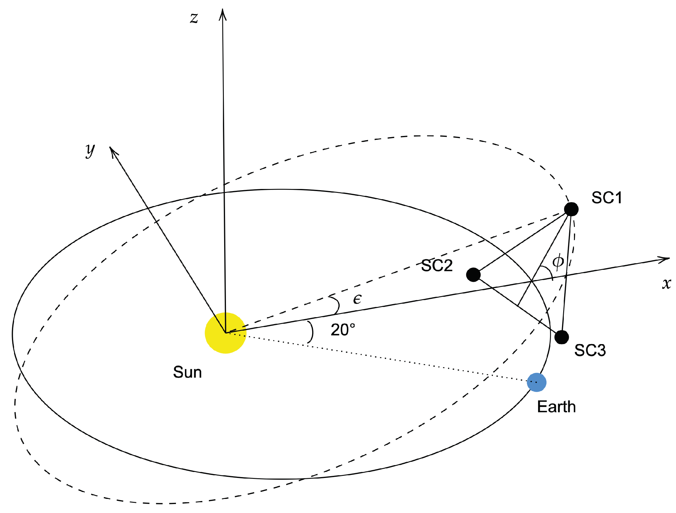
18]. These three spacecrafts are distributed approximately 20° in front of (or behind) the earth, and the angle between the spacecraft formation plane and the ecliptic plane is 60° [
19,
20]. In space-based gravitational wave detection, the length of the laser interference arm changes with time [
21]. The instability of the laser frequency is one of the main sources of noise. Time-delay interferometry (TDI) technology [
22,
23] is proposed to reduce this measurement noise. The implementation of TDI requires precise spacecraft absolute range measurement and real-time communication. Thus, the stability of spacecraft orbits should be investigated. Spacecrafts operate in a complicated gravitational environment. The orbit calculations must consider a variety of disturbances, such as planetary gravity, planetary tidal force, lunar gravity, solar light pressure, and post-Newtonian effects [
24]. Planetary gravity is one of the dominant factors, especially the gravities of Earth, Venus, and Jupiter, which has a significant impact on orbital stability [
25,
26].
This study calculates the armlength, armlength variation rate, and breathing angle variation of the Taiji constellation under planetary gravitational perturbations. Employing ephemeris DE440 and based on the Keplerian orbit of Taiji, these variations under the influence of the gravities of Venus, Earth, and Jupiter were evaluated. Our analysis showed that the variations in the heliocentric formation configuration are primarily influenced by Earth’s gravitational perturbations. Numerical simulations based on ephemeris DE440 show that the contribution of the earth’s gravity to the relative acceleration between spacecrafts is approximately . Considering 00:00:00 on October 23, 2032 as the initial orbiting moment as an example, when the earth’s gravitational perturbation is determined, within six years the maximum amplitude of the relative variation in the armlength is , maximum amplitude of the relative variation in breathing angle is , and maximum amplitude of the relative variation in the armlength variation rates is , compared with the unperturbed Keplerian configuration. By adding the gravitational perturbations of Venus and Jupiter, the armlength and relative velocity are reduced by and , respectively, compared with when only the Earth’s gravitational perturbation is considered. Results showed that the maximum amplitude of Taiji constellation armlengths, armlength variation rate, and breathing angles varied with orbital entry moments. The maximum amplitude of the inter-spacecraft armlength change rate is the smallest when the initial orbital moment occurs in July. When the orbital entry moment is 00:00:00 on July 1, 2032, the maximum amplitude of the reduced armlengths is approximately , the maximum amplitude of the reduced breathing angles is approximately 1.6°, and the maximum armlength variation rate is approximately within six years.
We show that by using different ephemeris for the calculations, the constellation armlengths deviate in the order of , constellation armlength variation rate deviates in the order of , and relative accelerations deviate in the order of within six years. The differences between ephemeris DE440 and DE430 are smaller than those between DE440 and DE421.
The remainder of the paper is presented as follows: In Sec. 2, we derive the expressions for the positions and velocities of spacecrafts in the Keplerian configuration. The armlengths, armlength variation rate, inter-spacecraft relative acceleration, and breathing angles are determined. In Sec. 3, we discuss the effect of planetary gravitational perturbations on the heliocentric formation configuration and the effect of different entering orbit moments. In Sec. 4, we compare the calculation results using different ephemeris. In Sec. 5, we present the conclusions.
2. The Keplerian Orbital Configuration of Taiji
2.1. The Keplerian Orbit
Several orbital have been designed for the Taiji heliocentric formation configuration [
9,
10,
27]. We adopted a Keplerian orbital configuration model proposed in Ref. [
28], as part of the Taiji program preview.
Figure 1.
Taiji configuration and orbit.
Figure 1.
Taiji configuration and orbit.
In the Keplerian configuration, the heliocentric reference system ECLIPJ2000 is chosen, the argument of periapsis is denoted as
, and the longitude of the ascending node is denoted as
. When
, spacecraft 1 (SC1) is at the highest point of the orbit and is located in the XZ plane. This can be associated with the determination of
and
of SC1 as 270° [
29]. As the three orbits have rotational symmetry about the Z-axis with a rotation angle of 120°, the
values of spacecraft 2 (SC2) and spacecraft 3 (SC3) are the same as that of SC1 with
. SC2 has
, and SC3 has
. Notably, the orbital semi-major axis of the three spacecrafts is
a, eccentricity is
e, and inclination is
. The spacecraft position vectors
and the spacecraft velocity vectors
can be expressed as follows:
and
where
is the eccentric anomaly, which can be obtained from the Kepler equation
where
is the average angular velocity of the spacecraft.
In the Taiji program, the half-length axis is
, the orbital eccentricity is
, and the orbital inclination
is given by Eq. (
4) [
28],
where
is the angle between the plane of spacecraft formation and ecliptic plane, and
is a small parameter for the expansion,
. The spacecraft position
and velocity
varied with time
t, as expressed in the above equation.
2.2. Configuration Parameter
The armlength
, armlength variation rate
, relative acceleration between the spacecrafts
, and breathing angle
of the constellation are as follows:
where
is the angle between vector
and vector
and
.
By defining the reduced armlength as
and the reduced breathing angle as
, we obtain the variation of Taiji constellation reduced armlengths, armlength variation rate, and reduced breathing angles within six years, as shown in
Figure 2,
Figure 3.
In the Keplerian orbital configuration, the reduced armlength amplitude is approximately , rate of the armlength amplitude variation is , breathing angle amplitude is , and relative acceleration amplitude is approximately .
3. Taiji Heliocentric Formation Configuration
3.1. Influence of the Gravitational Field of the Solar System Stars
As we aim to evaluate the influence of the gravitational fields of celestial bodies on the configuration of spacecraft formation, we consider only the Newtonian gravitational forces of the Sun and other 9 bodies, Mercury, Venus, Earth, Mars, Jupiter, Saturn, Uranus, Neptune, and the Moon, in the solar system (
). The motion equation of the spacecraft in heliocentric ECLIPJ2000 can be expressed as
where
is the spacecraft position vector,
,
,
s denotes the Sun, and
G is the gravitational constant.
For this specific formation configuration, the initial mission time is 00:00:00 on October 27, 2032 (heliocentric ecliptic coordinate system), and the initial position and velocity are presented in
Table 1.
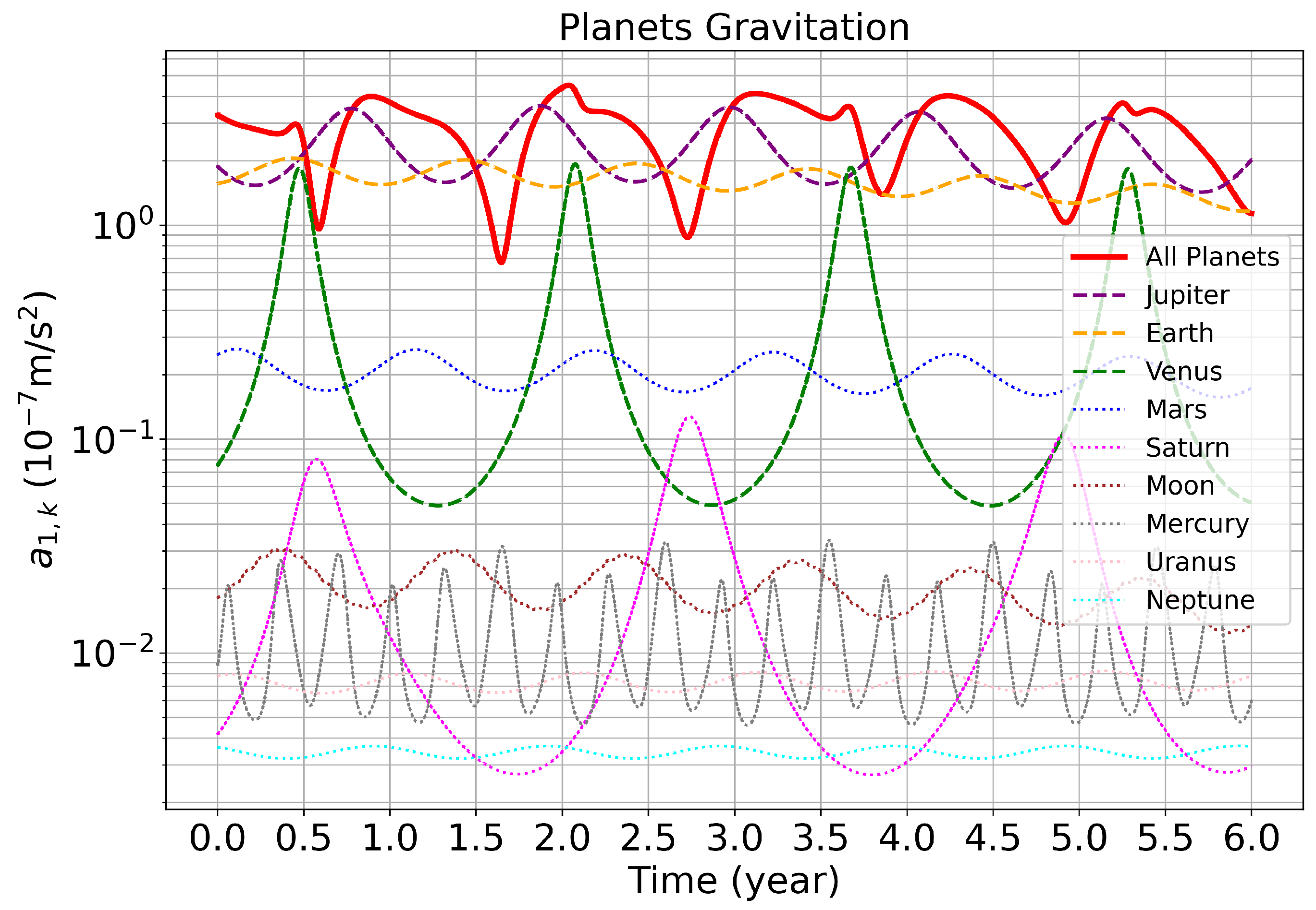
The acceleration of each planet toward SC1 is
We obtain the planet position from the DE440 ephemeris, substitute it into the Eq. (
6), and obtain the result as shown in
Figure 4.
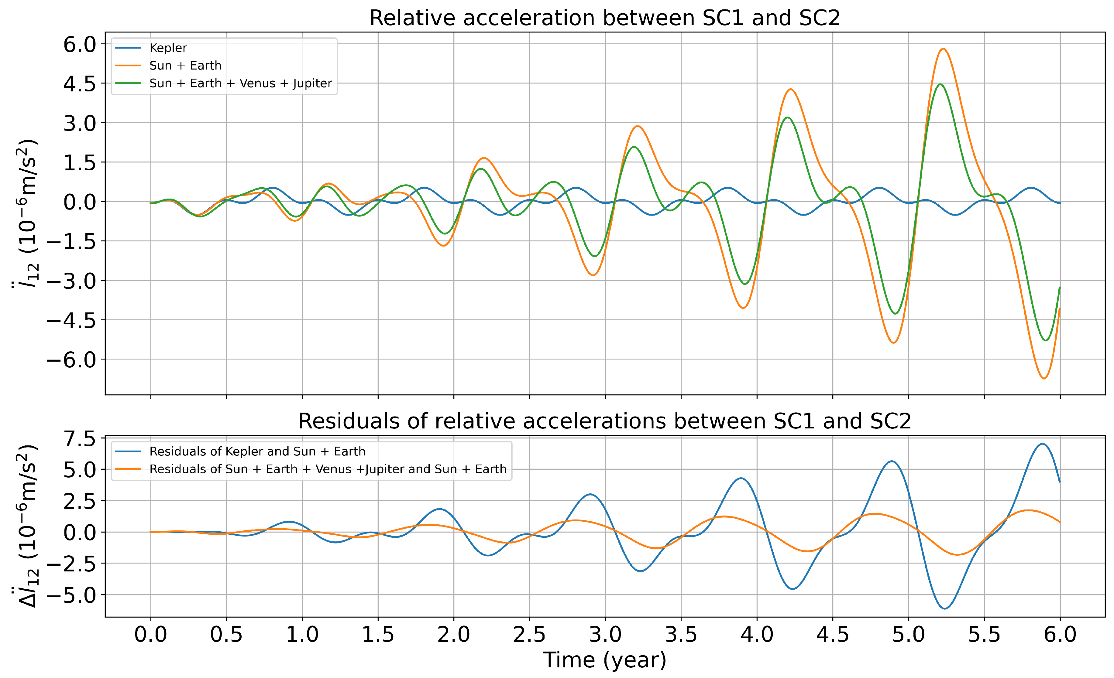
It shows that the gravitational attractions exerted by the Earth, Venus, and Jupiter on spacecrafts are greater than those of other celestial bodies in the solar system and may have a greater variation on the spacecraft formation configuration. The contribution of the gravitational disturbances of the Earth, Venus, and Jupiter to the relative acceleration between spacecrafts obtained by numerical simulation is shown in
Figure 5.
As shown in
Figure 4 and
Figure 5, the gravitational perturbations of Venus, Earth, and Jupiter cause a variation in the spacecraft orbit. The maximum variation is of
. The Earth’s gravitational perturbation has the greatest variation in the heliocentric formation configuration of
. Subsequently, we will examine variations in spacecraft formation configuration parameters perturbed solely by Earth’s gravity.
3.2. Influence of the Gravitational Perturbation of the Earth
Considering the gravitational perturbation of the earth, the motion equation of the spacecraft can be expressed as
Substituting the initial conditions in Table.
Table 1 into Eq. (
8), the spacecraft position vector
can be obtained. Substituting
into Eq. (
5) and comparing it with the Keplerian orbits, the result is shown in
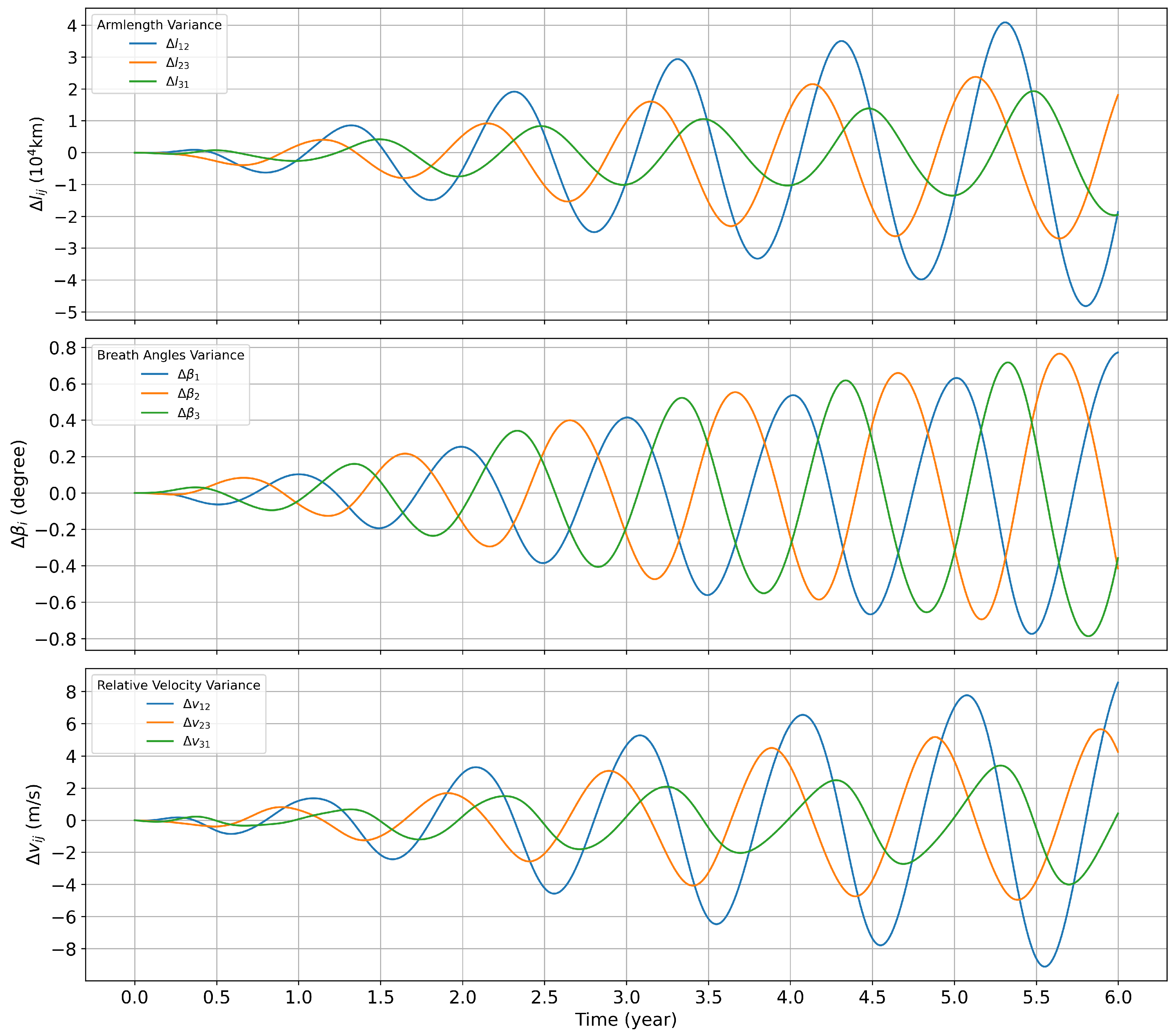
Figure 6.
Considering the Earth’s gravitational perturbations, the orbits of spacecrafts in the heliocentric formation deviate from the Kepler orbit. This deviation changes the spacecraft formation configuration and increases the magnitude of the configuration parameters. Specifically, the maximum amplitude of the relative change in armlength between spacecrafts is , maximum amplitude of the relative change in relative velocity between spacecrafts is , and maximum relative change in the breathing angle is within six years.
3.3. Influence of the gravitational perturbation of Venus and Jupiter
To obtain accurate configuration parameter variations, the influence of the gravities of Venus and Jupiter on the spacecraft formation configuration must be considered. Choosing
to represent Venus, Earth, and Jupiter in the equation repectiveliy, for a single spacecraft in the heliocentric formation configuration, respectively, the following acceleration can be obtained.
Substituting
into Eq. (
5) and comparing it with the perturbation of the spacecraft formation configuration parameters caused exclusively by the Earth’s gravity, the results are shown in
Figure 7.
As shown in
Figure 7, in addition to the gravity perturbation of the Earth, the configuration parameters will change when the gravity perturbation from Venus and Jupiter is included. The maximum relative variations in inter-spacecraft armlength and relative velocity are
and
, respectively, within six years. The maximum relative variation in breathing angle is approximately
.
However, the relative magnitude of the changes does not accurately reflect the influence of the perturbations of Venus and Jupiter.
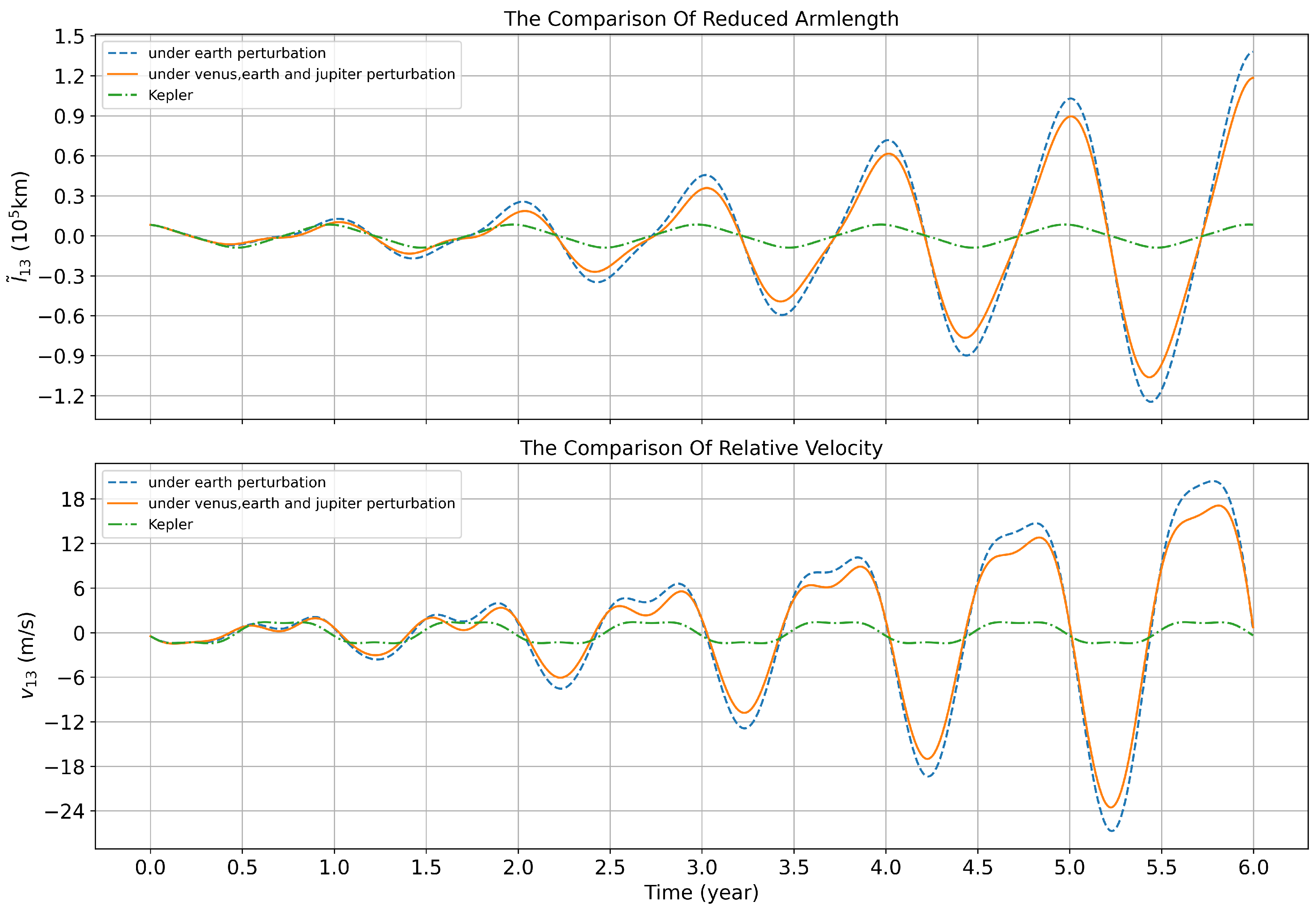
Figure 8 compares the changes in spacecraft formation configuration parameters in the three cases: the unperturbed Keplerian configuration, adding only the gravitational perturbation of the Earth, and adding the perturbations of Venus and Jupiter.
As shown in
Figure 8, when considering the gravitational disturbances of Venus and Jupiter in addition to the gravitational disturbances of the Earth, the reduced armlengths and armlength variation rate decrease by
and
, respectively.
The findings indicate that when the orbit entry time is set to 00:00:00 on October 27, 2032, the Earth’s gravity amplifies the variations in the constellation armlength, change rate, and breathing angle. However, the gravitational perturbations of Venus and Jupiter reduce the magnitude of the constellation configuration parameters.
3.4. Orbital Entry Moment
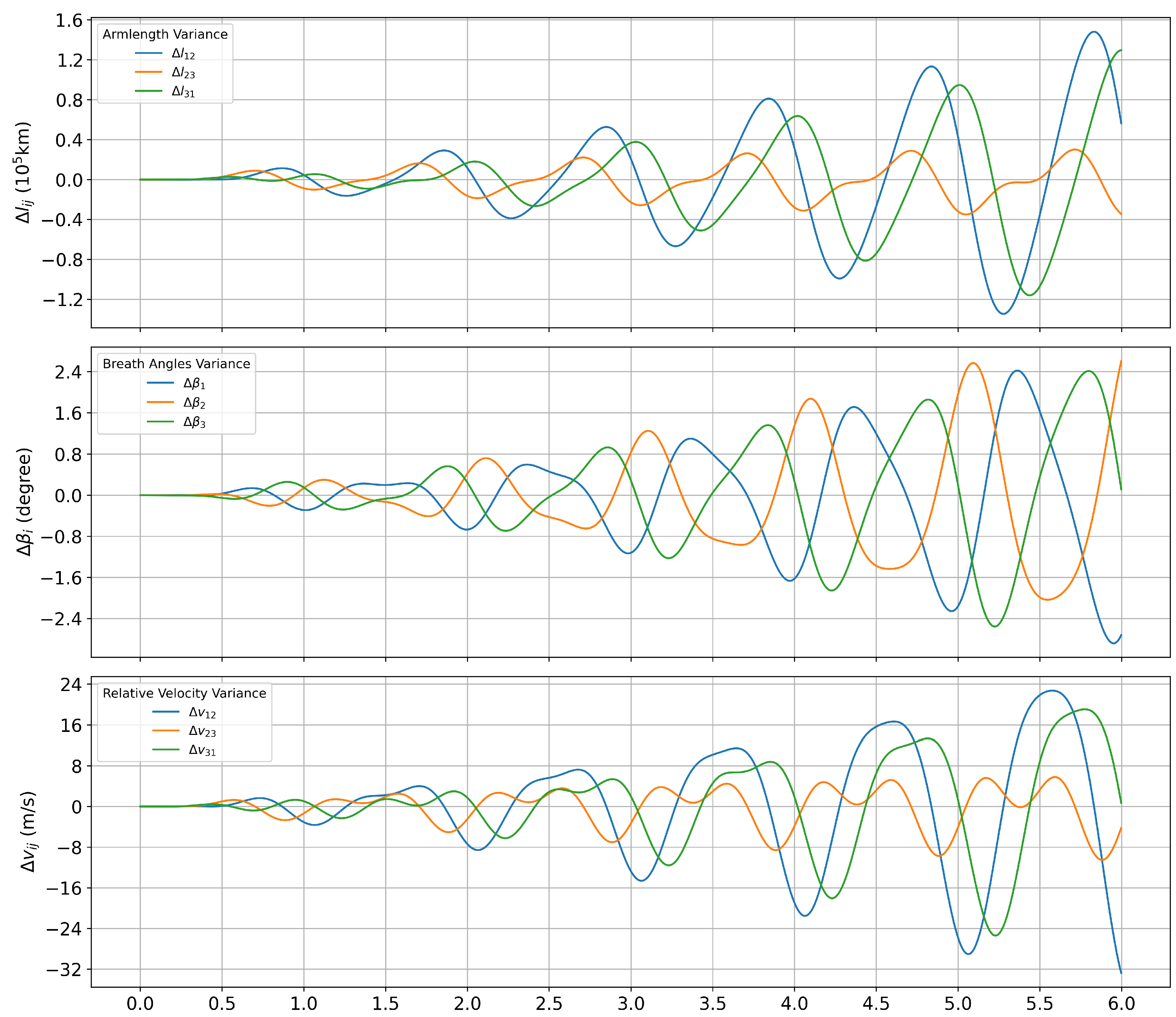
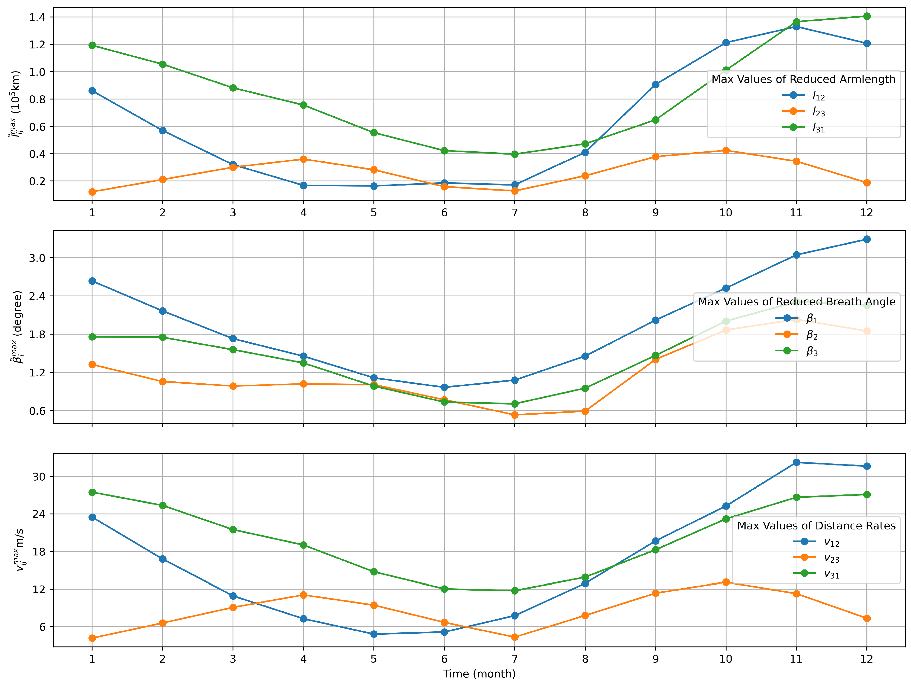
The orbital entry moment is an optimization variation that affects the orbit design, and the different initial orbiting moments change the initial position and velocity of the spacecraft. In this section, different initial positions and velocities are obtained by changing the initial orbital entry moment of the formation. Further, the changes in configuration parameters at different orbital entry moments are analyzed. The specified orbiting time is set as 00:00:00 on the first day of each month in 2032. The simulation assesses the variations in the armlengths, breathing angles, and armlength variation rates over six years following the different orbiting times, which are shown in
Figure 9.
Notably, variations in the maximum amplitudes of the configuration parameters are observed at different orbital moments. Specifically, in July, the maximum amplitudes of the armlength and relative velocity between the spacecrafts are the smallest over one year. Consequently, selecting July as the moment of orbit entry is conducive to extending the mission duration.
Through sensitivity analysis of the initial orbital entry moment of the heliocentric formation, the orbital moment chosen was 00:00:00 on July 1, 2032. The initial positions and velocities of the spacecraft are presented in
Table 2.
By substituting the parameters in Table.
Table 2 into Eq. (
9), the position vector
of the spacecraft can be determined. The vector in Eq. (
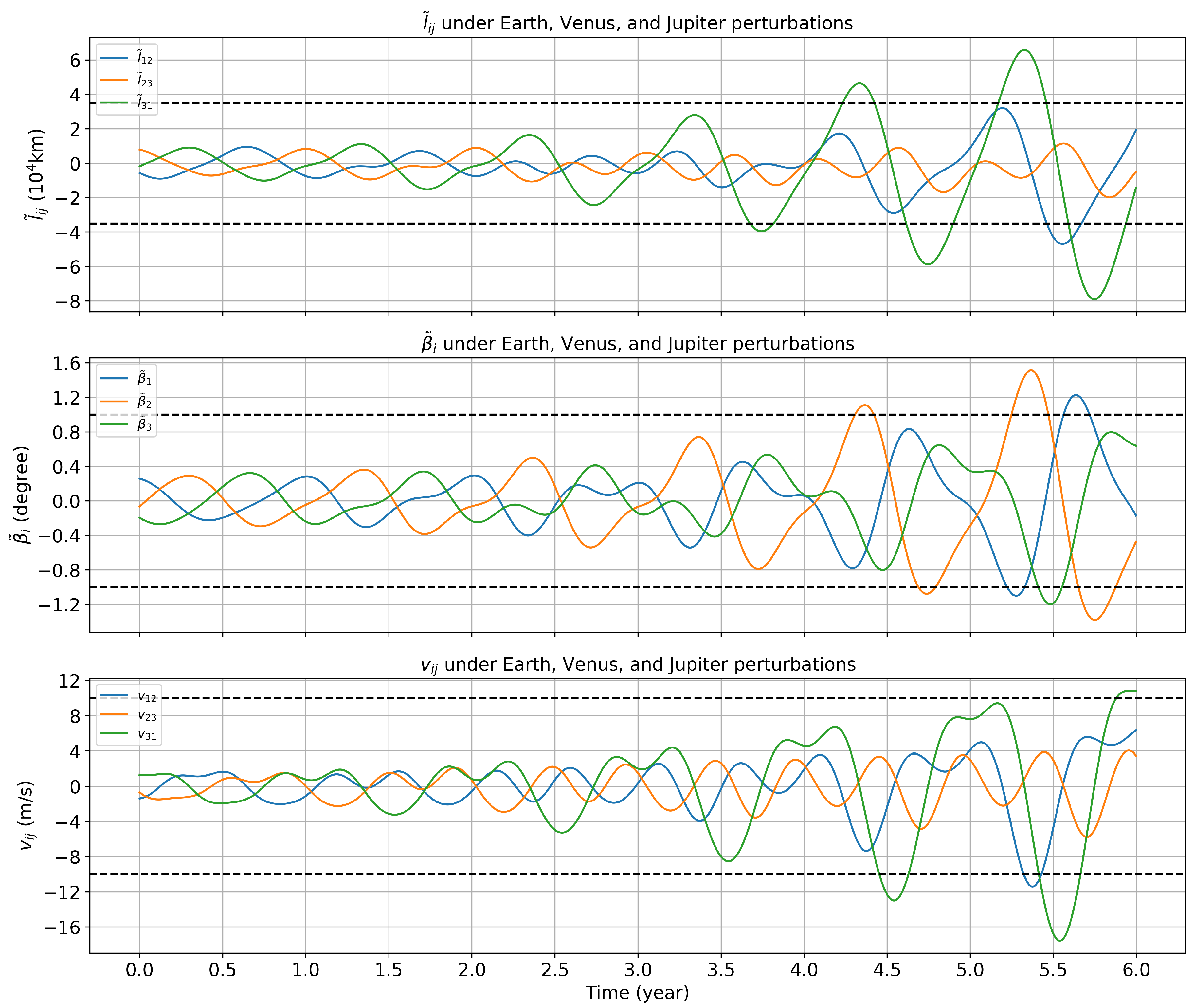
1) is used to calculate the variation in spacecraft formation configuration parameters, as shown in
Figure 10.
The findings indicate that selecting the orbital entry moment as 00:00:00 on July 1,2032, while accounting for the gravitational perturbation of Venus, Earth, and Jupiter, results in a maximum amplitude of approximately in the reduced armlengths, maximum armlength variation rates of , and maximum amplitude of approximately in the reduced breathing angles over six years.
4. Simulation with Different Ephemeris
The accuracy of the numerical simulation results depends on that of the planetary position data. Differences in planetary orbital positions may occur in various ephemeris due to variations in the chosen fitting data and the integration method used[
30]. These deviations can affect the numerical simulation of spacecraft configuration parameters. Therefore, the biases in numerical simulations caused by different ephemeris as input should be extensively investigated.
We obtained planetary position data from the ephemeris DE440, DE430 and DE421[
31,
32,
33]. In the heliocentric equatorial coordinate system J2000, the maximum disparities in the coordinates of Venus, Earth, and Jupiter relative to the solar center of mass are presented in Table.
Table 3 across various ephemeris.
Comparatively, the maximum coordinates of the ephemeris of the three planets differ significantly: Venus and Earth differ at the 100-m level, while Jupiter differs at the 10-km level.
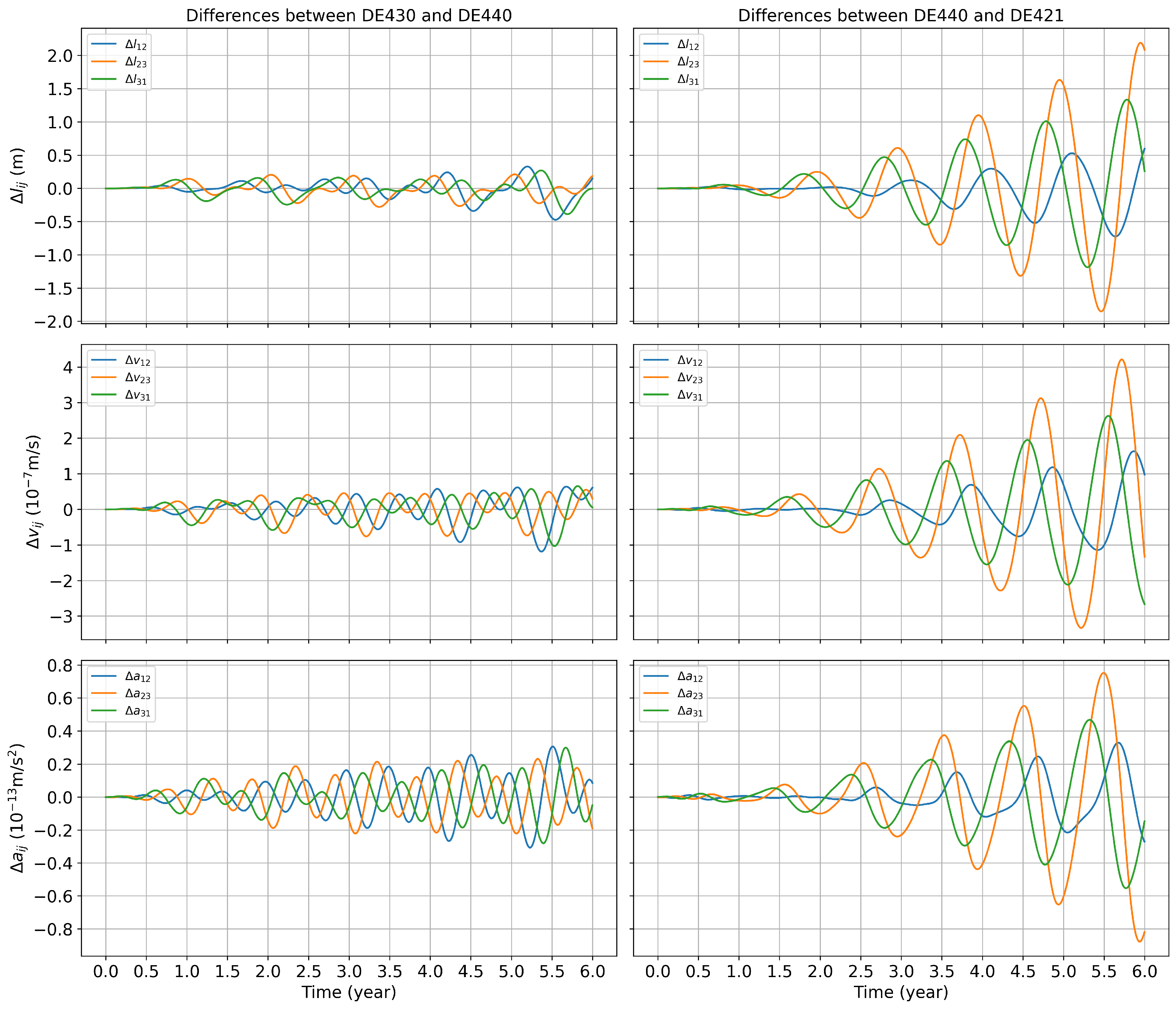
Discrepancies in the planetary coordinates between ephemeris can cause variations in the forces acting on the spacecrafts. Consequently, these variations may alter the relative acceleration between the spacecrafts, thereby affecting the overall configuration of the formation. Three ephemerises, DE421, DE430 and DE440, were used for numerical simulations with an initial entry time of 00:00:00 on July 1, 2032.
Figure 11 shows the difference in spacecraft armlengths, armlength variation rates, and relative accelerations within six years.
Figure 11, shows differences in the spacecraft configuration parameters obtained via numerical simulation using different ephemeris.
Specifically, the variation between DE440 and DE430 is relatively small, with a difference of approximately in armlength over six years, in armlength variation rates, and in relative acceleration. Conversely, the variation between DE421 and DE440 is significant, with a difference of approximately in armlength, in armlength variation rates, and in relative acceleration within six years.
Notably, the variable period of the difference in spacecraft structural parameters obtained via the numerical simulation of different ephemeris is approximately one year, and the frequency is relatively low. It is relatively small compared to the change in the gravitational wave frequency band targeted by the Taiji project.
5. Conclusion
Using the DE series of ephemerises, we investigated the influence of celestial gravitational perturbations on the heliocentric formation configuration. Specifically, variations in the major planets in the solar system on the orbital stability of the Taiji space gravitational wave detector were investigated. Ephemeris DE440 was used to interpolate the planetary orbital position during the mission, and the high-order Runge–Kutta numerical integration method was used to calculate planetary gravity [
34]. The trajectory of each spacecraft in the heliocentric formation configuration under the influence of perturbation was numerically simulated.
Results showed that the gravitational acceleration affecting an individual spacecraft within a spacecraft formation due to planetary gravity is approximately . The relative acceleration between spacecrafts due to planetary gravity is approximately . The difference in the heliocentric formation configuration is mainly affected by the gravity of the earth. Considering 00:00:00 on October 27, 2032 as the initial orbit entry moment as an example, when only the Earth’s gravitational perturbation is considered, the maximum amplitude of the relative change in the armlength within six years was , maximum amplitude of the relative change in breathing angle was , and maximum amplitude of the relative change in armlength variation rates was .
Further, we discuss the spacecraft formation configuration changes with the addition of gravitational perturbations from Venus and Jupiter. The results showed that compared with the case where only the Earth’s gravitational perturbation was considered, after the gravitational perturbations of Venus and Jupiter were added, within six years the maximum amplitude of the relative change in armlength was approximately , maximum amplitude of the breathing angle was approximately , and maximum amplitude of the relative change in armlength variation rates was . After adding the gravitational perturbations of Venus and Jupiter, the armlength and relative velocity were reduced by and , respectively, compared with when only the earth’s gravitational perturbation was considered.
Variations in the maximum amplitudes of the formation configuration parameters were observed when entering orbit at different times. The smallest increase in armlength variation rates between the spacecrafts occurred when the initial orbiting time was in July. Consequently, selecting July as the initial orbital insertion time extends the experiment duration. By considering 00:00:00 on July 1, 2032 as the initial orbit entry moment, under the gravitational perturbations of Venus, Earth, and Jupiter, using DE440 ephemeris, the maximum amplitude of the reduced armlength was , maximum amplitude of the reduced breathing angle was , and maximum armlength variation rates was within six years.
Ephemeris data were used to perform numerical simulations. By comparison, the maximum disparity in the orbital positions of Venus and Jupiter was and , respectively. The armlength deviation over the six-year simulation period was approximately . The deviation in armlength variation rates was in the order of , and the deviation in relative accelerations was approximately . The differences between ephemeris DE440 and DE430 are smaller than those between DE440 and DE421. Nonetheless, the impact of discrepancies in high-frequency bands induced by factors such as planetary rotation remains unexplored and warrants consideration in future studies.
Author Contributions
Conceptualization, Y.Y.Z., G.L. and B.W.; methodology, Y.Y.Z., G.L. and B.W.; software, Y.Y.Z., G.L. and B.W.; validation, Y.Y.Z., G.L. and B.W.; formal analysis, Y.Y.Z., G.L. and B.W.; investigation, Y.Y.Z., G.L. and B.W.; resources, Y.Y.Z., G.L. and B.W.; data curation, Y.Y.Z. and B.W.; writing—original draft preparation, Y.Y.Z.; writing—review and editing, G.L.; visualization, B.W.; supervision, G.L.; project administration, Y.Y.Z., G.L. and B.W.; funding acquisition, G.L. All authors have read and agreed to the published version of the manuscript.
Funding
This research was funded by the National Natural Science Foundation of China (NSFC) under Grant No. 12247160.
Data Availability Statement
Data is contained within the article or supplementary material.
Conflicts of Interest
The authors declare no conflicts of interest. The funders had no role in the design of the study; in the collection, analyses, or interpretation of data; in the writing of the manuscript; or in the decision to publish the results.
Abbreviations
The following abbreviations are used in this manuscript:
| MDPI |
Multidisciplinary Digital Publishing Institute |
| DOAJ |
Directory of open access journals |
| LIGO |
Laser Interference Gravitational-Wave Observatory |
| LISA |
Laser Interferometer Space Antenna |
| LPF |
Laser Interferometer Space Antenna Pathfinder |
| TDI |
Time-delay interferometry |
| SC1 |
Spacecraft 1 |
| SC2 |
Spacecraft 2 |
| SC3 |
Spacecraft 3 |
References
- et al. Laser Interferometer Space Antenna. 2 2017.
- B. P. Abbott et al. GW150914: First results from the search for binary black hole coalescence with Advanced LIGO. Phys. Rev. D, 1220; :03. [CrossRef]
- B. . P. . Abbott et al. GW170608: Observation of a 19-solar-mass Binary Black Hole Coalescence. Astrophys. J. Lett. 2017. [CrossRef]
- B. P. Abbott et al. GW170814: A Three-Detector Observation of Gravitational Waves from a Binary Black Hole Coalescence. Phys. Rev. Lett. 1411; :01.
- M. Punturo et al. The Einstein Telescope: A third-generation gravitational wave observatory. Class. Quant. Grav. 4002. [CrossRef]
- Low-frequency gravitational-wave science with eLISA/NGO. Class. Quant. Grav. 4016. [CrossRef]
- M. Punturo et al. The third generation of gravitational wave observatories and their science reach. Class. Quant. Grav. 4007. [CrossRef]
- Xuan Xie, Fanghua Jiang, and Junfeng Li. Design and optimization of stable initial heliocentric formation on the example of LISA. Adv. Space Res. 2023. [CrossRef]
- Eric Joffre, Dave Wealthy, Ignacio Fernandez, Christian Trenkel, Philipp Voigt, Tobias Ziegler, and Waldemar Martens. LISA: Heliocentric formation design for the laser interferometer space antenna mission. Adv. Space Res. 3868. [CrossRef]
- S. V. Dhurandhar, K. S. V. Dhurandhar, K. Rajesh Nayak, S. Koshti, and J. Y. Vinet. Fundamentals of the LISA stable flight formation. Class. Quant. Grav. 2005. [Google Scholar] [CrossRef]
- P. McNamara, S. P. McNamara, S. Vitale, and K. Danzmann. LISA Pathfinder. Class. Quant. Grav. 4034. [Google Scholar]
- M. Armano et al. Sub-Femto- g Free Fall for Space-Based Gravitational Wave Observatories: LISA Pathfinder Results. Phys. Rev. Lett. 2311; :01. [CrossRef]
- S. Anza et al. The LTP experiment on the LISA Pathfinder mission. Class. Quant. Grav. 2005. [CrossRef]
- M. Armano, D. M. Armano, D. Bortoluzzi, C. D. Hoyle, and S. Vitale. Gravitational compensation for the LISA pathfinder. Class. Quant. Grav. 2005. [Google Scholar] [CrossRef]
- Jean-Baptiste Bayle, Béatrice Bonga, Chiara Caprini, Daniela Doneva, Martina Muratore, Antoine Petiteau, Elena Rossi, and Lijing Shao. Overview and progress on the laser interferometer space antenna mission. Nature Astronomy, 1334. [CrossRef]
- Wen-Rui Hu and Yue-Liang, Wu. The Taiji Program in Space for gravitational wave physics and the nature of gravity. Natl. Sci. Rev. 2017. [Google Scholar] [CrossRef]
- Y. L. Wu. Space gravitational wave detection in china. In Presentation to 1st eLISA Consortium Meeting, APC-Paris, 2012. ESA.
- Yungui Gong, Jun Luo, and Bin Wang. Concepts and status of Chinese space gravitational wave detection projects. Nature Astron. 2021. [CrossRef]
- Ziren Luo, ZongKuan Guo, Gang Jin, Yueliang Wu, and Wenrui Hu. A brief analysis to Taiji: Science and technology. Results Phys. 2918. [CrossRef]
- Rong-Gen Cai, Zong-Kuan Guo, Bin Hu, Chang Liu, Youjun Lu, Wei-Tou Ni, Wen-Hong Ruan, Naoki Seto, Gang Wang, and Yue-Liang Wu. On networks of space-based gravitational-wave detectors. 5 2023.
- Waldemar Martens and Eric Joffre. Trajectory Design for the ESA LISA Mission. 1 2021.
- Massimo Tinto and Sanjeev, V. Dhurandhar. Time-delay interferometry. Living Rev. Rel. 2021; :1. [Google Scholar]
- Markus Otto. Time-delay interferometry simulations for the laser interferometer space antenna. 2015.
- G Pucacco, M Bassan, and M Visco. Autonomous perturbations of lisa orbits. Classical and Quantum Gravity, 2350; :01. [CrossRef]
- Eric Joffre, Dave Wealthy, Ignacio Fernandez, Christian Trenkel, Philipp Voigt, Tobias Ziegler, and Waldemar Martens. Lisa: Heliocentric formation design for the laser interferometer space antenna mission. Advances in Space Research, 3868. [CrossRef]
- Hubert Halloin. Optimizing orbits for (e)lisa. Journal of Physics: Conference Series, 0120; :48. [CrossRef]
- Wen-Hong Ruan, Chang Liu, Zong-Kuan Guo, Yue-Liang Wu, and Rong-Gen Cai. The lisa–taiji network. Nature Astronomy, 2020.
- Bofeng Wu, Chao-Guang Huang, and Cong-Feng Qiao. Analytical analysis on the orbits of Taiji spacecrafts. Phys. Rev. D, 1220; :01. [CrossRef]
- K. R. Nayak, S. K. R. Nayak, S. Koshti, S. V. Dhurandhar, and J. Y. Vinet. On the minimum flexing of LISA’s arms. Class. Quant. Grav. 1800. [Google Scholar] [CrossRef]
- William, M. Folkner. Uncertainties in the jpl planetary ephemeris. 2011.
- Ryan, S. Park, William M. Folkner, James G. Williams, and Dale H. Boggs. The jpl planetary and lunar ephemerides de440 and de441. The Astronomical Journal, 2021. [Google Scholar] [CrossRef]
- William, M. Folkner, J. G. Williams, Dale H. Boggs, Ryan S. Park, and Petr Kuchynka. The planetary and lunar ephemerides de430 and de431. 2014.
- William, M. Folkner, J. G. Williams, and Dale H. Boggs. The planetary and lunar ephemeris de 421. 2009.
- Ernst Hairer, Syvert Norsett, and Gerhard Wanner. Solving Ordinary Differential Equations I: Nonstiff Problems, 1993.
Figure 2.
Armlength, rate of change in armlength, and relative acceleration in the Keplerian orbital configuration.
Figure 2.
Armlength, rate of change in armlength, and relative acceleration in the Keplerian orbital configuration.
Figure 3.
Breathing angle in the Keplerian orbital configuration.
Figure 3.
Breathing angle in the Keplerian orbital configuration.
Figure 4.
Acceleration of SC1 by the planets and the Moon in the solar system.
Figure 4.
Acceleration of SC1 by the planets and the Moon in the solar system.
Figure 5.
Relative acceleration between SC1 and SC2
Figure 5.
Relative acceleration between SC1 and SC2
Figure 6.
Considering the gravitational perturbation of the Earth, the variations in configuration parameters relative to the Kepler orbit within six years: (Top) variation in the armlength, (Middle) variation in the breathing angle, (Bottom) variation in the armlength variation rate.
Figure 6.
Considering the gravitational perturbation of the Earth, the variations in configuration parameters relative to the Kepler orbit within six years: (Top) variation in the armlength, (Middle) variation in the breathing angle, (Bottom) variation in the armlength variation rate.
Figure 7.
Considering the gravitational perturbations of Venus and Jupiter, the configuration parameters variations in 6 years relative to the Earth-only perturbations: (top) change in armlength; (middle) change in breathing angle; and (bottom) change in armlength variation rate.
Figure 7.
Considering the gravitational perturbations of Venus and Jupiter, the configuration parameters variations in 6 years relative to the Earth-only perturbations: (top) change in armlength; (middle) change in breathing angle; and (bottom) change in armlength variation rate.
Figure 8.
Comparison of spacecraft formation configuration parameters in three cases (top) reduced armlength and (bottom) armlength variation rate.
Figure 8.
Comparison of spacecraft formation configuration parameters in three cases (top) reduced armlength and (bottom) armlength variation rate.
Figure 9.
From top to bottom, the three rows represent the maximum amplitude of the reduced armlength, maximum amplitude of the reduced breathing angle, and maximum amplitude of the inter-spacecraft relative velocity.
Figure 9.
From top to bottom, the three rows represent the maximum amplitude of the reduced armlength, maximum amplitude of the reduced breathing angle, and maximum amplitude of the inter-spacecraft relative velocity.
Figure 10.
The variations of the reduced armlength, reduced breathing angle, and the inter-spacecraft relative velocity when the orbital insertion time is 00:00:00 on 1st July, 2032.
Figure 10.
The variations of the reduced armlength, reduced breathing angle, and the inter-spacecraft relative velocity when the orbital insertion time is 00:00:00 on 1st July, 2032.
Figure 11.
By using different ephemeris tables, the differences in the three motion indicators of the spacecraft formation are determined. The first line represents the differences in armlength, the second represents the differences in armlength variation rates between the spacecrafts, and the third represents the differences in relative acceleration between the spacecrafts.
Table 1.
Initial spacecraft position and velocity (00:00:00 on 27th October, 2032)
Table 1.
Initial spacecraft position and velocity (00:00:00 on 27th October, 2032)
| |
|
|
|
|
|
|
| SC1 |
89327505.9 |
119295324 |
-964610.427 |
-24.0101710 |
17.8122817 |
-0.228092013 |
| SC2 |
89361219.1 |
121025909 |
1482827.40 |
-23.8434160 |
17.5664204 |
-0.0548688499 |
| SC3 |
87111566.8 |
121271130 |
-479093.919 |
-24.1388383 |
17.5416846 |
0.282942901 |
Table 2.
Initial spacecraft position and velocity (00:00:00 on 1st July, 2032).
Table 2.
Initial spacecraft position and velocity (00:00:00 on 1st July, 2032).
| |
|
|
|
|
|
|
| SC1 |
73144893.1 |
-131441026 |
1448987.09 |
25.8589315 |
14.4439795 |
-0.0829325697 |
| SC2 |
74530827.3 |
-129478529 |
-338159.520 |
25.9306467 |
14.7317007 |
0.290937711 |
| SC3 |
71806563.1 |
-130521832 |
-1071715.25 |
26.1457428 |
14.5228729 |
-0.2080306030 |
Table 3.
Maximum coordinate differences of Venus, Earth, and Jupiter relative to the center of the Sun in the ECLIPJ2000 coordinate system.
Table 3.
Maximum coordinate differences of Venus, Earth, and Jupiter relative to the center of the Sun in the ECLIPJ2000 coordinate system.
| |
|
Venus |
|
|
Earth |
|
|
Jupiter |
|
| |
x(m) |
y(m) |
z(m) |
x(m) |
y(m) |
z(m) |
x(m) |
y(m) |
z(m) |
| DE440-DE430 |
401 |
403 |
47 |
488 |
497 |
81 |
33402 |
23274 |
39157 |
| DE440-DE421 |
116 |
107 |
167 |
48 |
53 |
217 |
4093 |
3422 |
66693 |
| DE430-DE421 |
308 |
297 |
175 |
459 |
464 |
233 |
32134 |
36529 |
27605 |
|
Disclaimer/Publisher’s Note: The statements, opinions and data contained in all publications are solely those of the individual author(s) and contributor(s) and not of MDPI and/or the editor(s). MDPI and/or the editor(s) disclaim responsibility for any injury to people or property resulting from any ideas, methods, instructions or products referred to in the content. |
© 2024 by the authors. Licensee MDPI, Basel, Switzerland. This article is an open access article distributed under the terms and conditions of the Creative Commons Attribution (CC BY) license (https://creativecommons.org/licenses/by/4.0/).
