1. Introduction
The factors that affect the permeability of concrete materials are diverse, and the related factors can be mainly divided into two aspects. On one hand, they are the material factors of concrete itself, such as the composition of cementing materials, the selection of aggregates, and the amount of water reducing agent added. On the other hand, they are external environmental factors, such as exposure conditions, temperature, and humidity.
The research on the influence of concrete materials on chloride ion permeability is related to the development technology of concrete materials. In the early stage of concrete development, durability was not the main consideration, and the focus was mainly on strength. The material composition of concrete was also mainly composed of four basic components. Considering energy and resource consumption as well as environmental protection needs, modern structural engineering has increasingly paid attention to durability issues. In order to meet the strategic and engineering requirements of sustainable development, modern concrete has adopted a variety of organic and inorganic additives in addition to traditional water, cement, sand, and aggregate. These additives have become essential components in practical engineering applications [
1].
Scholars at home and abroad have studied the influence of various additives on chloride ion permeability from both chemical mechanisms and microcosmic perspectives based on actual experiments. For example, Thomas et al. [
2] found that compared to ordinary Portland cement concrete, concrete containing fly ash or slag has a much faster rate of diffusion performance reduction. Using fly ash or slag as additives can significantly extend the service life of structures exposed to chloride environments. If sufficient protection is provided for the steel bar, this extended effect may exceed an order of magnitude. Jiang et al. [
3] conducted natural diffusion tests on different concretes with three different calculation methods to show that the water-cement ratio affects the resistance of concrete to chloride ion penetration and diffusion, and that this ability to resist chloride ion penetration and diffusion decreases as the water-cement ratio increases. Additionally, fly ash and slag can improve the resistance of concrete to chloride ion penetration and diffusion. Cao et al. [
4] studied the influence of fly ash and slag on the apparent chloride ion diffusion coefficient using natural diffusion methods. Their results showed that using fly ash or slag as additives can significantly reduce the apparent chloride ion diffusion coefficient of concrete. The relationship between the apparent chloride ion diffusion coefficient of fly ash or slag concrete and its content follows a quadratic polynomial relationship.
The development of high-performance concrete cannot be separated from efficient water reducing agents. The purpose of adding water reducing agents is to reduce the amount of water in concrete while maintaining its slump. Zhao et al. [
5] showed that adding poly (PCA) carboxylic acid water reducing agent can significantly reduce chloride ion penetration and diffusion in concrete due to a smaller void fraction when maintaining the same cement content and water-cement ratio. Mohammed et al. [
6] also showed that different types of high-performance water reducing agents have a certain effect on resisting chloride ion diffusion.
The distribution and selection of aggregates, especially recycled aggregates in recycled concrete, have a significant impact on the chloride ion diffusion coefficient of concrete materials [
7]. Wu et al. [
8] investigated the influence of random aggregate distribution on the regularity and variability of steel corrosion morphology based on numerical simulation results probability analysis.
Concrete materials are prone to cracks under chemical shrinkage, drying shrinkage, self-shrinkage, and mechanical loads. Chloride ions penetrate into concrete through these cracks and pore networks, accelerating the deterioration of concrete performance and rusting of steel bars. Peng et al. [
9] discussed the influence of crack damage areas on chloride ion diffusion coefficients in concrete by considering concrete as a five-phase mixed material. Wu and Xiao [
10] used random numerical methods to investigate the influence of micro-cracks on chloride ion diffusion coefficients in recycled aggregate concrete.
Concrete durability is also related to the curing method used. Generally speaking, sufficient moist curing helps ensure that maximum strength and durability are developed for concrete. It is particularly important to maintain humidity during early curing stages because cement hydration reactions proceed fastest during this phase. Therefore, appropriate moist curing can increase concrete strength, durability, and overall performance, ensuring its good performance during use and throughout its service life. It is necessary to ensure that concrete is moist cured for at least 7 days [
11]. Curing methods also have important impacts on the microstructure of concrete. Surface chloride ion permeability is highly sensitive to curing time, and shortening curing time can reduce chloride ion resistance [
12].
For concrete structures in coastal areas, their durability degradation exhibits obvious regional characteristics that are influenced by factors such as the environment, geography, and climate. Different regions are often dominated by specific degradation mechanisms and show varying degrees of impact. In a marine chloride corrosion environment, early research did not classify the chloride ion concentration on concrete surfaces into environmental grades, but instead uniformly adopted the surface chloride ion concentration of different environmental regions. However, through statistical analysis of actual data from ocean engineering, it was found that there are significant differences in the surface chloride ion concentration between different regions. For offshore areas, they are generally divided into the atmospheric zone, splash zone, tidal zone, and underwater zone.
Research has shown that the permeability of chloride ions strongly depends on the quality of concrete and exposure conditions [
13]. The concentration of chloride ions in the environment varies under different environmental conditions, so there are differences in the surface chloride ion concentration of concrete under different environments. Considering its coupled effect with curing conditions, it ultimately leads to different chloride ion permeation results [
14].
Temperature has an impact on the penetration speed of chloride ions. Generally speaking, an increase in temperature will increase the permeability of concrete, accelerate water evaporation, and thus accelerate chloride ion penetration, leading to chloride ions more easily diffusing through concrete structures. Research has shown that increases in temperature cause changes in the macroscopic crack network and pore size distribution. The transport effect of chloride ions changes, mainly due to an increase in capillary porosity [
15]. Also, temperature increases can also change the chloride ion diffusion coefficient of concrete structures, especially when considering the coupled effects of temperature changes with other conditions, the impact of temperature changes is more complex [
16].
Finite element method is a numerical technique for solving approximate solutions of boundary value problems for partial differential equations [
17]. The concept of finite element method was first proposed in the 1940s. With the rapid development of computer technology, the computation of large amounts of data is no longer a bottleneck, and finite element technology has rapidly developed since the 1970s. Currently, in the field of civil engineering, a large number of structural analysis and calculations are completed using finite element software. In addition, finite element method has good simulation effects for mechanical properties such as material fracture [
18,
19,
20,
21,
22,
23]. Considering the characteristics of concrete materials and the randomness of environmental conditions, the process of chloride ion diffusion and accumulation in concrete is a stochastic process. Therefore, simulating the stochastic diffusion process is very important.
Stochastic multi-scale finite element method combines finite element method with stochastic analysis method by modeling the randomness of materials and structures as random fields. Using the idea of multi-scale analysis, materials and structures are divided into macroscopic and microscopic scales. At the macroscopic scale, a macroscopic model is established using finite element method to consider the average behavior at the macroscopic scale. At the microscopic scale, stochastic analysis methods are used to simulate the randomness of materials and structures, and to transfer the behavior at the microscopic scale to the macroscopic scale. Through multi-scale coupling, the influence of randomness of materials and structures on the overall behavior can be taken into account. Wu and Xiao proposed a multi-scale finite element method to solve a coupled random elliptic PDE problem at two linear scales [
24], and applied the multi-scale stochastic finite element method to chloride ion diffusion in recycled aggregate concrete [
25,
26,
27].
In addition, machine learning techniques have revolutionized various industries, and now they are being applied to predict and evaluate chloride ingress in concrete structures [
28]. By utilizing machine learning algorithms, engineers can analyze vast amounts of data to identify patterns and trends that can help predict the rate of chloride penetration in concrete. This can lead to more accurate and efficient maintenance and repair strategies, ultimately increasing the durability and lifespan of concrete structures. By leveraging the power of machine learning, engineers can make informed decisions to prevent costly damage and ensure the long-term integrity of concrete infrastructure. Also, the study of chloride diffusion in concrete with carbonated recycled coarse aggregates under biaxial compression is crucial for understanding the durability and performance of sustainable construction materials [
29]. By investigating the behavior of concrete under biaxial compression, researchers can gain insights into how chloride ions penetrate the material and interact with carbonated recycled aggregates. This knowledge is essential for developing effective strategies to mitigate the effects of chloride ingress and ensure the long-term durability of concrete structures. By exploring the complex relationship between chloride diffusion, carbonation, and biaxial compression, researchers can advance the development of more sustainable and resilient concrete materials for future construction projects.
2. Materials and Methods
2.1. Stochastic Aggregate Placement
The key to establishing a random aggregate model is to avoid the overlap of generated aggregate particles. This algorithm is achieved by writing an overlap detection code. First, define the gradation. In a random aggregate model, gradation is reflected as the area (2D model) or volume (3D model) occupied by aggregates in concrete blocks. Then enter the loop. Set the particle size and position of random aggregate particles. So as to complete the random filling. If it is the first aggregate particle during the filling process, it will be filled immediately. Otherwise, an overlap judgment is needed. For all filled aggregate particles, judge whether there is an overlap. If there is an overlap, then re-randomize the particle size and position of the aggregate particles. Otherwise, complete the filling and record the position information of the aggregate particles. Continue to loop through the filling process until the filled aggregate volume reaches the preset volume limit to complete the current gradation’s aggregate filling. Considering the need for modeling micro-cracks, this article uses spheres to simulate concrete aggregates to facilitate algorithm implementation in the micro-crack modeling process.
The delivery process is achieved by defining different aggregate particle sizes and volume ratios. The advantage of this delivery process is that in each cycle, a random particle size within the set range is first generated. Then, the delivery operation is carried out immediately. If all the aggregate particles are generated before delivery operation, they may enter a dead loop if they can’t find random insertions when the aggregate volume percentage reaches a certain value. This program can achieve separate deliveries of coarse and fine aggregate particles through two randomizations. By repeating the delivery process with different particle size ranges, grading delivery can be achieved, thereby improving the volume ratio. There are various theories about the gradation of aggregates. The most classic one is the ideal gradation curve proposed by Fuller in the early 20th century. It is generally believed that concrete materials following the ideal gradation curve have maximum working strength and density.
2.2. Randomly Distributed Micro-Cracks
How to randomly generate correct micro-cracks is an important issue. The model should be able to correctly simulate the actual location of cracks in concrete. Research has shown that cement matrix shrinkage during concrete drying is the main cause of micro-crack formation. There are mainly two types of drying shrinkage micro-cracks. The first type is micro-cracks perpendicular to the drying surface resulting from rapid changes in humidity gradients and self-constraint during the drying process. The second type is micro-cracks between aggregate particles resulting from the stiffness difference between the aggregates and the matrix and the constraint of the aggregates. The higher the stiffness of the aggregates or the larger the size of the aggregate particles, the more micro-cracks will be generated during the drying process. Both types of cracks are considered in this article.
2.2.1. Edge Cracks
Edge cracks occur between the aggregate particles and the concrete boundary near the edge of the concrete material. Parametric modeling is used to generate edge cracks. First, the depth of the edge crack is defined, which determines which aggregate particles near the edge of the concrete material will crack. Then, the number of edge cracks is defined. We assume that the cracks always split along the shortest distance, i.e., the direction of the crack is always perpendicular to the boundary of the concrete material. By using the depth of the previously defined edge crack, we can find all the aggregate particles that may produce cracks near the edge of the concrete material. We retrieve their location information from a previously saved list containing the positions and size information of all filled aggregate particles, and save them into a new list. Shuffle the list of eligible edge aggregate particles, randomly select one aggregate particle, and write a function to generate edge cracks based on this aggregate. Then record the location information of the edge cracks. By using the above algorithm, the generation of edge cracks can be completed. After each crack is generated, delete the information of the current aggregate in the list to ensure that no duplicate edge cracks are generated.
2.2.2. Internal Cracks
Internal cracks can form between all particles of concrete aggregate. For internal cracks, it is still assumed that the cracks always develop along the shortest path. For a randomly selected particle that generates a bond crack, the nearest particle to it needs to be found, and the crack will form between these two particles. For internal cracks, the algorithm’s loop boundary condition only defines the number of cracks. First, a particle is randomly selected. The投放 step of particles has recorded all the information of particles placed. Then it needs to check all the other particles except for that one. This step is the focus of the internal crack generation step. Assuming that the crack develops based on bond cracks and only develops in cementitious materials. The actual coordinates of the crack at the beginning and end need to be along the direction of the line connecting the centers of the two particles, with each coordinate subtracted by the radius of the two particles.
It should be noted that an additional step of duplicate detection is required before obtaining the endpoint coordinates of internal cracks and storing the crack information. During the generation of edge cracks, it is assumed that each aggregate particle that meets the conditions for generating an edge crack will only generate one edge crack, ensuring that edge cracks are not generated repeatedly. For internal cracks, before storing the crack information, it is necessary to check all the already stored internal crack data to compare whether there is already saved internal crack information that is the same as the current result. If it is the same, break the loop and restart the randomization process. Through the above algorithm, the target number of random internal cracks can be generated.
2.2.3. Creation of the Stochastic Model
Through the process of the previous two sections, the location information of random edge cracks and internal cracks has been obtained. To facilitate subsequent analysis, it is chosen to model the cracks as solid objects. During chloride ion diffusion, cracks accelerate chloride ion diffusion between aggregates and between aggregates and the surface. In this article, cylinders are selected as the solid model for cracks. The material parameters are defined to consider their role in accelerating diffusion. After obtaining the start and end points of the crack, it is not possible to directly build a model in three-dimensional space based on the coordinates of the two points. This method is not easy to process in a structured way. Difficulties arise in defining cross-section properties and considering diffusion calculations. Therefore, the most convenient way is still to establish a solid model.
2.3. Mesh Generation
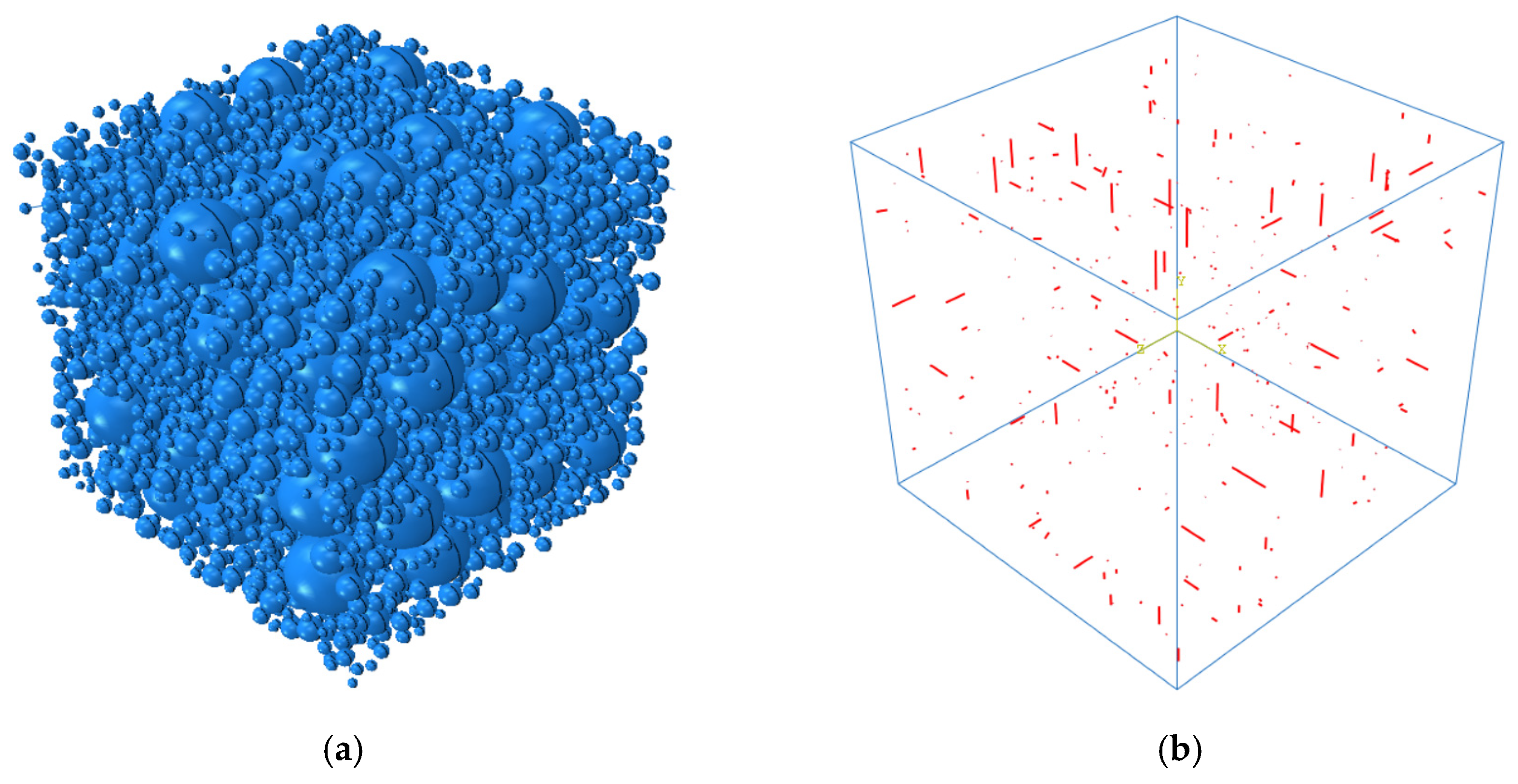
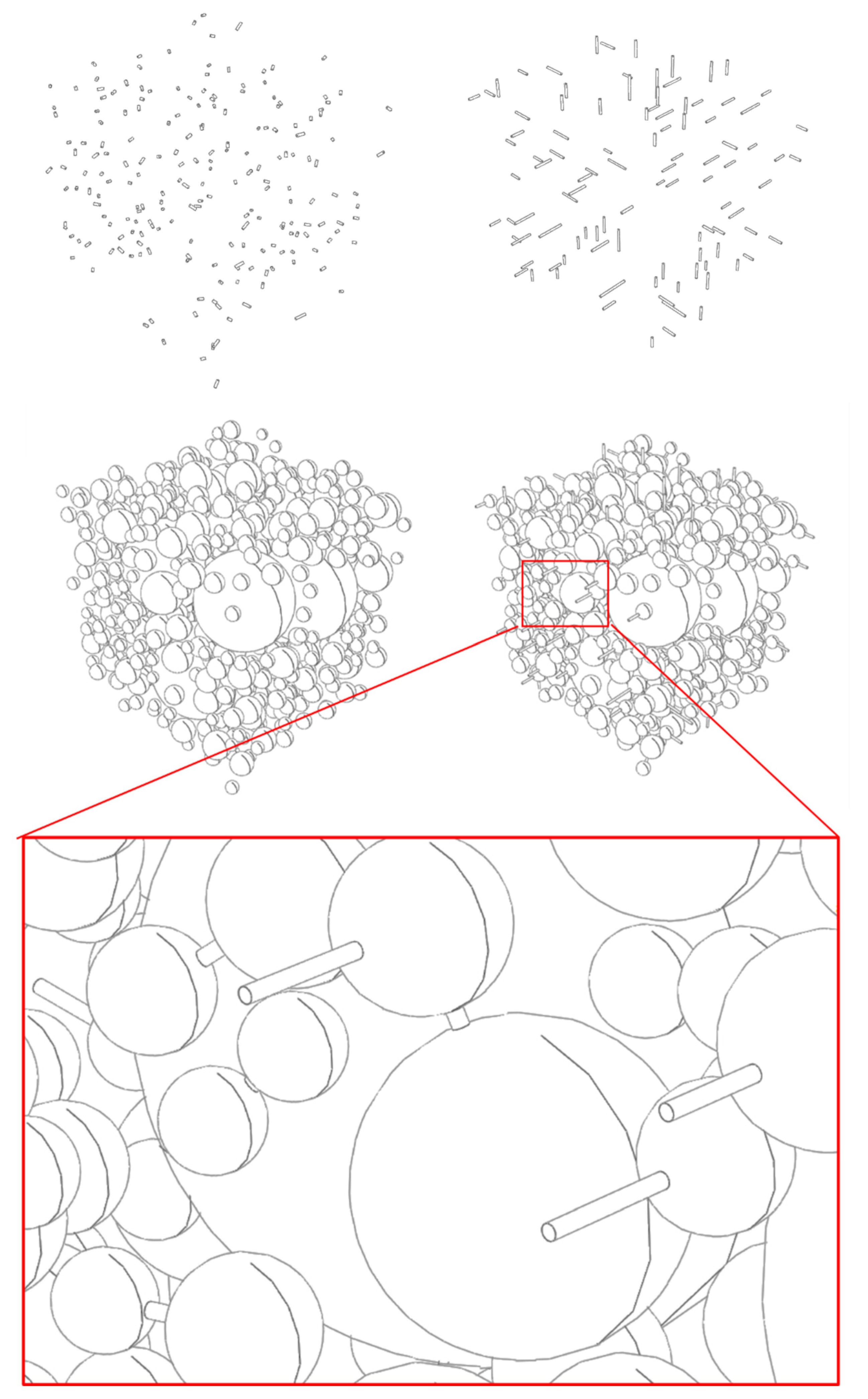
After completing the placing of aggregates and generation of cracks, they need to be combined with cement mortar to complete the construction of the model. Relevant studies have shown that the internal ion diffusion coefficient of aggregates is much smaller than that in mortar. For the convenience of calculating and analyzing the model, it is assumed that chloride ions will not penetrate into the aggregates. That is, chloride ion diffusion only occurs in the cement mortar and cracks. Therefore, it is necessary to establish a separate model for the cement mortar part to complete the mesh generation. The basic logic is to use Boolean operations to remove the aggregates and cracks from the concrete block, and the remaining part is the mortar. After completing the mesh generation for the mortar and crack parts, they are then combined together to obtain the final random aggregate model. The distribution of aggregates is shown in
Figure 1(a), and the distribution of cracks is shown in
Figure 1(b).
To accurately simulate the diffusion transfer between different material models, it is necessary to define the contact surface between different materials. For complex contact surfaces, accurate selection of the contact position is required. This model considers the contact surface between each crack entity and cement mortar. It is necessary to set the primary plane and secondary plane separately for the selection of contact surfaces. In this article, the mortar part of concrete material is selected as the primary plane, and the crack surface is selected as the secondary plane. Considering the interface transition zone, it is also necessary to set the contact surface between it and cement mortar. For mass diffusion problems, the contact type is selected as a bonded constraint.
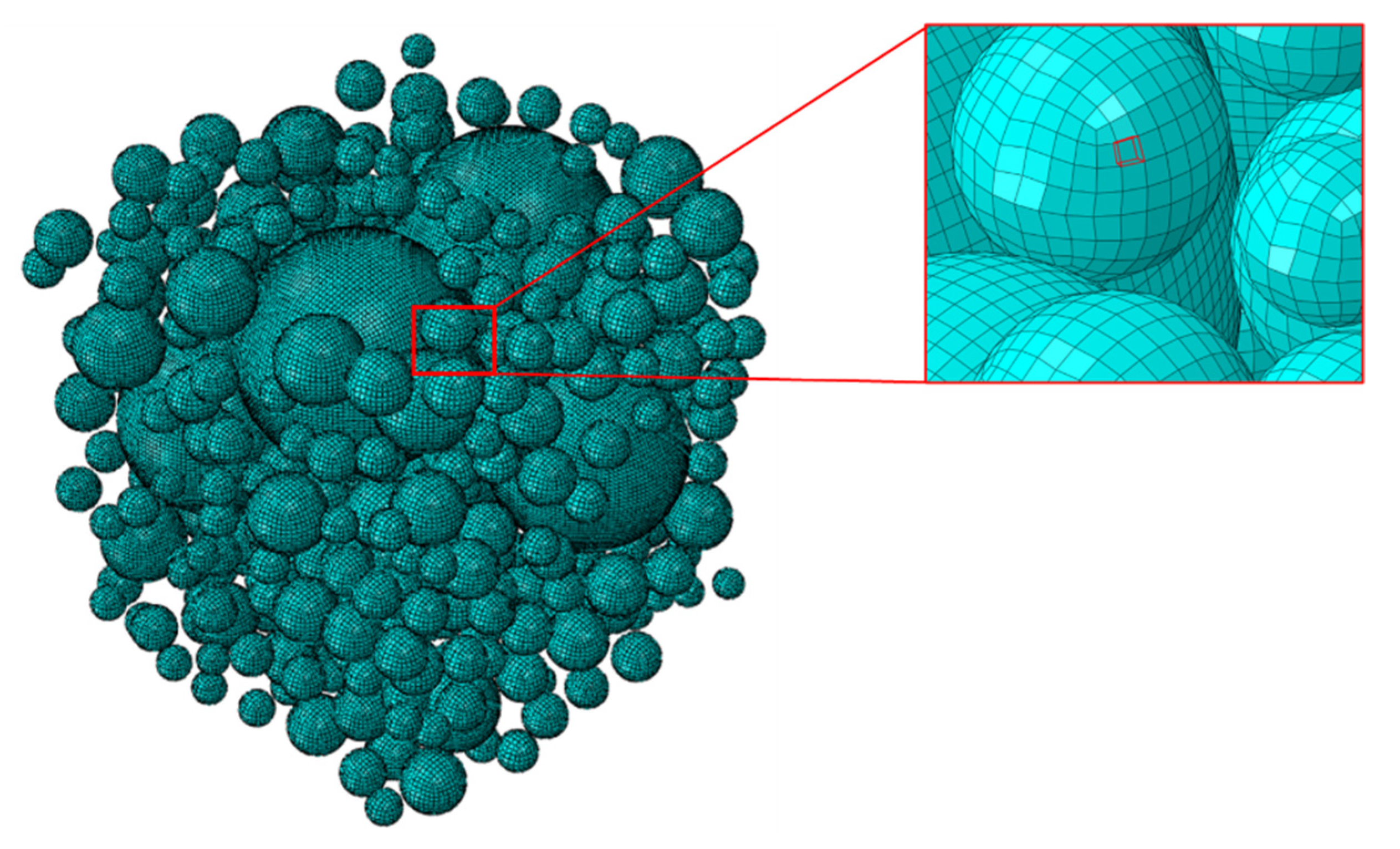
Mesh generation is crucial for finite element calculations. This article completes the automation of modeling and analysis for complex but regular models. Priority is given to methods that are easy to implement and adjust in code selection. For random aggregate models, consideration should be given to the contact surfaces of different materials. The actual model is complex and cannot use structured mesh technology. Therefore, unstructured mesh is selected for mesh generation. The mesh shape selects tetrahedral mesh to adapt to the more complex spherical structure. Element types need to meet the requirements of mass diffusion analysis. Ensure sufficient accuracy of integration. After completing the mesh generation, a mesh check should be performed. In the example, the mesh is a complex unstructured tetrahedral mesh, which may have a small grid volume leading to the failure of finite element analysis. Therefore, a mesh check is necessary. Adjust mesh parameters to avoid unfavorable mesh generation.
In addition, this article also considers the influence of the interface transition zone. In the actual modeling process, the interface transition zone is represented by a thin shell with a very small thickness outside the aggregate particle model. It is necessary to establish a thin shell model with actual volume. The logic of modeling is to establish a sphere collection with a radius slightly larger than the aggregate particles, and then subtract the aggregate model from it through Boolean cutting calculation. Then we can get the model of the interface transition zone, which appears as a thin shell with a very small thickness. Directly using tetrahedral mesh for free partitioning is very prone to produce adverse mesh. Therefore, it is necessary to perform segmentation operation on the solid model. The cutting method selected in this article is to use three planes to cut the solid element under the local coordinate system with the model itself as the origin. After cutting, the sphere shell can be divided into high-quality mesh through structured mesh or sweeping mesh.
3. Verification
For the chloride ion diffusion coefficient in mortar and ITZ, we adopt the formula based on experimental results provided in the literature [
30]. The chloride ion diffusion coefficient in mortar can be calculated using Equation (1).
where
Dref is set as 5.259×10
-12m
2/s,
V denotes volume fraction of aggregates,
S is maximum size of aggregates,
t represents ion diffussion time, and
f1,
f2,
f3 are correction factors considering diffusion time, volume fraction of aggregates, and maximum size of aggregates, respectively.
The influence of cracks on chloride ion diffusion characteristics in concrete can be divided into three stages. The first stage is when the crack width is less than the threshold value. At this point, the influence of cracks on chloride ion diffusion behavior can be neglected. The chloride ion diffusion capacity inside the crack is equivalent to the surrounding uncracked concrete. That is to say, the chloride ion diffusion inside the crack is equivalent to the uncracked concrete. The second stage is as the crack width increases to the upper limit of crack width. The chloride ion diffusion capacity inside the crack gradually increases. This means that the chloride ion diffusion capacity inside the crack is greater than the surrounding uncracked concrete. The third stage is when the crack width in the concrete exceeds the upper limit of crack width. The chloride ion diffusion capacity inside the crack is equivalent to the diffusion capacity in a free solution. This indicates that the accumulation of chloride ions on the surface of cracks is equivalent to the erosion surface. As a result, lateral diffusion of chloride ions occurs at the crack.
The literature [
30] prepared concrete samples with aggregates having a volume fraction of 10%, 20%, and 30%. The volume of the concrete samples was 100 mm × 100 mm × 100 mm. The coarse aggregate size ranged from 4.75 mm to 31.5 mm. The samples were subjected to chloride ion diffusion experiments for 180 days. This article established a numerical model similar to the experiments in the literature to verify the numerical simulation results of the model.
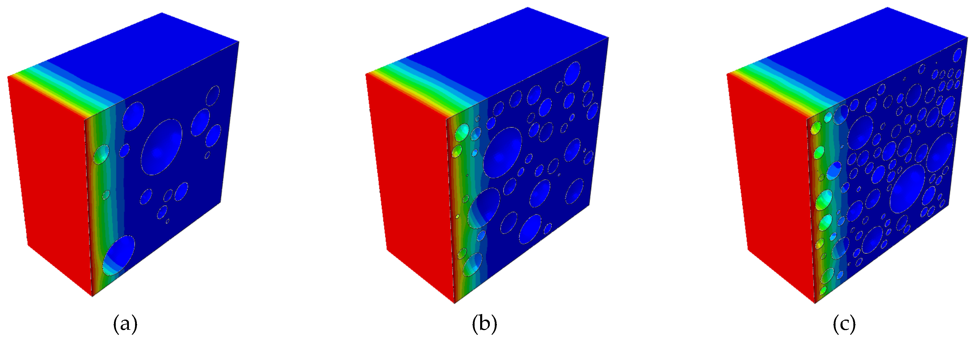
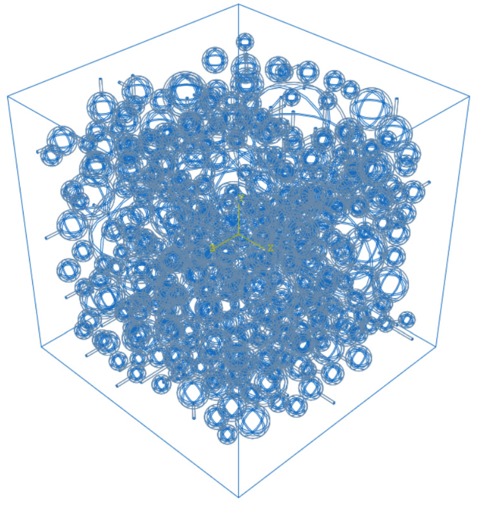
When considering the time-dependent effect of chloride ion diffusion coefficients in material parameters, the calculated results of Equation (1) were given. The surface chloride ion concentration used the fitted expression from the literature, and a three-dimensional random aggregate model was established, as shown in
Figure 2. The diffusion simulation results after 180 days are shown in
Figure 3. For the random aggregate model, the randomly distributed aggregates block the diffusion of chloride ions. Therefore, the chloride ion concentration at a certain depth cross-section is uneven, as shown in
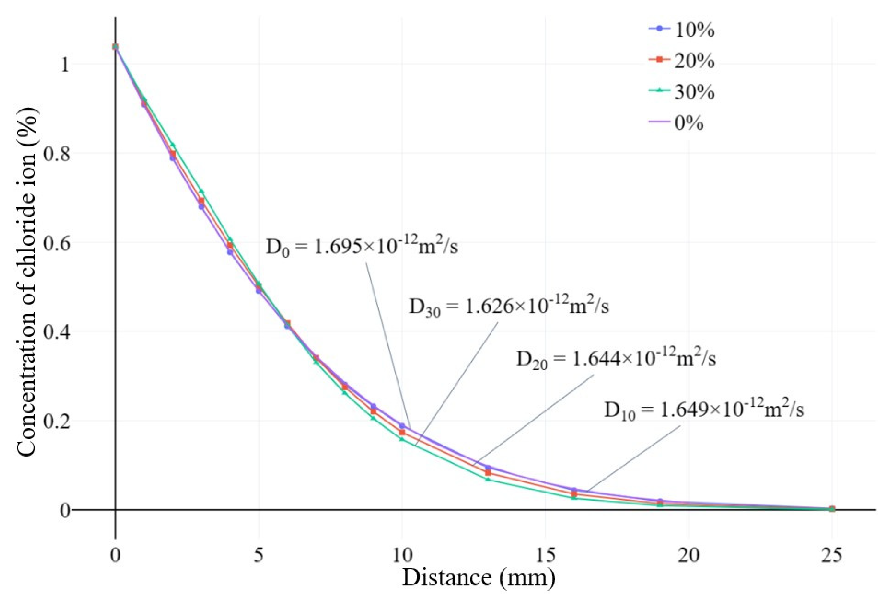
Figure 4. The apparent chloride ion diffusion coefficient of the numerical model simulation results was calculated based on the principle of fitting the natural diffusion experiment to calculate the concrete chloride ion diffusion coefficient.
In this article, finite element nodes at different depth cross-sections were selected, and the simulation results of all nodes were read and averaged to obtain the diffusion concentration of chloride ions at that depth.
The concentration curve of chloride ion at different depths is shown in Figure 27. By statistically analyzing the data of model cross-section element nodes at different depths and taking the average value, the chloride ion concentration inside the specimen at that depth can be obtained. Based on Fick’s second law, the fitting of this result can be used to obtain the apparent chloride ion diffusion coefficient of concrete. The simulation results of the model agree with the experimental results in literature [
30].
5. Conclusions
Based on the numerical simulation of chloride ion diffusion using a random aggregate model, this chapter further studies the influence of aggregates on the diffusion of chloride ions in concrete. In addition, the numerical simulation also takes into account the influence of micro-cracks and interface transition zones associated with the aggregates. The higher the bulk ratio of aggregates, the smaller the apparent chloride ion diffusion coefficient of concrete. This is due to the hindrance effect of aggregates on chloride ion diffusion in concrete. Aggregate filling lengthens the diffusion path of chloride ions. The larger the aggregate particle size, the more significant its hindrance effect on chloride ions. When aggregates are unevenly distributed, chloride ion diffusion is faster in areas with fewer aggregates, while it is slower in areas with high density aggregates. In concrete with unevenly distributed aggregates, the chloride ion diffusion coefficient cannot reflect local areas where chloride ion diffusion is faster.
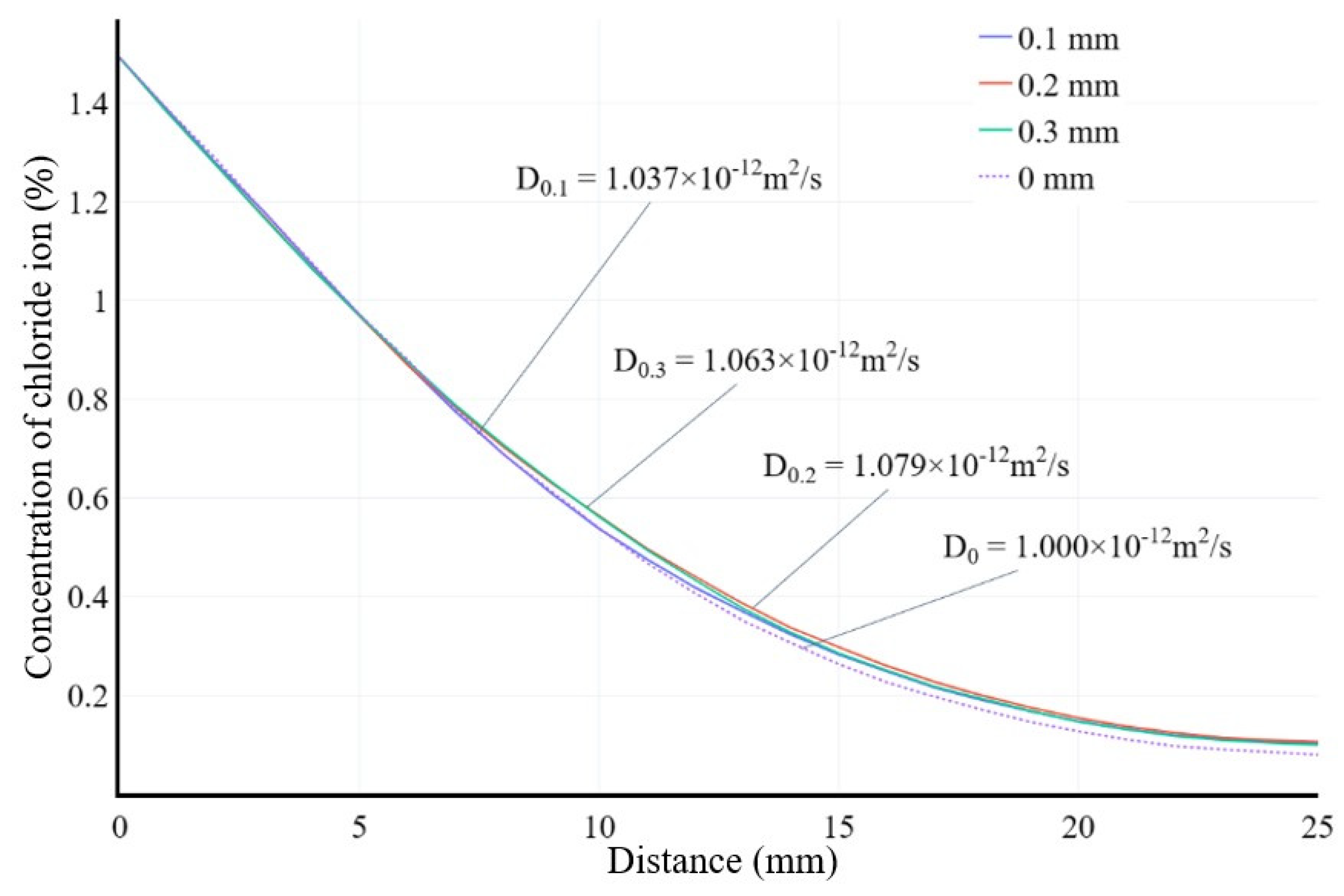
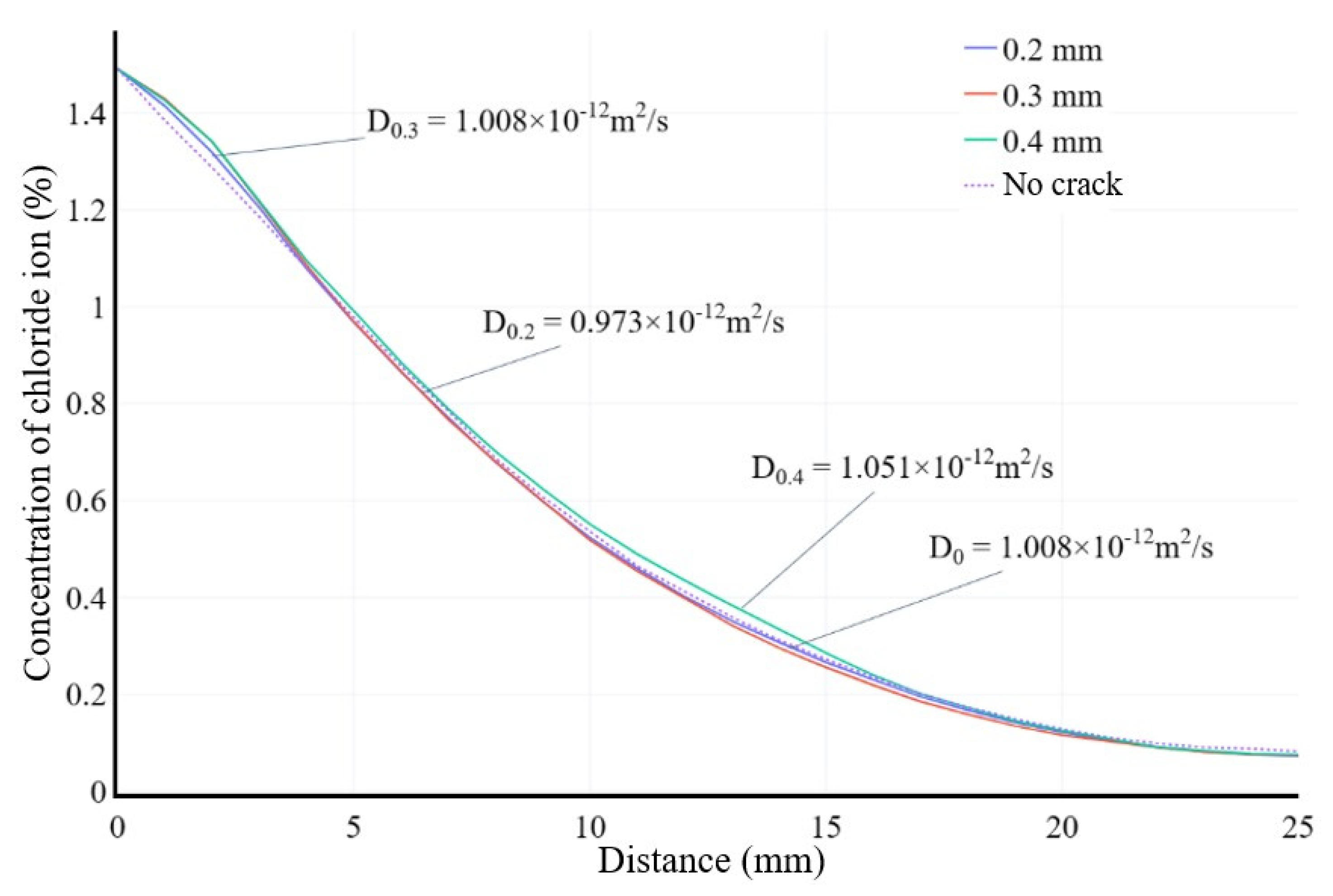
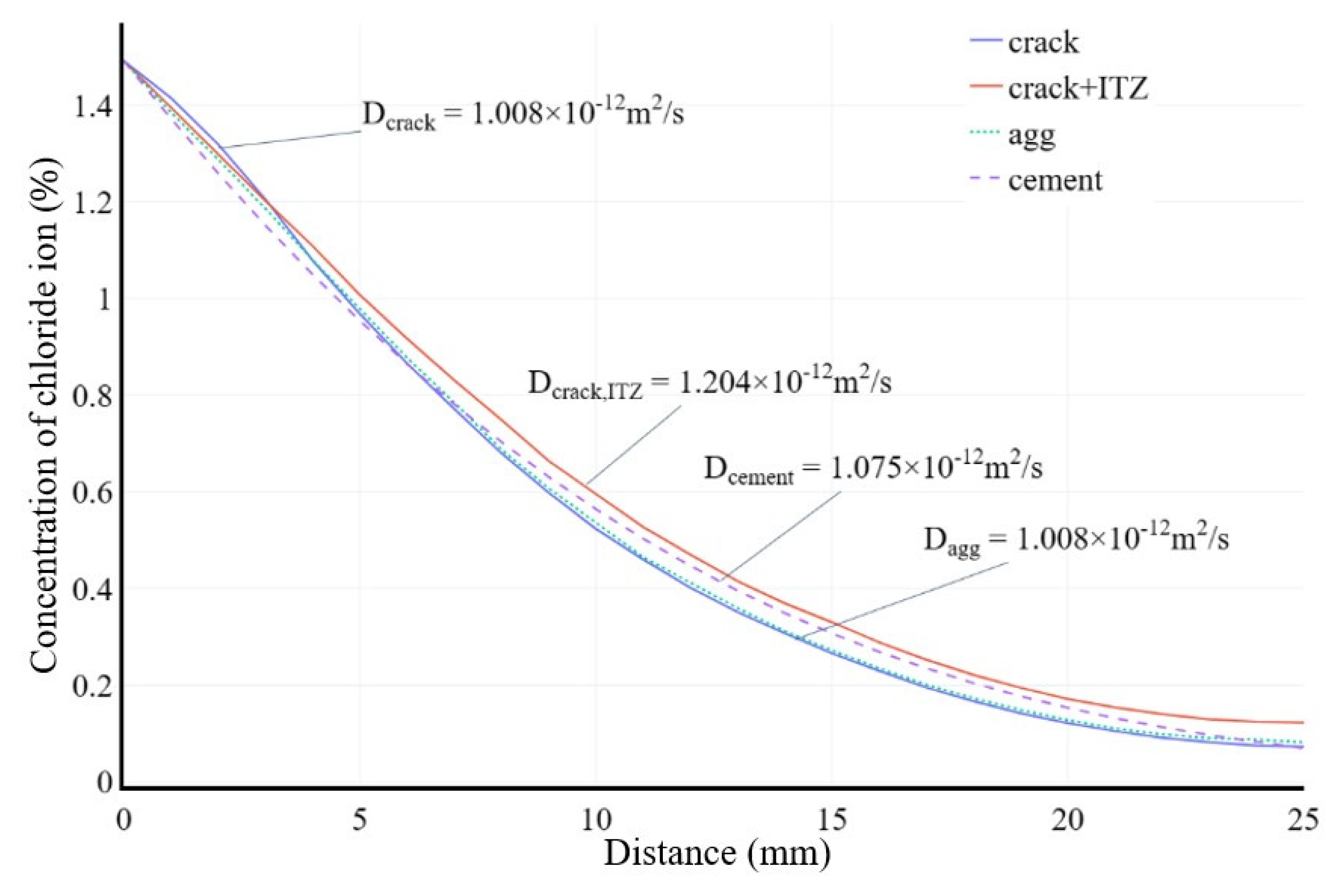
Taking into account the interface transition zone between the aggregates and the mortar, its diffusion coefficient has a greater impact on the chloride ion diffusion coefficient of concrete. The ITZ portion can accelerate the diffusion of some of the chloride ions that are partially accumulated around the aggregates. Within a certain thickness range, the diffusion model with consideration of ITZ always has a higher internal chloride ion concentration than the model without considering ITZ. The diffusion coefficient of chloride ions in micro-cracks will increase the apparent chloride ion diffusion coefficient of concrete when the width of micro-cracks extends to a certain degree. However, if the crack width is small, the complex crack network formed by non-perforated cracks inside prolongs the propagation path of chloride ions in concrete. Instead, it will reduce the apparent chloride ion diffusion coefficient of concrete. In addition, the microscopic structure composed of micro-cracks and ITZ provides a fast diffusion path for chloride ions, which can significantly increase the apparent chloride ion diffusion coefficient of concrete.
Figure 1.
The distribution of (a) aggregates, and (b) cracks.
Figure 1.
The distribution of (a) aggregates, and (b) cracks.
Figure 2.
Random aggregate models with volume fractions of (a) 10%, (b) 20%, and (c) 30%.
Figure 2.
Random aggregate models with volume fractions of (a) 10%, (b) 20%, and (c) 30%.
Figure 3.
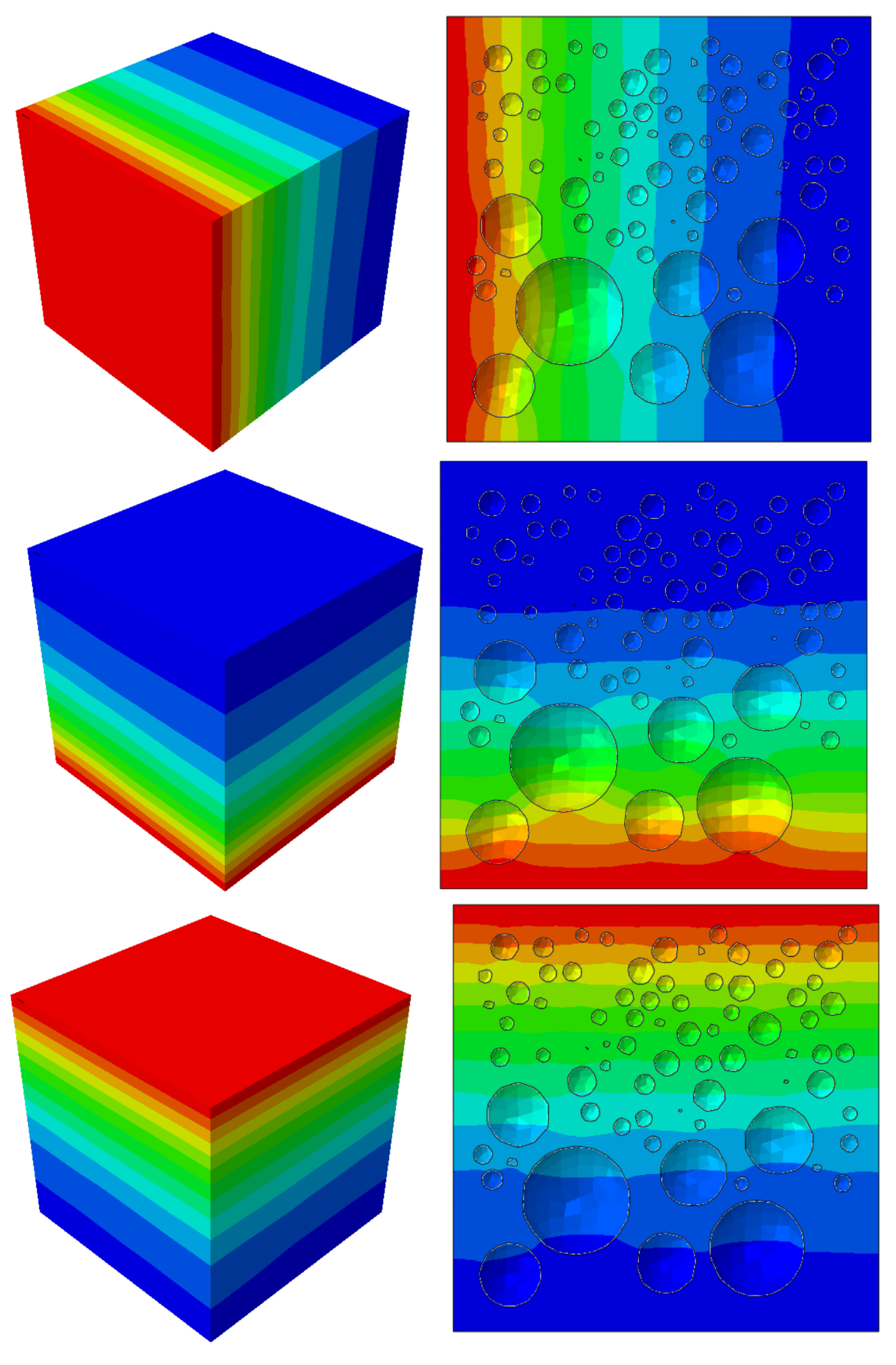
The numerical simulation results of concrete specimens with aggregate volume fractions of (a) 10%, (b) 20%, and (c) 30% after 180 days of chloride ion diffusion experiments.
Figure 3.
The numerical simulation results of concrete specimens with aggregate volume fractions of (a) 10%, (b) 20%, and (c) 30% after 180 days of chloride ion diffusion experiments.
Figure 4.
Chloride ion diffusion curves of concrete specimens after 180 days of chloride ion diffusion experiments.
Figure 4.
Chloride ion diffusion curves of concrete specimens after 180 days of chloride ion diffusion experiments.
Figure 5.
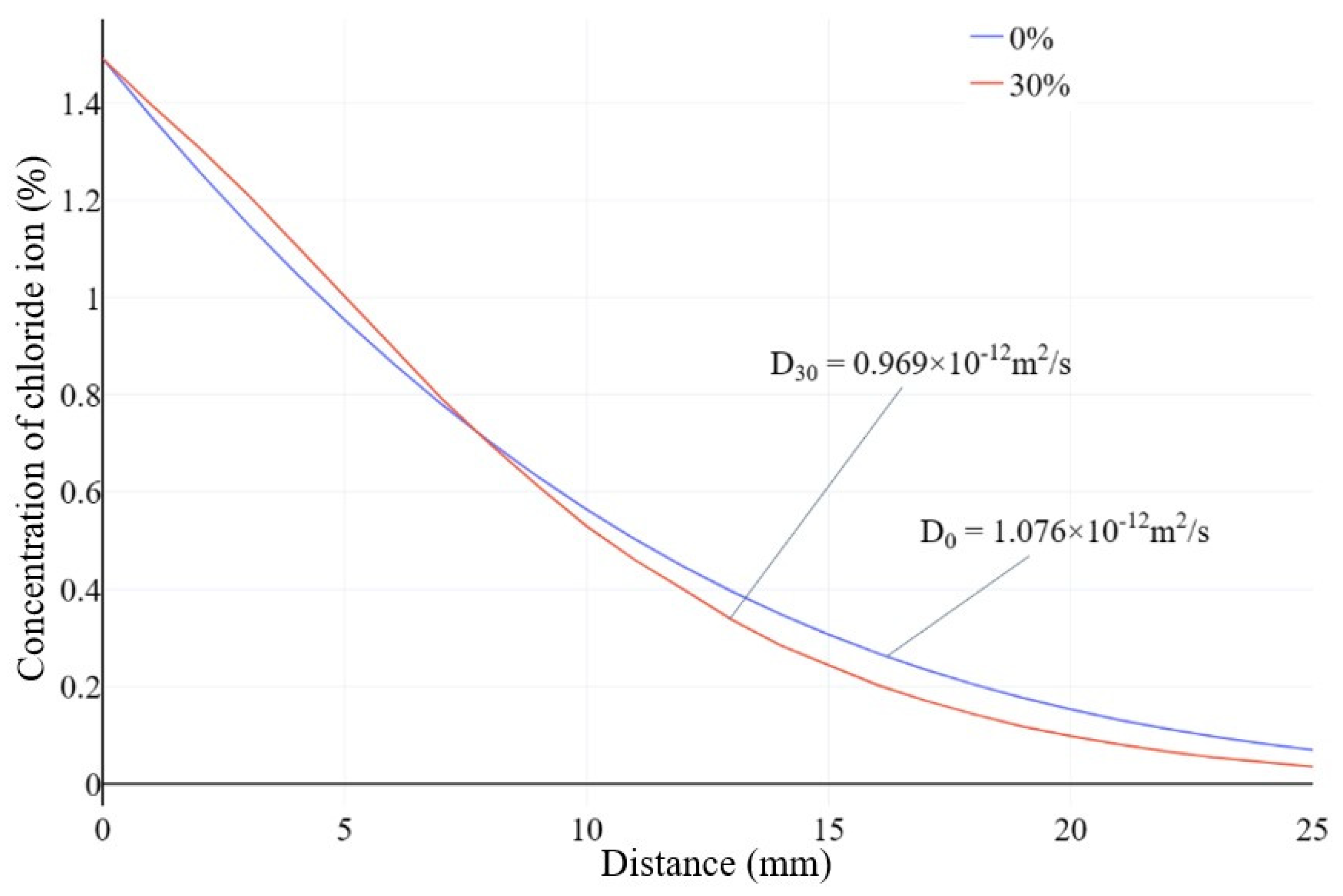
Chloride ion diffusion curves of concrete specimens after 720 days of chloride ion diffusion experiments.
Figure 5.
Chloride ion diffusion curves of concrete specimens after 720 days of chloride ion diffusion experiments.
Figure 6.
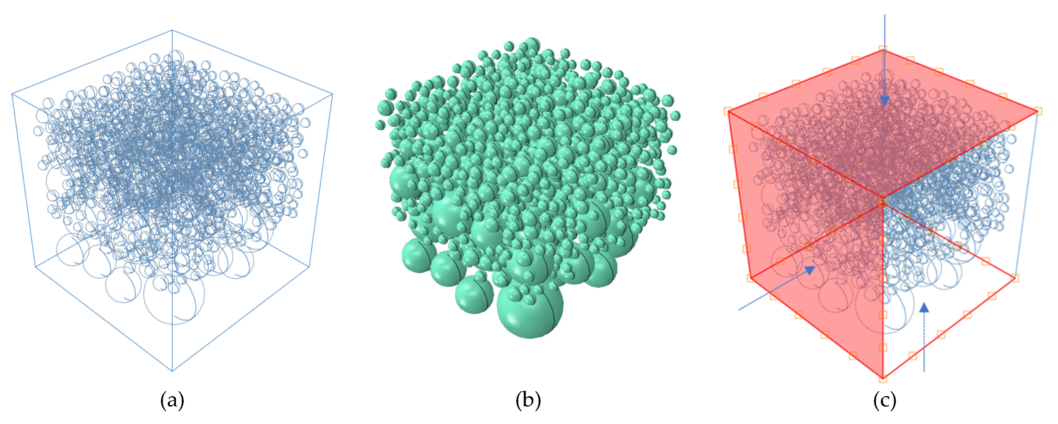
(a) Random aggregate model; (b) uneven distribution of aggregates; (c) Boundary conditions.
Figure 6.
(a) Random aggregate model; (b) uneven distribution of aggregates; (c) Boundary conditions.
Figure 7.
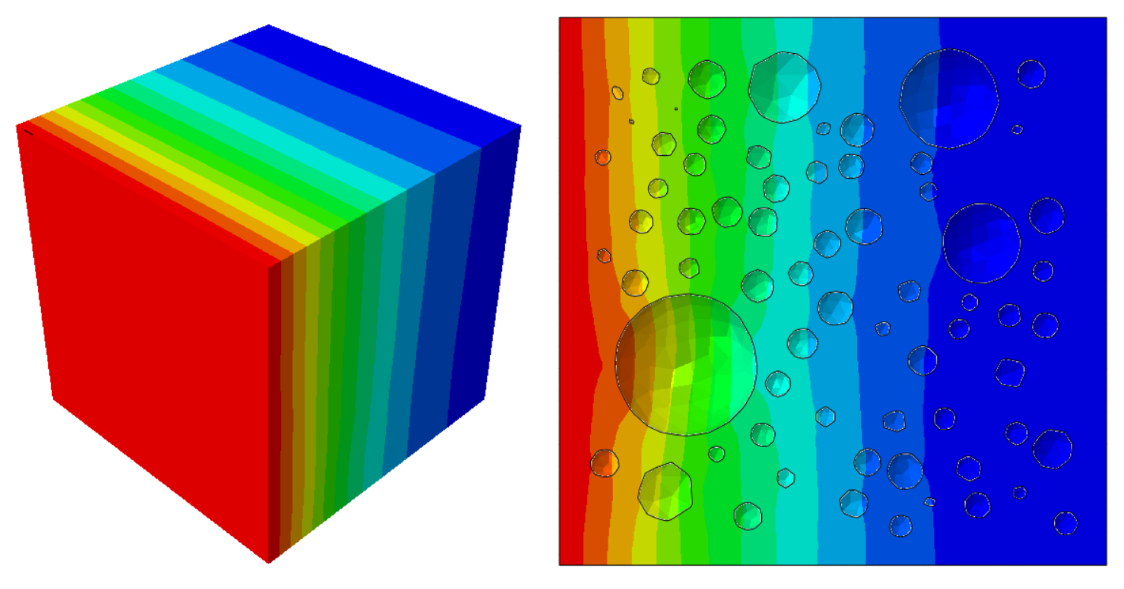
The numerical simulation results of concrete specimens with different aggregate volume fractions.
Figure 7.
The numerical simulation results of concrete specimens with different aggregate volume fractions.
Figure 8.
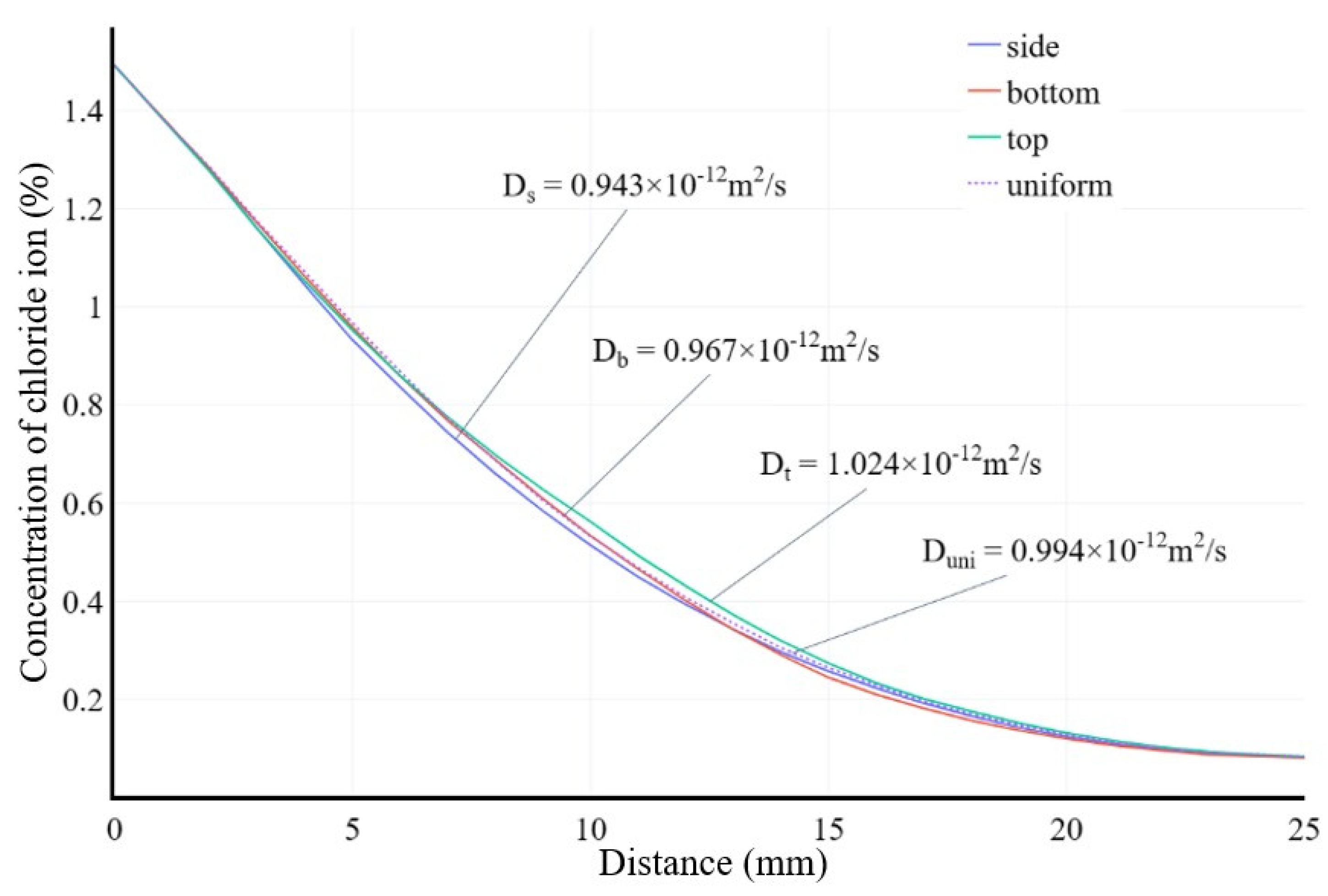
Chloride ion diffusion curves of concrete specimens after 720 days of chloride ion diffusion under different boundary conditions.
Figure 8.
Chloride ion diffusion curves of concrete specimens after 720 days of chloride ion diffusion under different boundary conditions.
Figure 9.
Chloride ion diffusion curves of concrete specimens considering ITZ.
Figure 9.
Chloride ion diffusion curves of concrete specimens considering ITZ.
Figure 10.
Schematic diagram of random internal cracks, edge cracks, and aggregates.
Figure 10.
Schematic diagram of random internal cracks, edge cracks, and aggregates.
Figure 11.
Chloride ion diffusion curves of concrete specimens considering internal cracks.
Figure 11.
Chloride ion diffusion curves of concrete specimens considering internal cracks.
Figure 12.
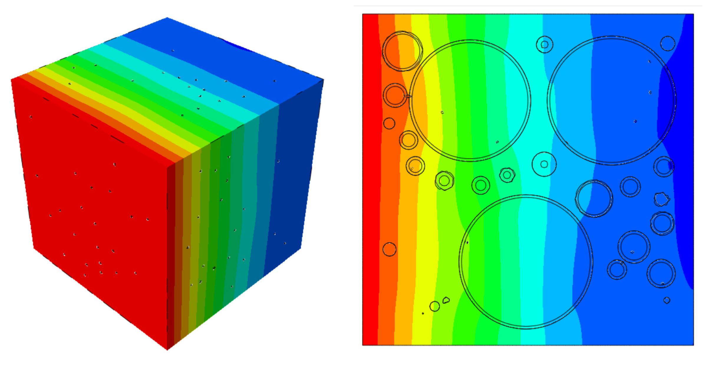
The randomly distributed aggregate model considering both cracks and ITZ.
Figure 12.
The randomly distributed aggregate model considering both cracks and ITZ.
Figure 13.
Mesh generation of ITZ.
Figure 13.
Mesh generation of ITZ.
Figure 14.
Simulation results of the randomly distributed aggregate model considering both cracks and ITZ.
Figure 14.
Simulation results of the randomly distributed aggregate model considering both cracks and ITZ.
Figure 15.
Chloride ion diffusion curves of the randomly distributed aggregate model considering both cracks and ITZ.
Figure 15.
Chloride ion diffusion curves of the randomly distributed aggregate model considering both cracks and ITZ.
Figure 16.
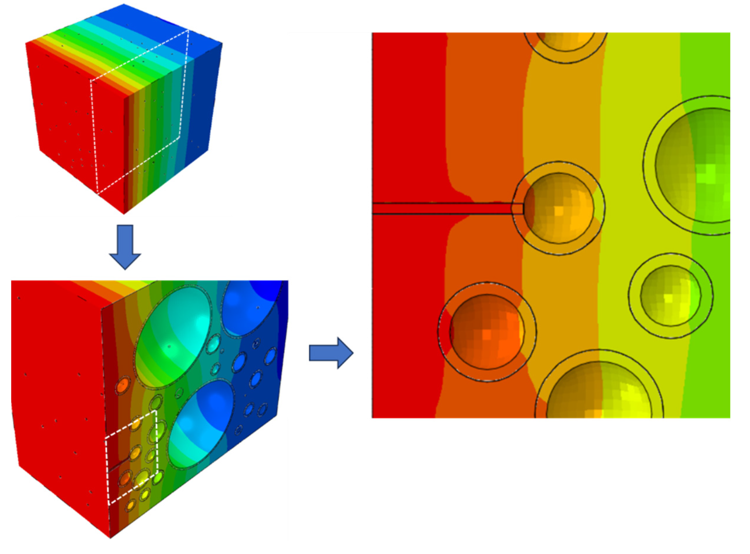
Local section of the randomly distributed aggregate model considering both cracks and ITZ.
Figure 16.
Local section of the randomly distributed aggregate model considering both cracks and ITZ.
