1. Introduction and Literature Review
In a demolition project involving post-tensioned or prestressed concrete beams, engineers must prioritize several key factors. Safety is predominant, requiring the implementation of appropriate safety measures for workers and the public, including protective gear, safety barriers, and thorough training. Structural integrity poses a significant challenge due to the high-tension forces within the beams, necessitating careful analysis and a demolition plan to mitigate the risk of collapse. Environmental impact must also be considered, with measures taken to address hazardous materials and ensure proper waste disposal. Cost-effective planning is crucial, as special equipment and techniques may be necessary, while adherence to a realistic schedule helps minimize disruption to the local community. Additionally, engineers should prioritize sustainability, striving to reduce waste through recycling or repurposing materials. In summary, a comprehensive approach considering safety, structural integrity, environmental impact, cost, schedule, and sustainability is essential for the successful completion of such demolition projects, mitigating risk and minimizing impact.
The demolition industry has two main resources available to support the safe and efficient demolition of structures: Occupational Safety and Health Administration (OSHA) 1926 Subpart T–Demolition [
1] and The Demolition Manual by National Demolition Association (NDA) Safety & Health Resources [
2]. By leveraging these resources, industry professionals can stay up-to-date on industry trends and best practices, and ensure that they have the knowledge and tools they need to complete demolition projects successfully.
OSHA has regulations and guidelines related to the demolition of prestressed concrete structures. OSHA’s Construction Standard for Demolition [
1] requires that employers develop a written demolition plan that includes the methods and procedures to be used to remove concrete, including prestressed concrete. The plan must be developed by a qualified engineer or competent person with experience in demolition. The standard also requires that prestressed concrete be identified and evaluated prior to demolition. Employers must ensure that the demolition methods used do not create hazardous conditions, such as sudden collapse due to the high-tension forces within the structure.
The Demolition Manual by the National Demolition Association (NDA) [
2], correlated to the OSHA Standard [
1], provides guidance and best practices for the demolition industry. The manual covers a wide range of topics related to demolition, including safety, environmental regulations, equipment selection, project management, and more. The manual provides guidance on how to evaluate the structural integrity of prestressed concrete structures prior to demolition, as well as the appropriate methods and equipment for removing prestressed and post-tensioned concrete beams and other elements. In addition, the manual includes information on the safety considerations involved in the demolition of prestressed concrete, including the potential for sudden collapse due to the high-tension forces within the structure. In summary, engineers should pay attention to safety, structural integrity, environmental impact, cost, schedule, and sustainability in a demolition project involving post-tensioned or prestressed concrete beams. Careful planning and attention to these factors can help ensure the successful completion of the project while minimizing risk and impact.
Although the above-mentioned documents provide detailed instructions, there is limited literature on the study and investigation of the complex behavior of post-tensioned systems during demolition. Felstead A. E. and Lindsell P. [
3] reported on the controlled demolition of a PT beam, offering insights into PT beam design behavior. Notably, the beam depth in their study was 2.6 feet, which accounts for 37% of the depth of the beams discussed in this paper. Anumba C. et al. [
4] provided general information on demolition techniques, albeit without specific focus on PT concrete demolition. This paper presents a discussion of PT system design and application, followed by a case study description of the demolition of large PT beams. Information is provided on concerns related to beam behavior during cutting, aiding engineers in decision-making for similar projects. Results from a computerized model are presented to analyze stresses during beam loading, particularly during soil removal to access the top of the beams. The demolition approach is then outlined, including the drilling technique used to carefully detension groups of tendons prior to saw-cutting of the beam section. Horizontal cracking in the beams during drilling is explained from a design and theoretical standpoint, emphasizing the bursting effect in PT anchorage zone design.
2. Design and Application
In this specific type of concrete structure, the terms “prestressed” and “post-tensioned” are used. The distinction relates to the timing of steel tensioning prior to the application of typical external loads, such as dead load, live load, or lateral loads. The tensioned steel elements are typically high-strength steels and are commonly referred to as cables, tendons, or strands. For consistency, the term “tendon” will be used hereafter in this paper.
In prestressed concrete, the tendons are placed under tension prior to the pouring of the concrete. Typically, this is accomplished by placing steel in a mold, tensioning it, and then pouring concrete over it. Once the concrete has hardened, the tension is released, and some of the steel’s tension is transferred to the concrete in compression which helps to counteract the tensile forces in concrete that the beam will experience during use. The Double T beams, along with other elements of a precast parking garage, are common examples of a precast-prestressed system.
In post-tensioned concrete, tendons are placed into ducts and concrete is poured. After the concrete has hardened, hydraulic jacks are used to tension the tendons, putting the concrete into compression and the steel into tension. Therefore, the term ‘prestressed’ applies to both prestressed and post-tensioned concrete because steel tensioning occurs prior to the application of service loads in both techniques. However, in a prestressed system, the tendons are stressed prior to the casting of concrete, whereas in a post-tensioned system, the tendons are stressed after the concrete is poured. There are two distinct types of post-tensioned concrete systems: unbonded and bonded. Unbonded post-tensioning utilizes bare tendons encased in a plastic sheath, allowing the steel to move freely relative to the structure. To prevent corrosion and reduce friction, the steel is grease-coated. Bonded post-tensioning utilizes tendons placed within corrugated metal ducts. After stressing the tendons, cementitious grout is injected into the duct, creating a bond between the grout, tendons, and concrete.
3. Project Description
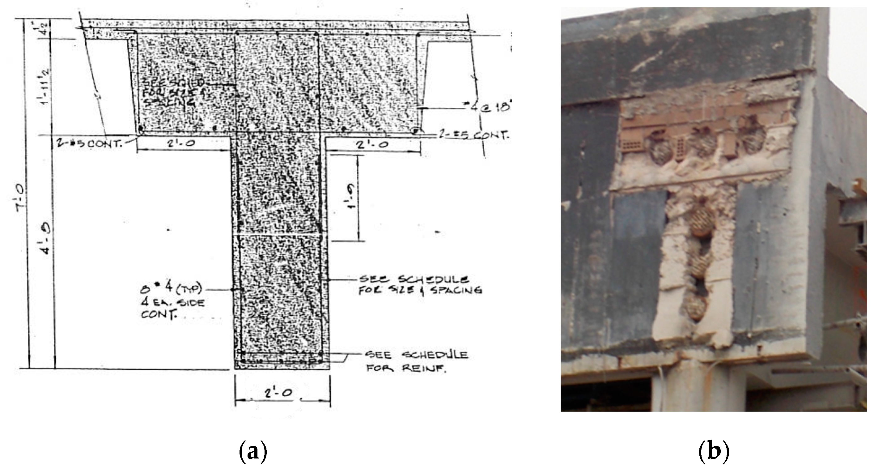
The project was situated in the southern part of Atlanta. The objective of the demolition was to remove the below-ground, two-story building’s long-span roof while preserving the integrity of the first floor. The central plan of the building was rectangular, measuring approximately 104 feet in one direction (aligned with the post-tensioned beams) and 110 feet in the other direction, with 4 bays of 27.67 feet each. Constructed in the early 1980s, the building was in relatively good condition. However, the decision to remove the roof was made to facilitate a change in the building’s function as part of a larger renovation project. A cross-section of the beam is depicted in
Figure 1(a). The roof was covered by approximately three feet of topsoil, a layer of gravel, and a layer of grass. According to structural drawings, the concrete strength at 28 days was 6000 psi. The estimated average self-weight of the roof topping was 250 psf. Consequently, this imposed a dead load of 6667 lb/ft on the beam. The self-weight of the T-shaped beam was approximately 3560 lb/ft, assuming a unit weight of 150 pcf for the reinforced concrete
The roof system between the girders consisted of a cast-in-place concrete waffle (ribbed) system, 28 inches thick, with a 4.5-inch continuous slab and 18-inch-wide ribs, resulting in an average concrete thickness of 18 inches. The distance between the edges of adjacent T-beams was approximately 21.5 feet, all covered by the waffle slab system. The estimated average self-weight of the waffle slab was 225 psf, resulting in a dead load of 4838 lb/ft added to the self-weight of the T-beam. Therefore, the total dead load (self-weight) of concrete applied on the PT beams was 8398 lb/ft. Adding the dead load from the topsoil, the total dead load became 15065 lb/ft.
A total of 160 tendons were used, distributed among six ducts with a diameter of 4 inches.
Figure 1(b) depicts the end-view of the beam. The number of tendons per duct varied to ensure that the center of gravity of the tendons aligned with the centroid of the T-section. To analyze the beam’s condition at different loading stages, a computer model was created using Ram Concept software from Bentley Systems, Inc [
5]. The primary focus was to determine stress levels at the top and bottom of the T-beam when the dead load of topsoil is removed. Additionally, the 24-inch diameter columns were included in the modeling.
The results of the analysis, presented as maximum stresses at the mid-span of the beam, are summarized in
Table 1 and compared with the limits specified in ACI-318-11[
6], which was the applicable code at the time of demolition. The service loading includes the self-weight of concrete, the weight of topsoil, and a 100 psf live load. Both loading conditions incorporate the PT balance loading. The bottom stress under service loading falls within the range of
, and the compressive stress at the bottom when the topsoil is removed does not exceed the limit of
3600 psi. This analysis confirms that the PT beam was adequately designed to support the heavy load of the roof and topping, and that the compressive stress when the topping is removed is within the limit and thus not of concern.
4. Demolition Approach
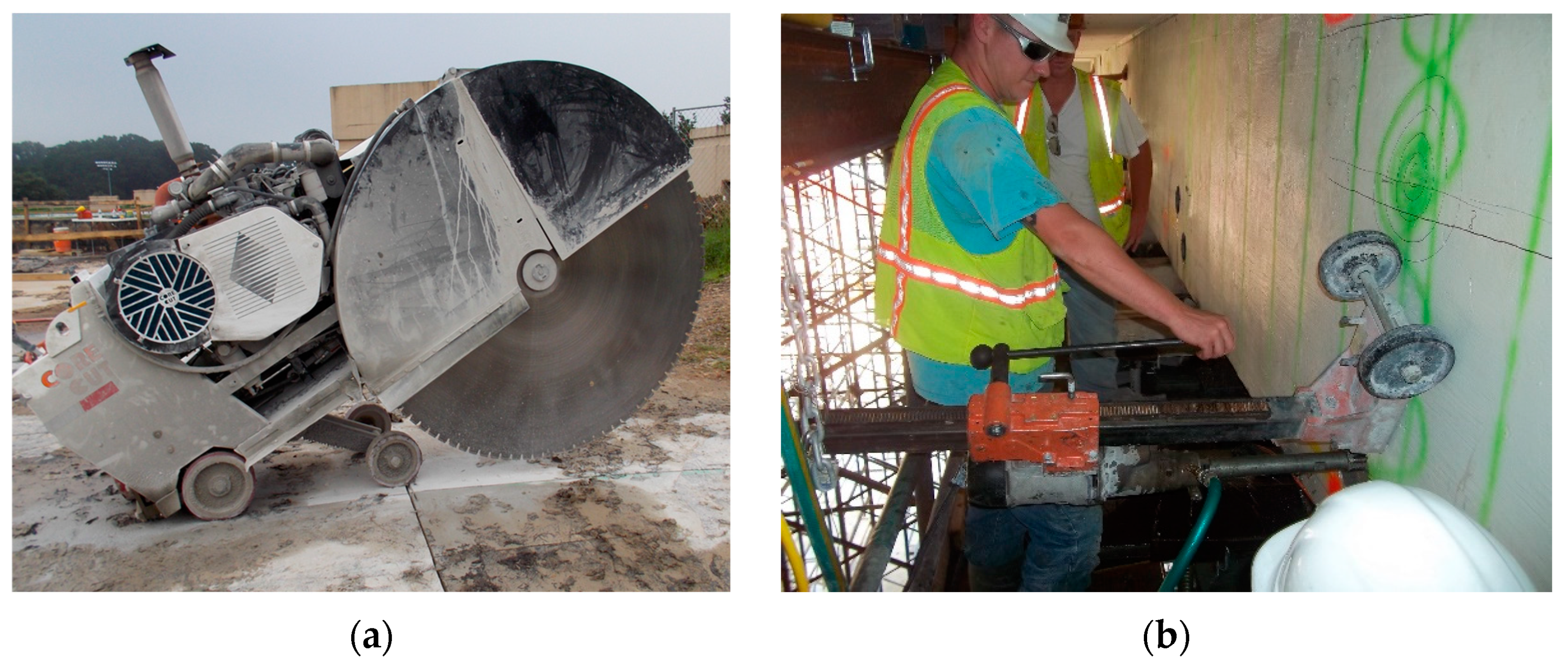
The demolition was carried out using a modern and well-maintained fleet of equipment, operated by skilled personnel. Large hydraulic and diesel-operated slab saws, as well as cable or wire saws, were employed to cut through the 28-inch-deep joists of the waffle slab and the 7-feet-deep concrete PT beams.
Figure 2(a) depicts the placement of the large saw atop the slab to penetrate the thick concrete. The drilling operation conducted on the side of the beam, using a 6-inch-diameter hydraulic drill, is depicted in
Figure 2(b). The materials slated for demolition were initially reduced in height and dimensions as necessary to ensure safe removal. Subsequently, they were further reduced in size to facilitate efficient transport from the site.
During the saw-cutting of the roof slab, initial cuts were made through the 6’-0” wide top section of the girder. This pre-cut, with a depth of 28 inches, facilitated the efficient use of a cable/wire saw once the adjoining sections of the roof were removed. Subsequently, a wire saw was employed from the top of the girder, wrapped around the 2’-0” x 4’-8” bottom section of the beam (
Figure 1(a)), to complete the cutting of the entire beam section.
The length of the segments of the beam being cut was determined by the capacity of the crane and the distance of each piece relative to the crane’s location, which was on one side of the building. Segments were removed from front to back, with each segment decreasing in size and weight to accommodate the reach and lift capacity of the truck crane. Depending on the weight of each segment, four anchors were carefully designed with attention to the impact effect, and drilled on the top to be connected to the crane hook.
Figure 3 illustrates the lifting of a cut segment.
Prior to commencing the demolition, the roof structure was shored according to an approved shoring plan. The shoring calculations and plans underwent thorough review by the engineering sectors of the various involved parties. Special attention was given to the bracing of the shoring legs to ensure the stability of the entire system. This step is crucial in this type of demolition. The stability of the shoring system must be considered in terms of both the overall stability of the entire system and the local stability of secondary elements. The latter involves the potential for web crippling of the “I” or “W” shape steel beams commonly used in shoring systems. Local loads applied from either a structural element above the beam or the shoring post below the beam can cause this localized buckling of the web. This effect is sometimes overlooked in shoring design, so it is recommended that engineers take it seriously and evaluate it thoroughly.
The engineers involved in this project, with their expertise in PT design and construction, considered two scenarios regarding the behavior of the PT beams during the demolition process. One possibility was that the tendons were not adequately grouted in their ducts, which could lead to the sudden and dangerous popping out of heavy anchors when a group of tendons is de-tensioned. To mitigate this risk, it was decided to drill through the concrete and cut one duct at a time. Additionally, special safety measures were implemented in the area in front of the beams to prevent any damage or injury in case an anchor popped out.
Alternatively, if the grouting was done without imperfections, cutting an entire section of the beam using saw cutting or wire cutting could pose a significant risk of bursting the beam perpendicular to the cutting line. This bursting effect is similar to what is described in ACI-318 and PTI standards. In this scenario as well, drilling the ducts one at a time was deemed necessary to minimize risks.
To address both above-mentioned scenarios, an innovative approach was adopted: cutting each duct individually, one by one, using a powerful drill. A specialized 6-inch diameter drill was employed for the drilling process. This drill, being heavy, required mounting to the concrete using anchor bolts. Based on the tendon profile provided in the structural drawings, it was determined that the first drilling should be performed at the top of the beam near the end. This decision was made because three ducts were expected to be closer to the top of the beam, as depicted in picture 1 (b). Drilling near the end would also mitigate the risk of anchors popping out, especially if the grouting was not done adequately.
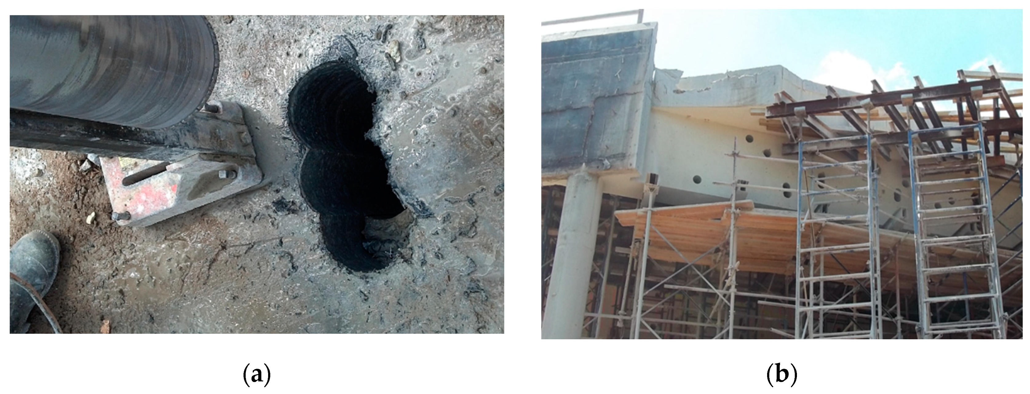
Figure 4(a) depicts the drill and the holes on the top of one of the beams. It is evident from this image that three holes were drilled to locate one duct. The challenge of locating the PT ducts became more pronounced, especially when drilling on the side of the beam, as seen in
Figure 4(b), which shows many holes drilled to locate tendon ducts. This is also evident in
Figure 3 showing several holes in a cut segment. Although Ground Penetrating Radar (GPR) scanning of concrete was employed to locate the rebar and tendon ducts, many ducts were not positioned close enough to the surface to be accurately located. This issue arose due to discrepancies between the design drawings and the as-built conditions. Such discrepancies need to be carefully considered when undertaking demolition projects of this nature.
5. Discussions: Challenges and Insights
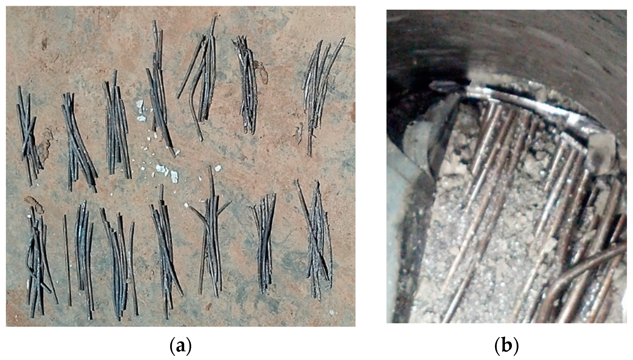
The task of drilling, cutting, and demolishing the large PT beams in this project, with its inherent complexity, posed several challenges but also yielded valuable insights into construction issues and the behavior of PT beams from both design and engineering perspectives. A review of one of the report provided by the field operations manager sheds light on some of these challenges. According to the report, coring progress has been hindered by several factors, including difficulties in locating ducts, leading to guesswork and inefficiencies. The actual number of cores required were two to three times higher than initially estimated, for example with three cores needed to locate just one duct, each up to 26 inches deep. Moreover, the presence of four to six 1-inch diameter steel rebars on top necessitated careful drilling. Extensive cord lengths, reaching several hundred feet to the power box, have also posed logistical challenges including placing strain on the drills. Additionally, when reaching the duct and starting to cut strands, the loose pieces, 3 to 4 inches long, rotated, resulting in drilling through the same strand multiple times. (
Figure 5) When this occurred, the drill had to be pulled out, the hole cleaned, and the loose strands removed before starting again. This necessitated frequent drill removal, hole cleaning, and strand removal, adding to operational complexities.
During the drilling operation on the side of the beams, the technicians observed a recurring phenomenon characterized by loud booms and the development of horizontal cracks. This raised concerns among the technicians, who speculated that these booms might be caused by the sudden separation and settling of the beams, particularly after cutting a certain number of tendons. However, upon further analysis, considering the complex behavior of the beams under these conditions, it was explained that the horizontal cracks are a result of the phenomenon known as “bursting.” In post-tensioned (PT) beams where numerous tendons are stressed simultaneously, a significant tension force is developed perpendicular to the direction of the tendons. This phenomenon, well-described by Lin T. Y. [
7], is addressed in design manuals and standards, such as the PTI Manual [
8] and ACI 318 Standard [
6,
9], under the term ‘anchorage zone.’ Guidelines provided by Breen et al. [
10] offer simplified equations to determine the bursting force in the anchorage zone. To resist this tension force, special reinforcement, as outlined in ACI 318 [
6,
9], should be designed and placed behind the anchors in the anchorage zone.
The act of cutting multiple tendons during drilling through a duct applies a significant force to the beam, similar to bursting. Unlike the anchorage zone with adequate reinforcement, the absence of substantial reinforcement in a location along the beam exacerbates the development of horizontal cracking. Once the concrete cracks, the tension is released, and since the beam is no longer subjected to the same loading conditions, the concern regarding the cracking diminishes. This explanation aligns with theoretical principles and offers insights into the observed behavior, highlighting the importance of understanding structural responses during demolition processes to ensure structural integrity and safety.
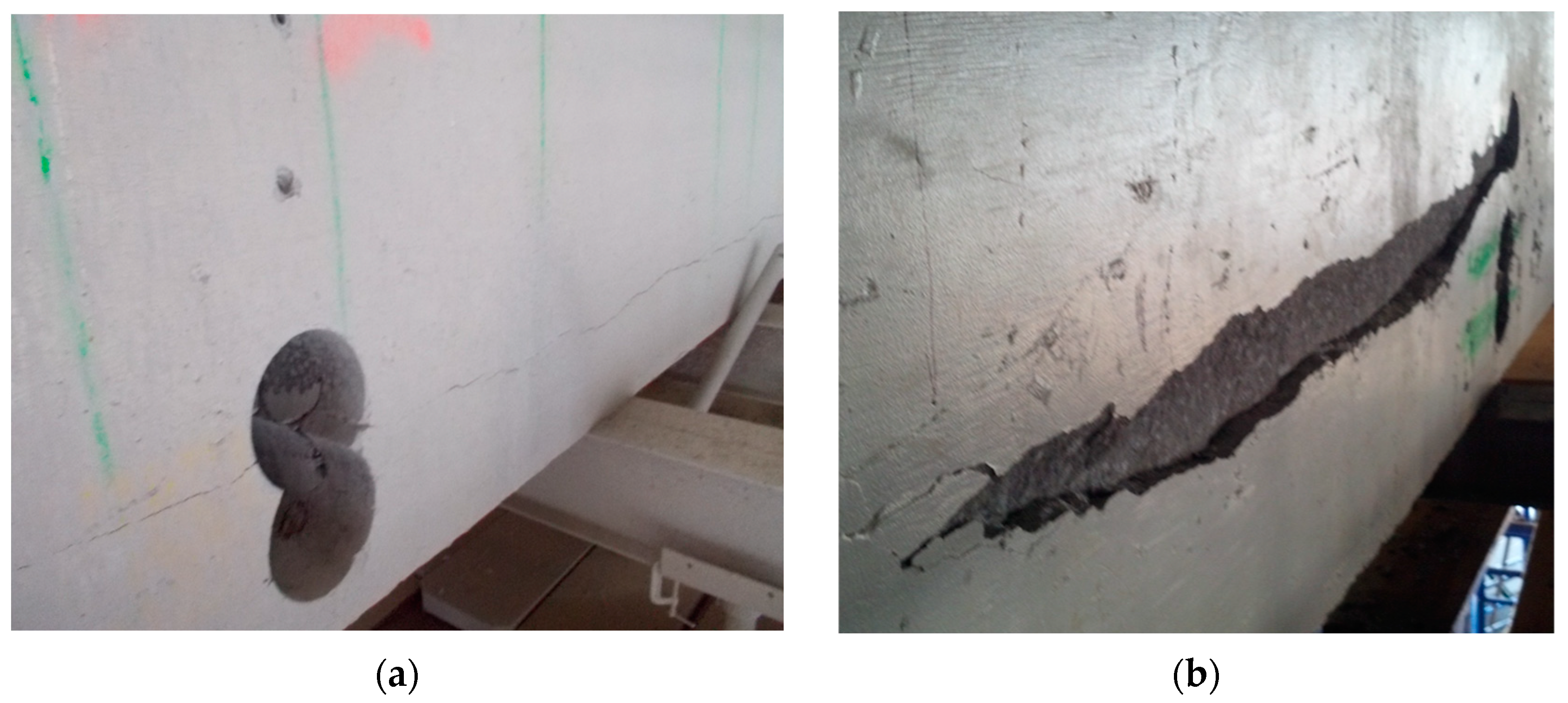
The horizontal cracking observed on the side of the beam after cutting tendons in a duct is depicted in
Figure 6(a). Additionally,
Figure 6(b) illustrates the spalling of concrete in another beam. The presence of stirrups of #4 at 12” on center along the beam has proven effective in preventing catastrophic bursting of concrete and has limited the width of cracking.
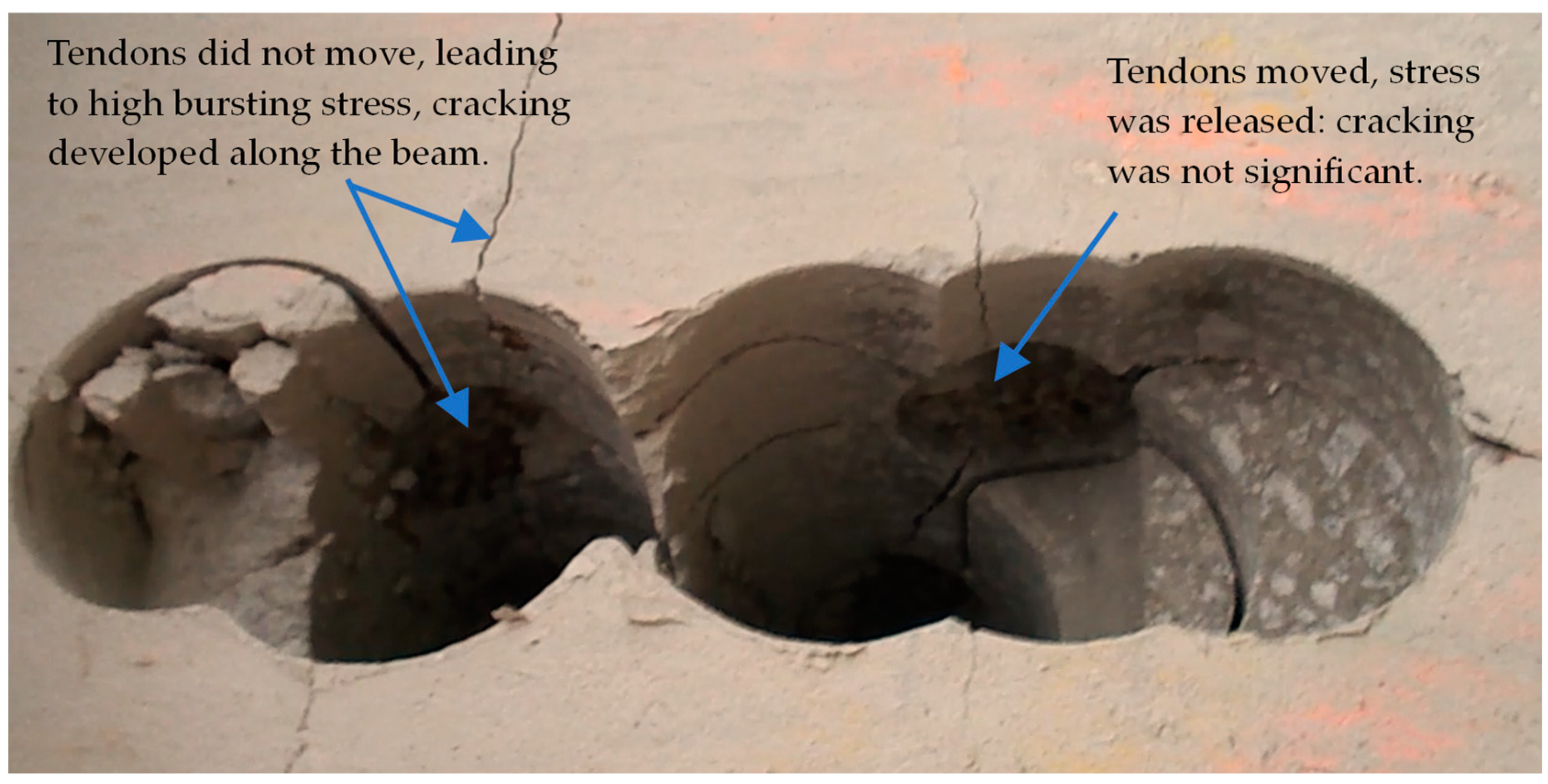
Depending on the effectiveness of the grouting, the tendons inside the duct moved approximately up to ½ inch in some cases, while in others, there was no movement, as illustrated in
Figure 7.
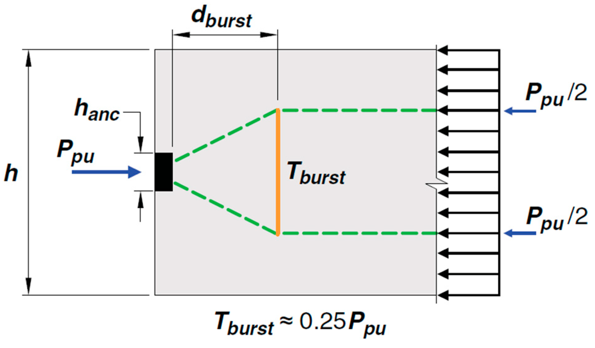
The significance of the tension stresses (bursting) behind the anchorage zone is a function of the ratio of the size of the anchor and the depth of the beam (
hanc / h) as specified in ACI 318-19. In the case of cutting one duct, this ratio is the duct diameter (4”) to the beam depth (84”), which is negligible. Hence,
Tburst can be considered as 25% of the released force of tendons in one duct, as illustrated in
Figure 8 provided by ACI 318-19. Assuming there are 25 tendons in one duct, and utilizing the typical force of 27 kips per tendon (commonly used in PT design), the calculated bursting force would amount to 0.25 x 25 x 27 = 169 kips. This represents a substantial tension force capable of inducing cracking, especially upon sudden release.
It’s crucial to note that the scenario of cutting one duct, as encountered in this demolition project, differs slightly from the depiction in
Figure 8. When a duct is cut, the released force is transferred to the concrete over a certain length of the duct, albeit suddenly and with impact. Therefore, the concept of bursting force behind an anchor (
Figure 8) is used solely to explain the phenomenon of bursting that results in horizontal cracking in the beam during demolition.
6. Conclusions
This paper describes the novel task of demolishing multiple large-span, deep post-tensioned concrete beams without causing damage to the remaining structure of a real project. The process of demolishing the PT beams in this project showcased the utilization of an innovative and successful technique, executed through meticulous engineering work and the implementation of thorough safety measures. Concerns regarding the effectiveness of grouting, or the potential release of significant forces if the tendons were effectively bonded prompted the decision to drill and cut each duct’s tendons individually along the beams. Drill cutting of each duct then revealed that the grouting was relatively effective, which resulted in producing loud sounds followed by horizontal cracking along the beams’ sides, confirming the phenomenon known as the bursting effect in PT design. While it would have been more cost-effective and easier to cut the entire beam section using giant saws without de-tensioning tendons through drilling, the occurrence of bursting cracks indicated that cutting the entire section, with 160 tendons, at once would have posed a significant risk of dangerous beam bursting. Such an occurrence would have severely compromised crew safety and potentially hindered or delayed the demolition process.
The following are some additional conclusions that can be drawn from the effective demolition technique process described in this paper:
- a)
It is crucial to accurately design a shoring system capable of supporting the weight of entire systems with a safety factor of at least three. Both the global stability of the entire system and the local stability of secondary elements must be considered when evaluating the stability of the shoring system.
- b)
It is necessary to evaluate the original design of the PT beams to determine the status of the beam design in terms of stresses and existing reinforcement. Beam loading and support conditions are subject to change during the demolition process, requiring special attention.
- c)
Following the evaluation described in the previous item, the sequence of demolition can be determined. In this project, the highly pre-stressed beams supported approximately three feet of soil and a thirty-foot waffle-type concrete slab. Due to the uplift effect of pre-stressing, the removal of soil and slab prior to cutting the tendons would result in significant compressive stress at the bottom of the beam. Consequently, it was necessary to first shore the entire structure, considering all existing loads, and then cut the tendons. Following the removal of the soil, the concrete slab was cut, and the beams were segmented with a saw.
- d)
To cut the concrete and lift the heavy pieces, heavy machinery and high-capacity cranes were employed with care. The ground conditions and soil compaction were carefully considered in areas where cranes had to be moved and operated.
- e)
The capacity and capability of the equipment used to cut, lift, and relocate heavy pieces determines the size and shape of the demolished elements.
The successful operation described in this paper demonstrates the use of an appropriate technique, accurate analysis and calculations, and appropriate equipment.
7. Acknowledgments
The authors extend their appreciation to Kyle Bontreger PE, SE; Rodmy Montero; Keith Brock; and Marty VanHorn from Tendon Systems, LLC, now part of CMC (Commercial Metals Com-pany), for providing some information from their archive. The first author served as the Chief Engineer at Tendon Systems, LLC, when this project was undertaken. The analysis and design for this project were solely conducted by him.
Author Contributions
Conceptualization, M. Jonaidi; Methodology, M. Jonaidi, A. Kaplan and A. Keyvanfar; Software, M. Jonaidi; Validation, M. Jonaidi, A. Kaplan and A. Keyvanfar; Formal analysis, M. Jonaidi; Investigation, M. Jonaidi, A. Kaplan and A. Keyvanfar; Resources, M. Jonaidi and A. Kaplan; Data curation M. Jonaidi, A. Kaplan and A. Keyvanfar; Writing—original draft preparation, M. Jonaidi; Writing—review and editing, M. Jonaidi, A. Kaplan and A. Keyvanfar; Visualization, M. Jonaidi, A. Kaplan and A. Keyvanfar; Supervision, M. Jonaidi; Project administration, M. Jonaidi; Funding acquisition, N/A. All authors have read and agreed to the published version of the manuscript.” Please turn to the CRediT taxonomy for the term explanation. Authorship must be limited to those who have contributed substantially to the work reported.
Funding
This research received no external funding
Data Availability Statement
No new data were created.
Acknowledgments
The authors extend their appreciation to Kyle Bontreger PE, SE; Rodmy Montero; Keith Brock; and Marty VanHorn from Tendon Systems, LLC, now part of CMC (Commercial Metals Company), for providing some information from their archive. The first author served as the Chief Engineer at Tendon Systems, LLC, when this project was undertaken. The analysis and design for this project were solely conducted by him.
Conflicts of Interest
The authors declare no conflicts of interest.
References
- Occupational Safety and Health Administration (OSHA). Safety and Health Regulations for Construction, Demolition: 1926 Subpart T, https://www.osha.gov/laws-regs/regulations/standardnumber/1926/1926SubpartT, 2013.
- National Demolition Association (NDA), Safety-Health-Resources, https://www.demolitionassociation.com/Industry-Resources/Safety/Safety-Health-Resources, 2023.
- Felstead, A. E.; Lindsell, P. Controlled Demolition of a Post-Tensioned Beam. Concrete 1981, 15, 20–23. [Google Scholar]
- Anumba, C.; Abdullah, A.; Fesseha, T. Selection of Demolition Techniques. Structural Survey 2003, 21, 36–48. [Google Scholar] [CrossRef]
- Bentley Systems, Incorporated. RAM Concept—Structural Analysis and Design Software. Bentley Systems, V8i Release 5.0.1, 2012.
- American Concrete Institute (ACI). Building Code Requirements for Structural Concrete (ACI 318-11); American Concrete Institute: Farmington Hills, MI, USA, 2011. [Google Scholar]
- Lin T., Y. Design of Prestressed Concrete Structures, 2nd ed.; John Wiley & Sons: USA, 1963; pp. 242–250. [Google Scholar]
- Post-Tensioning Institute (PTI). Post-Tensioning Manual, 6th ed.; Post-Tensioning Institute: Phoenix, Arizona, USA, 2006. [Google Scholar]
- American Concrete Institute (ACI). Building Code Requirements for Structural Concrete (ACI 318-19); American Concrete Institute: Farmington Hills, MI, USA, 2019. [Google Scholar]
- Breen, J. E.; Burdet, O.; Roberts, C.; Sanders, D.; Wollmann, G.; Falconer, B. Anchorage Zone Requirements for Post Tensioned Concrete Girders. In NCHRP Report 356; Transportation Research Board, National Academy Press: Washington, DC, 1994. [Google Scholar]
|
Disclaimer/Publisher’s Note: The statements, opinions and data contained in all publications are solely those of the individual author(s) and contributor(s) and not of MDPI and/or the editor(s). MDPI and/or the editor(s) disclaim responsibility for any injury to people or property resulting from any ideas, methods, instructions or products referred to in the content. |
© 2024 by the authors. Licensee MDPI, Basel, Switzerland. This article is an open access article distributed under the terms and conditions of the Creative Commons Attribution (CC BY) license (http://creativecommons.org/licenses/by/4.0/).
