Preprint
Review

Unstable Metal Hydrides for Possible on-Board Hydrogen Storage

Altmetrics

Downloads

145

Views

333

Comments

0

A peer-reviewed article of this preprint also exists.

Submitted:

12 April 2024

Posted:

15 April 2024

You are already at the latest version

Alerts
Abstract
Hydrogen storage in general is an indispensable prerequisite for the introduction of a hydrogen energy based infrastructure. In this respect, high-pressure metal hydride (MH) tank systems appear to be one of the most promising hydrogen storage techniques for automotive applications using proton exchange membrane (PEM) fuel cells. These systems bear the potential of achieving a beneficial compromise of comparably large volumetric storage density, a wide working temperature range, comparably low liberation of heat, and increased safety. The debatable term unstable metal hydride stands in the literature short for metal hydrides with high dissociation pressure at comparably low temperature. Such compounds may help to improve the merit of high-pressure MH tank systems. Consequently, in the last few years, some materials for possible on-board applications in such tank systems have been developed. This review summarizes the state-of-the-art developments of these metal hydrides, mainly including intermetallic compounds and complex hydrides and gives some guidelines for future developments. Since typical laboratory hydrogen uptake measurements are limited to 200 bar, a possible threshold for defining unstable hydrides could be a value of their equilibrium pressure of peq > 200 bar for T < 100°C. However, these values would mark a technological future target and most current materials, and those reported in this review, do not fulfill these requirements and need to be seen as current stages of development towards the intended target. For each of the aforementioned categories in the review, special care was taken not only to covers the pioneering and classical research, but also to portrait the current status and latest advances. For intermetallic compounds, key aspects focus on the influence of partial substitution on absorption/desorption plateau pressure, hydrogen storage capacity and hysteresis properties. For complex hydrides, the preparation procedures, thermodynamics and theoretical calculation are presented. Besides, challenges, perspectives, and development tendency of this field are also discussed.
Keywords: 
Subject: Chemistry and Materials Science  -   Materials Science and Technology

1. Introduction

Minimizing the greenhouse gas emissions to limit the global warming has become a global consensus during the past decades. As an energy carrier, hydrogen is a perfect choice to realistically solve the critical issue due to its high energy density (142 MJ/kg), abundant reserves and zero carbon emission if renewably produced [1]. In this scenario, the so-called “hydrogen economy”, a long-term guideline towards a cleaner energy system was proposed, in which hydrogen was introduced into the current energy network to improve the overall cleanliness [2,3,4]. In this system, hydrogen is mainly combined with proton exchange membrane (PEM) fuel cells, in which hydrogen protons generated from the anode transfer through the internal electrolyte to react with oxygen at the cathode, and electricity is produced via electron transfer in the external circuit to drive the vehicles [5]. For on-board PEM fuel cell systems, an efficient and safe hydrogen storage technology guaranteeing a reasonable cruising range (> 500 km) should be developed, which poses a challenge because of the inherent properties of hydrogen gas such as low volumetric energy density, high volatility and strong inflammability [6,7,8]. Current approaches for on-board hydrogen storage mainly include compressed gaseous, cryogenic liquid, liquid organic carriers and solid state materials [9]. However, comprehensive evaluations on the key performances of these techniques leads to the conclusion that no available methods can meet the Department of Energy (DOE) targets [10]. Nowadays, high-pressure gas storage (up to 70 MPa) is the solution for vehicles mainly because of the achieved relative technological maturity, flexible operation, high energy efficiency, and low maintenance costs. Because of the intrinsic physical limitations, further increasing the gas pressure is insufficient for fulfilling the practical requirements for automotive storage. For on-board applications, this high-pressure gas system is only a compromise of the necessities (cruising distance, dead load, etc.) of fuel cell vehicles with the volumetric and/ or gravimetric densities. Although the high-pressure tank systems are widely tested and already used in fuel cell vehicles (e.g. Mirai from Toyota) [11], they still strike many concerns in regard to the volumetric density, safety, cost, etc. By comparison, solid-state hydrogen storage materials show much higher volumetric efficiency and greater safety, while suffer from serious thermodynamic and/or kinetic barriers.
A possible solution for the existing dilemma is to combine light weight high-pressure tank and metal hydrides tank technologies to form a novel hybrid hydrogen storage system, the “high-pressure metal hydride (MH) tank” [12,13,14]. As shown in Figure 1, the packing densities of metal hydride powders are limited due to the nature of powder forms, hence more than 50% of the inner volume of tank system remains empty even when filled with the maximum amount of hydrogen storage material [13]. At this time, filling the free space with high-pressure hydrogen gas will greatly increase the volumetric density and the amount of stored hydrogen. Therefore, this hybrid tank system can realize higher gravimetric and/or volumetric hydrogen density than single solid-state materials or high-pressure gas as long as the volumetric density in the metal hydride stays higher than in the surrounding gas. For instance, under an operating pressure of 35 MPa at 298 K, the amount of stored hydrogen of hybrid tank (100 L) increases from 2.3 kg to 3.7 kg after filling 100 kg of Ti-Cr-Mn alloy [15].
Suitable metal hydrides are vital to the overall performances of hybrid tank. During the hydrogen charging process, the hydrogen storage alloys absorb hydrogen to form metal hydrides and release heat, while during the discharging process, the metal hydrides start to desorb hydrogen and absorb heat as the internal pressure decreases to a value lower than the dissociation pressures. To improve the merits of hybrid tanks, it is essential to employ metal hydrides with high dissociation pressures [16]. On the one hand, high dissociation pressure means low desorption temperature, which is beneficial for the hybrid tank system to supply hydrogen at low temperatures. On the other hand, increasing the dissociation pressure will decrease the heat of reaction (∆RH), which will reduce the thermal effect and improve the heat exchange efficiency of the hydrogen filling/refilling process. Besides, large hydrogen capacity, excellent kinetics, long-term cycle life and favorable heat management are also essential for the envisioned high-pressure MH tank systems. For a 35 MPa hybrid tank system, Mori et al. [17] proposed some target performances for metal hydrides. As shown in Table 1, hydrogen storage density and stability are prior target performances for on-board applications.
To meet the requirements of high-pressure MH tanks, some possible candidates have been developed and tested, mainly including intermetallic compounds and complex metal hydrides. These metal hydrides will decompose under ambient conditions (room temperature, 0.1 MPa pressure). They can only exist at low temperatures and/or under high pressures. The key term “unstable metal hydride” in this review needs some clarification. The term unstable in this context does not mean that the hydride is unstable in the thermodynamic or kinetic meaning, being that there is no energetic barrier towards preventing the decomposition. The word “unstable” in the context of the review is understood as the property of the compound to possess a high plateau pressure at moderate temperatures, resulting in a decomposition of the compound even at technologically high pressures. To comprehensively understand and judge the material base for the developments of suitable metal hydride systems, a review of recent investigations of unstable metal hydrides is essential. Here, we first introduce the developments and applications of intermetallic compounds. Specific examples of partial substitution and related mechanisms are given for AB2-type Laves phase alloys and solid solution alloys. Then, the concepts, synthesis, and theoretical predictions of complex hydrides, including transition metal alanates and transition metal borohydrides, are summarized. Finally, prospects for the existing challenges and future developments are proposed.

2. Intermetallic Compounds

2.1. AB2-Type Laves Phase Alloys

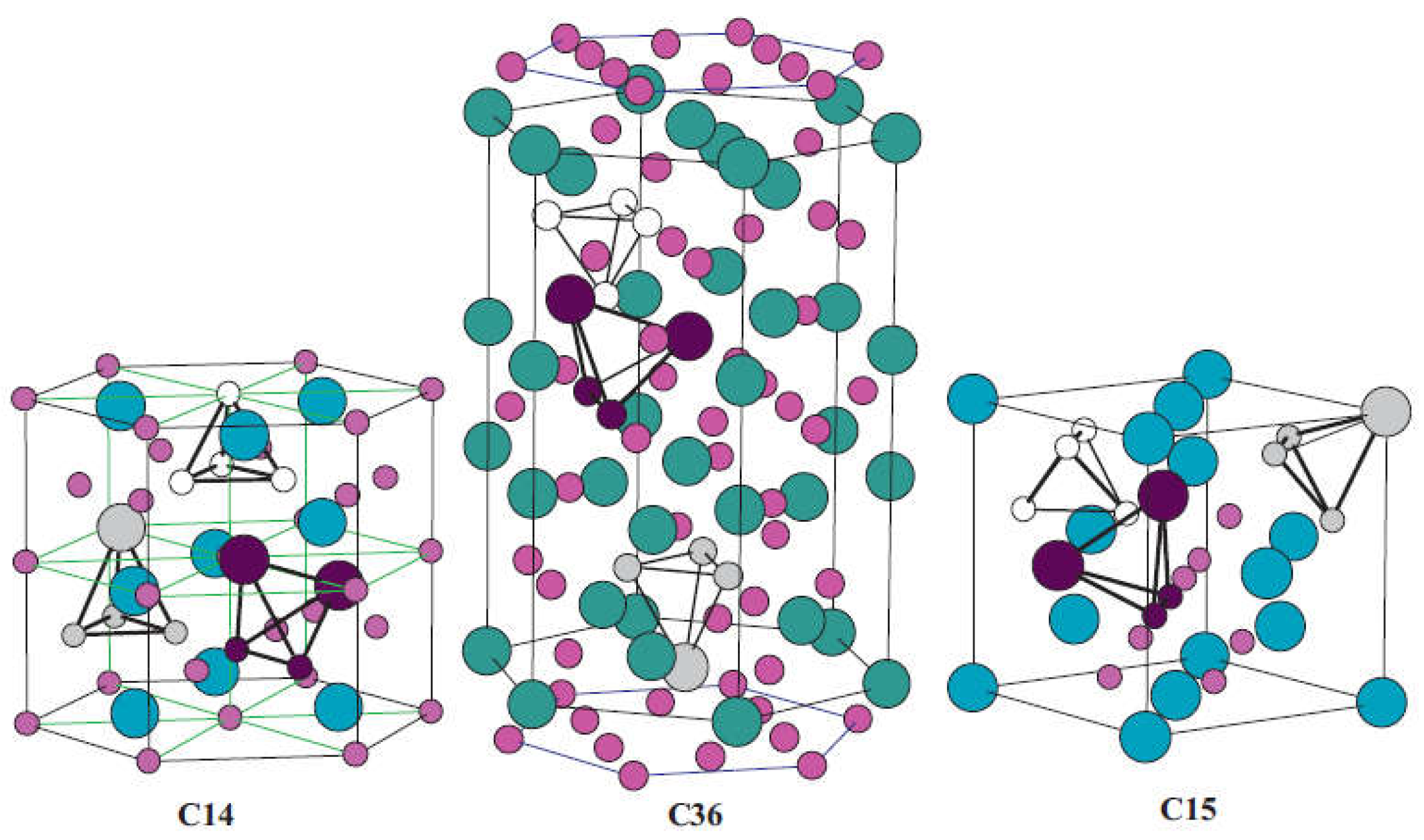
AB2-type Laves phase alloys represent one of the most promising materials categories for high-pressure MH tank application primarily because their high dissociation pressures [18,19,20,21]. High variety of itersititial sites endow them with abundant accommodation positions for hydrogen atoms, therefore they display prominent hydrogen storage properties like comparably high hydrogen capacity, excellent kinetics and favorable activation properties [22,23,24]. As shown in Figure 2, AB2-type Laves phase alloys possess one the following three structures types: hexagonal C14 (MgZn2-type), cubic C15 (MgCu2-type), and hexagonal C36 (MgNi2-type) [25]. There are three types of tetrahedral sites in these structures: A2B2, AB3 and B4. Regarding hydrogen absorption, these interstitial sites show distinct preferences in respect to the accommodation of hydrogen atoms [26]. Hydrogen atoms favor the A2B2 interstitial positions, followed by the AB3 sites, whereas the B4 sites are unable to provide accommodation for hydrogen atoms. Theoretically, the maximum capacity of C14-type and C15-type Laves phases can reach up to 6.3 and 6 hydrogen atoms per formula unit, respectively [27].

2.1.1. TiCr2-Based Alloys

The Ti-Cr system often shows significant deviation from the stoichiometric nominal TiCr2 alloy with a non-stoichiometric composition of TiCrx (1.6 ≤ x ≤ 2.2). The hexagonal C14 phase is a high-temperature structure, the cubic C15 phase is a low-temperature one, and the structural C36 polytype is an intermediate one with existing at temperatures between those of the C15 and C14 structure. Pioneering work carried out by Johnson and Reilly in 1978 when they found that the C15 phase TiCr1.8 can reversibly absorb hydrogen to form two nonstoichiometric phases, TiCr1.8H2.6 and TiCr1.8H3.6 at 195 K [28]. Both hydrides are extremely unstable possessing high dissociation pressures of 0.2 MPa and 5 MPa at 195 K, respectively. Subsequently, they investigated the reaction of C14 phase TiCr1.9 with hydrogen at the same conditions [29]. This phase can directly uptake hydrogen to produce two unstable nonstoichiometric hydrides of TiCrl.9H2.5 and TiCr1.9H3.5 having at 195 K having dissociation pressures of ~0.02 MPa and 3 MPa, respectively. Hydrogen absorption of C14 phase TiCr1.8 at the extremely high pressure of 200 MPa results in the formation of the hydrogen-rich phase TiCr1.8H4.5 (3.1 wt%) [30]. In comparison with C14 and C15, hydrides of the C36 phase are much more stable but the hydrogen capacities (TiCr2Hx, x ≤ 0.5) are too low to be regarded for hydrogen storage purposes [31,32,33].
For possible applications in high-pressure MH tank, the plateau pressures of C14 and C15 phases should be lowered meanwhile the hydrogen capacity under moderate pressures needs to be improved to meet the requirements. Partial element substitution at the A sites and/or the B sites has been proven to be an effective method to optimize hydrogen storage performances, like the plateau pressure, capacity, activation and the absorption/desorption hysteresis [34]. From first-principles calculations of C14-type Laves phase Ti-Mn hydrides, Nagasako et al. [35] concluded that the heat of formation (∆H) of transition metal hydrides can be predicted qualitatively by a single parameter, the B to V ratio, with B being the bulk modulus and V the equilibrium volume of the host alloy. This computationally motivated, yet empirical rule can be used to obtain an estimate for the dissociation pressure (P) given by lnP∝B/V to describe the metal hydride decomposition by hydrogen desorption [15]. The relationship found states that elements with small bulk modulus and/or large atomic radius can effectively lower the dissociation pressures of hydrogen storage alloys. The increase of lattice volume will presumably lead to the expansion of the interstitial sites, thus resulting in easier hydrogen uptake and higher hydrogen capacity, which may be an element of the underlying mechanism captured by the empirical rule [36]. In the wake of the publication of the empirical rule, many computational studies were conducted on TiCr2-based alloys including C15 structure [37], C14 Laves phase compounds TiX2 (X = Cr, Mn, Fe) [38] and TiCrMn [39], which provided useful guidelines to improve the efficiency for designing new TiCr2-based alloys.
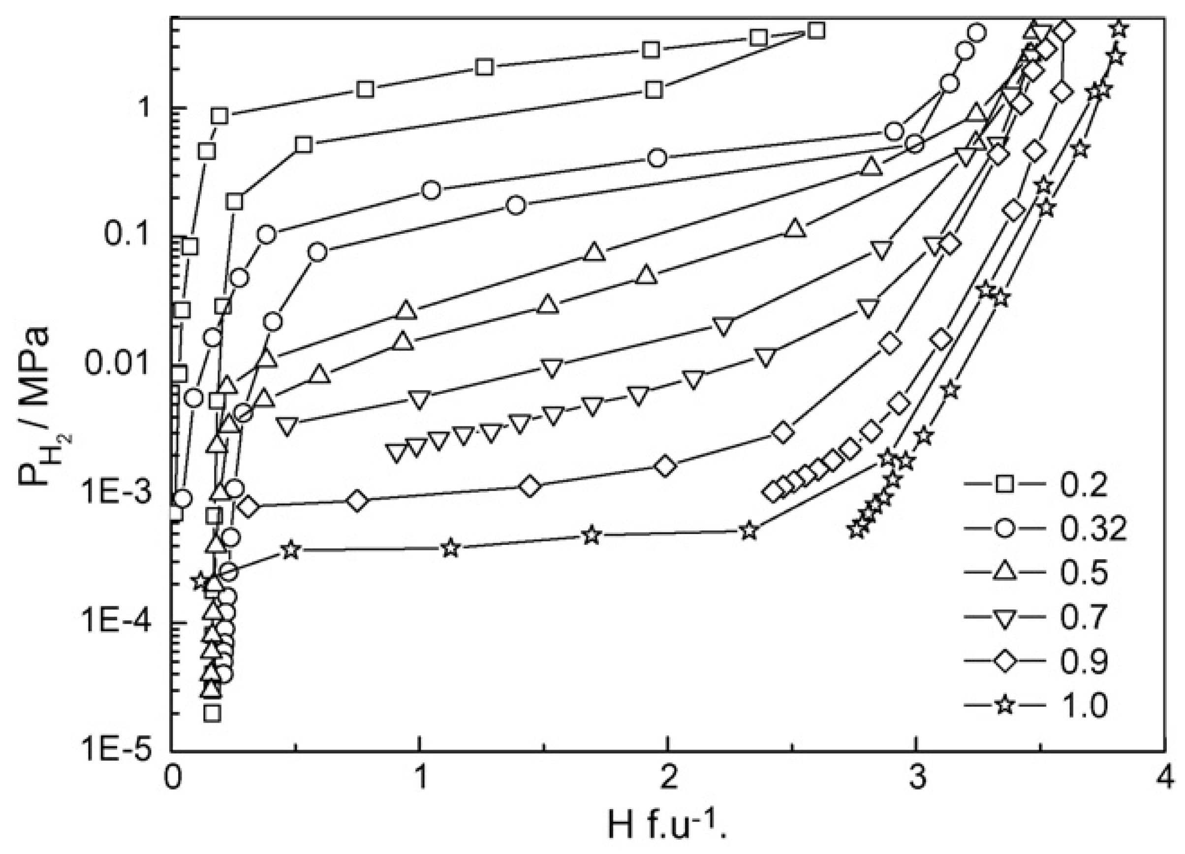
According to the computational and empirical rule, alloying elements such as Zr, Sc at the A site and Mn, V, Fe, etc. at B site, were chosen to optimize the performance of TiCr2-based alloys. Wu et al. [40,41,42] studied the influence of Zr and Sc on the hydrogen storage properties of TiMnCr. With the increase of the Zr content in Ti1-xZrxMnCr (x = 0~1.0), the average value of the hydrogen capacity increases linearly, the plateau pressure decreases monotonously, and the hysteresis between the absorption and desorption curves decreases as the x value increases from 0.2 to 0.32, but increases again as the x value is further raised [40]. When x lies at values between 0.2 and 0.32 in the alloys, the corresponding hydride displays a dissociation pressure higher than 0.1 MPa at 293 K (Figure 3). The introduction of Zr in Ti1-xZrx(Mn0.5Cr0.5)2 (x = 0, 0.1, 0.2, 0.32, 0.5) alloys induces the decrease of the equilibrium pressure and the increase of hydrogen capacity [41]. These two effects result in a maximum reversible capacity at x = 0.32, meanwhile the dissociation pressure exceeds 0.1 MPa at 293 K if x is less than 0.32 in the alloys. Similar to the effect of Zr, the increase of the Sc content in Ti1-xScxMnCr (x = 0.05, 0.10, 0.15, 0.22, 0.27 and 0.32) alloys also increases the hydrogen storage capacity and decreases the pressure of the absorption/desorption plateau [42]. The difference is that the Sc doped alloys suffer from much steeper plateaus than the Zr containing alloys. The partial substitution of the Cr by Mn alters the properties of both the parent alloys and their corresponding hydrides [43,44,45] in the following ways. The lattice contraction induced by Mn addition in TiCrMn makes the accommodation of a single H atom more difficult, and consequently this alloy exhibits a high desorption plateau pressure exceeding 10 MPa at 313 K [46]. P–C isotherms of TiCr2-xMnx–H2 (0 ≤ x ≤ 1) over a wide range of temperatures from 212 K to 433 K and pressures up to 100 MPa H2 indicate that both the low-composition hydride phases, i.e. x being small, TiB2H~3 (where B = Cr + Mn) and the high-composition hydride phase (TiB2H~4) , i.e. x being large, are unstable with equilibrium pressures over 1 MPa under ambient conditions [47]. The substitution of V for Cr leads to great changes in the structural and thermodynamic properties of TiCr2-xVx (0 ≤ x ≤ 1.2) compounds [48]. The TiCr2-xVx alloy crystallizes in a C14-Laves phase structure for 0 ≤ x ≤ 0.3. For compositions 0.3 ≤ x ≤ 0.6 it coexists with a cubic compound, and for 0.6 ≤ x ≤ 1.2 the alloy forms a single BCC structure. In respect to thermodynamic stability, the plateau pressure displays a linear decrease with the increase of the V content, and only the TiCr2-xVx–H2 (x < 0.6) system possesses a plateau pressure higher than 0.1 MPa at 298 K. Substitution of the expensive elements V and/or Ti by ferrovanadium (FeV) and/or Ti sponge (TiS) in Ti0.98Zr0.02V0.43Fe0.09Cr0.05Mn1.5 leads to the decrease of absorption capacity from 2.0 wt% to 1.7 wt%, while the desorption plateau pressure stays at the high level of 1.5 MPa at 298 K [49].
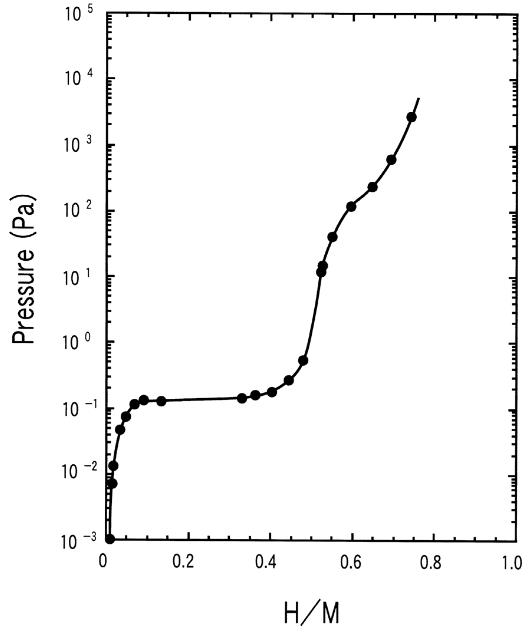
Compared with the stoichiometric AB2 alloys, mainly rich in A-atom (hypo or sub), have the same structure but display better hydrogen storage properties due to the high degree of disorder in the structures introduced by the presence of excess elements [50,51]. Hypo-stoichiometric AB2 alloys with increased Ti or Zr contents were investigated mainly because of their increased hydrogen uptake capacities [52,53,54], decreased plateau pressures [55,56], improved cycling performances [52], and improved low and/or high temperature properties [36]. For potentially unstable metal hydrides, Lee et al. [56] explored Ti-Zr-Cr-Mn Laves phase alloys by partial substitution of Zr for Ti and Cr, V, Cu for Mn to develop suitable materials with a plateau pressure less than 1 MPa at ambient temperature. Among them, (Ti0.75Zr0.25)1.05Mn0.8Cr1.05V0.05Cu0.1 was the best performing composition with a hydrogen capacity of 1.9 wt% and a desorption plateau pressure of 0.3 MPa at 303 K. In 2006, Kojima et al. [15] proposed the development of a Ti1.1CrMn alloy for the 33 MPa high-pressure MH tank for the first time. This non-stoichiometric alloy, having a dissociation pressure of 11 MPa at 296 K (Figure 4), can reversibly store 1.8 wt% H2 within 5 min in the pressure range of 33 and 0.1 MPa, meanwhile 94 % of the initial capacity can be retained even after 1000 cycles. Combining the hydrogen storage concepts of metal hydride and high pressure tank, by depositing 100 kg Ti1.1CrMn alloy in a 35 MPa tank of 100 L, in this way the created high-pressure hybrid tank provides 60 % more volumetric hydrogen density than the corresponding compressed hydrogen gas at the same conditions. For a hybrid system filled with 100 g of Ti1.1CrMn metal hydride, simulated results demonstrated that the filling process can be finished within less than 12 min at a pressure of 33 MPa [57]. Afterwards, a large variety of alloying elements were investigated to identify suitable non-stoichiometric compositions to fulfill the targets of high-pressure metal hydride MH tank applications. Substituting with Zr at the Ti sites in Ti1.1CrMn contributes to the improvement of hydrogen storage properties because of the larger radius and higher hydrogen affinity of Zr than of Ti [36]. The optimized (Ti0.9Zr0.1)1.1CrMn alloy enjoys an improved hydrogen capacity of 2.2 wt%, and the reversible absorption and desorption process can be accomplished within 4.2 min at 16 MPa even and a low temperature of 268 K. Based on the thermodynamic calculations, this optimized Zr substituted alloy desorbs hydrogen at 0.32 MPa at 303 K and 13.5 MPa at 353 K, which shows a significant reduction in the sorption pressure plateau compared to the Ti1.1CrMn alloy. Ouyang et al. [58] further optimized the hydrogen storage properties of Ti1.1CrMn through the partial substitution of Ti by Zr, and of Cr by Mo and W. According to their calculations, if a hybrid tank is filled with 28 % of (Ti0.85Zr0.15)1.1Cr0.9Mo0.1Mn, with a dissociation pressure of ~1 MPa and a capacity of and 1.78 wt% at 273 K, the volumetric hydrogen density of the tank system will reach 40 kg/m3, meanwhile the gravimetric density remains at the relatively high value of 2.72 wt%. Afterwards, they tried to employ Fe at the B site to lower the cost, and the corresponding (Ti0.85Zr0.15)1.1Cr0.925MnFe0.075 alloy displays a similar desorption plateau pressure of 1.06 MPa but a reduced hydrogen capacity of 1.54 wt% at 273 K [59]. Moreover, this alloy can finish the dehydrogenation process within 2 min at 298 K at an initial pressure of 0.1 MPa, and there is almost no capacity loss after 50 absorption/desorption cycles. Chen et al. [60] adjusted the ratio of Cr, Mn, and Fe elements in Ti-Cr-Mn-Fe based alloys to find an appropriate alloy for hybrid hydrogen storage tank. The results indicate that the increase of plateau pressures with the decrease of Fe and Mn content, respectively, as was shown for the two series of alloys TiCr1.9-xMn0.1Fex (0.4 ≤ x ≤ 0.6) and TiCr1.4-yMnyFe0.6 (0.1 ≤ y ≤ 0.3) alloys. Among these, the Ti super-stoichiometric Ti1.02Cr1.1Mn0.3Fe0.6 alloy showed the best overall hydrogen storage properties, delivering a hydrogen capacity of 1.78 wt% and a hydrogen desorption pressure plateau of 41.28 MPa at 318 K. The authors also found that the Ti super-stoichiometry can lead to the expansion of the unit cell, thus contributing to the improvement of hydrogen capacity as well as the decrease of plateau pressure in the Ti1+xCr1.2Mn0.2Fe0.6 (x = 0 ≤ x ≤ 0.1) alloys [61]. Annealing helps to increase the hydrogen absorption and desorption plateau pressure, and to flatten the hydrogen desorption plateau of the Ti1.02Cr1.1Mn0.3Fe0.6 alloy [62]. The annealed alloy displays a dissociation pressure of 45.12 MPa at 318 K and a hydrogen capacity of 1.721 wt%. Chen et al. also adopted rare earth elements (RE = La, Ce, Ho) to modify the original Ti1.02Cr1.1Mn0.3Fe0.6 alloy for improved hydrogen storage behavior. The applied rare earth metal substitutions helped to increase the hydrogen capacity, to lower the absorption/desorption plateau pressure, and to ameliorate the activation properties [63]. Among the studied alloys, the Ti1.02Cr1.1Mn0.3Fe0.6La0.03 alloy displays the best overall properties with a hydrogen absorption plateau pressure of 39.31 MPa and 51.27 MPa at 298 K and 318 K, respectively, and a hydrogen capacity up to 1.715 wt%. Li et al. [64,65,66] balanced the elemental contents of Ti, Cr, Fe and Mn to search for proper Ti-Cr-Fe-Mn based alloys for high pressure hydrogen storage. Based on their discoveries, the Ti1.05Cr0.75Fe0.25Mn1.0 alloy with a reversible hydrogen capacity of 1.55 wt% at 271 K and a desorption plateau pressure of 45 MPa at 333 K was applicable. The authors estimate that high pressure hybrid tank based on this material would provide a volumetric density higher than 40 kg/m3 while being able to supply hydrogen even at temperatures as low as 243 K [66]. Puszkiel et al. [67] designed a non-stoichiometric AB2 C14 Laves alloy (Ti0.9Zr0.1)1.25Cr0.85Mn1.1Mo0.05 for application in a hybrid reservoir. This alloy has proper thermodynamic stability (nearby 20 kJ/mol H2) with a desorption equilibrium pressure of 1.4 MPa at 273 K, a hydrogen capacity of 1.5 wt% as well as an absorption/desorption time of 25 s and 70 s, respectively. When the (Ti0.9Zr0.1)1.25Cr0.85Mn1.1Mo0.05 alloy and 10 wt% expanded natural graphite were employed, the hybrid system with a filling degree material of 60 % presents a hydrogen volumetric and gravimetric density of 19 kg H2/m3 and 1.8 wt% for the system at a hydrogen pressure of 25 MPa.

2.1.2. ZrFe2-based alloys

The Zr-Fe system forms several stoichiometric phases, of which the most important one in respect to hydrogen storage are so far the nominal ZrFe2 alloy displaying a cubic C15 Laves phase structure [68]. The hydrogen absorption capacity of the ZrFe2 alloy is less than 0.1 wt% under 6.2 MPa hydrogen at room temperature, hence it was not considered as a hydrogen absorber until a super high pressure of 1080 MPa was used for the hydrogenation process [69]. The desorption equilibrium pressure of ZrFe2H4 even reaches up to 34 MPa at room temperature [70,71]. The hydrogen capacity of ZrFe2 delivers a relatively high value of 1.7 wt% H2 at 180 MPa, and an absorption and desorption plateau pressures of 69 MPa and 32.5 MPa, respectively, at room temperature [69].
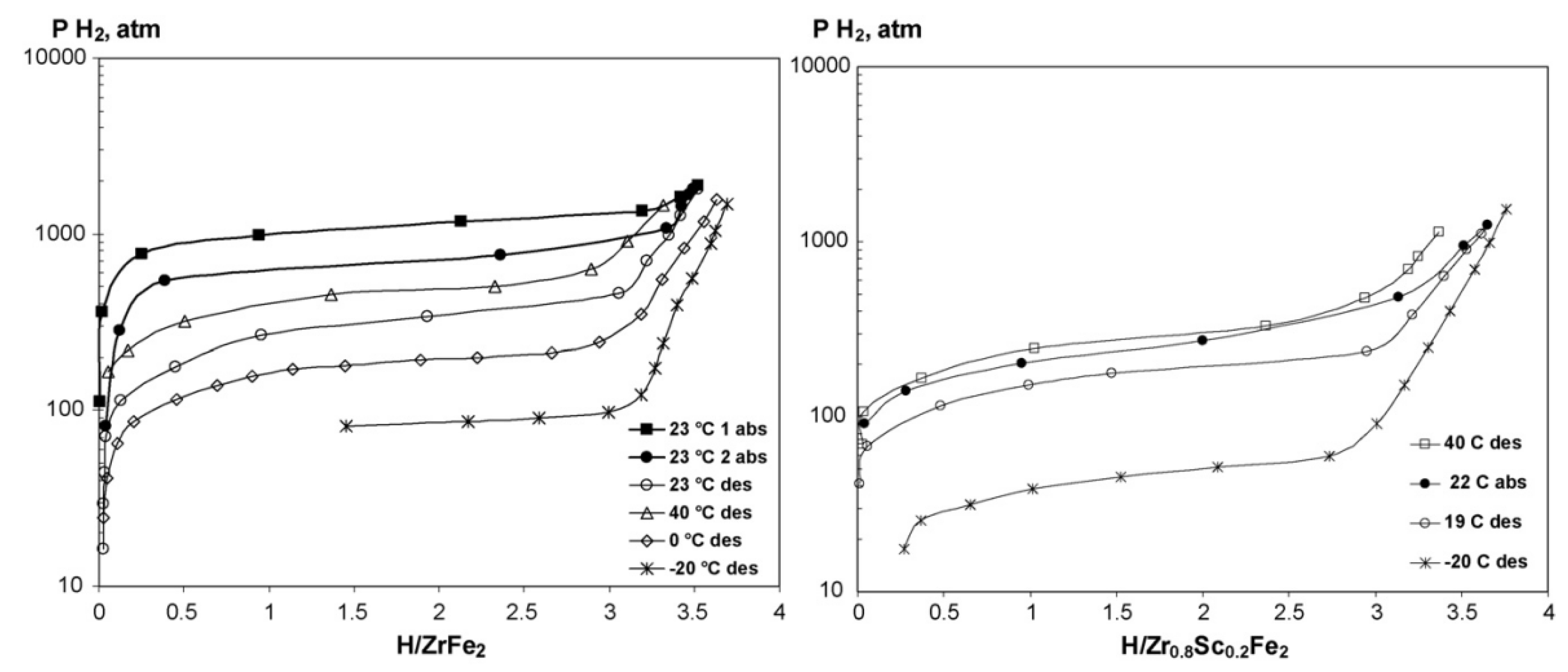
To improve the hydrogen storage properties of ZrFe2 derived alloys various alloying elements such as Sc, Ti at the A site and V, Cr, Mn, Ni, Al, Mo at the B site, were applied. As shown in Figure 5, substitution of Sc for Zr in ZrFe2 to generate Zr0.8Sc0.2Fe2 leads to the significant decrease of the desorption plateau pressure to 4.9 MPa at 253 K [69]. The Zr0.8Sc0.2Fe2 alloy can also react with hydrogen at 10 MPa even without any activation treatment at such a low temperature. Koultoukis et al. [72] substituted Fe with Cr or V in ZrFe2 producing the ZrFe1.8M0.2 (M = V, Cr) alloys to promote the application of metal hydride hydrogen compressor systems. Compared to Cr containing alloys, the V substituted samples show lower plateau pressure and less hysteresis, but still a similar maximum hydrogen capacity of 1.4 wt% at 293 K. With the increase of the Fe substitution by V in the alloy series ZrFe2-xVx (x = 0.2, 0.4, 0.6, 0.8), the plateau pressure significantly decreases and the stability of the hydrides increases, accompanied by a gradual transformation of the C15 lattice structure into the C14 structure [73]. The substitution of Mn at the Fe sites resulting in the series of ZrFe2−xMnx (x = 0.2, 0.4, 0.6, 0.8) increases the unit cell volume thereby lowering the plateau pressure and increasing the hydrogen storage capacity [74]. All these Mn substituted alloys form unstable hydrides with an equilibrium pressure surpassing 0.2 MPa at 303 K. The increase of the Ni content from 0.2 to 0.8 in ZrFe2−xNix (0.2 ≤ x ≤ 0.8) alloys at 295 K effectively reduces the dissociation pressure from 32.5 MPa to 11.5 MPa while essentially keeping the absorbed hydrogen capacity at values of 1.7–1.8 wt% at 295 K at 100 Mpa [75]. The formation of ZrFe1.8Ni0.2H3.5 and ZrFe1.2Ni0.8H3.7 hydrides results in isotropic expansion (24–26.5 %) of the metal lattice without changing the structure type and the hydrogen atoms tend to occupy the tetrahedral sites with the [Zr(Fe, Ni)3] coordination [76]. The substitution of Al for Fe in ZrFe2 alloy contributes to very fast H/D exchange kinetics in the formed hydrides accompanied by a dramatic decrease of the deuterium absorption plateau pressures [77]. When x increases from 0.02 to 0.04 in ZrFe2−xAlx alloys, the absorption plateau pressure at room temperature decreases from 56 MPa to 41 MPa [78]. Extensive studies have been devoted to Zr(Fe1-xMx)2 (M = V [79,80,81], Mn [82,83], Ni [84], Co [85], Al [86], Cr [87,88], etc.), ZrMnFex (x = 1.2-1.4) [89], Zr1-xTixMnFe (x = 0.2, 0.3) [90] alloys to improve hydrogen storage properties.
Compared with individual element substitution, multi-element substitution shows much more advantages in obtaining excellent hydrogen storage performances. Zotov et al. [91] found that Ti and Al substitution effectively lower the hydrogen absorption plateau pressure to 3.4 MPa for the composition of Zr0.5Ti0.5Fe1.6Al0.4 at room temperature. Subsequently through multiple elements substitution at both the A and B sites, they flexibly adjusted the absorption/desorption plateau pressures of Zr1-xM1x(Fe1-yM2y)2 (M1 = Ti, Y, Dy; M2 = V, Cr, Mn, Ni, Co, Cu and Mo) alloys in the range from 0.5 MPa to 250 MPa [92]. The mischmetal (Mm), Ti and Cr substituted Zr1-2xMmxTixFe1.4Cr0.6 (x = 0, 0.05, 0.1 and 0.2) alloys show high hydrogen capacity of ~1.75 wt% and kinetics of ~30 cm3 min-1 g-1, which is three times faster than the ZrFe1.4Cr0.6 alloy [93]. After annealing at 1270 K for 100 h, these alloys exhibit higher uptake of hydrogen and flatter absorption/desorption plateau than before the treatment [94]. The optimal composition Zr0.9Mm0.05Ti0.05Fe1.4Cr0.6 possesses a relatively high storage capacity of ~1.94 wt% and a desorption plateau pressure of ~0.15 MPa at 299 K.
The non-stoichiometric compositions are also designed to improve the hydrogen storage properties of ZrFe2-based alloys. Sivov et al. [95] showed that the absorption/desorption plateau pressures of activated samples decrease considerably while the hysteresis between absorption and desorption isotherms increases with the decrease of the Fe content in ZrFex (1.9 ≤ x ≤ 2.5) alloys. Among them, ZrFe1.9 displays the best performance with a hydrogen capacity of 1.8 wt% and a dissociation pressure of 23.7 MPa at 295 K. In regard to substitutions of V for Fe in ZrFe2.05-xVx (0.05 ≤ x ≤ 0.2) alloys, Jiang et al. [96] found that the increase of the lattice parameters and the unit cell volumes of the alloys lead to the increase of hydrogen capacity, the decrease of plateau pressure, and to the decrease of the hysteresis factor. The dehydrogenation ∆RH of these alloys varies from 20.41 to 22.03 kJ/mol H2, and all their
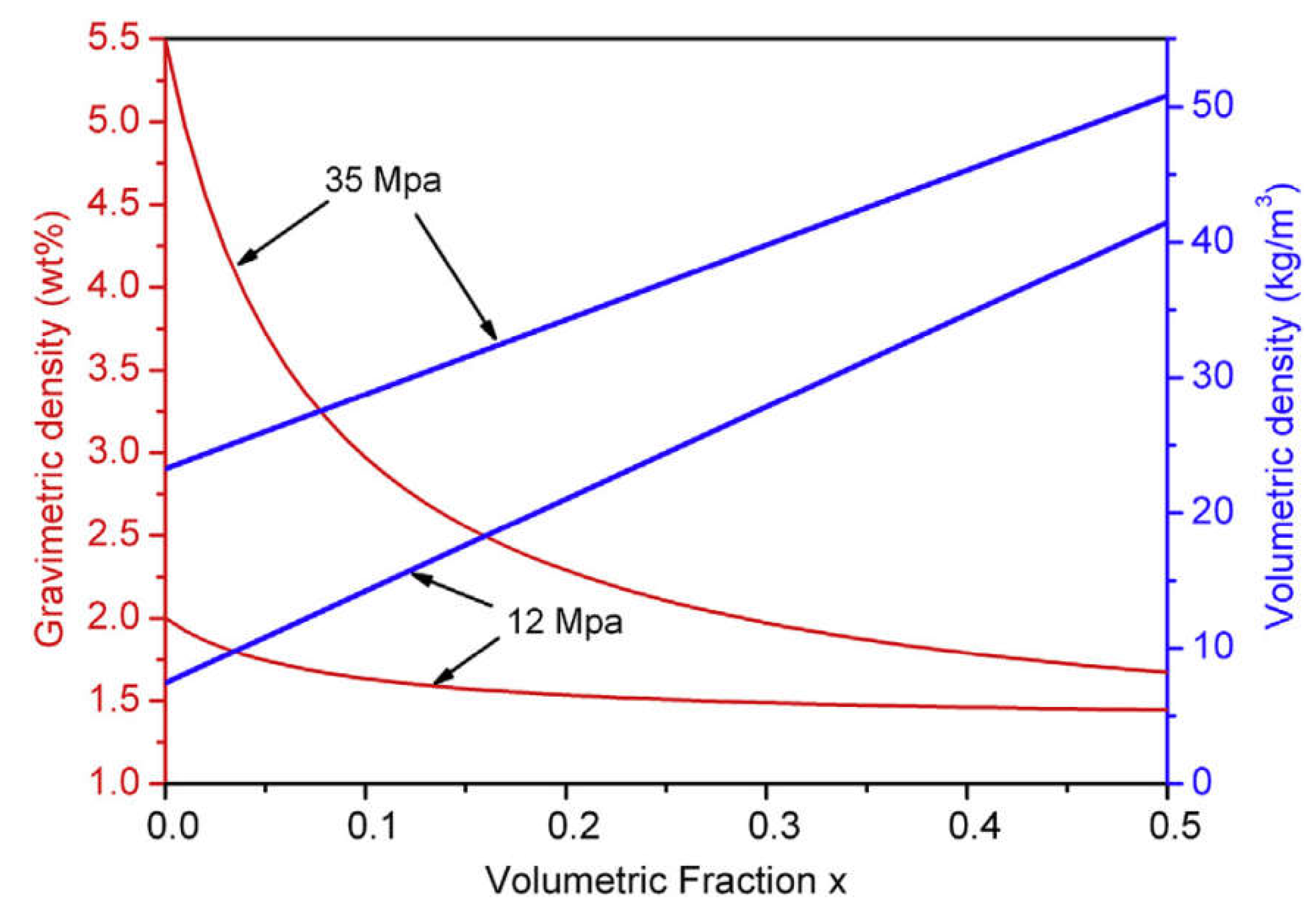
dissociation pressures are higher than 11 MPa at 313 K. For the possible use in high pressure metal hydride tank, Ouyang et al. [97] employed Ti and V to modify the properties of Zr-Fe-V alloys, among which the non-stoichiometric (Zr0.7Ti0.3)1.04Fe1.8V0.2 alloy shows the best performance with a desorption plateau pressure and a reversible capacity of 1.12 MPa and 1.51 wt%, respectively. Combining this alloy with a 35 MPa high pressure tank, as shown in figure 6, the hybrid system can provide a gravimetric density of 1.95 wt% and a volumetric H2 density of 40 kg/m3, respectively. Afterwards, they developed the series of Zr1.05Fe1.85Cr0.15-xVx (x = 0.05, 0.075, 0.1) alloys by Cr and V substitution [98]. The Zr1.05Fe1.85Cr0.075V0.075 alloy delivers a hydrogen capacity of 1.54 wt%, and an absorption and desorption plateau pressure of 1.4 MPa and 0.97 MPa, respectively, at 243 K. Further investigations on the Ti, Mn and V substituted Zr1.05Fe2 alloys found that the addition of V decreases the hysteresis, while Ti leads to a low plateau slope and a high plateau pressure [99]. Among these alloys, Zr1.05Fe1.6Mn0.4 shows a high desorption plateau pressure of 2.06 MPa at 298 K, while Zr1.05Fe1.7Mn0.2V0.1 has the lowest hysteresis. Besides, there are more non-stoichiometric ZrFe2-based alloys displaying high plateau pressures over 0.1 MPa and moderate hydrogen storage capacities at room temperature such as Zr0.9Ti0.1(Mn0.9V0.1)1.1Fe0.5Ni0.5 [100], ZrMn0.85-xFe1+x (x = 0, 0.2, 0.4) [101], (Zr0.9Ti0.1)1.1Mn0.9V0.1Fe0.5Co0.5 [102], etc.

2.2. Solid Solution Alloys

Vanadium-based solid solution alloys with body-centred cubic (BCC) structures are considered as candidates mainly because of their relatively wide compositional range and high hydrogen capacities up to ~ 4 wt% H2 [103]. For instance, the Ti40V40Cr10Mn10 BCC alloy can absorb an extreme high amount of hydrogen expressed by the gravimetric density value of 4.2 wt% at 293 K at 3 MPa [104]. The hydrogen storage capacity of Ti43.5V49Fe7.5 is 3.9 wt% at 253 K and 5 MPa [104,105]. As shown in Figure 7, these alloys usually show two plateau pressures [106]. The plateau pressure of the first one is extremely low, and only about half of the absorbed hydrogen can be released under moderate conditions.
Alloying with other transition elements, such as Ti, Cr, Mn, Al, Mo, etc., is still the most effective approach to lower the thermodynamic stability and to improve the capacity of the corresponding metal hydrides. By replaced Cr with Mn and/or Fe in Ti-Cr-V alloys, Yoo et al. [107] was able to increase the reversible hydrogen capacity to 2.5 wt% without significantly changing the plateau pressure, and the available hydrogen. The Ti0.32Cr0.32V0.25Fe0.03Mn0.08 alloy reaches a high capacity value of 2.71 wt% with a desorption plateau pressure higher than 0.1 MPa at 313 K. The homogeneity of Ti–Cr–V alloys highly influences the hydrogen absorbing properties and the reversible hydrogen capacity of Ti1Cr1V1 alloy increases from 2.1 wt% to 2.7 wt% at 323 K and at 4 MPa after heat treatment [108]. RE (RE = La, Pr, Ce and Nd) addition can make H atoms entry into the V55Ti22.5Cr16.1Fe6.4 alloy derivatives easier by providing more diffusion pathways, thus greatly increases their absorption kinetics [109], while the addition of RE elements has little influence on their plateau pressures. These alloys have desorption plateau pressures around 0.1 MPa at room temperature, which is slightly higher or lower than that of the pristine alloy. Extensive efforts have been devoted to optimizing the hydrogen storage properties of vanadium based BCC alloys. Binary alloys such as V-Ti [110,111,112], V-Cr [113,114,115], and V-Mo [116,117,118], ternary alloys such as Ti-V-Cr [119,120,121], V-Ti-Fe [122,123,124], and multiternary systems including Ti-Cr-V-Mo [125], Ti-V-Fe-Cr [126], Ti-V-Cr-Fe-Al [127] were developed to yield less stable hydrides.
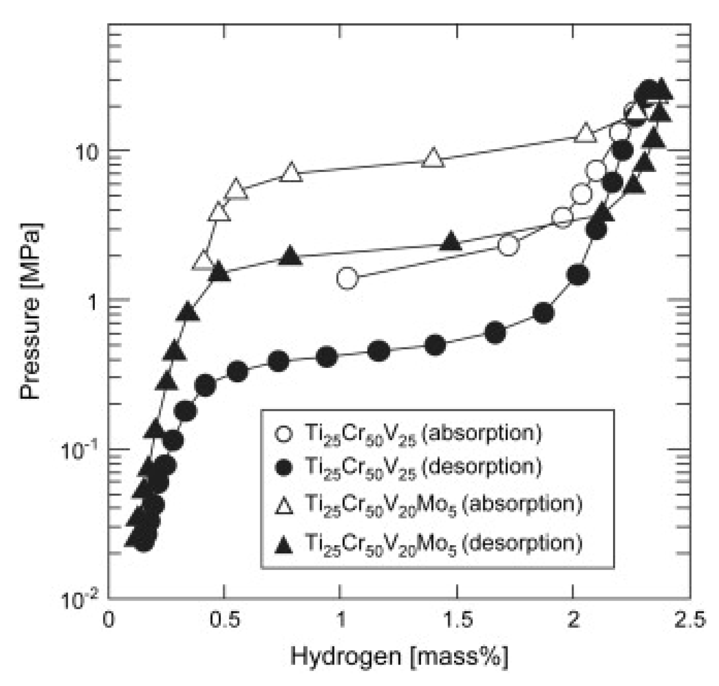
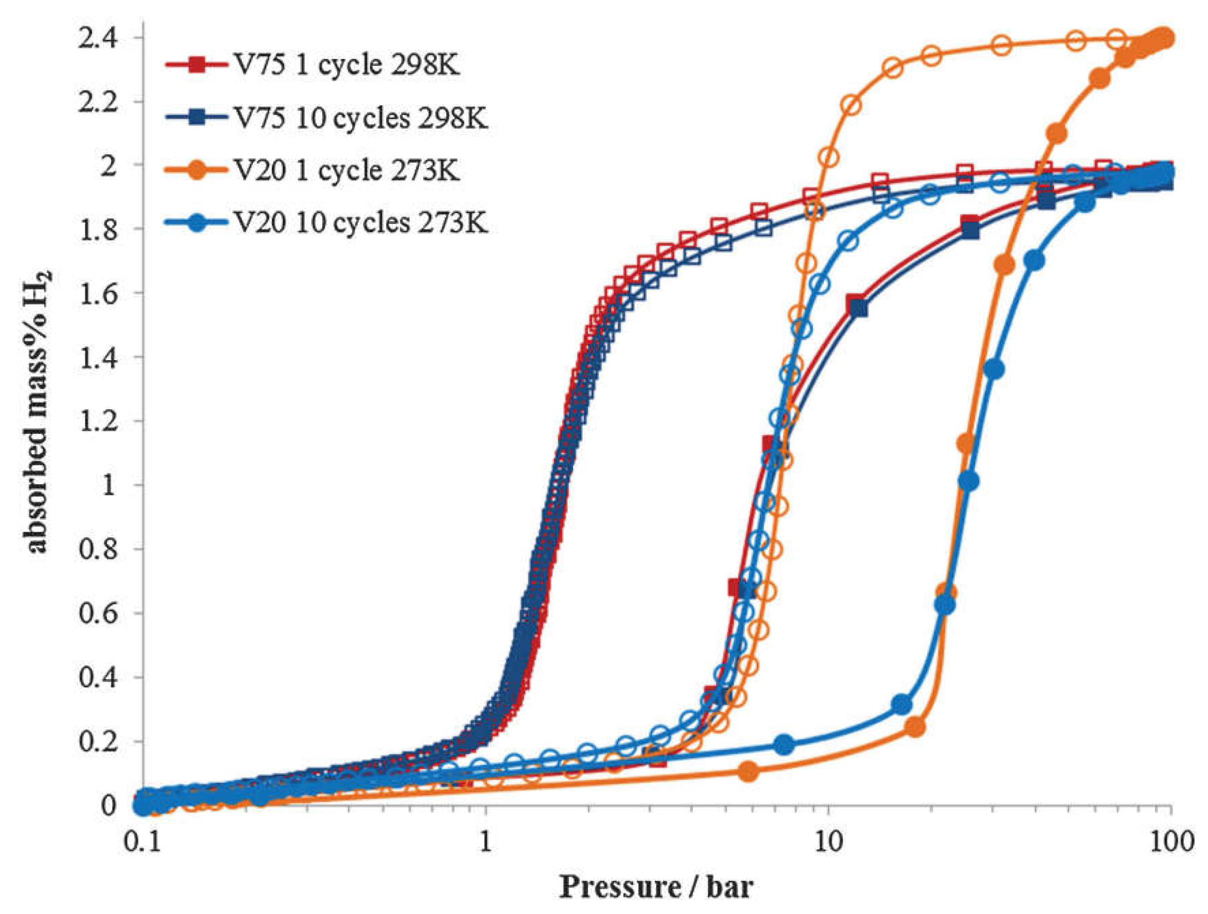
Although alloying with other transition elements effectively lowers the thermodynamic stability, the plateau pressures of most vanadium-based BCC alloys do not fulfill the requirements for high-pressure MH tank. Matsunaga et al. [16] tried to employ Mo possessing a large bulk modulus (272.5 GPa) to increase the plateau pressure of TiCrV based alloys. As shown in Figure 8, the Ti25Cr50V20Mo5 BCC alloy as an example of this effort enjoys an effective capacity of 2.4 wt% H2 between 0.1 MPa and 33 MPa at 298 K accompanied by a plateau pressure of 2.3 MPa at 298 K. The results turn out that elements with large bulk modulus such as Cr (190.1 GPa), Mo (272.5 GPa), and W (323.2 GPa) exert an effect to increase the plateau pressure of metal hydrides, which can help to design new materials with moderate stability. As shown in Figure 9, the composition of Ti-Cr-V-Mo alloys greatly influences their hydrogen storage properties [125]. Ti25Cr50V20Mo5 shows a higher capacity of ~2.4 wt% and a higher desorption plateau pressure of ~0.7 MPa at 273 K, while suffers from significant capacity degradation over 10 cycles. Ti10Cr10V75Mo5 has a slightly lower capacity of ~2.0 wt%,
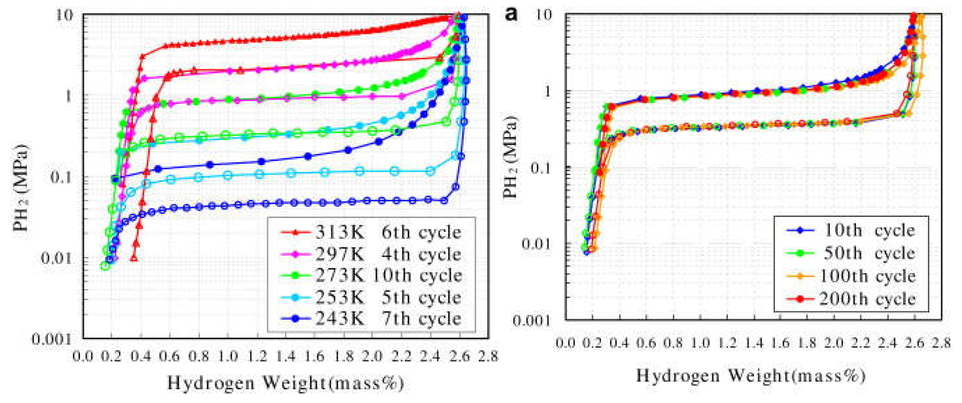
a significantly lower desorption plateau pressure of ~0.2 MPa at 298 K, but maintains good cycling stability. Further improvements of hydrogen properties of V-Ti-Cr alloys for high-pressure MH tank can be achieved through the composition optimization. Kuriiwa et al. [128] revealed that not only Ti/Cr ratio but also V content influences the hydrogen capacity, plateau pressure and cyclic durability. As shown in Figure 10, the 75at%V-5at%Ti-Cr alloy demonstrates a good flat hydrogen desorption plateau with a pressure of 0.35 MPa at 273 K, a reversible hydrogen capacity of 2.3 wt% at 10th cycle, and shows almost no degradation after 200 cycles. PC isotherms up to 100 MPa within the temperatures range from 273 K to 473 K reveal that 40V-20Ti-40Cr (at%) alloy has a reversible hydrogen capacity of 1.8 wt% and a desorption plateau pressure of ~0.25 MPa at 293 K [129]. During the first 10 absorption/desorption cycles, the V40Ti21.5Cr38.5 alloy experiences an obvious decay in the maximum capacity from 2.44 wt% to 1.88 wt% and the desorption plateau shifts to 0.25 MPa while the PC isotherms after 10 cycles are quite similar to those after 100 cycles [130]. There are more developed vanadium-based BCC alloys having the possibility for use in the hybrid system, as reviewed in references [131,132,133]. It should be noted that the high cost of V can be obstacle for large-scale applications [134]. Therefore, some cheaper V resources such as conventional ferrovanadium master alloy (FeV80) have been tested for the substitution of pure V. Nomura et al. [105] firstly tried to prepare Ti-V-X (X = Fe, Co, Ni, Cr and Pd) alloys using two kinds of industrial ferrovanadium alloys containing about 4 wt% of impurities (A1, Si, etc.), but remarkable differences in the PC isotherms were observed between the pure alloys with the impurity containing ones. Afterwards, Bibienne et al. [135] found that the ferrovanadium substitution in Ti1.56V0.36Cr1.08 and Ti1.26V0.63Cr1.11 BCC alloys result in no obvious change of the lattice, the hydrogen capacities, heat of formation, as well as entropy. V30Ti32Cr32Fe6 alloy prepared from a FeV80 master alloy is able to uptake 3.76 wt% H2 at 298 K, desorb 2.35 wt% H2, and has a desorption plateau pressure of 0.13 MPa at 298 K [136]. Wu et al. [137] found that V60Ti(21.4+x)Cr(6.6-x)Fe12 (0 ≤ x ≤ 3) alloys can quickly absorb hydrogen up to 3.8 wt% H2 at 298 K without the activation treatment, and the V60Ti22.4Cr5.6Fe12 alloy shows the largest reversible capacity of 2.12 wt% H2 with a dissociation pressure of 0.062 MPa at room temperature [138,139]. Afterwards, they prepared two series of (FeV80)48Ti26+xCr26 (0 ≤ x ≤ 4) and (VFe)60(TiCrCo)40-xZrx (0 ≤ x ≤ 2) alloys using the FeV80 master alloy, and both alloys have an effective capacity ~2.0 wt% at 298 K, and excellent cycling properties. These works show promise to realize the large-scale production of low-cost and unstable V-based alloys for on-board applications.

3. Complex Hydrides

Alanates, borohydrides, and amides are known as complex hydrides and have been widely investigated during the past decades mainly because of their high gravimetric densities [140]. For on-board applications, however, they suffer from severe thermodynamic and/or kinetic barriers in dehydrogenation and/or rehydrogenation. The pioneering work by Bogdanović et al. [141] indicated that catalysts doping, especially for titanium based species, enables the reversible hydrogen storage of NaAlH4 under moderate conditions by alleviating the kinetic issues. Subsequently, substantial numbers of studies focus on the development of proper catalysts or approaches to ameliorate thermodynamics or kinetics of the complex hydrides [142].

3.1. Transition Metal Alanates

Alkali metal and alkaline-earth metal alanates such as LiAlH4 (10.5 wt%), NaAlH4 (7.4 wt%), Mg(AlH4)2 (9.3 wt%), etc., offer high hydrogen capacities, but they usually suffer from high dehydrogenation temperatures and sluggish dehydrogenation kinetics. Transition metal alanates, in contrast, are usually thermodynamically less stable in respect to dehydrogenation, which leads to great difficulty in their synthesis. Some have even been theoretically discussed only [142].

3.1.1. Overview of Known Transition Metal Alanates

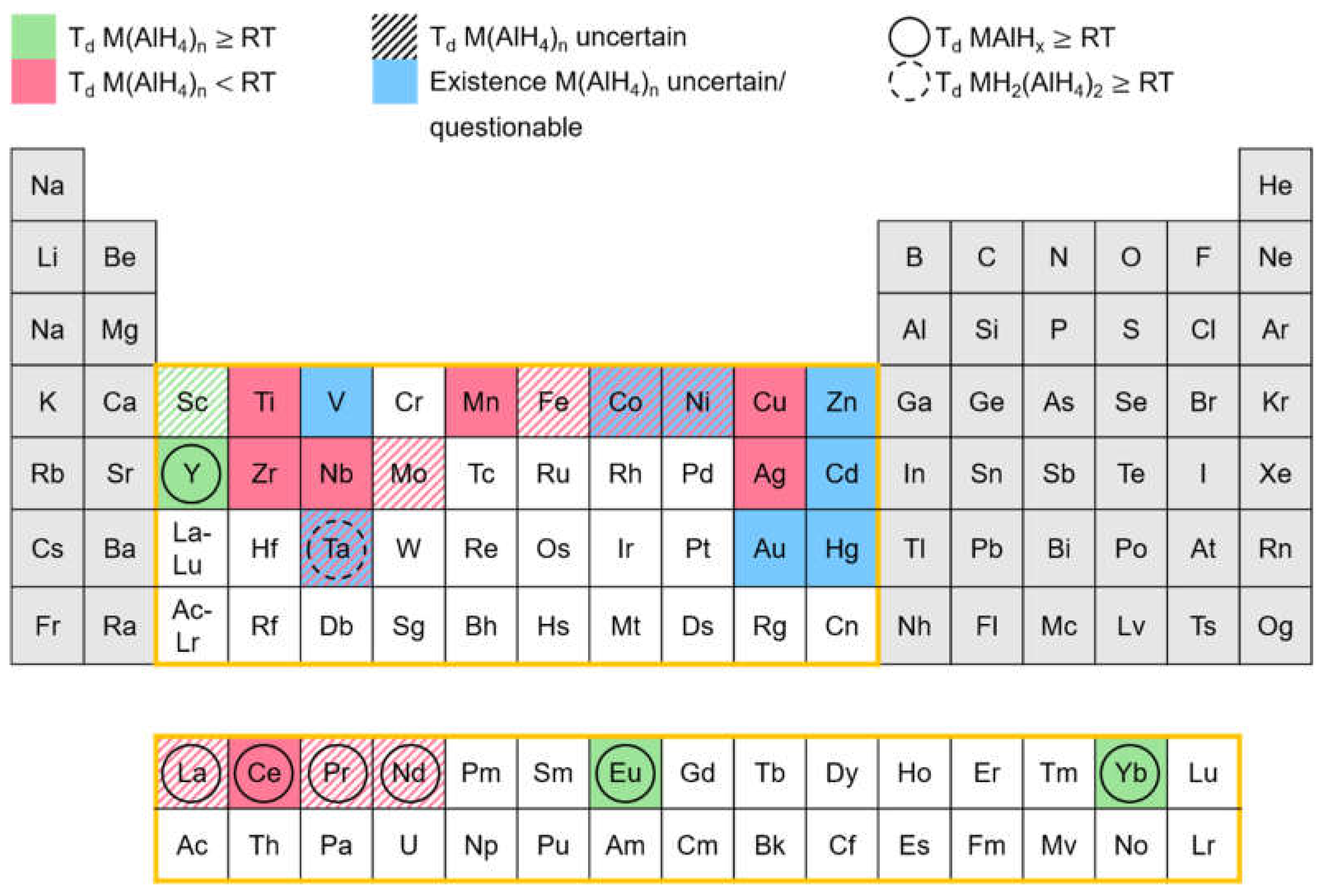
Since the early 1950s, a number of transition metal alanates have been synthesized. In order to give an overview of those alanates and their respective stability, Figure 11 was created.
The elements of the periodic table, marked in red, represent alanates which are reported to decompose below room temperature. Alanates, of the elements, marked in green, begin to decompose at room temperature or higher temperatures. Blue marked elements depict alanates, whose existence is indicated in the literature but is still uncertain and/or questionable. If the marking is hatched, the literature reports regarding the decomposition temperature are unclear or inconsistent.
Inconsistent literature reports are on hand for Fe(AlH4)2. Monnier observed decomposition at -125 °C [143], Kost and Golovanova at -70 °C [144], and Neumaier et al. [145] report it to be stable at room temperature. Unfortunately, Monnier does not specify the observations made during the decomposition process. If only hydrogen was being released, it could be explained by the reduction of Fe(III) to Fe(II) as FeCl3 was used as an reactant [146]. However, this does not explain the discrepancy between the statements of Kost and Golovanova [144], and Neumaier et al. [145].
According to Monnier, Co(AlH4)2 and Ni(AlH4)2 already decompose at -125 °C, the freezing point of the solvent diethyl ether [143]. The synthesis was presumably performed by freezing the reaction solutions layer wise and beginning the reaction by allowing the layers to melt. Therefore, it seems likely that the actual decomposition temperatures are much lower than the reported values. Consequently, the question arises whether Co(AlH4)2 and Ni(AlH4)2 can actually by synthesized.
While the existence of Sc(AlH4)3 and Mo(AlH4)5 is not in doubt, their decomposition temperatures are uncertain based on the literature. Sc(AlH4)3 was synthesized by Kuznetsov [147] only in form of the solvent adduct Sc(AlH4)3 Et2O. The decomposition temperature of this adduct (80 °C) suggests a decomposition temperature higher than room temperature for the alanate itself. Since the loss of solvent occurs simultaneously with the beginning of the dehydrogenation [147], the decomposition temperature of the alanate should be expected around 80 °C. Regarding Mo(AlH4)5, Monnier only states a slow decomposition at room temperature [143]. No further specification of the decomposition temperature was given. In Ref. [143], the decomposition of Mn(AlH4)2 is described in the same manner but Monnier specifies the decomposition temperature of Mn(AlH4)2 in another reference to be -25 °C [148], which is much lower than in Ref. [142]. This result combined with the overall instability of transition metal alanates indicates that the same might be true for Mo(AlH4)5.
In the case of the rare earth elements La, Pr, and Nd, the decomposition temperature of the respective alanate RE(AlH4)3 is uncertain because their synthesis was not yet successful. The synthesis was only attempted by Weidenthaler et al. via ball milling [149]. Since the reaction conditions of the ball milling procedure are much more aggressive than those of the synthesis in solution, it does not seem surprising that the likely unstable alanates RE(AlH4)3 could not be obtained. Instead the decomposition products REAlH6 were synthesized [149]. However, Ce(AlH4)3 could be synthesized in solution and has a decomposition temperature of -15 °C [148]. The decomposition temperatures and behavior of CeAlH6 and REAlH6 (RE= La, Pr, Nd) are very similar [149]. Presumably this similarity is not exclusive to the decomposition products MAlH6, but also includes the alanates RE(AlH4)3. Thus, for RE(AlH4)3 a decomposition temperature around -15 °C can be expected.
Attempts to synthesize V(AlH4)3, Ta(AlH4)n, Zn(AlH4)2, Cd(AlH4)2, Hg(AlH4)2, and Au(AlH4)3 were not successful. Even at temperatures as low as -135 °C (Hg [150]), -120 °C (Au [151]), and -80 °C (Cd [152], Ta [153], V [154], Zn [155]) the respective alanates were not obtained. Only the decomposition products in form of the hydrides (Hg [150], Cd [148,152], Zn [155]), the elements (Au [151]), or TaHn-m(AlH4)5-n [153,156] could be found. Hence the existence of these alanates themselves could not be demonstrated and therefore is deemed to be questionable.

3.1.2. Synthesis

Most of the transition metal alanates reported in the literature were first synthesized in solution in the 1950s to 1970s. In the 2010s the field of transition metal alanates was revived as new and already known alanates were prepared mechanochemically by ball milling.
Both approaches are usually carried out via a metathesis reaction (R1). The most commonly used reactants are LiAlH4 or NaAlH4 and the respective transition metal halide (MHalx). Transition metal perchlorates [157,158] and boronates [159] can also be employed as starting materials. Since transition metal alanates are sensitive to air and moisture, the synthesis must be performed under inert conditions. [142]
MHalx + n LiAlH4 → M(AlH4)n + n LiHal (R 1)
NaAlH4 NaHal
For the synthesis in solution ethereal solvents as diethyl ether and tetrahydrofuran are used. On account of the instability of most transition metal alanates, the synthesis in solution is usually performed at temperatures between -110 °C and -80 °C [160]. The advantages of the synthesis in solution over the mechanochemical approach are the milder reaction conditions and the possibility of preparing pure alanates. Because of the mild reaction conditions, the synthesis in solution is applicable to all transition metal alanates independently of their stability. The use of transition metal bromides and LiAlH4 allows the synthesis of pure alanates as the transition metal alanates are insoluble and the by-product LiBr is highly soluble in ethereal solutions [160].
Although the formation of a stable solvent adduct was only reported for Sc(AlH4)3 [147], it seems likely that other transition metal alanates form solvent adducts, too. This tendency towards adduct formation could hinder the preparation of pure, solvent free alanates and should be taken into consideration. The missing reports on solvent adducts can be explained by the largely insufficient characterization of the alanates in the 1950s to 1970s. In consequence of the instability of most transition metal alanates, the characterization often only involved the volumetric measurement of the hydrogen released during the decomposition, elemental analysis of the decomposed alanate, and possibly IR spectroscopy, XRD or DTA. These characterization techniques would not necessarily allow the determination of solvent adducts.
The mechanochemical approach by ball milling was only used for alanates stable above room temperature until now. It only allows the synthesis of a mixture of the transition metal alanate and the respective by-product, if the use of solvents is avoided.
Table 1. further summarizes the information given in the literature on transition metal alanates. Since the existence of Au(AlH4)3, Cd(AlH4)2, Co(AlH4)2, Hg(AlH4)2, Ni(AlH4)2, Ta(AlH4)n, V(AlH4)3 and Zn(AlH4)2 is in doubt and La(AlH4)3, Nd(AlH4)3, Pr(AlH4)3, and V(AlH4)3 have not yet been synthesized, they are not included in Table 1.Data of the known transition metal alanates - their hydrogen capacity (wt% H), decomposition temperature (Tdec), synthesis procedure, and the characterization techniques used. The hydrogen capacity corresponds to the pure alanates. The abbreviation EA stands for elemental analysis and the abbreviation VDH for volumetric determination of hydrogen released during the decomposition of the alanate.
Alanate wt% H Td (°C) Synthesis Characterization techniques Ref
Starting materials procedure
AgAlH4 2.9 -50 AgClO4, LiAlH4[157] in solution (diethyl ether) conductometric titration [157]
VDH [158]
[157,158]
Ce(AlH4)3 5.2 -15 Li3CeBr6, LiAlH4 in solution (diethyl ether) VDH, EA [148]
CeAlH6 3.5 100 CeCl3, NaAlH4 high energy ball milling under 1-15 bar hydrogen DSC, Thermolysis, XRD [149]
CuAlH4 4.3 ≤-80 [148] CuI, LiAlH4 [161,162]
Li2CuBr4, LiAlH4 [148]
in solution (tetrahydrofuran [161], diethyl ether [148,162]) VDH, EA [148,161,162]
IR [161,162]
[148,161,162]
Eu(AlH4)2 3.8 100 EuCl2, NaAlH4 high energy ball milling under 1-15 bar hydrogen, no separate preparation of EuAlH5 DSC, Thermolysis, XRD [163]
EuAlH5 2.7 180
Fe(AlH4)2 6.8 -125 [143]
-70 [144]
<RT [145]
FeCl3, LiAlH4 [145,146,164]
Li2FeBr4, LiAlH4 [148]
in solution (diethyl ether) VDH, EA [144,145,146]
IR [144]
Thermolysis [145]
DTA (not shown), XRD [146]
[143,144,145,146,148,164]
LaAlH6 3.5 100 LaCl3, NaAlH4 high energy ball milling under 1-15 bar hydrogen DSC, Thermolysis, XRD, 27Al-NMR [149]
Mn(AlH4)2 6.9 -20 Li2MnBr4, LiAlH4 in solution (diethyl ether) VDH, EA [148]
Mo(AlH4)5 8.0 ≤RT no information in solution (diethyl ether) no information stated [143]
Nb2(AlH4)5 5.9 0 [165]
>20 [166]
NbCl5, LiAlH4 in solution (diethyl ether) VDH, EA
Thermolysis, DTA (not shown), XRD, IR [165]
[144,153,165,166]
Nb2(AlH4)6 6.5 -50 [165]
-40<Td<20 [166]
VDH, EA
Nb2(AlH4)7 7.0 -90 [165]
-70<Td<-40 [166]
NdAlH6 3.4 100 NdCl3, NaAlH4 high energy ball milling under 1-15 bar hydrogen DSC, Thermolysis, XRD [149]
PrAlH6 3.5 100 PrCl3, NaAlH4 high energy ball milling under 1-15 bar hydrogen DSC, Thermolysis, XRD [149]
Sc(AlH4)3 Et2O 8.8 80 ScBr3, LiAlH4 in solution (diethyl ether) VDH, EA, IR, XRD, DTA, DTGA, MS [147]
TaH2(AlH4)2 4.1 60 [153]
130 [156]
TaCl5, LiAlH4 [153] TaBr5/TaCl5, LiAlH4 [156] in solution (diethyl ether) VDH, EA
Thermolysis [153,156]
XRD, IR, RAMAN [156]
[153,156]
Ti(AlH4)4 9.4 -70 [146]
-85 [167]
TiBr4/TiCl4, LiAlH4 [146]
TiCl4, LiAlH4 [167]
in solution (diethyl ether) VDH, EA
IR [144]
DTA (not shown), XRD [146]
[144,146,167]
Y(AlH4)3 6.7 50 [168]
80 [169]
YBr3, LiAlH4 [168]
YCl3, LiAlH4 [169]
in solution (diethyl ether) [168]
high energy ball milling under 80 bar hydrogen, no separate preparation of YAlH6 [169]
VDH, EA
IR, DTA (not shown) [168]
XRD, IR, TPD,MS, DSC, HP-DSC [169]
[168,169]
YAlH6 5.0 170 [169]
Yb(AlH4)2 3.4 70 YbBrx, LiAlH4 in solution (diethyl ether) VDH, EA, DTA (not shown), XRD, IR [144]
Yb(AlH4)3 4.6 100 YbCl3, LiAlH4 high energy ball milling under 100 bar hydrogen, no separate preparation of YbAlH6 XRD, IR, TGA-DSC-MS, HP-DSC [170]
YbAlH6 2.9 180
Zr(AlH4)4 7.5 <RT Zr(BH4)4, LiAlH4 in solution (diethyl ether) EA [159]

3.1.3. Dehydrogenation and Hydrogenation Behavior

The dehydrogenation and even more so the hydrogenation behavior of the transition metal alanates has not yet been investigated in great detail. This situation is mainly a consequence of the instability of the alanates.
Based on investigations on the decomposition behavior of the alanates by volumetric hydrogen and in some cases DTA measurements, Soloveichik [160] categorized four groups of decomposition mechanisms in 1983 (see R2-R5). The mechanism of Group III is a special case of Group II, in which the decomposition of AlH3 is catalyzed by the transition metal.
Mn(AlH4)n → Mn-m(AlH4)n-m + m AlH3 + 0.5 m H2 (R 2)
M(AlH4)n → M + n AlH3 + 0.5 n H2 (R 3)
M(AlH4)n → M + n Al + 2 n H2 (R 4)
M(AlH4)n → MHx(AlH4)n-x + n AlH3 (R 5)
Regarding the decomposition mechanisms gathered by Solveichik, it is notable that none of the decomposition mechanisms involve an intermediate of the form MxAlHy. This sort of intermediate was only known for CuAlH4 [161] in 1983. However, the existence of MxAlH6 was deemed to be an unique feature of CuAlH4 [160].
Nowadays it is assumed that the dehydrogenation of most alanates involves such intermediates [142]. Thus, this phenomenon needs to be taken into account and investigated in respect to transition metal alanates on a regular basis. More recent findings seem to support this hypothesis as well. Weidenthaler [149] was able to synthesize REAlH6 (RE = Ce, La, Nd, Pr), probably via unstable RE(AlH4)3 intermediates. Cao et al. could show a stepwise decomposition of Y(AlH4)3 [169] and Yb(AlH4)3 [170]. An intermediate formation of MAlH6 during the dehydrogenation processes was proposed. Unfortunately, the formation of MAlH6 could not be demonstrated beyond doubt. In the investigation of the thermal decomposition of Eu(AlH4)2 by Pommerin [163] an intermediate EuAlH5 was found.
The characterization of the dehydrogenation behavior of transition metal alanates remains incomplete and leaves much to be discovered in future investigations. These tasks include also the thermodynamics as only for REAlH6 (RE = Ce, La, Nd, Pr) a dehydrogenation enthalpy was reported [149]. The presented value of about 30 kJ/mol H2 is promising to obtain reversibility at benign conditions.
Successful rehydrogenation of a transition metal alanate was only achieved in the case of Y(AlH4)3 [169]. Here, the first dehydrogenation step is reversible at 145 °C and 100 bar. The reversible hydrogen storage capacity of around 2.5 wt% corresponds to 75 % of the theoretical storage capacity. It has to be noted, that a mixture of Y(AlH4)3 and LiCl was used for the investigation and not the pure alanate. However, this discovery holds promise for discovering new intermediate hydrides for low-temperature applications.

3.2. Transition Metal Boranates

Metal borohydrides M(BH4)n of alkali metals and alkaline earth metals raise great interest mainly because of their extremely high hydrogen densities often above 10 wt% (e.g. LiBH4 13.8 wt%, Mg(BH4)2 14.9 wt%). Their high decomposition temperatures and slow rehydrogenation kinetics demand tailoring before hydrogen storage applications are possible [171,172,173]. In contrast, transition metal boranates exhibit much lower decomposition temperatures while also maintaining high hydrogen densities. For instance, the onset decomposition temperature of Zr(BH4)4 (10.7 wt%) drops as low as 70-80 °C, which is much lower than that of M(BH4)n of alkali metals and alkaline earth metals (usually over 300 °C) [174].

3.2.1. Overview of Known Transition Metal Boranates

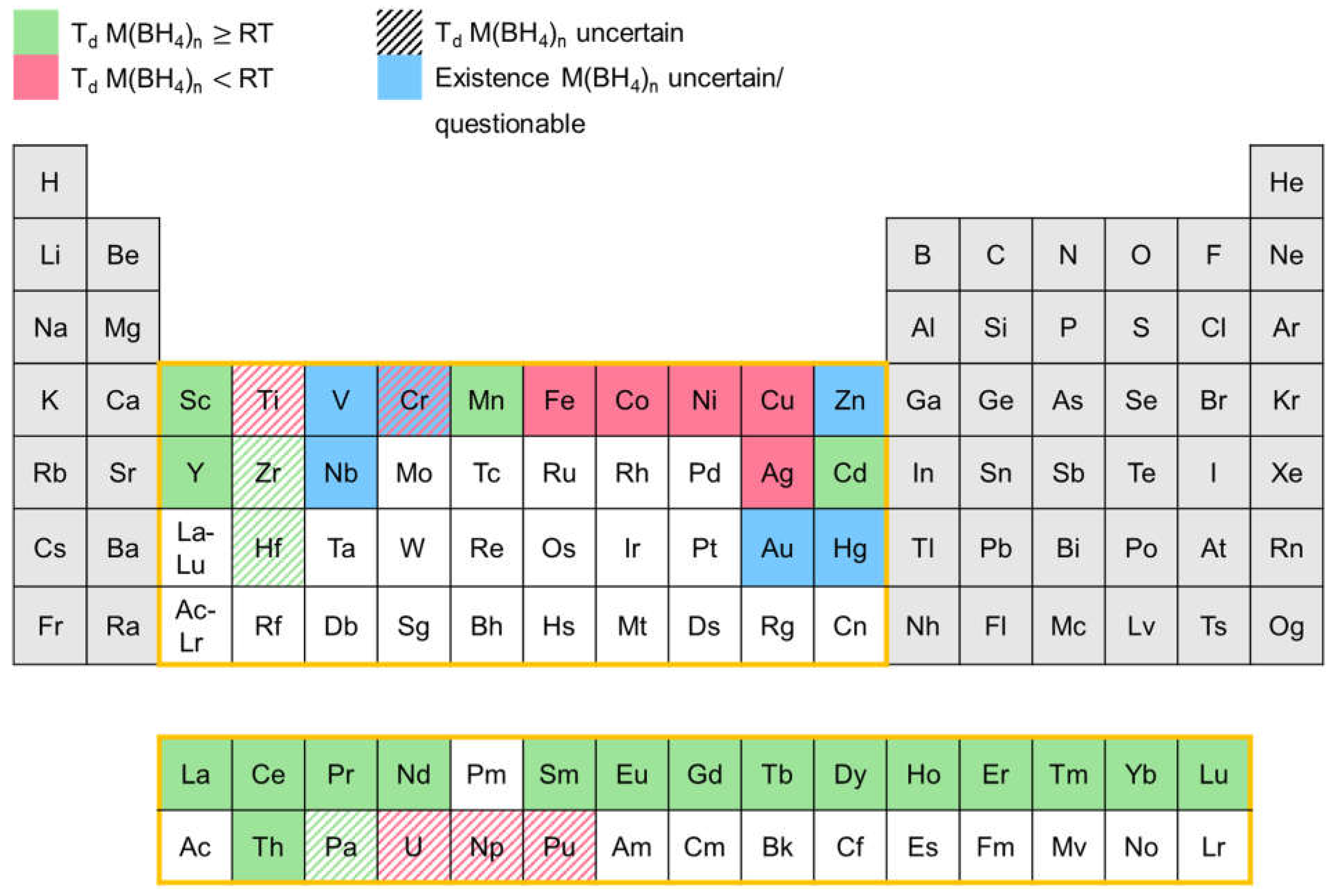
Since the 1940s a number of transition metal boranates were synthesized and characterized to some extent. In Figure 12 an overview of the transition metal boranates described in the literature up to now is presented. The elements in the periodic table marked in red represent corresponding boranates which are reported to decompose below room temperature. Boranates of the elements marked in green begin to decompose at room temperatures or above. Blue marked elements depict corresponding boranates whose existence is uncertain and/or questionable. Ruled markings indicate that the decomposition temperature is uncertain since conflicting information can be found in the literature.
The diagram shows that there is a correlation between the binary hydride gap and a low decomposition temperature of the corresponding transtion metal boranates. In general, elements having stable binary hydrides tend to form transition metal boranates with higher stability (decompose at room temperatures or above), while boranates of elements forming less stable or unstable binary hydrides like Fe, Co, Ni, etc, in most cases decompose below room temperature.
In the following, discrepancies in the published decomposition temperatures will be mainly discussed for the unstable borohydrides. The stable borohydrides and many solvent adducts (like those mentioned in Refs. [175,176,177,178]) are already described extensively in the review article by Suárez-Alcántara and García [174].
Nakamori et al. reported the synthesis of Cr(BH4)n, Ti(BH4)n, V(BH4)n, and Zn(BH4)2 (n=2-4) [179,180,181]. However, no clear evidence of their existence is presented as there are no B-H bands observable by Raman spectroscopy. Furthermore, no significant weight loss occurs in TG-MS measurements of Cr(BH4)n, Ti(BH4)n, V(BH4)n. In addition, the presented results are contradictory for the material obtained in the attempt to synthesize Ti(BH4)n since the evolution of hydrogen was observed in the corresponding TDS-GC experiment. Hence, we consider the synthesis of those boranates by Nakamori et al. as unsuccessfull. Because of the missing B-H bands in its Raman spectrum, the same is assumed for Zn(BH4)2 although a significant weight loss takes place in the TG-MS measurement and hydrogen evolution can be observed in the corresponding TDS-GC experiment.
The mechanochemical synthesis of Zn(BH4)2 was described by Joen et al. [182], Song et al. [183], and Srinivasan et al. [184] but Ravnsbaek et al. [185] and Gu et al. [186] were only able to obtain mixed cation zinc borohydrides via the more or less same ball milling procedure. Mikheeva et al. [187] observed mixed cation zinc borohydrides via a wet chemistry route, too. Consequently, the validity of the statements of the aforementioned groups can be doubted and the existence of Zn(BH4)2 remains unclear.
The reports on the decomposition temperature of vanadium(III) boranate are contradictory. Yang et al. [188] state that V(BH4)3 is stable up to 55 °C under 1 bar of hydrogen pressure, but Korablov et al. [189] claim to have found a vanadium boranate type which decomposes at about 190 °C but do not report an exact molecular formula for this compound. Based on the stoichiometries of the reactants, the formation of V(BH4)2 as well as V(BH4)3 would be possible. At the end, both research groups fail to deliver clear evidence of the successful synthesis of the respected boranate. Since hard evidence of the existence of the compound is missing, its existence needs to be considered as uncertain.
Suárez-Alcántara and García [174] assumed that niobium boranate exists and should be rather stable but the synthesis has not been attempted successfully yet.
For each of the following borohydrides Ti(BH4)3, Ce(BH4)3, Eu(BH4)n, Y(BH4)3, Yb(BH4)3, and Th(BH4)4 a relatively wide temperature range is reported for the decomposition temperature, that may result from the different synthesis strategies applied. For example, Park et al. mentioned differences in the decomposition temperatures of ball milled samples and those prepared from a gas solid reaction for Y(BH4)3 [190].
Attempts to synthesise AuBH4 [191] and Au(BH4)3 [151] were not successful at temperatures as low as -120 °C, which makes their existence questionable.

3.2.2. Synthesis

Most of the transition metal boranates reported in the literature, were first synthesized in ethereal solution under cooling with dry ice or liquid nitrogen. Since the 2000s a great interest in the field of transition metal boranates occured leading to an incrase in the work regarding the synthesis of already known and new boranates. Moreover, the mechanochemical approach was also established for the synthesis of boranates.
Both synthesis approaches are usually carried out via a metathesis reaction (R6). Since transition metal boranates are sensitive to air and moisture, the syntheses must be performed under inert conditions. [174] The most commonly used reactants are LiBH4 or NaBH4 and the respective transition metal halide (MHaln) [174]. In some cases [192], even transition metal perchlorates can be employed as starting materials. For volatile boranates such as Zr(BH4)4 and Hf(BH4)4 a solid state metathesis is also an option [193].
Another reaction pathway, often employed, is the reaction between transition metal hydrides and BH3-adducts in solvents such as dimethyl sulfide [194,195] or amines like triethyl amine [196,197] (R7). The reaction of the transition metal hydride with diborane (B2H6) is also applicable for the synthesis of boranates (R8) [190,198].
MHaln n LiBH4 → M(BH4)n + n LiHal (R 6)
NaBH4 NaHal
MHn
MHn
n Sol*BH3 → M(BH4)n + n Solv ( R 7)
0.5 n B2H6 → M(BH4)n ( R 8)
For the synthesis in solution, ethereal solvents such as diethyl ether, tetrahydrofuran, and dimethyl sulfide have been used. The advantages of the synthesis in solution over the mechanochemical approach are on the one hand the milder reaction conditions and on the other hand the prospect of being able to prepare pure boranates. Because of the differences in solubility of the transition metal boranates and the starting materials (LiBH4/NaBH4, MHaln) as well as the by-products (LiHal/NaHal), the separation of the boranate is possible. In this respect, solvent mixtures like dimethyl sulfide/toluene (20/80) can be benefical. While the boranate dissolves by forming a soluble solvent adduct with the dimethyl sulfide, the by-product (LiCl/NaCl) remains still insoluble. [194,199,200,201]
The transition metal boranate mixtures obtained in ball milling experiments can be purified by extraction with a solvent or solvent mixture [200,201].
Table 2 further summarizes the information given in the literature on transition metal boranates. Au(BH4)3, Cr(BH4)2, and V(BH4)3 are not included in this table since their existence is in doubt. It has to be mentioned, that the decomposition temperatures stated are obtained from the onset temperatures of the corresponding decomposition signals in the thermal measurements. If no value was found in the respective report, the onset temperature was determined by us from the shown graphs using the inflection tangent method [202].
Table 2. Data of the known transition metal boranates - their hydrogen capacity (wt% H), onset decomposition temperature (Tdec), synthesis procedure and techniques, used for their characterization. The hydrogen capacity corresponds to the pure boranate. The abbreviation EA stands for elemental analysis, VDH for volumetric determination of hydrogen released during the decomposition of the boranate, VPM for vapour pressure measurement, MP for magnetic properties and TPPA for temperature programmed photographic analysis.
Boranate wt% H Td (°C) Synthesis Characterization techniques Ref
Starting materials procedure
Ag(BH4) 3.28 -30 LiBH4, AgClO4 in solution (diethyl ether) VDH [192]
Ce(BH4)2 6.55 200-251 CeH3, S(CH3)2*BH3 [195]
LiBH4, CeCl3 [203,204,205]
in solution (dimethyl sulfide-toluene mixture [195], toluene [203])
extraction (dimethyl sulfide [203])
high energy ball milling [204,205]
in situ-XRD (synchrotron) [195,203], XRD [204,205], FT-IR [195,204,205], PCI [195], TG-DSC-MS [195,205], TG-DSC [203], DSC [204], MP [195] [195,203,204,205]
Co(BH4)2 9.10 -20 [206] CoCl2/CoLi2Br4, LiBH4 [206]
CoBr2, LiBH4 [207]
in solution (diethyl ether) EA [207] [206,207]
CuBH4 5.14 0 LiBH4, CuCl2 [208,209]
LiBH4,CuCl [210,211]
in solution (diethyl ether [208,209,210], THF/diethyl ether [211]) VDH, iodometric (Cu) [211] [208,209,210,211]
Cd(BH4)2 5,67 75 LiBH4, CdCl2 [212]
LiBH4/NaBH4/KBH4, CdCl2 [213]
high energy ball milling in situ-XRD (synchrotron) [213], XRD [212,213], PCI [212], MS [212], DSC [212], TG-DSC [213] [212,213]
Dy(BH4)3 5.84 250 DyH3, S(CH3)2*BH3 in solution (dimethyl sulfide-toluene mixture) in situ-XRD (synchrotron), FT-IR, PCI, TG-DSC-MS, MP [195]
Eu(BH4)2 4.44 290-395 EuH2, N(C2H5)2*BH3 [197]
EuH2, S(CH3)2*BH3 [195]
EuCl3, LiBH4 [214]
EuCl2, LiBH4 [214]
in solution (N(C2H5)2*BH3 [197], dimethyl sulfide-toluene mixture [195], diethyl ether [214])
extraction (dimethyl sulfide [214])
high energy ball milling [214]
annealing [214]
in situ-XRD (synchrotron) [195,197,214], XRD [197,214], FT-IR [195,197,214], Raman [197], PCI [195,214], TG-DSC-MS [195,214], DSC [197], MP [195] [195,197,214]
Eu(BH4)3 6.16 < 100 [215]
168 [216]
EuCl3, LiBH4 high energy ball milling in situ-XRD (synchrotron) [216], XRD [215,216], ATR/FT-IR [215,216], TG-DSC [215], TG-DSC-MS [216], SEM [215] [215,216]
Er(BH4)3 5.71 245-264 ErH3, S(CH3)2*BH3 [195]
ErCl3, LiBH4 [217,218]
ErCl3, NaBH4 [218]
in solution (dimethyl sulfide-toluene mixture [195])
extraction (dimethyl sulfide [217])
high energy ball milling [217,218]
in situ-XRD (synchrotron) [195,217], XRD [217,218], FT-IR [195,218], PCI [195,217,218], TG-DSC-MS [195,217], DSC [218], TPD-MS [217], MP [195] [195,217,218]
Fe(BH4)2 9.43 -20 [206]
-10 [164]
FeCl2, LiBH4 [206]
FeCl3, LiBH4 [164]
in solution (diethyl ether) VDH [164,206], EA [164] [164,206]
Gd(BH4)3 5.99 250-262 GdH3, S(CH3)2*BH3 [194,195]
GdCl3, LiBH4 [200,219,220]
in solution (toluene or tetrahydrofurane [194],
S(CH3)2*BH3-toluene mixture [200], dimethyl sulfide-toluene mixture [195])
extraction (dimethyl sulfide or tetrahydrofurane [194], dimethyl sulfide [200])
high energy ball milling [200,219,220]
in situ-XRD (synchrotron) [194,195,220], XRD [194,200,219,220], FT-IR [194,195,200,219,220], 1H-NMR [194], PCI [195,200,219,220], TG-DSC-MS [194,195,200], TG-DTA-MS [220], TPD-MS [200], DSC [220], TPPA [200], TEM [194], MP [195], conductivity measurements [220] [194,195,200,219,220]
Hf(BH4)4 6.78 136.4 [221] HfCl4, LiBH4 [221,222,223,224,225,226,227,228]
NaHfF5, Al(BH4)3 [229]
direct metathesis [221,222,223,224,225,226,229]
in solution (diethyl ether [227,228])
VDH [222,229], EA [222,229], VPM [229], single crystal neutron diffraction [228], XRD [221], gas electron diffraction [225], DSC [221], TG-DSC-MS [221], IR [222,224,225], photoelectron spectroscopy [223], melting point [221,229], boiling point [229], CP [221], S° [221], BH [221], NMR (1H [221,222,224,227], 11B [221,222,224]), DFT [221] [221,222,223,224,225,226,227,228,229]
Ho(BH4)3 5.77 252 [195]
236 [230]
HoH3, S(CH3)2*BH3 [195]
HoCl3, LiBH4 [230]
in solution (dimethyl sulfide-toluene mixture [195])
high energy ball milling [230]
in situ-XRD (synchrotron) [195], XRD [230], FT-IR [195,230], PCI [195], TG-DSC-MS [195], TG-DSC [230], MP [195] [195,230]
La(BH4)3 6.59 242-258 LaH3, S(CH3)2*BH3 [195]
LiBH4, LaCl3 [203,205,231,232]
in solution (dimethyl sulfide-toluene mixture [195], toluene [203,231,232])
extraction with dimethyl sulfide [203,231,232]
high energy ball milling [205]
in situ-XRD (synchrotron) [195,203], XRD [205], FT-IR [195,205], PCI [195], TG-DSC-MS [195,205], TG-DSC [203], MP [195] [195,203,205,231,232]
Lu(BH4)3 3.94 220 LuH3, S(CH3)2*BH3 in solution (dimethyl sulfide-toluene mixture) in situ-XRD (synchrotron), FT-IR, PCI, TG-DSC-MS, MP [195]
Mn(BH4)2 9.53 125-150 MnCl2, LiBH4 [180,181,201,233,234,235,236]
MnCl2, NaBH4 [180,237]
high energy ball milling [180,181,233]
in solution (dimethyl sulfide-toluene mixture [201], diethyl ether [234,235])
extraction (dimethyl sulfide [201,234,235], diethyl ether [237])
high energy ball milling [236,237,238]
in situ-XRD (synchrotron) [201,234,235], XRD [180,181,233,234,236,237,238], (ATR-)FT-IR [201,233,236,237,238], Raman [180,181,233,234], PCI [236,237,238], TG-MS [180,181,233], DSC [233,236], TG-DSC-MS [201,234,235,237,238], TDS-GC/MS [180,181], DFT [234], FE-SEM [237,238], ICP-OES [235] [180,181,201,233,234,235,236,237,238]
Nd(BH4)3 6.41 235-245 NdH3, S(CH3)2*BH3 in solution (toluene or tetrahydrofurane [194], dimethyl sulfide-toluene mixture [195,239])
extraction with dimethyl sulfide or tetrahydrofurane [194]
in situ-XRD (synchrotron) [194,195,239], XRD [194], NPD [239], FT-IR [194,195], 1H-NMR [194], PCI [195], TG-DSC-MS [194,195,239], TEM [194], MP [195], DFT [239] [194,195,239]
Ni(BH4)2 9.12 -20 NiCl2, LiBH4 in solution (diethyl ether) / [206]
Np(BH4)4 4.30 < RT [240,241] NpF4, Al(BH4)3 direct metathesis in glass tube VPM [240], XRD [240,242], IR [241,242,243], Raman [241,242,243], EPR [242], C°P [243], S° [243] [240,241,242,243]
Pa(BH4)4 5.55 > RT PaF4, Al(BH4)3 direct metathesis in glass tube XRD [241,242], IR [241,242], Raman [241,242], EPR [242] [241,242]
Pr(BH4)3 6.52 236-252 PrH3, S(CH3)2*BH3 [195,239]
PrCl3, LiBH4 [217]
in solution (dimethyl sulfide-toluene mixture [195,239], diethyl ether [217])
extraction (dimethyl sulfide [217])
in situ-XRD (synchrotron) [195,217,239], XRD [217], NPD [239], FT-IR [195], PCI [195,217], TG-DSC-MS [195,217,239], TPD-MS [217], MP [195], DFT [239] [195,217,239]
Pu(BH4)4 4.19 < RT [241] PuF4, Al(BH4)3 direct metathesis in glass tube XRD [241,242], IR [241,242], Raman [241,242], EPR [242] [241,242]
Sc(BH4)3 13.52 207-215 ScCl3, LiBH4 high energy ball milling XRD, Raman, TDS-GC/MS [179,180,181,244]
Sm(BH4)2 4.48 300-318 SmH2, S(CH3)2*BH3 [194,195]
SmCl3, LiBH4 [214,215,216]
in solution (toluene or tetrahydrofurane [194], dimethyl sulfide-toluene mixture [195], diethyl ether [214])
extraction (dimethyl sulfide or tetrahydrofurane [194], dimethyl sulfide [214])
high energy ball milling [215,216]
in situ-XRD (synchrotron) [194,195,214,216], XRD [194,214,215,216], ATR/FT-IR [194,195,214,215,216], 1H-NMR [194], PCI [195,214], TG-DSC-MS [194,195,214,215,216], SEM [215], TEM [194], MP [195] [194,195,214,215,216]
Sm(BH4)3 6.21 170 [215]
168 [216]
SmCl3, LiBH4 high energy ball milling in situ-XRD (synchrotron) [216], XRD [215,216], ATR/FT-IR [215,216], TG-DSC-MS [215,216], SEM [215] [215,216]
Tb(BH4)3 5.95 250[195]
243[215]
TbH3, S(CH3)2*BH3 [195]
TbCl3, LiBH4 [215]
in solution (dimethyl sulfide-toluene mixture) [195]
high energy ball milling[215]
in situ-XRD (synchrotron) [195], XRD [215], ATR/FT-IR [195,215], PCI [195], TG-DSC-MS [195,215], SEM [215], MP [195] [195,215]
Th(BH4)4 5.53 > 150 – 203 [229,241,245] ThF4, Al(BH4)3 direct metathesis in glass tube VDH [229], EA [229], VPM [229], XRD [241], IR [241,245], Raman [241], TG [245], melting point [229] [229,241,245]
Ti(BH4)3 13.09 < RT-78 [229,246,247] TiCl4, LiBH4 [229,247]
TiCl3, LiBH4 [247,248,249]
TiF3, LiBH4 [246]
direct metathesis [229]
mixing in motar [247]
high energy ball milling [246,247,248,249]
VDH [229,248,249], EA [229,248,249], XRD [246], TG-DSC-MS [246], TG [247], MS [247], (FT-)IR [246,247,249] [229,246,247,248,249]
Tm(BH4)3 5.71 253 TmH3, S(CH3)2*BH3 in solution (dimethyl sulfide-toluene mixture) in situ-XRD (synchrotron), FT-IR, PCI, TG-DSC-MS, MP [195]
U(BH4)4 5.42 < RT [241,250] UF4, Al(BH4)3 direct metathesis in glass tube VDH [250], EA [250,251], VPM [250,251], XRD [241,252], IR [241,245,252,253], Raman [241], thermographic investigation [252] [241,245,250,251,252,253]
Y(BH4)3 9.06 191-276 YCl3, LiBH4 [181,190,199,200,254,255,256,257,258]
YH3, B2H6 [190]
YH3, S(CH3)2*BH3 [194]
YCl3, Li11BD4 [259]
YCl3, LiBD4 [260]
high energy ball milling[181,190,200,254,255,256,257,258,259,260]
in solution (toluene or tetrahydrofurane[194],
dimethyl sulfide-boran complex in toluene[200], diethyl ether[199,255])
extraction (dimethyl sulfide or tetrahydrofurane[194], dimethyl sulfide[199,200])
EA [258], in situ-XRD (synchrotron) [190,194,199,200,254,259], XRD [181,190,194,199,200,254,255,256,257,258,259,260], PND [259], FT-IR [194,257,258,260], Raman [181,255,258,260], NMR (1H [194,258], 11B [258], 1H-MAS [256], 11B-MAS [254], 89Y-MAS [256]), PCI [200,255,257], DSC [190,199,257], DSC-TPD [259], TG [199], TG-DSC-MS/FT-IR [256,258,260], TG-DSC [254], TG-MS [181,190], TG-DSC-MS [194,200], TDS-GC [181], TPD-MS [181,200], TG-DTA-MS [255], TPPA [199,200], SEM-EDS [258], TEM [194], BET [190] [181,190,194,199,200,254,255,256,257,258,259,260]
Yb(BH4)2 3.98 329-353 YbH3, S(CH3)2*BH3 [194]
YbH2, S(CH3)2*BH3 [195]
YbCl3, LiBH4 [216,261]
in solution (toluene or tetrahydrofurane [194], dimethyl sulfide-toluene mixture [195])
extraction (dimethyl sulfide or tetrahydrofurane [194])
high energy ball milling [216,261]
in situ-XRD (synchrotron) [194,195,216,261], XRD [194,216,261], PND [261], ATR/FT-IR [194,195,216], Raman [261], 1H-NMR [194], PCI [195], TG-DSC-MS [194,195], TG-DSC [261], TG-DSC-MS [216], TPD [261], TEM [194], MP [195] [194,195,216,261]
Yb(BH4)3 5.56 122-150 YbCl3, LiBH4 high energy ball milling in situ-XRD (synchrotron) [216,261], XRD [215,216,261], PND [261], Raman [261], ATR/FT-IR [215,216], TG-DSC [261], TG-DSC-MS [215,216], TPD [216,261], SEM [215] [215,216,261]
Zr(BH4)4 10.71 72 [179,181,262]
82 [263]
130.4 [221]
ZrCl4, NaBH4 [179]
ZrCl4, LiBH4 [159,164,179,181,193,221,222,223,224,225,227,262,263,264,265,266,267,268,269,270]
NaZrF5, Al(BH4)3 [159,229]
KZrF5, Al(BH4)3 [159]
Na2ZrF6, Al(BH4)3 [243]
Zr(iso-propylate)4, B2H6 [159]
direct metathesis [159,193,221,222,223,224,225,229,243,264,265,266]
in solution (diethyl ether) [159,227,268,269,270]
high energy ball milling [179,181,262,263,267]
VDH [159,222,229], EA [159,222,229], VPM [229,268], in situ-XRD (synchrotron) [267], XRD [179,181,221,262,263,267], electron diffraction [225], (FT-I)IR [222,224,225,243,245,263,264,265,267,268,270], Raman [179,181,262], NMR (1H [221,222,227,269], 11B [221,222,224,269], 91Zr [221,269]), photoelectron spectroscopy [223], DSC [221,263], TPD-GC [179,181,262], TG-MS [179,181,262], TG-DSC-MS [221], melting point [159,221,263,268], boiling point [229], CP [221], S° [221], BH [221], DFT [221,262], MDS [271] [159,179,181,193,221,222,223,224,225,227,229,243,245,262,263,264,265,266,267,268,269,270,271]

3.2.3. Dehydrogenation and Hydrogenation Behavior

The dehydrogenation and hydrogenation behavior of some transition metal boranates has been investigated in great detail (e.g. Y(BH4)3 [255,257,272] and Mn(BH4)2 [233,235,273,274]). There is, however, a lack of investigations regarding the majority of the known transition metal boranates [174]. Although for some boranates DFT or other calculations exist (as for Sc, Ti and Zr [275]), they have usually not been validated by experimental investigations. The numerous dehydrogenation reactions of transition metal boranates can occur via a great variety of intermediates. Which type of intermediate is formed depends on the considered transition metal and its properties such as its oxidation state in the boranate, the one in the corresponding decomposition product, and its electronegativity. Unfortunately, it is not possible to summarize the known individual decomposition reactions by stating general decomposition pathways.
The decomposition is kinetically hindered in general and occurs at higher temperatures than the equilibrium ones. If the decomposition reactions are thermodynamically controlled, the solid decomposition products for most transition metals would be borides or hydrides instead of the elemental transition metals and boron (and, of course, hydrogen), since these compounds are energetically preferred over the pure elements for most transition metals. However, due to the relatively low desorption temperatures during decomposition, crystallisation associated with the formation of metal borides or hydrides often cannot occur for kinetic reasons. However, in practice the borides and the mixtures of borides and hydrides can often be rehydrogenated more easily than the mixtures of the elements, so that it is advantagous, if the decomposition of the transition metal borohydride does not go all the way to the elemental transition metal and boron but to the corresponding borides. [276]
Unfortunatelly, the decomposition reactions can involve the release of diborane, which will be discussed in the next section [276].

3.2.4. Stability and Diborane Formation

As already discussed by Suárez-Alcàntara and García [174], the evolution of diborane often depends on several experimental factors such as the synthesis route (e.g. ball milling, in solution) [275] including the purification process [174], hydrogen back pressure and heating rate during dehydrogenation (a high back pressure [257,276] and a small heating rate [277] prevent diborane formation) and the type of modification (molecular or salt-like crystalline compounds) [275]. In complex mixtures of transition metal borohydrides and mixtures of transition metal borohydrides and other transition metals [278], the evolution of diborane also may depend on the intricate interaction with the various transition metal components. In addition to the conditions already summarized by Suárez-Alcàntara and García, Nakamori et al. observed a dependency on the Pauling electronegativity of the transition metal. For transition metals with a Pauling electronegativity χP smaller than 1.5 [180,181,262] no diborane release is observed. Based on this finding Harrison and Thonhauser plotted the relative diborane content in the released gas mixture of some boranates after decomposition (defined as ratio between the integrated MS-diborane signal to the integrated MS-hydrogen signal and normalized to a value of 1 for Al(BH4)3) against χP of the contained metal [278] but did not obtain a clear correlation. Instead, they found an exponential correlation between calculated (via DFT) enthalpies of formation of the boranates and the diborane release. While Vajo et al. [172,173] showed that it is possible to destabilize boranates by adding additional reactants during decomposition, Harrison and Thonhauser [278] were able to show by theoretical means that it is possible to stabilize boranates by adding transition metals to prevent the development of diborane. They calculated that Sc-stabilized Al(BH4)3 should not emit diborane during decomposition on thermodynamic grounds. Roedern and Jensen observe similar effects by adding alkali and alkaline earth metal boranates to manganese boranate [235].
In principle, diborane can decompose spontaneously into the elements above 50 °C, but the reaction is strongly kinetically hindered [275]. Consequently, higher decomposition temperatures should reduce the presence of diborane, because even if it is formed, it will presumable quickly decompose to boron and hydrogen [174,275,279].
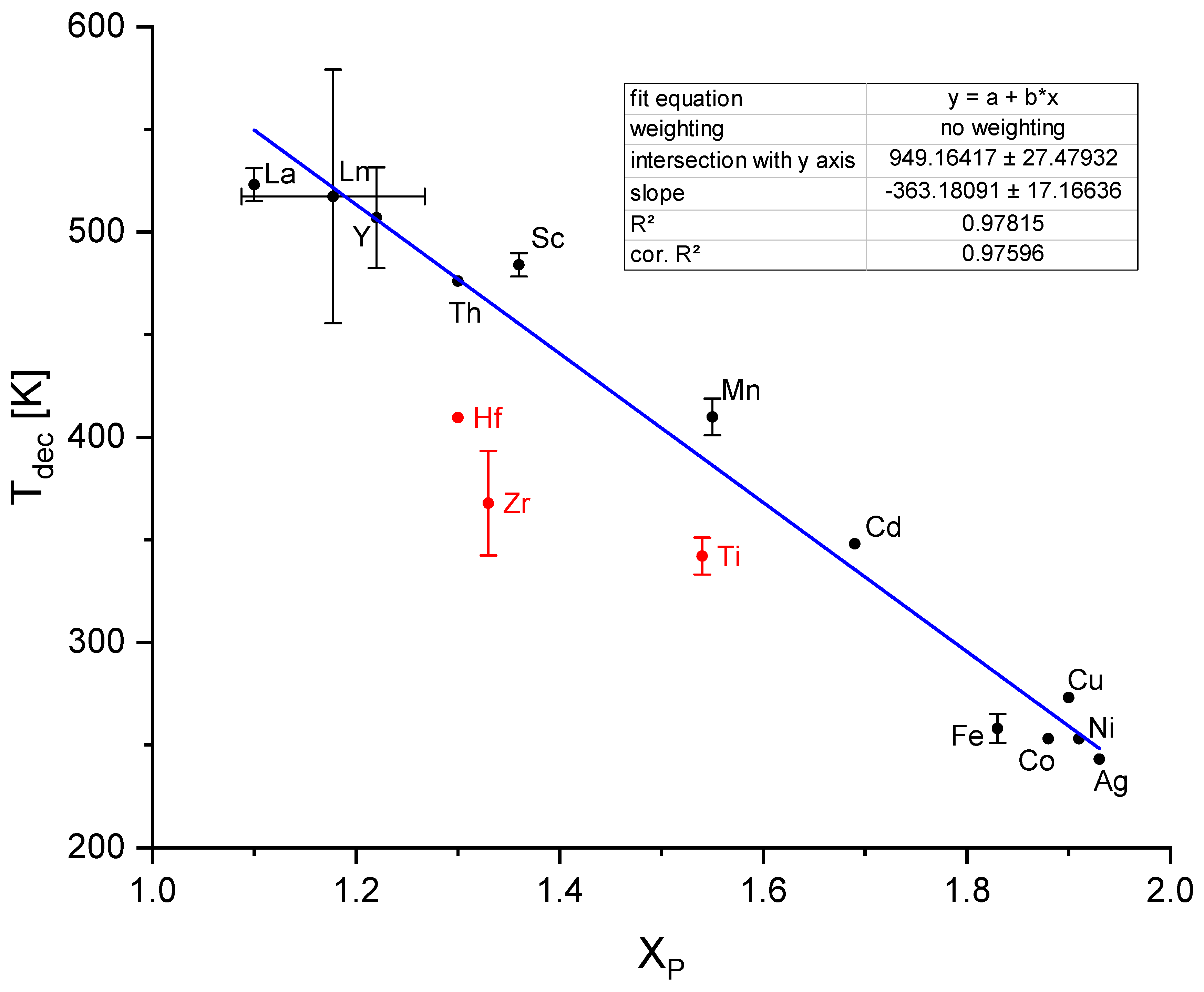
In 2006 Nakamori et al. demonstrated the existence of a correlation between the Pauling electronegativity χP of the metal of a boranate and the decomposition temperature of the boranate Td [262]. Suaréz-Alcántara and García expanded the plot to bimetallic borohydrides using an approach by Li et al. to calculate an average value for χP [174,280]. Unfortunately, the data used are inconsistent as Suaréz-Alcántara and García did not differentiate between peak and onset temperatures and the data points shown even display a significant amount of scatter although logarithmically plotted. We decided to replot the χP values (taken from [281]) of the transition metal boranates versus Td, direct proportionally. Only the boranates for which clear values are stated in the literature or a clear graph suitable for determining the decomposition onset tempreature were considered. If several, differing values were published, the arithmetic mean was used and the span of the (min, max) values are shown in the graph as error bars. As can be seen in Figure 13., the lanthanoide boranates have nearly similar χP which appears to be a consequence of the lanthanoide contraction [282]. That is why we used the arithmetic means of χP and T d for those boranates with the oxidation states +II and +III. Otherwise, the lanthanoides would be overrepresented in the the fit procedure because of the large number of values with nearly the same χP and differing Td values. Furthermore, Ti(BH4)3, Hf(BH4)4 and Zr(BH4)4 seem to be outliers as can be seen in Figure 13 (red dots). It can be assumed that their decomposition temperatures deviate from those of the other boranates because they do not posses a salt-like (ionic) crystal structure but a molecular one [174,276]. This fact seems to be unimportant for the decomposition of the molecular Th(BH4)4, which exhibit a decomposition temperature as high as expected for ionic boranates. As a result we excluded only the values of Ti(BH4)3, Hf(BH4)4 and Zr(BH4)4 in our fit (Figure 13). The equation describing our fit function is given by:
Td/K = -363.2 χP + 949.2(E1)
with an corrected R2 value of 0.97596. The much improved R2 value for the assumption of the simpler direct proportional correlation compared to the logarithmic fit in Ref. [174] can be seen as a consequence of the restriction to the most reliable data.
Different explanations for the decrease of Td with increasing χP exist [174]. Callini et al. [283] explain this result by the strength of the charge transfer from the metal cation to the tetrahydridoborate ion. In case of high values for χP, there is a small charge transfer to the anion and in turn a strong distortion of the (BH4-) units resulting in low stability combined with diborane emission [283]. This could also be explained by the distorted orbitals of the borohydride anionic molecule [283] found in the simulation performed by Du et al. [284].

4. Summary and Perspective

In this review, the development status of unstable metal hydrides for possible on-board hydrogen storage based on classical metal hydrides is reported and potential materials for the development of unstable complex metal hydride systems based on alanates or boranates has been laid out. AB2-type Laves phase alloys like TiCr2- and ZrFe2- based alloys display suitable plateau pressures and tentative tests on high pressure tank systems based on these alloys have already been conducted. However, because of the high atomic weight of transition metal elements, the hydrogen capacity of these classical metal hydrides is usually limited to ~2 wt%, which prohibits their large scale commercialization in fuel cell vehicles. Vanadium-based BCC alloys display much higher hydrogen storage capacity (>3 wt%), while the desorption plateau pressures are far below than those believed to be needed for hybrid tank systems, which leads to the incomplete dehydrogenation of the alloys under certain conditions resulting in relatively low reversible capacities. Through decades of effort, the hydrogen storage performances of these intermetallic compounds have been effectively improved and some characteristics can even meet parts of the requirements of high-pressure MH tank. Up to now, however, none of them meets the DOE 2020-2025 targets and major improvements are required to meet those. In this regard, unstable complex hydrides like transition metal alanates and borohydrides can be very interesting materials in terms of high hydrogen content and rich chemical diversity. In contrast to the main group complex metal hydrides, the known transition complex metal hydrides, i.e. mainly boranates and alanates, show very little stability. With regards to the necessary thermodynamic properties for solid state hydrogen storage, the current transition metal complex hydrides need to be regarded as non-suitable for practical applications. However, by creating mixed systems, they may offer a valuable tool box for the design of systems with the desired properties. Efforts to update the information on these complex metal hydrides in respect to new synthesis procedures and characterization techniques can supply fundamental knowledge for the task to design viable solid state hydrogen storage systems.
Materials at high-pressure conditions may show physical and chemical properties strongly deviating from the ambient pressure ones, which may create opportunities for discovering novel metastable materials with beneficial properties[285]. The pressure range up to the anticipated level of 70 MPa for compressed hydrogen in fuel cell vehicles is large enough to expect the design of a significant number of new reversible hydrogen storage materials. For instance, ZrFe2 alloy does not show any hydrogen storage properties at moderate conditions, but becomes a good hydrogen absorber at a high pressure over 100 MPa. YNi5, LaPt5 and ThNi5 alloys also only start to absorb hydrogen at high pressures up to 155 MPa [286]. However, conventional intermetallic compounds are usually composed of transition metals with heavy atomic weights. Higher capacity can be only achieved in alloys composed of light elements. To achieve higher capacities, alloys containing transition and non-transition elements should be considered. To ensure excellent reversibility, candidates should have a stable structure under high pressure. For example, light REM2~3 alloys consisting of rare earth elements (RE = Y, La, Ce, Pr, Nd, etc.), transition metal elements (TM) and non-transition metal elements (M = Al, Si, etc.) have a stable structure even under a high pressure up to several GPa. LaAl2 and CeAl2 alloys has the C15 (MgCu2 type, SG Fd3m) structure, and are stable up to the pressure over 20 Gpa [287]. Rare-earth trialuminides, REAl3 (RE=La-Yb) alloys exhibits hexagonal DO19 type (Ni3Sn, SGP63/mmc), and the cubic environment of atoms increases with the increase in the atomic number or decrease in the atomic radii of the rare-earth elements as a function of pressure [288,289]. However up to now, few researches concentrate on the hydrogen storage properties of these alloys. More attempts should be conducted under pressure up to 100 MPa or even higher.
Explorations solely relying on experimental approaches are time-consuming and inefficient. It is now well established that many important materials properties can be predicted through computational means. The heat of formation (∆H) is the key quantity to predict the stability of transition metal hydrides. Griessen et al. [290,291] calculated the ∆H of the transition metal hydrides A5BHx, A2BHx, AB2Hx, AB5Hx (A = Sc, Ti, V, Y, Zr, Nb, La, Hf, Ta, Ni, Pd; B = transition metal) using a semi-empirical model based on the electronic structure of the host alloy. Among the 1380 possible compounds, there are 44 metal hydrides with an appropriate heat of formation between -12 and -25 kJ/mol H2 [291]. Pudjanto et al. [292] also calculated the ∆H of 2208 possible hydrides based on this semi-empirical model, and 223 hydrides has a ∆H between -12 and -25 kJ/mol H2, which provides a guideline for searching new hydrogen energy storage materials. However, semi-empirical model are only effective for predicting the conventional intermetallic compounds comprising 3d, 4d and 5d transition metals. On the other hand, predictions of the hydrogen storage performances by conducting true ab-initio calculations or such based on density functional theory are also feasible [293]. In the fields of hydrogen storage materials, high-throughput computational hits were confirmed by experimental works [294,295]. Through high-throughput ab-initio computational approach, Alapati et al. [294] examined the potential utility for hydrogen storage of a large set of destabilized metal hydride reactions for which thermodynamic data had been previously unavailable. These methods are able to find many promising reactions with favorable reaction enthalpies (20 kJ/mol H2 ≤ ∆H ≤ 25 kJ/mol H2) and high hydrogen storage capacities (> 7 wt%) [294,295,296]. Lu et al. [295] experimentally demonstrated one of the predicted reactions (LiNH2 + MgH2 → LiMgN + 2H2), and found that the binary nitride LiMgN can be hydrogenated under 14 MPa hydrogen pressure at 433 K with TiCl3 as catalyst. TGA results showed that a reversible capacity of 8 wt% H2 is stored in TiCl3-doped LiMgN during the hydrogenation process. Akbarzadeh et al. [297] developed a practical formalism for studying phase diagrams of multicomponent systems through density-functional theory calculations, which can predict thermodynamically favorable hydrogen storage reactions for a given multicomponent system without having to explicitly enumerate possible reaction pathways, and optimize hydrogen storage capacity within a given window of temperatures and pressures. Wolverton et al. [298] proposed to discover novel hydrogen storage materials through the atomic scale computational approach, which gives reasonably accurate enthalpies compared to experimentally measured values across a series of metal hydrides. These results impressively demonstrate the solid guidance that computational studies can provide for the development of suitable high equilibrium pressure hydrides be it for systems generated by alloying or by mixing complex metal hydrides.

Acknowledgements

This work was supported by the National Natural Science Foundation of China Projects (52271221, 51801107). In addition to the basic funding of the Max-Planck-Society, M. F. and F. M acknowledged partially funding by the Deutsche Forschungsgemeinschaft (DFG, German Research Foundation – 449160425).

References

  1. L. Schlapbach, A. Züttel, Nature (London, U. K.) 2001, 414, 353–358.
  2. G. Marbán, T. Valdés-Solís, Int. J. Hydrogen Energy 2007, 32, 1625–1637.
  3. M. D. Redwood, M. Paterson-Beedle, L. E. Macaskie, Rev. Environ. Sci. Bio/Technol. 2009, 8, 149–185.
  4. J. O. Bockris, Int. J. Hydrog. Energy 2013, 38, 2579–2588.
  5. H. T. Hwang, A. Varma, Curr. Opin. Chem. Eng. 2014, 5, 42–48.
  6. U. Eberle, M. Felderhoff, F. Schüth, Angew. Chem., Int. Ed. Engl. 2009, 48, 6608–6630.
  7. S. Satyapal, J. Petrovic, C. Read, G. Thomas, G. Ordaz, Catal. Today 2007, 120, 246–256.
  8. N. Heinemann, J. Alcalde, J. M. Miocic, S. J. T. Hangx, J. Kallmeyer, C. Ostertag-Henning, A. Hassanpouryouzband, E. M. Thaysen, G. J. Strobel, C. Schmidt-Hattenberger et al., Energy Environ. Sci. 2021, 14, 853–864.
  9. D. J. Durbin, C. Malardier-Jugroot, Int. J. Hydrogen Energy 2013, 38, 14595–14617.
  10. B. Zohuri, Hydrogen Energy: Challanges and Solution for a Cleaner Future, Springer International Publishing, Cham, 2019.
  11. T. Yoshida, K. Kojima, Electrochem. Soc. Interface 2015, 24, 45–49.
  12. N. Takeichi, Int. J. Hydrogen Energy 2003, 1121–1129.
  13. D. Mori, K. Hirose, Int. J. Hydrogen Energy 2009, 34, 4569–4574.
  14. D. Mori, K. D. Mori, K. Hirose, N. Haraikawa, T. Takiguchi, T. Shinozawa, T. Matsunaga, K. Toh, K. Fujita, A. Kumano, H. Kubo in SAE Technical Paper Series, SAE International400 Commonwealth Drive, Warrendale, PA, United States, 2007.
  15. Y. Kojima, Y. Kawai, S. Towata, T. Matsunaga, T. Shinozawa, M. Kimbara, J. Alloys Compd. 2006, 419, 256–261.
  16. T. MATSUNAGA, M. KON, K. WASHIO, T. SHINOZAWA, M. ISHIKIRIYAMA, Int. J. Hydrogen Energy 2009, 34, 1458–1462.
  17. D. Mori, N. Haraikawa, N. Kobayashi, H. Kubo, K. TOH, M. Tsuzuki, T. Shinozawa, T. Matsunaga, MRS Online Proc. Libr. 2005, 884, 72–78.
  18. Y. -H. Xu, C.-P. Chen, W.-X. Geng, Q.-D. Wang, Int. J. Hydrogen Energy 2001, 26, 593–596.
  19. K. Young, T. Ouchi, M. A. Fetcenko, J. Alloys Compd. 2009, 480, 428–433.
  20. M. V. Lototskyy, I. Tolj, L. Pickering, C. Sita, F. Barbir, V. Yartys, Prog. Nat. Sci.: Mater. Int. 2017, 27, 3–20.
  21. F. Marques, M. Balcerzak, F. Winkelmann, G. Zepon, M. Felderhoff, Energy Environ. Sci. 2021, 14, 5191–5227.
  22. D. P. Shoemaker, C. B. Shoemaker, J. Less-Common Met. 1979, 68, 43–58.
  23. D. G. Westlake, J. Less-Common Met. 1983, 90, 251–273.
  24. D. G. Westlake, J. Less-Common Met. 1983, 91, 1–20.
  25. J. Bodega, J. F. Fernández, F. Leardini, J. R. Ares, C. Sánchez, J. Phys. Chem. Solids 2011, 72, 1334–1342.
  26. A. R. Merlino, C. R. Luna, A. Juan, M. E. Pronsato, Int. J. Hydrogen Energy 2016, 41, 2700–2710.
  27. D. G. Ivey, D. O. Northwood, Z. Phys. Chem. 1986, 147, 191–209.
  28. J. R. Johnson, J. J. Reilly, Inorg. Chem. 1978, 17, 3103–3108.
  29. J. R. Johnson, J. Less-Common Met. 1980, 73, 345–354.
  30. S. Klyamkin, Int. J. Hydrogen Energy 1999, 24, 149–152.
  31. T. L. Murashkina, M. S. Syrtanov, R. S. Laptev, E. N. Stepanova, A. M. Lider, Int. J. Hydrogen Energy 2019, 44, 10732–10743.
  32. T. L. Murashkina, M. S. Syrtanov, R. S. Laptev, A. M. Lider, Int. J. Hydrogen Energy 2019, 44, 6709–6719.
  33. T. L. Murashkina, M. S. Syrtanov, A. S. Shabunin, R. S. Laptev, J. Surf. Invest.: X-Ray, Synchrotron Neutron Tech. 2019, 13, 146–153.
  34. Y. Moriwaki, T. Gamo, T. Iwaki, J. Less-Common Met. 1991, 172-174, 1028–1035.
  35. N. Nagasako, A. Fukumoto, K. Miwa, Phys. Rev. B 2002, 66.
  36. M. Kandavel, V. V. Bhat, A. Rougier, L. Aymard, G.-A. Nazri, J.-M. Tarascon, Int. J. Hydrogen Energy 2008, 33, 3754–3761.
  37. F. Li, J. Zhao, D. Tian, H. Zhang, X. Ke, B. Johansson, J. Appl. Phys. 2009, 105, 43707.
  38. Z. -S. Nong, J.-C. Zhu, Y. Cao, X.-W. Yang, Z.-H. Lai, Y. Liu, Phys. B 2013, 419, 11–18.
  39. Z. -S. Nong, J.-C. Zhu, X.-W. Yang, Y. Cao, Z.-H. Lai, Y. Liu, W. Sun, Solid State Sci. 2014, 32, 1–7.
  40. X. Guo, E. Wu, J. Alloys Compd. 2008, 455, 191–196.
  41. X. GUO, E. WU, S. WANG, Rare Met. 2006, 25, 218–223.
  42. W. Li, E. Wu, P. Ma, K. Sun, D. Chen, Int. J. Energy Res. 2013, 37, 686–697.
  43. J. J. Reilly, Z. Phys. Chem. 1979, 117, 155–184.
  44. J. R. Johnson, J. J. J. R. Johnson, J. J. Reilly, THE METAL HYDRIDE RESEARCH AND DEVELOPMENT PROGRAM AT BROOKHAVEN NATIONAL LABORATORY, 1978.
  45. J. R. Johnson, J. J. Reilly, F. Reidinger, L. M. Corliss, J. M. Hastings, J. Less-Common Met. 1982, 88, 107–114.
  46. O. Beeri, D. Cohen, Z. Gavra, J. R. Johnson, M. H. Mintz, J. Alloys Compd. 2000, 299, 217–226.
  47. O. Beeri, D. Cohen, Z. Gavra, M. H. Mintz, J. Alloys Compd. 2003, 352, 111–122.
  48. D. S. dos Santos, M. Bououdina, D. Fruchart, J. Alloys Compd. 2002, 340, 101–107.
  49. U. Ulmer, M. Dieterich, A. Pohl, R. Dittmeyer, M. Linder, M. Fichtner, Int. J. Hydrogen Energy 2017, 42, 20103–20110.
  50. K. Young, T. Ouchi, J. Yang, M. A. Fetcenko, Int. J. Hydrogen Energy 2011, 36, 11137–11145.
  51. K. Young, J. Nei, B. Huang, M. A. Fetcenko, Int. J. Hydrogen Energy 2011, 36, 11146–11154.
  52. S. -M. Lee, H. Lee, J.-H. Kim, P. S. Lee, J.-Y. Lee, J. Alloys Compd. 2000, 308, 259–268.
  53. S. -. Lee, S.-H. Kim, S.-W. Jeon, J.-Y. Lee, J. Electrochem. Soc. 2000, 4464–4469.
  54. Y. Xu, G. Wang, C. Chen, Q. Wang, X. Wang, Int. J. Hydrogen Energy 2007, 32, 1050–1058.
  55. V. S. Marinin, K. R. Umerenkova, O. V. Volovchuk, Int. J. Hydrogen Energy 2011, 36, 1359–1363.
  56. J. -G. Park, H.-Y. Jang, S.-C. Han, P. S. Lee, J.-Y. Lee, J. Alloys Compd. 2001, 325, 293–298.
  57. T. L. Pourpoint, V. Velagapudi, I. Mudawar, Y. Zheng, T. S. Fisher, Int. J. Heat Mass Transfer 2010, 53, 1326–1332.
  58. Z. Cao, L. Ouyang, H. Wang, J. Liu, D. Sun, Q. Zhang, M. Zhu, Int. J. Hydrogen Energy 2015, 40, 2717–2728.
  59. Z. Cao, L. Ouyang, H. Wang, J. Liu, L. Sun, M. Zhu, J. Alloys Compd. 2015, 639, 452–457.
  60. Z. Chen, X. Xiao, L. Chen, X. Fan, L. Liu, S. Li, H. Ge, Q. Wang, Int. J. Hydrogen Energy 2013, 38, 12803–12810.
  61. Z. Chen, X. Xiao, L. Chen, X. Fan, L. Liu, S. Li, H. Ge, Q. Wang, J. Alloys Compd. 2014, 585, 307–311.
  62. L. Liu, L. Chen, X. Xiao, C. Xu, J. Sun, S. Li, H. Ge, L. Jiang, J. Alloys Compd. 2015, 636, 117–123.
  63. Z. Yao, L. Liu, X. Xiao, C. Wang, L. Jiang, L. Chen, J. Alloys Compd. 2018, 731, 524–530.
  64. J. Li, L. Xu, X. Jiang, X. Li, Prog. Nat. Sci.: Mater. Int. 2018, 28, 470–477.
  65. J. Li, X. Jiang, G. Li, X. Li, Int. J. Hydrogen Energy 2019, 44, 15087–15099.
  66. J. Li, X. Jiang, Z. Li, L. Jiang, X. Li, Int. J. Energy Res. 2019, 43, 5759–5774.
  67. J. Puszkiel, J. M. Bellosta von Colbe, J. Jepsen, S. V. Mitrokhin, E. Movlaev, V. Verbetsky, T. Klassen, Energies 2020, 13, 2751.
  68. M. S. Granovsky, D. Arias, J. Nucl. Mater. 1996, 229, 29–35.
  69. T. Zotov, E. Movlaev, S. Mitrokhin, V. Verbetsky, J. Alloys Compd. 2008, 459, 220–224.
  70. S. M. Filipek, I. Jacob, V. Paul-Boncour, A. Percheron-Guegan, I. Marchuk, D. Mogilyanski, J. Pielaszek, ChemInform 2002, 33, no.
  71. V. Paul-Boncour, F. Bourée-Vigneron, S. M. Filipek, I. Marchuk, I. Jacob, A. Percheron-Guégan, J. Alloys Compd. 2003, 356-357, 69–72.
  72. E. D. Koultoukis, S. S. Makridis, E. Pavlidou, P. de Rango, A. K. Stubos, Int. J. Hydrogen Energy 2014, 39, 21380–21385.
  73. S. Banerjee, A. Kumar, C. Pillai, Intermetallics 2014, 51, 30–36.
  74. A. Jain, R. K. Jain, S. Agarwal, R. K. Sharma, S. K. Kulshrestha, I. P. Jain, J. Alloys Compd. 2008, 454, 31–37.
  75. R. B. Sivov, T. A. Zotov, V. N. Verbetsky, D. S. Filimonov, K. V. Pokholok, J. Alloys Compd. 2011, 509, S763–S769.
  76. R. B. Sivov, V. A. Somenkov, V. P. Glazkov, V. N. Verbetsky, Inorg. Mater. 2012, 48, 792–795.
  77. V. A. Yartys, R. V. Denys, C. J. Webb, J. P. Mæhlen, E. M. Gray, T. Blach, O. Isnard, L. C. Barnsley, J. Alloys Compd. 2011, 509, S817–S822.
  78. R. B. Sivov, T. A. Zotov, V. N. Verbetsky, Inorg. Mater. 2010, 46, 372–376.
  79. M. H. Mendelsohn, D. M. Gruen, J. Less-Common Met. 1980, 74, 449–453.
  80. T. B. Zhang, X. F. Wang, R. Hu, J. S. Li, X. W. Yang, X. Y. Xue, H. Z. Fu, Int. J. Hydrogen Energy 2012, 37, 2328–2335.
  81. T. P. Yadav, R. R. Shahi, O. N. Srivastava, Int. J. Hydrogen Energy 2012, 37, 3689–3696.
  82. K. Kanematsu, J. Phys. Soc. Jpn. 1971, 31, 1355–1360.
  83. H. Fujii, V. K. Sinha, F. Pourarian, W. E. Wallace, J. Less-Common Met. 1982, 85, 43–54.
  84. A. Jain, Jain, R. Agarwal, S., Ganesan, V. Lalla, N. P., D. M. Phase, I. P. Jain, Int. J. Hydrogen Energy 2007, 32, 3965–3971.
  85. S. Hirosawa, F. Pourarian, V. K. Sinha, W. E. Wallace, J. Magn. Magn. Mater. 1983, 38, 159–164.
  86. M. Bereznitsky, I. Jacob, J. Bloch, M. H. Mintz, J. Alloys Compd. 2003, 351, 180–183.
  87. J. Coaquira, H. R. Rechenberg, J. Mestnik Filho, J. Magn. Magn. Mater. 1999, 196-197, 677–679.
  88. J. Coaquira, H. R. Rechenberg, J. Mestnik Filho, J. Alloys Compd. 1999, 288, 42–49.
  89. G. Y. Yu, W. E. Wallace, J. Solid State Chem. 1986, 65, 356–362.
  90. V. Sinha, F. Pourarian, W. Wallace, J. Less-Common Met. 1982, 87, 283–296.
  91. R. S. T. Zotov, E. R. S. T. Zotov, E. Mitrohkin, E. A. Movlaev, V. Verbetsky, Carbon Nanomaterials in Clean Energy Hydrogen Systems 2008, 699–704.
  92. T. A. Zotov, R. B. Sivov, E. A. Movlaev, S. V. Mitrokhin, V. N. Verbetsky, J. Alloys Compd. 2011, 509, S839–S843.
  93. D. J. Davidson, O. N. Srivastava, Int. J. Hydrog. Energy 2001, 26, 219–223.
  94. D. Davidson, Int. J. Hydrog. Energy 2003, 28, 1425–1431.
  95. R. B. Sivov, T. A. Zotov, V. N. Verbetsky, Int. J. Hydrogen Energy 2011, 36, 1355–1358.
  96. L. Jiang, Y. Tu, H. Tu, L. Chen, J. Alloys Compd. 2015, 627, 161–165.
  97. Z. Cao, L. Ouyang, H. Wang, J. Liu, L. Sun, M. Felderhoff, M. Zhu, Int. J. Hydrogen Energy 2016, 41, 11242–11253.
  98. C. Zhou, H. Wang, L. Z. Ouyang, J. W. Liu, M. Zhu, J. Alloys Compd. 2019, 806, 1436–1444.
  99. C. Qin, C. Zhou, L. Ouyang, J. Liu, M. Zhu, T. Sun, H. Wang, Int. J. Hydrogen Energy 2020, 45, 9836–9844.
  100. M. Kandavel, S. Ramaprabhu, J. Phys.: Condens. Matter 2003, 15, 7501–7517.
  101. S. L. Li, H. H. Cheng, X. X. Deng, W. Chen, D. M. Chen, K. Yang, J. Alloys Compd. 2008, 460, 186–190.
  102. M. Kandavel, S. Ramaprabhu, J. Alloys Compd. 2004, 381, 140–150.
  103. E. Akiba, H. Iba, Intermetallics 1998, 6, 461–470.
  104. X. Yu, Z. Wu, B. Xia, T. Huang, J. Chen, Z. Wang, N. Xu, J. Mater. Res. 2003, 18, 2533–2536.
  105. K. Nomura, E. Akiba, J. Alloys Compd. 1995, 231, 513–517.
  106. H. Yukawa, A. Teshima, D. Yamashita, S. Ito, S. Yamaguchi, M. Morinaga, J. Alloys Compd. 2002, 337, 264–268.
  107. J. -H. Yoo, G. Shim, C.-N. Park, W.-B. Kim, S.-W. Cho, Int. J. Hydrogen Energy 2009, 34, 9116–9121.
  108. H. Arashima, F. Takahashi, T. Ebisawa, H. Itoh, T. Kabutomori, J. Alloys Compd. 2003, 356-357, 405–408.
  109. C. Wu, Y. Yan, Y. Chen, M. Tao, X. Zheng, Int. J. Hydrogen Energy 2008, 33, 93–97.
  110. S. Ono, K. Nomura, Y. Ikeda, J. Less-Common Met. 1980, 72, 159–165.
  111. B. Nowak, S. Hayashi, K. Hayamizu, O. Yamamoto, J. Less-Common Met. 1986, 123, 75–84.
  112. J. Matsuda, E. Akiba, J. Alloys Compd. 2013, 581, 369–372.
  113. J. F. Lynch, J. J. Reilly, F. Millot, Solid State Commun. 1978, 26, iv.
  114. V. N. Verbetsky, T. A. Zotov, A. V. Tatarintsev, E. A. Movlaev, Inorg. Mater. 2013, 49, 149–152.
  115. K. Asano, S. Hayashi, Y. Nakamura, E. Akiba, J. Alloys Compd. 2012, 524, 63–68.
  116. K. Asano, S. Hayashi, Y. Nakamura, E. Akiba, J. Alloys Compd. 2010, 507, 399–404.
  117. V. N. Verbetsky, T. A. Zotov, E. A. Movlaev, Inorg. Mater.: Appl. Res. 2014, 5, 70–74.
  118. T. V. B. Phung, H. Ogawa, an van Dinh, O. H. Nguyen, Y. Shibutani, K. Asano, Y. Nakamura, E. Akiba, Theor. Chem. Acc. 2019, 138.
  119. S. Miraglia, P. de Rango, S. Rivoirard, D. Fruchart, J. Charbonnier, N. Skryabina, J. Alloys Compd. 2012, 536, 1–6.
  120. T. Tamura, T. Kazumi, A. Kamegawa, H. Takamura, M. Okada, J. Alloys Compd. 2003, 356-357, 505–509.
  121. H. Itoh, H. Arashima, K. Kubo, T. Kabutomori, K. Ohnishi, J. Alloys Compd. 2005, 404-406, 417–420.
  122. J. F. Lynch, A. J. Maeland, G. G. Libowitz, Z. Phys. Chem. 1985, 145, 51–59.
  123. G. Fu, F. Wang, J. Wang, M. H. Rong, Z. M. Wang, G. H. Rao, H. Y. Zhou, Mater. Sci. Forum 2016, 847, 3–7.
  124. A. Guéguen, J.-M. Joubert, M. Latroche, J. Alloys Compd. 2011, 509, 3013–3018.
  125. S. K. Callear, A. J. Ramirez-Cuesta, K. Kamazawa, S. Towata, T. Noritake, S. F. Parker, M. O. Jones, J. Sugiyama, M. Ishikiriyama, W. I. F. David, Phys. Chem. Chem. Phys. 2014, 16, 16563–16572.
  126. S. Basak, K. Shashikala, P. Sengupta, S. K. Kulshrestha, Int. J. Hydrogen Energy 2007, 32, 4973–4977.
  127. Y. Yan, Y. Chen, H. Liang, C. Wu, M. Tao, T. Mingjing, J. Alloys Compd. 2006, 426, 253–255.
  128. T. Kuriiwa, T. Maruyama, A. Kamegawa, M. Okada, Int. J. Hydrogen Energy 2010, 35, 9082–9087.
  129. K. Goshome, N. Endo, M. Tetsuhiko, Int. J. Hydrogen Energy 2019, 44, 10800–10807.
  130. S. Selvaraj, A. Jain, S. Kumar, T. Zhang, S. Isobe, H. Miyaoka, Y. Kojima, T. Ichikawa, Int. J. Hydrogen Energy 2018, 43, 2881–2889.
  131. Y. Nonobe, IEEJ Trans. Electr. Electron. Eng. 2017, 12, 5–9.
  132. S. Kumar, A. Jain, T. Ichikawa, Y. Kojima, G. K. Dey, Renewable Sustainable Energy Rev. 2017, 72, 791–800.
  133. A. Lys, J. O. Fadonougbo, M. Faisal, J.-Y. Suh, Y.-S. Lee, J.-H. Shim, J. Park, Y. W. Cho, Hydrogen 2020, 1, 38–63.
  134. K. Young, D. F. Wong, S. Yasuoka, J. Ishida, J. Nei, J. Koch, J. Power Sources 2014, 251, 170–177.
  135. T. Bibienne, C. Gosselin, J.-L. Bobet, J. Huot, Appl. Sci. 2018, 8, 1151.
  136. Y. Yan, Y. Chen, C. Wu, M. Tao, H. Liang, J. Power Sources 2007, 164, 799–802.
  137. C. Wu, X. Zheng, Y. Chen, M. Tao, G. Tong, J. Zhou, Int. J. Hydrogen Energy 2010, 35, 8130–8135.
  138. Y. Mao, S. Yang, C. Wu, L. Luo, Y. Chen, J. Alloys Compd. 2017, 705, 533–538.
  139. S. Yang, F. Yang, C. Wu, Y. Chen, Y. Mao, L. Luo, J. Alloys Compd. 2016, 663, 460–465.
  140. M. B. Ley, L. H. Jepsen, Y.-S. Lee, Y. W. Cho, J. M. Bellosta von Colbe, M. Dornheim, M. Rokni, J. O. Jensen, M. Sloth, Y. Filinchuk et al., Mater. Today 2014, 17, 122–128.
  141. B. Bogdanović, M. Schwickardi, J. Alloys Compd. 1997, 253-254, 1–9.
  142. K. Suárez-Alcántara, J. R. Tena-Garcia, R. Guerrero-Ortiz, Materials 2019, 12.
  143. G. Monnier, Bull. Soc. Chim. Fr. 1955, 1138.
  144. M. E. Kost, A. I. Golovanova, Izv. Akad. Nauk SSSR, Neorg. Mater. 1978, 14, 1732–1734.
  145. H. Neumaier, D. Büchel, G. Ziegelmaier, Z. Anorg. Allg. Chem. 1966, 345, 46–52.
  146. M. E. Kost, A. I. Golovanova, Izv. Akad. Nauk SSSR, Ser. Khim. 1975, 5, 991–994.
  147. N. T. Kuznetsov, N. N. Mal'tseva, A. I. Golovanova, Russ. J. Inorg. Chem. 1985, 30, 1604–1606.
  148. G. Monnier, Ann. chim. 1957, 13, 33.
  149. C. Weidenthaler, A. Pommerin, M. Felderhoff, W. Sun, C. Wolverton, B. Bogdanović, F. Schüth, J. Am. Chem. Soc. 2009, 131, 16735–16743.
  150. E. Wiberg, W. Henle, Z. Naturforsch. B 1951, 6, 461–462.
  151. E. Wiberg, H. Neumaier, Inorg. Nucl. Chem. Lett. 1965, 1, 35–37.
  152. E. Wiberg, W. Henle, Z. Naturforsch. B 1951, 6, 461.
  153. H. Neumaier, Dissertation, Ludwig-Maximilians-Universität, München, 1961.
  154. F. Habermann, K. Burkmann, B. Hansel, B. Störr, C. Schimpf, J. Seidel, M. Bertau, F. Mertens, Dalton Trans. 2023, 52, 4880–4890.
  155. E. Wiberg, R. Usón, Z. Naturforsch. B 1951, 6, 393.
  156. A. I. Golovanova, M. E. Kost, V. I. Mikheeva, Bull. Acad. Sci. USSR, Div. Chem. Sci. (Engl. Transl.) 1973, 22, 1410–1413.
  157. G. Jander, K. Kraffczyk, Z. Anorg. Allg. Chem. 1956, 283, 217–229.
  158. E. Wiberg, W. Henle, Z. Naturforsch. B 1952, 7, 250–251.
  159. W. E. Reid, J. M. Bish, A. Brenner, J. Electrochem. Soc. 1957, 104, 21–29.
  160. G. L. Soloveichik, B. M. Bulychev, Russ. Chem. Rev. 1983, 52, 43–60.
  161. E. C. Ashby, R. A. Kovar, Inorg. Chem. 1977, 16, 1437–1440.
  162. E. C. Ashby, H. S. Prasad, Inorg. Chem. 1975, 14, 1608–1614.
  163. A. Pommerin, A. Wosylus, M. Felderhoff, F. Schüth, C. Weidenthaler, Inorg. Chem. 2012, 51, 4143–4150.
  164. G. W. Schaeffer, J. S. Roscoe, A. C. Stewart, J. Am. Chem. Soc. 1956, 78, 729–733.
  165. M. E. Kost, A. I. Golovanova, Zh. Neorg. Khim. 1977, 22, 977–979.
  166. E. Wiberg, H. Neumaier, Z. Anorg. Allg. Chem. 1965, 340, 189–200.
  167. E. Wiberg, R. Usón, Z. Naturforsch. B 1951, 6, 392–393.
  168. M. E. Kost, A. I. Golovanova, Zh. Neorg. Khim. 1977, 22, 832–833.
  169. Z. Cao, L. Ouyang, H. Wang, J. Liu, M. Felderhoff, M. Zhu, J. Mater. Chem. A 2017, 5, 6042–6046.
  170. Z. Cao, M. Felderhoff, Int. J. Hydrogen Energy 2021, 46, 26437–26444.
  171. H. -W. Li, Y. Yan, S.-I. Orimo, A. Züttel, C. M. Jensen, Energies 2011, 4, 185–214.
  172. J. J. Vajo, F. Mertens, C. C. Ahn, R. C. Bowman, B. Fultz, J. Phys. Chem. B 2004, 108, 13977–13983.
  173. J. J. Vajo, S. L. Skeith, F. Mertens, J. Phys. Chem. B 2005, 109, 3719–3722.
  174. K. Suárez-Alcántara, J. R. Tena García, Materials 2021, 14, 2561–2616.
  175. H. Nöth, M. H. Nöth, M. Seitz, J. Chem. Soc., Chem. Commun. 1976, 1004a-1004a.
  176. B. Lobkovskii, S. E. Kravchenko, K. N. Semenenko, J. Struct. Chem. 1977, 18, 312–314.
  177. J. H. Morris, W. E. Smith, J. Chem. Soc. D 1970, 245a.
  178. H. Nöth, L. P. Winter, Z. Anorg. Allg. Chem. 1972, 389, 225–234.
  179. Y. Nakamori, H. Li, K. Miwa, S. Towata, S.-I. Orimo, Mater. Trans. 2006, 47, 1898–1901.
  180. Y. Nakamori, H.-W. Li, K. Kikuchi, M. Aoki, K. Miwa, S. Towata, S. Orimo, J. Alloys Compd. 2007, 446-447, 296–300.
  181. Y. Nakamori, H.-W. Li, M. Matsuo, K. Miwa, S. Towata, S. Orimo, J. Phys. Chem. Solids 2008, 69, 2292–2296.
  182. E. Jeon, Y. Cho, J. Alloys Compd. 2006, 422, 273–275.
  183. M. Y. Song, Y. J. Kwak, S. N. Kwon, S. H. Lee, I. W. Park, Korean J. Met. Mater. 2015, 53, 500–505.
  184. S. Srinivasan, D. Escobar, M. Jurczyk, Y. Goswami, E. Stefanakos, J. Alloys Compd. 2008, 462, 294–302.
  185. D. Ravnsbaek, Y. Filinchuk, Y. Cerenius, H. J. Jakobsen, F. Besenbacher, J. Skibsted, T. R. Jensen, Angew. Chem. Int. Ed. 2009, 48, 6659–6663.
  186. Q. Gu, L. Gao, Y. Guo, Y. Tan, Z. Tang, K. S. Wallwork, F. Zhang, X. Yu, Energy Environ. Sci. 2012, 5, 7590.
  187. V. I. Mikheeva, N. N. Mal'tseva, L. S. Alekseeva, Russ. J. Inorg. Chem. 1968, 13, 682–685.
  188. C. -H. Yang, W.-T. Tsai, J.-K. Chang, Int. J. Hydrogen Energy 2011, 36, 4993–4999.
  189. D. Korablov, D. B. Ravnsbæk, V. Ban, Y. Filinchuk, F. Besenbacher, T. R. Jensen, Int. J. Hydrogen Energy 2013, 38, 8376–8383.
  190. K. Park, H.-S. Lee, A. Remhof, Y.-S. Lee, Y. Yan, M.-Y. Kim, S. J. Kim, A. Züttel, Y. W. Cho, Int. J. Hydrogen Energy 2013, 38, 9263–9270.
  191. H. Nöth, Angew. Chem. 1961, 73, 371–383.
  192. E. Wiberg, W. Henle, Z. Naturforsch. B 1952, 7, 575–576.
  193. G. W. Rice, R. L. Woodin, J. Am. Chem. Soc. 1988, 71, C–181.
  194. B. Richter, J. B. Grinderslev, K. T. Møller, M. Paskevicius, T. R. Jensen, Inorg. Chem. 2018, 57, 10768–10780.
  195. J. B. Grinderslev, K. T. Møller, M. Bremholm, T. R. Jensen, Inorg. Chem. 2019, 58, 5503–5517.
  196. L. J. Bannenberg, M. Heere, H. Benzidi, J. Montero, E. M. Dematteis, S. Suwarno, T. Jaroń, M. Winny, P. A. Orłowski, W. Wegner et al., Int. J. Hydrogen Energy 2020, 45, 33687–33730.
  197. M. Sharma, E. Didelot, A. Spyratou, L. M. Lawson Daku, R. Černý, H. Hagemann, Inorg. Chem. 2016, 55, 7090–7097.
  198. A. Remhof, A. Borgschulte, O. Friedrichs, P. Mauron, Y. Yan, A. Züttel, Scr. Mater. 2012, 66, 280–283.
  199. E. Roedern, Y.-S. Lee, M. B. Ley, K. Park, Y. W. Cho, J. Skibsted, T. R. Jensen, J. Mater. Chem. A 2016, 4, 8793–8802.
  200. M. B. Ley, M. Paskevicius, P. Schouwink, B. Richter, D. A. Sheppard, C. E. Buckley, T. R. Jensen, Dalton Trans. 2014, 43, 13333–13342.
  201. B. Richter, D. B. Ravnsbæk, N. Tumanov, Y. Filinchuk, T. R. Jensen, Dalton Trans. 2015, 44, 3988–3996.
  202. Deutsches Institut für Normung e., V. , Kunststoffe - Dynamische Differenz-Thermoanalyse (DSC) - Teil 1: Allgemeine Grundlagen (ISO 11357-1:2016), 83.080.01, 2017-02-00, Beuth Verlag GmbH, Berlin.
  203. M. B. Ley, M. Jørgensen, R. Černý, Y. Filinchuk, T. R. Jensen, Inorg. Chem. 2016, 55, 9748–9756.
  204. F. C. Gennari, M. R. Esquivel, J. Alloys Compd. 2009, 485, L47–L51.
  205. B. J. Zhang, B. H. Liu, Z. P. Li, J. Alloys Compd. 2011, 509, 751–757.
  206. J. Aubry, G. Monnier, Bull. Soc. Chim. Fr. 1955, 438.
  207. A. C. Stewart, G. W. Schaeffer, J. Inorg. Nucl. Chem. 1956, 3, 194–197.
  208. E. Wiberg, Angew. Chem. 1953, 65, 16–33.
  209. T. J. Klingen, Inorg. Chem. 1964, 3, 1058–1059.
  210. E. Wiberg, W. Henle, Z. Naturforsch. B 1952, 7, 582.
  211. N. N. Mal'tseva, Russ. J. Inorg. Chem. 1697, 12, 1338–1341.
  212. D. Blanchard, M. Zatti, T. Vegge, J. Alloys Compd. 2013, 547, 76–80.
  213. D. B. Ravnsbæk, L. H. Sørensen, Y. Filinchuk, F. Besenbacher, T. R. Jensen, Angew. Chem. Int. Ed. 2012, 51, 3582–3586.
  214. T. D. Humphries, M. B. Ley, C. Frommen, K. T. Munroe, T. R. Jensen, B. C. Hauback, J. Mater. Chem. A 2015, 3, 691–698.
  215. W. Wegner, T. Jaroń, W. Grochala, J. Alloys Compd. 2018, 744, 57–63.
  216. J. E. Olsen, C. Frommen, T. R. Jensen, M. D. Riktor, M. H. Sørby, B. C. Hauback, RSC Adv. 2014, 4, 1570–1582.
  217. M. Heere, S. H. Payandeh GharibDoust, C. Frommen, T. D. Humphries, M. B. Ley, M. H. Sørby, T. R. Jensen, B. C. Hauback, Phys. Chem. Chem. Phys. 2016, 18, 24387–24395.
  218. F. C. Gennari, J. Alloys Compd. 2013, 581, 192–195.
  219. J. Andrade-Gamboa, J. A. Puszkiel, L. Fernández-Albanesi, F. C. Gennari, Int. J. Hydrog. Energy 2010, 35, 10324–10328.
  220. M. B. Ley, S. Boulineau, R. Janot, Y. Filinchuk, T. R. Jensen, J. Phys. Chem. C 2012, 116, 21267–21276.
  221. K. Burkmann, F. Habermann, E. Schumann, J. Kraus, B. Störr, H. Schmidt, E. Brendler, J. Seidel, K. Bohmhammel, J. Kortus et al., New J. Chem. 2024, 48, 2743–2754.
  222. B. D. James, R. K. Nanda, M. G. H. Wallbridge, J. Chem. Soc. A 1966, 1, 182–184.
  223. J. C. Green, M. de Simone, M. Coreno, A. Jones, H. M. I. Pritchard, G. S. McGrady, Inorg. Chem. 2005, 44, 7781–7793.
  224. T. J. Marks, L. A. Shimp, J. Am. Chem. Soc. 1972, 94, 1542–1550.
  225. A. Haaland, D. J. Shorokhov, A. V. Tutukin, H. V. Volden, O. Swang, G. S. McGrady, N. Kaltsoyannis, A. J. Downs, C. Y. Tang, J. F. C. Turner, Inorg. Chem. 2002, 41, 6646–6655.
  226. E. R. Bernstein, T. A. Keiderling, J. Chem. Phys. 1973, 59, 2105–2122.
  227. A. L. Wayda, L. F. Schneemeyer, R. L. Opila, Appl. Phys. Lett. 1988, 53, 361–363.
  228. R. W. Broach, I. S. Chuang, T. J. Marks, J. M. Williams, Inorg. Chem. 1983, 22, 1081–1084.
  229. H. R. Hoekstra, J. J. Katz, J. Am. Chem. Soc. 1949, 71, 2488–2492.
  230. W. Wegner, T. Jaroń, W. Grochala, Int. J. Hydrogen Energy 2014, 39, 20024–20030.
  231. S. Payandeh GharibDoust, M. Heere, M. H. Sørby, M. B. Ley, D. B. Ravnsbæk, B. C. Hauback, R. Černý, T. R. Jensen, Dalton Trans. 2016, 45, 19002–19011.
  232. S. Payandeh GharibDoust, M. Brighi, Y. Sadikin, D. B. Ravnsbæk, R. Černý, J. Skibsted, T. R. Jensen, J. Phys. Chem. C 2017, 121, 19010–19021.
  233. R. Liu, D. Reed, D. Book, J. Alloys Compd. 2012, 515, 32–38.
  234. N. A. Tumanov, E. Roedern, Z. Łodziana, D. B. Nielsen, T. R. Jensen, A. V. Talyzin, R. Černý, D. Chernyshov, V. Dmitriev, T. Palasyuk et al., Chem. Mater. 2016, 28, 274–283.
  235. E. Roedern, T. R. Jensen, J. Phys. Chem. C 2014, 118, 23567–23574.
  236. R. A. Varin, A. S. Bidabadi, Int. J. Hydrogen Energy 2014, 39, 11620–11632.
  237. R. A. Varin, D. K. Mattar, A. S. Bidabadi, M. Polanski, J. Energy Chem. 2017, 26, 24–34.
  238. R. A. Varin, A. S. Bidabadi, M. Polanski, M. Biglari, L. Stobinski, Mater. Res. Bull. 2018, 100, 394–406.
  239. S. Payandeh GharibDoust, M. Heere, C. Nervi, M. H. Sørby, B. C. Hauback, T. R. Jensen, Dalton Trans. 2018, 47, 8307–8319.
  240. R. H. Banks, N. M. Edelstein, B. Spencer, D. H. Templeton, A. Zalkin, J. Am. Chem. Soc. 1980, 102, 620–623.
  241. R. H. Banks, N. M. Edelstein, R. R. Rietz, D. H. Templeton, A. Zalkin, J. Am. Chem. Soc. 1978, 100, 1957–1958.
  242. R. H. Banks, N. M. R. H. Banks, N. M. Edelstein in ACS Symposium Series, Vol. 131 (Hrsg.: N. M. Edelstein), American Chemical Society, Washington, D.C., 1980, S. 331–348.
  243. R. H. Banks, N. Edelstein, J. Chem. Phys. 1980, 73, 3589–3599.
  244. Y. Nakamori, S. Y. Nakamori, S. Orimo in Woodhead Publishing Series in Electronic and Optical Materials (Hrsg.: G. Walker), Elsevier Reference Monographs, Cambridge, 2008, S. 420–449.
  245. V. V. Volkov, K. G. Myakishev, Z. A. Grankika, Russ. J. Inorg. Chem. 1970, 15, 1490–1491.
  246. Z. Z. Fang, L. P. Ma, X. D. Kang, P. J. Wang, P. Wang, H. M. Cheng, Appl. Phys. Lett. 2009, 94, 44104.
  247. E. Callini, A. Borgschulte, C. L. Hugelshofer, A. J. Ramirez-Cuesta, A. Züttel, J. Phys. Chem. C 2014, 118, 77–84.
  248. V. V. Volkov, K. G. Myakishev, Sib. Khim. Zh. 1992, 5, 105–108.
  249. V. V. Volkov, K. G. Myakishev, Izv. Akad. Nauk SSSR, Ser. Khim. 1987, 6, 1429.
  250. H. I. Schlesinger, H. C. Brown, J. Am. Chem. Soc. 1953, 75, 219–221.
  251. J. J. Katz, E. 251. J. J. Katz, E. Rabinowitch, The Chemistry of Uranium. The Element, Its Binary and Related Compounds, 1951. [Google Scholar]
  252. V. V. Volkov, Z. A. Grankika, K. G. Myakishev, Radiochemistry 1971, 13, 416–419.
  253. N. Ghiassee, P. G. Clay, G. N. Walton, J. Inorg. Nucl. Chem. 1981, 43, 2909–2913.
  254. D. B. Ravnsbaek, Y. Filinchuk, R. Cerný, M. B. Ley, D. Haase, H. J. Jakobsen, J. Skibsted, T. R. Jensen, Inorg. Chem. 2010, 49, 3801–3809.
  255. Y. Yan, H.-W. Li, T. Sato, N. Umeda, K. Miwa, S. Towata, S.-I. Orimo, Int. J. Hydrogen Energy 2009, 34, 5732–5736.
  256. T. Jaroń, W. Koźmiński, W. Grochala, Phys. Chem. Chem. Phys. 2011, 13, 8847–8851.
  257. F. C. Gennari, Int. J. Hydrogen Energy 2012, 37, 18895–18903.
  258. T. Jaroń, W. Grochala, Dalton Trans. 2010, 39, 160–166.
  259. C. Frommen, N. Aliouane, S. Deledda, J. E. Fonneløp, H. Grove, K. Lieutenant, I. Llamas-Jansa, S. Sartori, M. H. Sørby, B. C. Hauback, J. Alloys Compd. 2010, 496, 710–716.
  260. T. Jaroń, W. Grochala, J. Nucl. Mater. 2012, 420, 307–313.
  261. J. E. Olsen, C. Frommen, M. H. Sørby, B. C. Hauback, RSC Adv. 2013, 3, 10764.
  262. Y. Nakamori, K. Miwa, A. Ninomiya, H. Li, N. Ohba, S. Towata, A. Züttel, S.-I. Orimo, Phys. Rev. B 2006, 74, 1–9.
  263. F. C. Gennari, L. Fernández Albanesi, I. J. Rios, Inorg. Chim. Acta 2009, 362, 3731–3737.
  264. N. Davies, D. Saunders, M. G. H. Wallbridge, J. Chem. Soc., A 1970, 15, 2915–2917.
  265. T. J. Marks, W. J. Kennelly, J. R. Kolb, L. A. Shimp, Inorg. Chem. 1972, 11, 2540–2546.
  266. J. Sung, D. M. Goedde, G. S. Girolami, J. R. Abelson, J. Appl. Phys. 2002, 91, 3904–3911.
  267. L. H. Rude, M. Corno, P. Ugliengo, M. Baricco, Y.-S. Lee, Y. W. Cho, F. Besenbacher, J. Overgaard, T. R. Jensen, J. Phys. Chem. C 2012, 116, 20239–20245.
  268. B. D. James, B. E. Smith, Synth. React. Inorg. Met.-Org. Chem. 1974, 4, 461–465.
  269. B. G. Sayer, J. I. A. Thompson, N. Hao, T. Birchall, D. R. Eaton, M. J. McGlinchey, Inorg. Chem. 1981, 20, 3748–3750.
  270. B. E. Smith, H. F. B. E. Smith, H. F. Shurvell, B. D. James, Phys. Rev. B 1978, 710.
  271. A. M. Igoshkin, I. F. Golovnev, V. V. Krisyuk, I. K. Igumenov, J Struct Chem 2016, 57, 1068–1073.
  272. Y. Yan, A. Remhof, D. Rentsch, Y.-S. Lee, Y. Whan Cho, A. Züttel, Chem. Commun. 2013, 49, 5234–5236.
  273. A. A. Guda, I. A. Pankin, A. L. Bugaev, K. A. Lomachenko, S. A. Guda, V. P. Dmitriev, A. V. Soldatov, Bull. Russ. Acad. Sci. Phys. 2015, 79, 139–143.
  274. I. A. Pankin, A. A. Guda, N. A. Tumanov, Y. Filinchuk, K. A. Lomachenko, A. L. Bugaev, S. A. Guda, V. V. Shapovalov, C. Lamberti, A. V. Soldatov, J. Alloys Compd. 2018, 735, 277–284.
  275. Z. Łodziana, Phys. Rev. B 2010, 81, 1–12.
  276. M. Paskevicius, L. H. Jepsen, P. Schouwink, R. Černý, D. B. Ravnsbæk, Y. Filinchuk, M. Dornheim, F. Besenbacher, T. R. Jensen, Chem. Soc. Rev. 2017, 46, 1565–1634.
  277. R. A. Varin, L. Zbroniec, M. Polanski, Y. Filinchuk, R. Černý, Int. J. Hydrogen Energy 2012, 37, 16056–16069.
  278. D. Harrison, T. Thonhauser, Int. J. Hydrogen Energy 2016, 41, 3571–3578.
  279. Borgschulte, E. Callini, B. Probst, A. Jain, S. Kato, O. Friedrichs, A. Remhof, M. Bielmann, A. J. Ramirez-Cuesta, A. Züttel, J. Phys. Chem. C 2011, 115, 17220–17226. [Google Scholar]
  280. H. -W. Li, S. Orimo, Y. Nakamori, K. Miwa, N. Ohba, S. Towata, A. Züttel, J. Alloys Compd. 2007, 446-447, 315–318.
  281. J. R. Rumble, T. J. 281. J. R. Rumble, T. J. Bruno (Hrsg.) CRC handbook of chemistry and physics. A ready-reference book of chemical and physical data, 2020. [Google Scholar]
  282. E. Riedel, C. E. Riedel, C. Janiak, Anorganische Chemie, 9. Aufl., De Gruyter, Berlin, Boston, 2015.
  283. E. Callini, A. Borgschulte, A. J. Ramirez-Cuesta, A. Züttel, Dalton Trans. 2013, 42, 719–725.
  284. A. J. Du, S. C. Smith, G. Q. Lu, Phys. Rev. B 2006, 74, 1–4.
  285. P. F. McMillan, Nat. Mater. 2002, 1, 19–25.
  286. T. Takeshita, K. A. Gschneidner, J. F. Lakner, J. Less-Common Met. 1981, 78, 43–47.
  287. I. Vedel, A.-M. Redon, J.-M. Mignot, J.-M. Leger, J. Phys. F 1987, 849.
  288. J. F. Cannon, H. Hall, J. Less-Common Met. 1975, 40, 313–328.
  289. M. Sekar, N. Chandra Shekar, P. Sahu, N. Sanjay Kumar, K. Rajan, Phys. B 2002, 324, 240–244.
  290. R. Griessen, A. Driessen, Phys. Rev. B 1984, 30, 4372–4381.
  291. R. Griessen, A. Driessen, D. G. de Groot, J. Less-Common Met. 1984, 103, 235–244.
  292. B. A. Pudjanto (Hrsg.) Proceedings of Asian Physics Symposium, 2005.
  293. P. Vajeeston, P. Ravindran, A. Kjekshus, H. Fjellvåg, Appl. Phys. Lett. 2006, 89, 71906.
  294. S. V. Alapati, J. K. Johnson, D. S. Sholl, J. Phys. Chem. B 2006, 110, 8769–8776.
  295. J. Lu, Z. Z. Fang, Y. J. Choi, H. Y. Sohn, MRS Online Proc. Libr. 2007, 1042.
  296. S. V. Alapati, J. Karl Johnson, D. S. Sholl, Phys. Chem. Chem. Phys. 2007, 9, 1438–1452.
  297. A. R. Akbarzadeh, V. Ozoliņš, C. Wolverton, Adv. Mater. 2007, 19, 3233–3239.
  298. C. Wolverton, D. J. Siegel, A. R. Akbarzadeh, V. Ozoliņš, J. Phys.: Condens. Matter 2008, 20, 64228.
Figure 1. Schematic view of high-pressure MH tank [13].
Preprints 103771 g001
Figure 2. Different types of tetrahedral interstitial sites in C14, C36 and C15 Laves phases. A2B2 interstitial holes are represented by purple atoms; A1B3 holes by light grey atoms; and B4 interstitial holes by white atoms [25].
Preprints 103771 g002
Figure 3. P–C isotherms of hydrogen absorption–desorption at 293 K of.Ti1−xZrxMnCr alloys [40].
Preprints 103771 g003
Figure 4. H2 absorption and desorption isotherms for Ti-Cr-Mn-H system [13].
Preprints 103771 g004
Figure 5. PC-isotherms for ZrFe2–H2 and Zr0.8Sc0.2Fe2–H2 system [69].
Preprints 103771 g005
Figure 6. Calculated curves of the volumetric and gravimetric H2 density vs. the volumetric ratio of the filled alloy in a hybrid tank under 12 MPa and 35 MPa [97].
Preprints 103771 g006
Figure 7. PCT curve for pure vanadium measured at low hydrogen pressures in the course of hydrogenation at 343 K [106].
Preprints 103771 g007
Figure 8. PC isotherms of TiCrV and TiCrVMo [16].
Preprints 103771 g008
Figure 9. Hydrogen pressure composition isotherm for Ti25Cr50V20Mo5 (V20) at 273 K and Ti10Cr10V75Mo5 (V75) at 298 K for 1 cycle and 10 cycle samples during hydrogen absorption (filled data points) and desorption (empty data points) [125].
Preprints 103771 g009
Figure 10. 75at%V-5at%Ti-Cr (a) pressure composition isotherms for 243 ~ 313 K, (b) various cycle measured at 273 K [128].
Preprints 103771 g010
Figure 11. Overview of the known transition metal alanates and their respective stabilities.
Preprints 103771 g011
Figure 22. Overview of the known transition metal alanates and their respective stabilities.
Preprints 103771 g012
Figure 13. Fit of the decomposition temperature values of transition metal boranates (without the respective values for Ti, Hf and Zr boranate, (red dotes)).
Preprints 103771 g013
Table 1. Target performance for metal hydrides [17].
Priority Specification Note

Hydrogen storage density
Weight > 3-4 wt%
Volume (V/V0) > 1,800-2,400
V = stored hydrogen gas volume (273 K, 0.1 MPa)
V0 = volume of MH
Enthalpy |RH| < 20 kJ/mol H2
Equilibrium pressure > 1.0 MPa at 243 K (desorbing)
< 35 MPa at 393 K (absorbing)

Cyclic durability
Decrease of storage capacity
< 10% at 1,000 cycles
< 5% at 100 cycles

H2 purity > 99.99%
Disclaimer/Publisher’s Note: The statements, opinions and data contained in all publications are solely those of the individual author(s) and contributor(s) and not of MDPI and/or the editor(s). MDPI and/or the editor(s) disclaim responsibility for any injury to people or property resulting from any ideas, methods, instructions or products referred to in the content.
Copyright: This open access article is published under a Creative Commons CC BY 4.0 license, which permit the free download, distribution, and reuse, provided that the author and preprint are cited in any reuse.
Prerpints.org logo

Preprints.org is a free preprint server supported by MDPI in Basel, Switzerland.

Subscribe

© 2024 MDPI (Basel, Switzerland) unless otherwise stated