1. Introduction
With the sustained, high-speed and stable development of economic construction and national livelihood, large-scale and high-quality land transportation infrastructure construction has entered a rapid development stage [
1]. Road and railroad tunnels are an important part of the transportation system [
2]. With the increase in the number of tunnels, in the spatial scope and address conditions of special areas, there will be in the space of the overlapping tunnel project, the new single-line or multi-line tunnels through the existing tunnels will become more and more common [
3,
4]. The construction of underpass tunnels will disturb the overlying rock layer and the existing tunnel structure to a certain extent, which will cause the rock layer to move and the existing tunnel structure to settle, resulting in great safety hazards [
5,
6]. Therefore, the scientific and reasonable prediction of the deformation of existing tunnels and strata caused by the construction of underpass tunnels is of great theoretical and engineering significance for the design and construction of underpass tunnels and for ensuring the safety of existing underground structures. Numerous scholars have carried out researches, and the commonly used methods include theoretical analysis [
7,
8,
9], numerical simulation [
10,
11] and model test [
12,
13]. Numerical calculations and model test calculations use large-scale models, which can maximize the engineering scale, and are characterized by both high simulation, but are labor-intensive, material-intensive and time-consuming, while the dependence of test conditions and parameter selection is prominent. Theoretical analysis method can obtain results succinctly and quickly to evaluate the effect of excavation on the force and deformation of adjacent existing tunnels, but it requires generalization of the engineering model and multiple assumptions. In order to accurately and quickly evaluate the impact of tunnel excavation on the overlying existing tunnel structure, a combined research means of the three methods is mostly used to optimize the theoretical analysis model through physical tests and numerical calculations, providing a theoretical method for rapid evaluation of similar projects.
Peck [
14] proposed the most representative formula (or Gaussian curve) for predicting the surface settlement of tunnel excavation. O' reilly [
15] and Mair et al. [
16] proposed that the settlement pattern of the overlying rock and soil layers triggered by tunnel excavation can also be described by Gaussian curve, and gave a formula for the settlement width parameter. Lin et al. [
17] summarized the coefficients of the settlement slot kaudo coefficients for different rock and soil layers, and gave a formula for the settlement width parameter. Based on Peck's formula and elastic equivalence theory, Zhou et al. [
18] proposed a method to evaluate the impact of new tunnels on existing tunnels excavation in the environment of composite strata. Vorster et al. [
19] and Marshall et al. [
20] modified the Gaussian curve formula. Sagaseta [
21] obtained an analytical solution for soil displacement induced by uniform convergence of circular holes at any point in the formation based on the virtual mirror method and the theory of elasto dynamics. Verruijt et al. [
22] obtained an analytical solution for the geotechnical displacement considering both the uniformly converging deformation of the tunnel and the ellipticalized deformation of the tunnel lining. Loganathan [
23] established a spatial distribution function of the loss in the geotechnical formation, and gave a semianalytical solution for the geotechnical displacement induced by the excavation of a tunnel. Li et al. [
24] and Liu et al. [
25] proposed an improved model for calculating the geotechnical displacement and deformation induced by new tunnel construction based on the Loganathan-Poulos solution. Attewell et al. [
26] applied Winkler's elastic foundation beam method to solve the impacts of new tunnels on existing pipelines, based on which the two-parameter Pasternak model [
27], the Hetenyi model [
28], the Vlasov model [
29], and the three-parameter Kerr model [
30] were modified. Klar et al. [
31] predicted the geotechnical deformation based on the Peck's formula or normal distribution curve, and analyzed the deformation of the geotechnical layer as the displacement load above the existing tunnel. Liu et al. [
32] combined the Pasternak foundation model and the energy variational method to investigate the longitudinal mechanical response of the existing shield tunnels triggered by the under passing of the new tunnels, and Zhang [
33] et al. analyzed the impact of the new tunnels on the existing tunnels under different working conditions by applying the Winkler foundation theory. Xu [
34] et al. established a model to predict the impact of the excavation of the new tunnels on the surface settlement under the multifactorial stratigraphy by based on the equivalent stratification method and the theory of stochastic medium. model. After that, Xu [
35] derived the tunnel foundation loss based on the Sagaseta formula and equivalent stratification method, and calculated the surface settlement caused by the excavation of new tunnels. Zhou [
36] and others used the equivalent stratification method to simplify the composite rock layer, and introduced the mud consolidation equation to correct the deformation generated by different factors, and analyzed the deformation effects of the excavation of new tunnels on the existing tunnels.
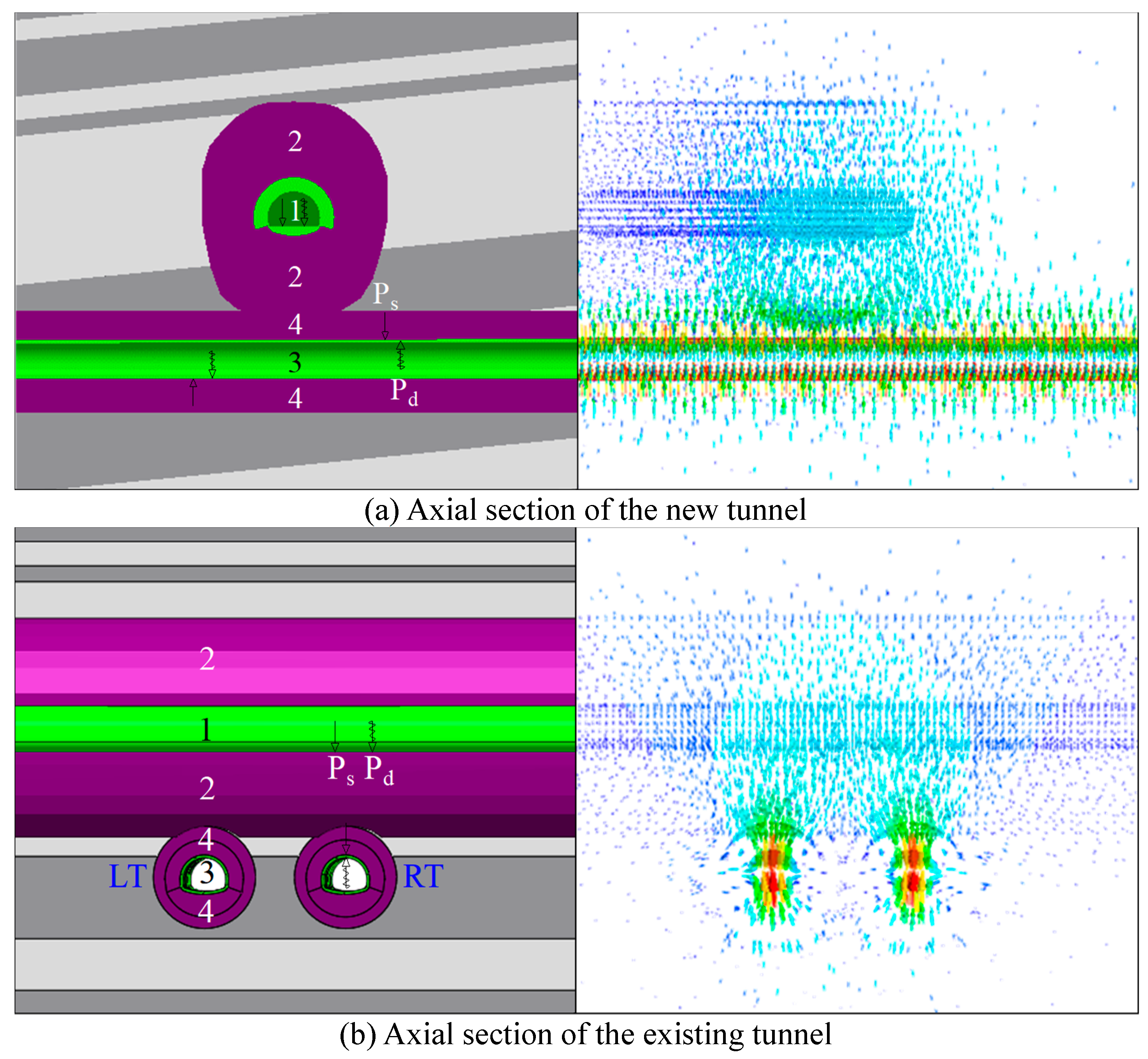
Excavation of the tunnel underneath causes stress release in the rock strata, and the deformation and stress are transmitted to the existing tunnel structure through the rock strata, inducing settlement. The condition of the rock layer where the tunnel is located and its excavation method are the controlling factors for the construction of the new tunnel and the deformation of the existing tunnel structure. Repeated dynamic and static loads from trains running in existing tunnels for a long period of time induce the deterioration of the mechanical parameters of the rock layer in which the tunnel is located, which is a secondary factor causing the deformation of the existing structure. Under the dynamic and static loads of the tunnel excavation and the existing tunnel trains, the stresses and deformations of the rock strata and the existing tunnel structure in the affected areas of the tunnel and the crossover tunnel project are dynamic changes. The mechanical properties of the rock strata in the influence area of the cross-tunneling project are affected by the repeated unloading and loading of the dynamic and static excavation loads, and the repeated dynamic and static train loads. The underpass tunnel, the rock layer in the influence area of the cross-tunneling project, and the existing tunnel structure constitute a multi-structure, multi-factor interaction system, as shown in
Figure 1. Therefore, it is necessary to consider the stiffness of the existing tunnel, the stiffness of the new tunnel, the excavation method load and the existing tunnel load and other factors.
At present, domestic and foreign research, although considerable progress has been made, but the results are mainly concentrated in the subway shield excavation, single-line drilling and blasting method of excavation under the project, for the two-lane large cross-section highway tunnels diagonally under the existing railroad tunnel project not many research cases; the dynamic and static loads in the excavation process of the new tunnels, dynamic and static loads of the existing tunnels are mostly analyzed individually, and the results of the synergistic analysis need to be perfected. In view of this, the stiffness of the existing tunnels is equated by the local layer method; the influence of the underpass first excavated tunnel on settlement is optimized by the correction factor of the influence of the structural stiffness of the existing tunnel on the width of the settlement tank; the degradation of the rock parameters in the influence area of the cross-tunneling project based on the Hoek-Brown criterion characterizes the extent of the influence of the excavation method and dynamic and static loads. A theoretical model for prediction of excavation deformation of a two-lane highway tunnel underneath an existing railroad tunnel coupled with Peck by the multifactor when layer method is proposed.
2. Calculation Method
2.1. Peck Model for Predicting Settlement of Existing Tunnel Structures in under Tunnel Excavation
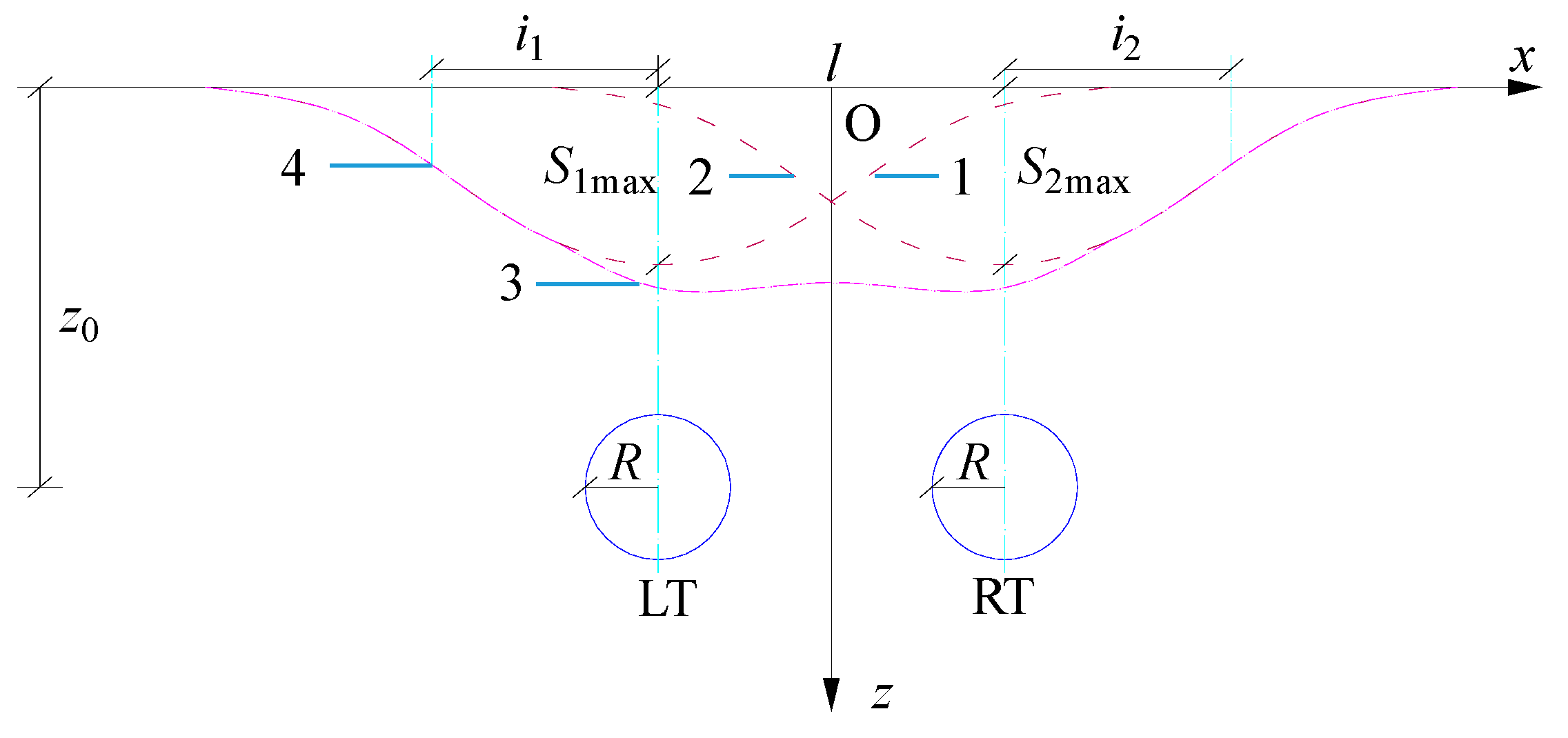
The surface settlement curve caused by the excavation of the two-lane tunnel is shown in
Figure 2 [
15], 1 is the surface settlement curve caused by the excavation of the left-lane tunnel (LT), 2 is the surface settlement curve caused by the excavation of the right-lane tunnel (RT), 3 is the surface settlement curve caused by the superposition of the two-lane tunnel excavation, and 4 is the inflection point of the curve.
The Peck curve equation for surface settlement in a two-lane parallel tunnel excavation is:
Where:
A1 and
A2 are the cross-sectional area of the twin tunnels;
V1 and
V2 are the rate of stratum loss caused by the construction of the twin tunnels;
i1 and
i2 are the respective widths of the sinkholes of the twin tunnels; and
l is the spacing between the centers of the twin tunnels.
Mair [
16] et al. corrected the width of sinkholes to obtain expressions for calculating the width of sinkholes
i at different depths
z locations:
Where
K is the width coefficient of the sinkhole and
z0 is the excavation tunnel burial depth.
R.B. Peck [
14] proposed the formula for
K:
Where:
n is the adjustment factor,
n = 0.8 to 1.0.
Zhou [
18] et al. concluded that the deformation of existing tunnels can be predicted using Peck's formula with corrected ground loss rate and sinkhole width coefficient.
Where:
Vet is the stratum loss rate of the settlement curve of the existing tunnel;
λ𝛼 is the geometric correction coefficient of the angle between the existing tunnel and the new tunnel on the stratum loss rate of the settlement channel,
λ𝛼 =1 /
cos𝛼,
𝛼 is the angle between the new tunnel and the existing tunnel;
λg is the discount factor for the rate of stratum loss by the construction protection measures of the existing tunnel (value range 0 to 1.0).
Where:
Ket is the coefficient of the width of the settlement channel of the existing tunnel;
ηd is the correction coefficient considering the influence of the depth of the existing tunnel on the width of the settlement channel, η
d =[1 -
a (
z /
z0)] / (1 -
z /
z0 ),
a is the parameter considering the lithological condition of the ground layer (the range of values is 0~1);
ηm is the correction coefficient considering the influence of the structural stiffness of the existing tunnel on the width of the settlement channel (the range of values is 1.05~1.6),
ηm = 0.7
M 0.20,
M is the shear stiffness of the existing tunnel section.
Settlement calculation formula for single-line tunnel with diagonal intersection underneath the existing tunnel:
Settlement calculation formula for a two-lane tunnel crossing diagonally under an existing tunnel:
Where:
iet is the width of the sinkhole of the existing tunnel,
iet =
Ket(
z0 -
z);
let is the diagonal spacing of the two-lane tunnel along the direction of the existing tunnel,
let =
l / sin𝛼.
2.2. Theory of Multi-Level Equivalent Layer Method Conversion
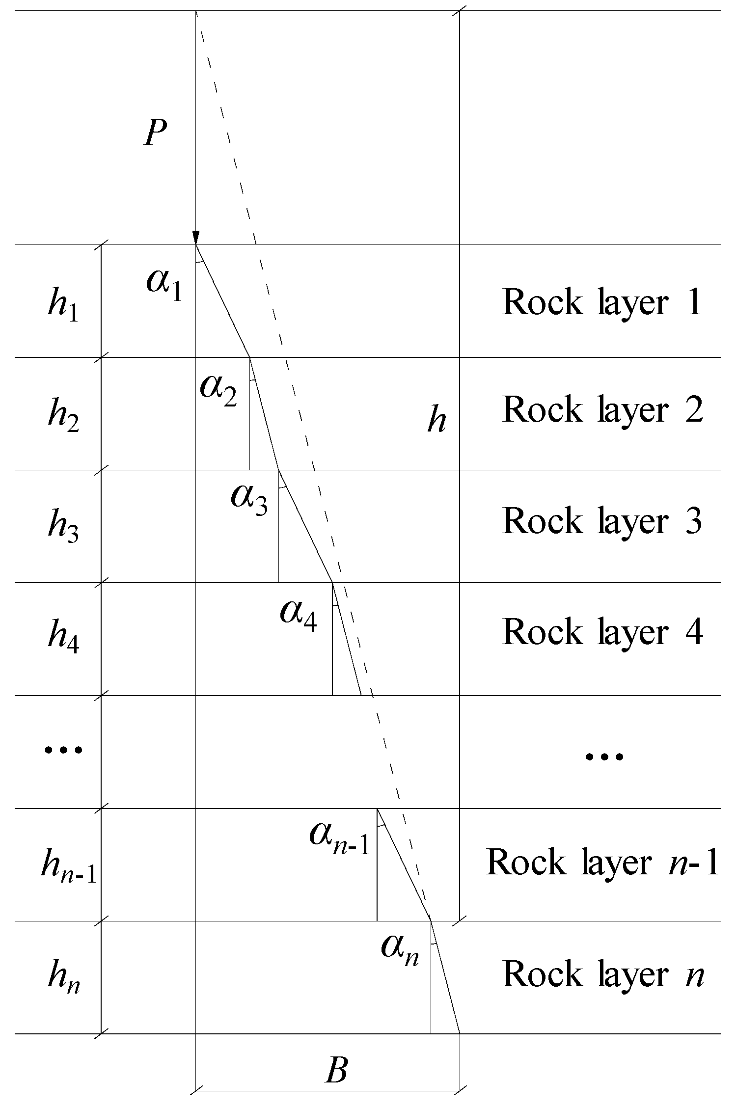
Figure 3 shows the schematic diagram of the conversion calculation of the layer method for the multi-layer geotechnical materials with different properties over the tunnel. The thickness of the
i layer is
hi, the modulus of elasticity is
Ei, Poisson's ratio is
μi, density is
ρi, and the propagation path of vibration wave under the action of concentrated force
P is shown in
Figure 3.
The vibration wave propagates in the first rock layer at a small angle of 𝛼1 with respect to the vertical direction, refracts at the upper interface of the second rock layer, propagates in the second rock layer at a small angle of 𝛼2 with respect to the vertical direction, refracts once at the interface of the rock layers of each of the two layers, and propagates in the i layer at the refraction angle 𝛼i.
The vibrating wave is at a depth
hn in the
n rock layer, then:
The equivalent transformation of each rock layer with different properties into the same rock layer with a vertical distance of (
h +
hn) width of
B.
h is the sum of the equivalent thicknesses of the 1~
n-1 layers.
B is:
According to equations (8) and (9):
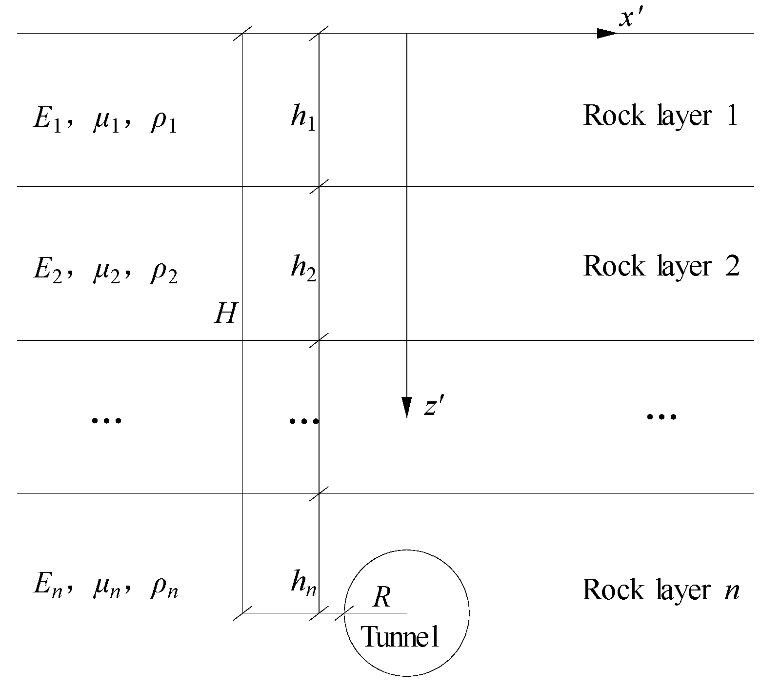
Let the coordinates of any position of the actual stratum be (
xʹ ,
zʹ),
xʹ is the horizontal distance of the position from the tunnel axis, and
zʹ is the vertical distance of the position from the ground surface, as shown in
Figure 4. Through the theory of the current layer method, other geotechnical materials with different properties overlying the tunnel are converted to the same properties as those of the geotechnical layer where the tunnel is located, and the converted coordinates are (
x ,
z).
Perform coordinate conversion:
By coordinate transformation, the problem is transformed into a problem of solving a deformed analytical solution in a homogeneous stratum.
2.3. Structural Deformation Prediction Model for Existing Tunnels When Layer Method-Peck Coupling Is Used
2.3.1. Equivalent Transformation of the Rock Layer Method for Multifactors
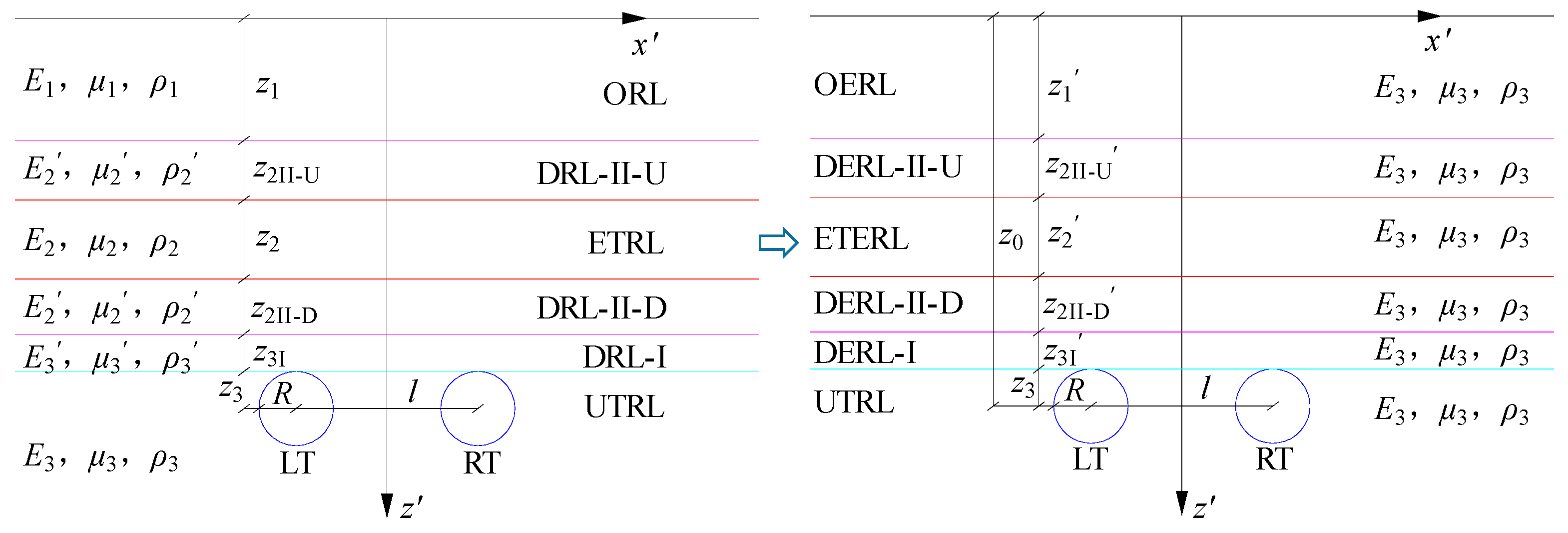
Figure 5 shows the schematic diagram of the equivalent conversion of the cross tunnel project rock layer by the area equivalence method. Assuming that the existing tunnel is converted to a circular diameter of
z2 by the area equivalence method, it is equivalent to a rock layer of the same thickness with the same flexural rigidity (ETRL), and the modulus of elasticity, Poisson's ratio, and density of the equivalent rock layer are
E2,
μ2, and
ρ2, respectively. the modulus of elasticity, Poisson's ratio, and density of the rock layer where the tunnel is underneath (UTRL) are
E3,
μ3, and
ρ3, respectively, with the height of
z3. The modulus of elasticity, Poisson's ratio and density of the rock layer in the area affected by dynamic and static loads (DRL-I) are
E3ʹ,
μ3ʹ,
ρ3ʹ, and the height is
z3I; the modulus of elasticity, Poisson's ratio and density of the rock layer in the area affected by dynamic and static loads in the existing tunnels (DRL-II) are
E2ʹ,
μ2ʹ, and
ρ2ʹ, and the heights of the upper rock layer (DRL-II-U) and the lower one (DRL-II-D) are
z2II-U.The height of the upper rock layer (DRL-II-D) is
z2II-D. The modulus of elasticity, Poisson's ratio, and density of the rock layer overlying the existing tunnel (ORL) are
E1,
μ1, and
ρ1, respectively, and the height of the ORL is
z1.
Based on the principle of the current layer method, the overlying rock layer of the existing tunnel, the rock layer of the dynamic and static load influence area of the cross-tunneling project, and the rock layer of the following tunnel (UTRL) as the current layer are equivalently transformed into mean rock layers, as shown in
Figure 5. The height of the transformed overlying equivalent rock layer (OERL) is
z1ʹ, the height of the upper equivalent rock layer in the area of dynamic and static load influence of the existing tunnels (DERL-II-U) is
z2II-Uʹ, the height of the lower equivalent rock layer in the area of dynamic and static load influence of the existing tunnels (DERL-II-D) is
z2II-Dʹ, and the height of the equivalent rock layer in the existing tunnels (ETERL) is
z2ʹ, and the height of the lower tunnel The height of the equivalent rock layer (DERL-I) in the area affected by the excavation method and static and dynamic loads is
z3Iʹ. The coordinates of the equivalent transformed rock layer using the local layer method are set as (
x,
z) and the coordinates are as follows:
2.3.2. Modification of Peck's Prediction Model under Multifactorial
The transformed equivalent coordinate relationship Eq. (13) is combined with Peck's formula for settlement calculation of two-lane tunnel diagonally intersecting underneath an existing tunnel to form a theoretical model for prediction of deformation in excavation of two-lane highway tunnel underneath an existing railroad tunnel by multifactorial when-layer method coupled with Peck, as detailed in Eq. (14).
By adjusting the correction factor ηm for the effect of the structural stiffness of the existing tunnel on the width of the sinkhole, the difference in the structural settlement of the existing tunnel caused by the underpassing of the left and right tunnels is optimized.
3. Results and Discussion
3.1. Project Examples and Parameter Values
Taking the twin-lane Wanshoushan road tunnel under the Hurong Wanshoushan railroad tunnel project as the background [
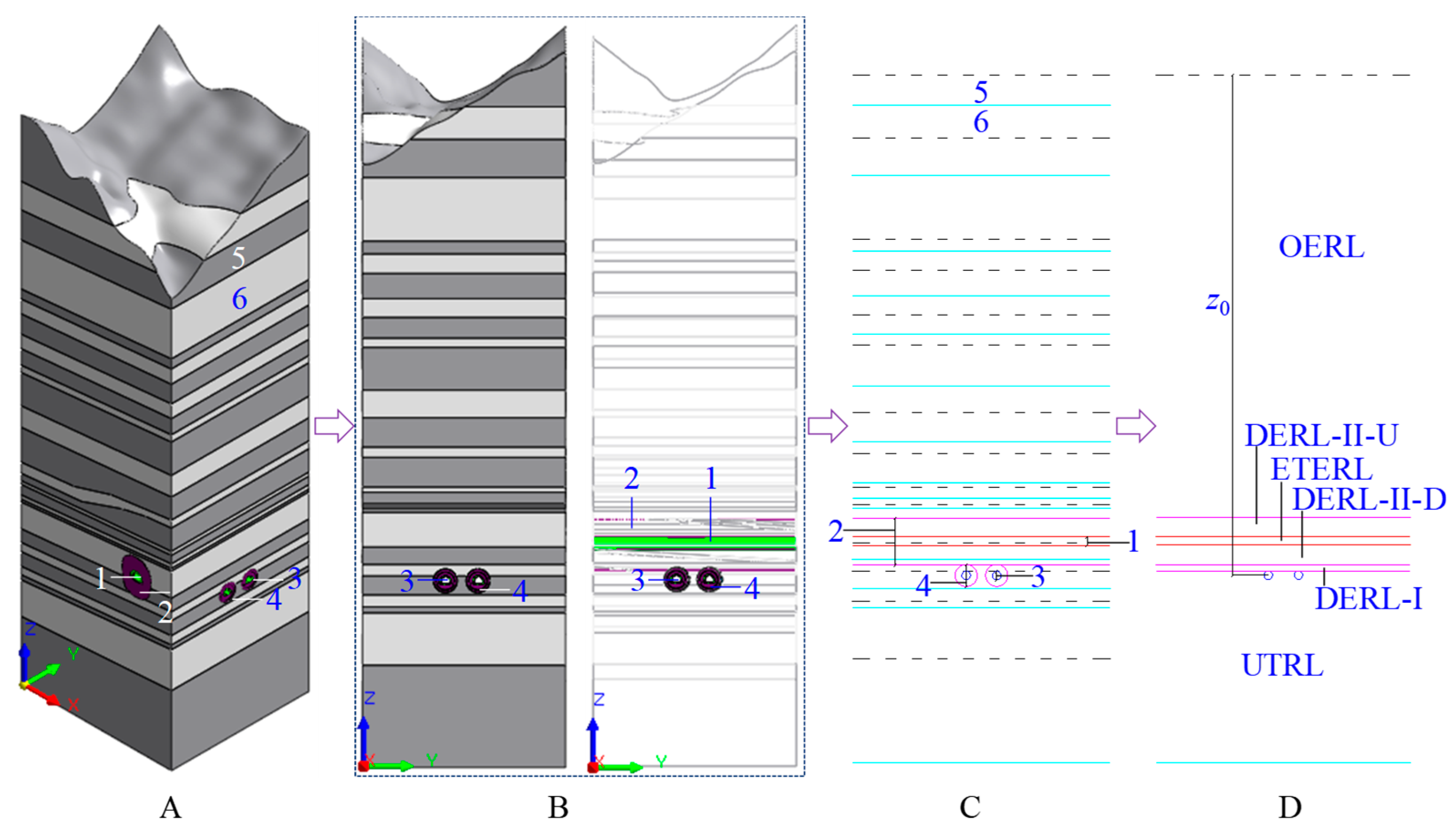
37], the spatial relationship between the underpassing twin-lane tunnel and the existing tunnel and its rock formation are shown in
Figure 6.
(1) Calculation of equivalent modulus of elasticity and density parameters for existing tunnels
The cross-tunnel structure consists of initial and secondary lining supports, whose combined modulus of elasticity
and density
are calculated by Eqs. (15) and (16), and the equivalent modulus of elasticity E and density of the rock layer are calculated by Eqs. (17) and (18).
Where:
is the thickness of initial support,
is the thickness of secondary lining,
is the modulus of elasticity of initial support,
is the modulus of elasticity of secondary lining,
D is the equivalent diameter of the tunnel excavation,
Dʹ is the equivalent diameter of the net section after tunnel support,
is the density of the initial support,
is the density of secondary lining,
R is the equivalent radius of the tunnel excavation,
Rʹ is the equivalent radius of the net section after tunnel support.
The excavated area of the existing tunnel is 124.98m
2 , the clear area is 99.49m
2 , and the radius is 6.31m and 5.63m according to the area equivalent; the excavated area of the new tunnel is 110.31m
2 , the clear area is 76.85m
2 , and the radius is 5.93m and 4.95m according to the area equivalent; the thickness of the initial support of the existing tunnel is 23cm, and the thickness of the secondary lining is 45cm;the thickness of initial support of the new tunnel is 28cm, and the thickness of secondary lining is 70cm; the corresponding modulus of elasticity and density parameters are taken from the literature [
37], and the modulus of elasticity of the equivalent rock layer of the existing tunnel is 8.51 GPa and the density is 5.19 kN.m
-3 according to the equations (16)~(17).
(2) Parameters related to equivalent rock transformation in cross tunnels
The double-lane Wanshoushan Highway Tunnel under the Hurong Wanshoushan Railway Tunnel Project is a mudstone and Malmstone interbedded rock layer, the new tunnel is located in the rock layer and the height of the overburden rock layer information is shown in
Table 1, the mechanical parameters of the rock layer are taken from the literature [
37]. The mudstone where the lower tunnel is located is the current layer, and the theoretical method proposed in the previous section is used to transform the Malmstone and the existing tunnel into the current layer, with the current layer index
a of 0.33. The height of the dynamic and static loading zone of the existing and new tunnels is based on literature [
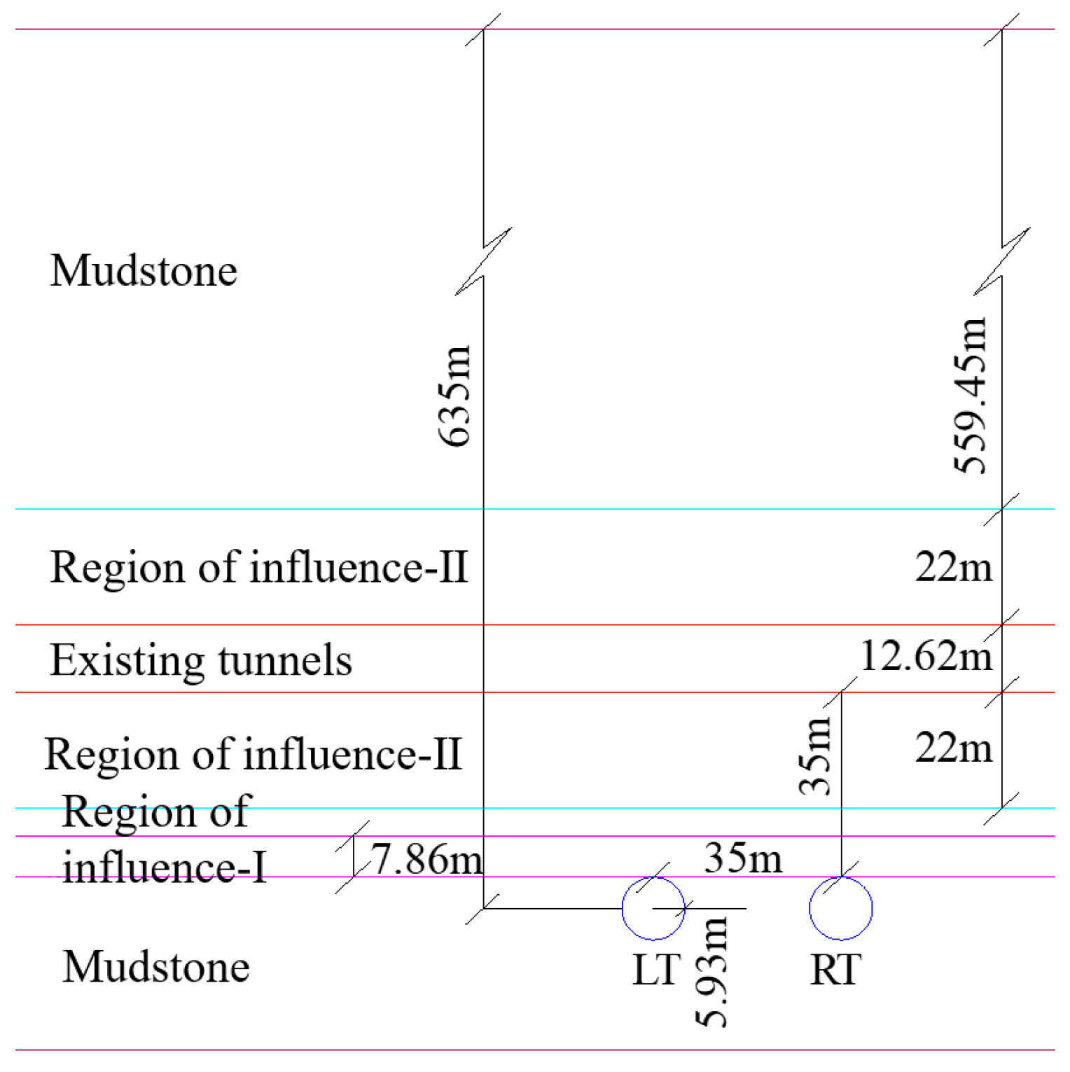
37], ignoring the width of the overlapping zone of influence. The relationship between the layers considering the stiffness of the existing tunnel and the dynamic and static loads of the cross-tunnel project is shown in
Figure 7. The modulus of elasticity and density parameters of each rock layer considering the effects of dynamic and static loading of the existing tunnel and the cross-tunneling project are shown in
Table 2, and the parameters of the influence area are taken from the results of the literature [
38].
Combined with
Figure 8 and
Table 2 data, using the theoretical method proposed in the previous section of the existing tunnel, the impact of the regional rock layer when the layer occurs to transform the calculation, when the layer of the index
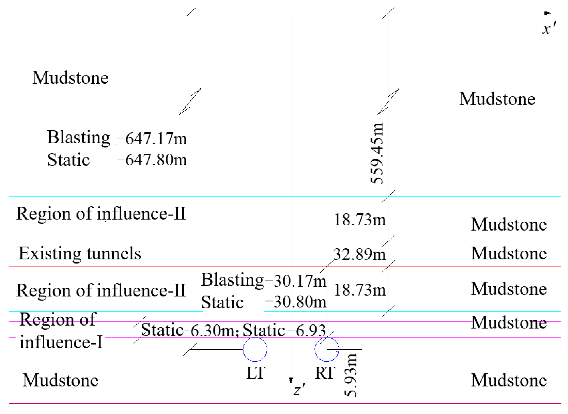
a to take 0.33. Derived from the consideration of the stiffness of the existing tunnel and the cross-tunnel engineering dynamic and static load impact of the rock layer when the layer of the relationship, such as shown in
Figure 8. New tunnel depth: 647.17m (blasting method excavation), 647.80m (static method excavation), cross tunnel spacing: 30.17m (blasting method excavation), 30.80m (static method excavation).
3.2. Theoretical Calculation Results
In the project example, the angle between the new tunnel and the existing tunnel is 61°, 𝛼 = 61° [
37].The parameters related to formula (2) ~ (7) of the Peck settlement formula are optimized by the numerical calculation results, which are shown in
Figure 9, and the parameters related to the calculation of the settlement of the base plate of the existing tunnel for different working conditions are finally determined as shown in
Table 3. Only
ηm is different for the left and right lines of the same working condition, and the other parameters take the same value.
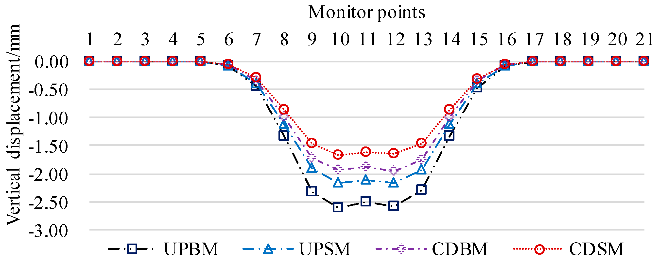
Substitute the parameters of
Table 3 into Eqs. (2) to (7) to get the settlement value of Peck's bottom plate of existing tunnels under different calculation conditions, and extract the values of the monitoring points corresponding to the numerical simulation settlement curves to generate the settlement curves as shown in
Figure 10.
3.3. Comparison and Optimization
(1) Comparison and optimization of numerical and theoretical calculations
Comparing the results of numerical simulation and theoretical calculation for different calculation conditions, the error between the two is mainly caused by the phenomenon of overall uniform settlement of the existing tunnel floor during numerical calculation, based on this phenomenon, Eq. (7) is optimized by increasing the value of overall settlement
Sos, and the revised formula for calculating the Peck settlement of the existing tunnel floor is as follows:
Overall settlement
Sos values, determined by numerical calculations and field monitoring data. In this chapter, the
Sos values are determined by numerical calculation results, and the
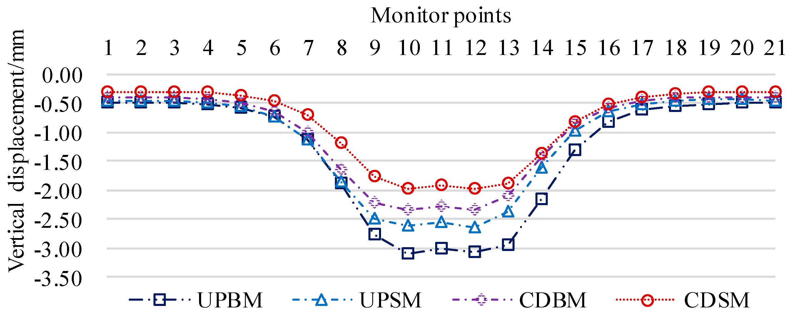
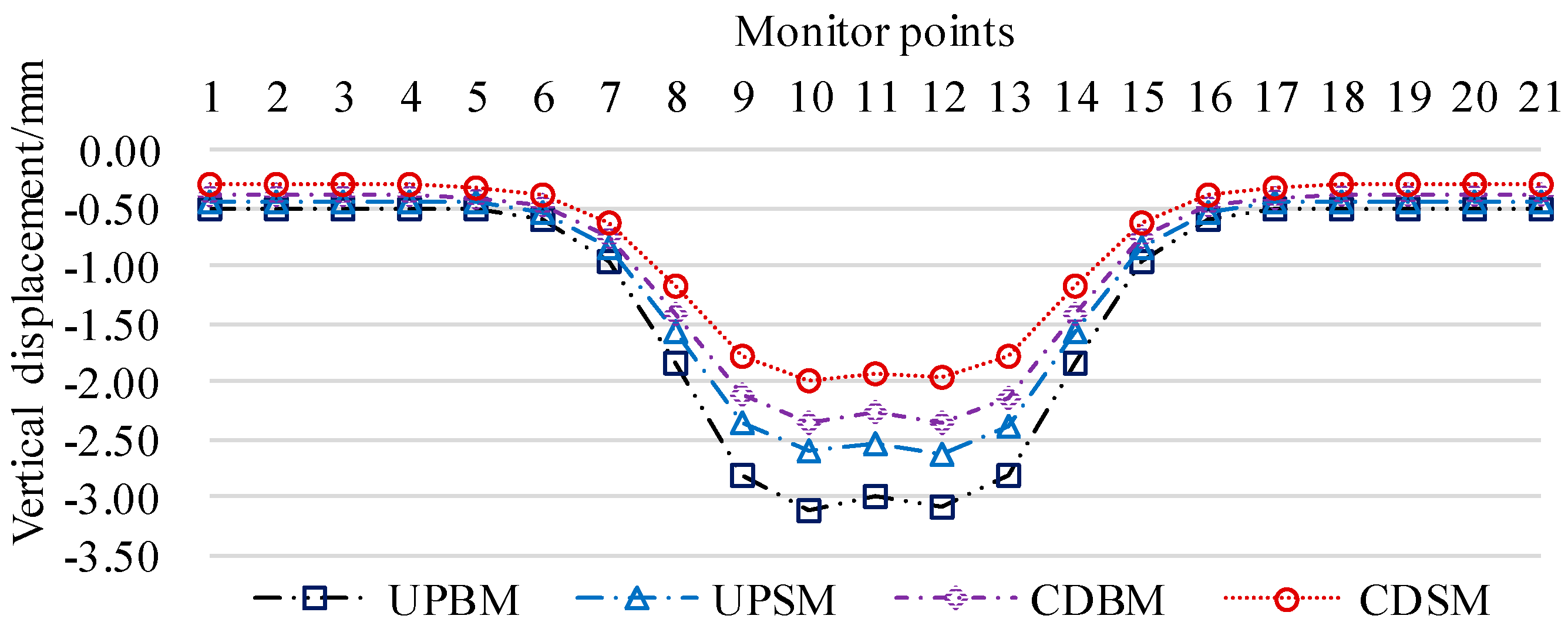
Sos is 0.50mm for UPBM working condition, 0.45mm for UPSM working condition, 0.40mm for CDBM working condition, and 0.31mm for CDSM working condition.The calculated curves of the modified Peck settlement for the base plate of the existing tunnel for different working conditions are shown in
Figure 11.
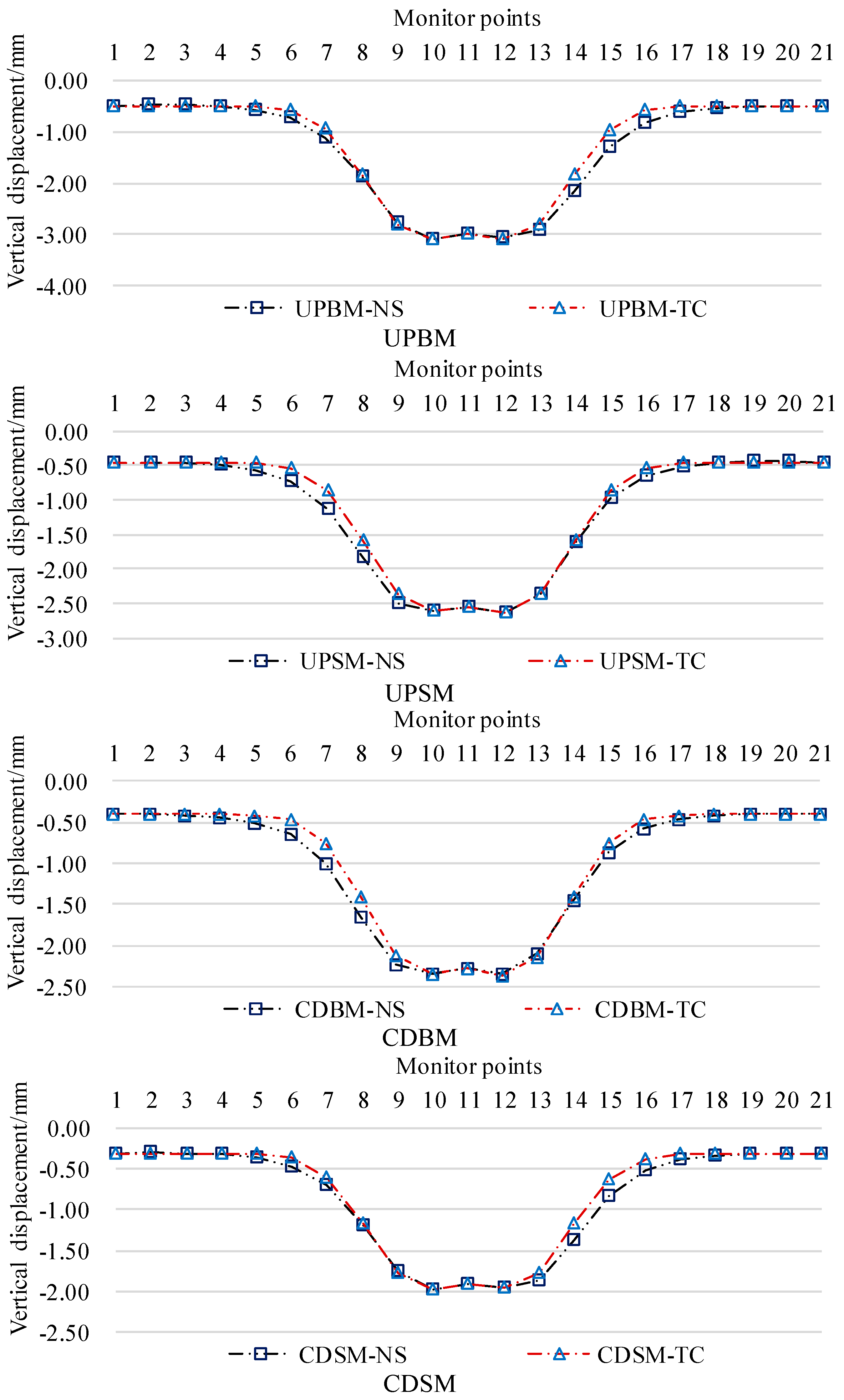
The data comparison is based on the numerical calculation result data, as shown in
Figure 12. The data error of the maximum value of the four calculation conditions is less than 5%, and the data error of the inflection point area is less than 15%, which indicates that the settlement of the base plate of the existing tunnel is in accordance with the Peck settlement calculation formula.
(2) Monitoring data and theoretical calculations compared to verify
Project examples of the new tunnel left and right lines and the existing tunnel crossing point before and after the 60m excavation section process, the existing tunnel floor settlement monitoring. Existing tunnel settlement monitoring points are arranged at the root of the left wall of the existing tunnel, the following through the center line of the double tunnel and the left wall of the existing tunnel line intersection for the center line to the left, right every 10m, set up settlement monitoring points, a total of 27 measuring points, a total length of 260m.
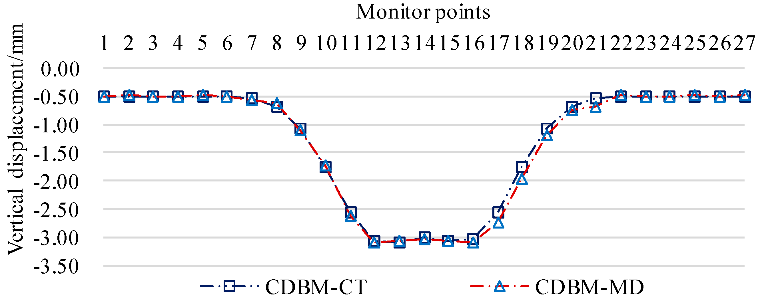
In order to facilitate the comparison and verification, using the modified Peck settlement formula for the base plate of the existing tunnel, the settlement curve of the base plate of the existing tunnel at 10m intervals (CDBM-CT) is derived, and the comparison with the settlement monitoring curve of the existing tunnel (CDBM-MD) is shown in
Figure 13. The error of the extreme value data is less than 3%, and the error of the data in the inflection point area is less than 14%, which verifies that the modified theoretical model of Peck settlement calculation can predict the excavation deformation of double-lane highway tunnels underneath the existing railroad tunnels more accurately.
4. Conclusions
(1) Based on the theory of the current layer method, factors such as the stiffness of the existing tunnel, the stiffness of the new tunnel, the load of the excavation method and the load of the existing tunnel are introduced, and by adjusting the correction coefficient ηm for the influence of the structural stiffness of the existing tunnel on the width of the sinkhole to optimize the difference in the structural settlement of the existing tunnel caused by the tunnel passing through the left and right tunnels, the theoretical model for predicting deformation of the tunnel excavation of a two-lane highway tunnel passing under the existing railroad under the current layer method coupled with the Peck method with multi-factors is constructed. Deformation prediction theoretical model.
(2) Considering the overall uniform settlement of the existing tunnel floor, the overall settlement Sos parameter is added, and the modified Peck settlement formula for the existing tunnel floor is proposed.
(3) The Peck settlement formula was corrected by numerical calculation, and the field monitoring data were compared with the corrected Peck settlement formula, and the error of the extreme value data was less than 3%, and the error of the data in the inflection point area was less than 14%, which verified the validity of the corrected theoretical model of Peck settlement calculation.
Author Contributions
Methodology, Y.L.; Formal analysis, Y.L., C.H. and H.L.; Resources, C.H.; Data curation, C.H., H.L. and C.M.; Writing—original draft, C.H., H.L. and C.M.; Writing—review & editing, H.L. and C.M.; Visualization, C.H., H.L. and C.M.; Funding acquisition, Y.L. All authors have read and agreed to the published version of the manuscript.
Funding
This work is supported by the Hongjian Lu: Natural Science Foundation of Hebei Province (No. E2021209006).
Institutional Review Board Statement
Not applicable.
Informed Consent Statement
Not applicable.
Data Availability Statement
Data sharing is not applicale.
Conflicts of Interest
The authours declare no conflict of interest.
References
- CHEN Z L, CHEN J Y, LIU H, et al. Present status and development trends of underground space in Chinese cities: Evaluation and analysis [J]. Tunnelling and Underground Space Technology, 2018, 71: 253-70.
- LIU S C, PENG F L, QIAO Y K, et al. Quantitative evaluation of the contribution of underground space to urban resilience: A case study in China [J]. Underground Space, 2024, 17: 1-24.
- FANG Q, LIU X, ZENG K H, et al. Centrifuge modelling of tunnelling below existing twin tunnels with different types of support [J]. Underground Space, 2022, 7(6): 1125-38.
- DENG H S, FU H L, YUE S, et al. Ground loss model for analyzing shield tunneling-induced surface settlement along curve sections [J]. Tunnelling and Underground Space Technology, 2022, 119.
- JIANG S, HUANG M, WANG B N, et al. Numerical study on the effects of wetting-drying cycles on the failure characteristics of tunnels excavated in gypsiferous strata based on discrete element method [J]. Bulletin of Engineering Geology and the Environment, 2023, 82(9).
- WU L L, HE K Q, GUO L, et al. Research on the excavation stability evaluation method of Chaqishan ancient landslide in China [J]. Engineering Failure Analysis, 2022, 141.
- ZHENG G, YANG X Y, ZHOU H Z, et al. A simplified prediction method for evaluating tunnel displacement induced by laterally adjacent excavations [J]. Computers and Geotechnics, 2018, 95: 119-28.
- SUN H S, CHEN Y D, ZHANG J H, et al. Analytical investigation of tunnel deformation caused by circular foundation pit excavation [J]. Computers and Geotechnics, 2019, 106: 193-8.
- CHENG H Z, CHEN R P, WU H N, et al. A simplified method for estimating the longitudinal and circumferential behaviors of the shield-driven tunnel adjacent to a braced excavation [J]. Computers and Geotechnics, 2020, 123.
- CHEN F Y, WANG L, ZHANG W G. Reliability assessment on stability of tunnelling perpendicularly beneath an existing tunnel considering spatial variabilities of rock mass properties [J]. Tunnelling and Underground Space Technology, 2019, 88: 276-89.
- CHEN R P, ZHANG P, WU H N, et al. Prediction of shield tunneling-induced ground settlement using machine learning techniques [J]. Frontiers of Structural and Civil Engineering, 2019, 13(6): 1363-78.
- CHENG L Y, ARIARATNAM S T, CHEN S X. Analytical Solution for Predicting Ground Deformation Associated with Pipe Jacking [J]. Journal of Pipeline Systems Engineering and Practice, 2017, 8(3).
- CHOO C S, ONG D E L. Assessment of non-linear rock strength parameters for the estimation of pipe-jacking forces. Part 2. Numerical modeling [J]. Engineering Geology, 2020, 265.
- ZHOU Z, DING H H, MIAO L W, et al. Predictive model for the surface settlement caused by the excavation of twin tunnels [J]. Tunnelling and Underground Space Technology, 2021, 114.
- KONG F C, LU D C, DU X L, et al. Analytical solution of stress and displacement for a circular underwater shallow tunnel based on a unified stress function [J]. Ocean Engineering, 2021, 219.
- MAIR R J, TAYLOR R N, BRACEGIRDLE A. SUBSURFACE SETTLEMENT PROFILES ABOVE TUNNELS IN CLAYS [J]. Geotechnique, 1993, 43(2): 315-20.
- LIN C G, HUANG M S. Tunnelling-induced response of a jointed pipeline and its equivalence to a continuous structure [J]. Soils and Foundations, 2019, 59(4): 828-39.
- ZHOU Z, CHEN Y, LIU Z Z, et al. Theoretical prediction model for deformations caused by construction of new tunnels undercrossing existing tunnels based on the equivalent layered method [J]. Computers and Geotechnics, 2020, 123.
- VORSTER T E B, KLAR A, SOGA K, et al. Estimating the effects of tunneling on existing pipelines [J]. Journal of Geotechnical and Geoenvironmental Engineering, 2005, 131(11): 1399-410.
- MARSHALL A M, KLAR A, MAIR R J. Tunneling beneath Buried Pipes: View of Soil Strain and Its Effect on Pipeline Behavior [J]. Journal of Geotechnical and Geoenvironmental Engineering, 2010, 136(12): 1664-72.
- SAGASETA C. ANALYSIS OF UNDRAINED SOIL DEFORMATION DUE TO GROUND LOSS [J]. Geotechnique, 1987, 37(3): 301-20.
- VERRUIJT A, BOOKER J R. Surface settlements due to deformation of a tunnel in an elastic half plane [J]. Geotechnique, 1996, 46(4): 753-6.
- LOGANATHAN N, POULOS H G. Analytical prediction for tunneling-induced ground movements in clays [J]. Journal of Geotechnical and Geoenvironmental Engineering, 1998, 124(9): 846-56.
- LI P, DU S J, SHEN S L, et al. Timoshenko beam solution for the response of existing tunnels because of tunneling underneath [J]. International Journal for Numerical and Analytical Methods in Geomechanics, 2016, 40(5): 766-84.
- LIU B, YU Z W, ZHANG R H, et al. Effects of Undercrossing Tunneling on Existing Shield Tunnels [J]. International Journal of Geomechanics, 2021, 21(8).
- SHI J W, LIU G B, HUANG P, et al. Interaction between a large-scale triangular excavation and adjacent structures in Shanghai soft clay [J]. Tunnelling and Underground Space Technology, 2015, 50: 282-95.
- JIANG D, LI Y B, FEI Q G, et al. Prediction of uncertain elastic parameters of a braided composite [J]. Composite Structures, 2015, 126: 123-31.
- AVRAMIDIS I E, MORFIDIS K. Bending of beams on three-parameter elastic foundation [J]. International Journal of Solids and Structures, 2006, 43(2): 357-75.
- HONG T, TENG J G, LUO Y F. Axisymmetric shells and plates on tensionless elastic foundations [J]. International Journal of Solids and Structures, 1999, 36(34): 5277-300.
- WANG L L, ISHIHARA T. A study of the effects of foundation uplift on the seismic loading of wind turbine tower and shallow foundation using a new dynamic Winkler model [J]. Engineering Structures, 2020, 219.
- KLAR A, VORSTER T E B, SOGA K, et al. Soil-pipe interaction due to tunnelling: comparison between Winkler and elastic continuum solutions [J]. Geotechnique, 2005, 55(6): 461-6.
- LIU D J, TIAN C, WANG F, et al. Longitudinal structural deformation mechanism of shield tunnel linings considering shearing dislocation of circumferential joints [J]. Computers and Geotechnics, 2021, 139.
- ZHANG Z G, HUANG M S. Geotechnical influence on existing subway tunnels induced by multiline tunneling in Shanghai soft soil [J]. Computers and Geotechnics, 2014, 56: 121-32.
- XU Q, LEI S X, ZHU Y Q, et al. Theoretical prediction model for surface settlement caused by the excavation of new tunnels undercrossing existing tunnels based on modified stochastic medium theory [J]. Ksce Journal of Civil Engineering, 2022, 26(9): 4136-45.
- XU Q, ZHU Y Q, LEI S X, et al. A simplified 3d theoretical model for calculating the surface settlement induced by tunnel undercrossing excavation [J]. International Journal of Geomechanics, 2023, 23(10).
- ZHOU Z, ZHENG Y D, HU J F, et al. Deformation analysis of shield undercrossing and vertical paralleling excavation with existing tunnel in composite stratum [J]. Journal of Central South University, 2023, 30(9): 3127-44.
- LI Y F, HUANG C F, LU H J, et al. Investigation of the influence area of the excavation of a double-line highway tunnel under an existing railway tunnel [J]. Applied Sciences-Basel, 2024, 14, 290.
- LI Y F, HUANG C F, LU H J, et al. Investigation on the mechanical characteristics of excavation of double-line highway tunnel underpass existing railway tunnel under the influence of dynamic and static load [J]. Applied Sciences-Basel, 2024,14,3242.
Figure 1.
Schematic diagram of the location of the overlying multi-layered geotechnical layers of the tunnel: 1 is the existing tunnel structure, 2 is the area of the rock layer affected by the dynamic and static loads of the existing tunnel, 3 is the structure of the tunnel underneath, 4 is the area affected by the dynamic and static loads of the tunnel excavation underneath, Ps is the static load, and Pd is the dynamic and static load.
Figure 2.
Peck Prediction Curve for Surface Settlement in Two-Lane Tunnel Excavation.
Figure 2.
Peck Prediction Curve for Surface Settlement in Two-Lane Tunnel Excavation.
Figure 3.
Multiple layers of geotechnical materials with different properties overlying the tunnel.
Figure 3.
Multiple layers of geotechnical materials with different properties overlying the tunnel.
Figure 4.
Schematic diagram of the location of the multi-layered soil and rock layers overlying the tunnel.
Figure 4.
Schematic diagram of the location of the multi-layered soil and rock layers overlying the tunnel.
Figure 5.
Schematic diagram of the equivalent transformation of the rock layer method for cross-tunneling projects.
Figure 5.
Schematic diagram of the equivalent transformation of the rock layer method for cross-tunneling projects.
Figure 6.
Spatial relationship and rock layer diagram of the underpassing two-lane tunnel and the existing tunnel: A is the three-dimensional spatial relationship, B is the X-direction side view, C is the two-dimensional rock layer and spatial relationship, and D is the spatial relationship transformed by the layer method, 1 is the structure of the existing tunnel, 2 is the dynamic and static load influence area of the existing tunnel, 3 is the structure of the underpassing tunnel, 4 is the dynamic and static load influence area of the excavation of the underpassing tunnel, 5 is the mudstone, and 6 is the Malmstone.
Figure 7.
Relationship between the rock strata considering the effect of the stiffness of the existing tunnel and the dynamic and static loads of the cross-tunneling project.
Figure 7.
Relationship between the rock strata considering the effect of the stiffness of the existing tunnel and the dynamic and static loads of the cross-tunneling project.
Figure 8.
Stratigraphy of the rock layers taking into account the effect of the stiffness of the existing tunnel and the static and dynamic loads of the cross-tunneling project.
Figure 8.
Stratigraphy of the rock layers taking into account the effect of the stiffness of the existing tunnel and the static and dynamic loads of the cross-tunneling project.
Figure 9.
Displacement and settlement curves of the existing tunnel base plate under different calculation conditions.
Figure 9.
Displacement and settlement curves of the existing tunnel base plate under different calculation conditions.
Figure 10.
Calculation curves of Peck's settlement at monitoring points of existing tunnel base plate under different calculation conditions.
Figure 10.
Calculation curves of Peck's settlement at monitoring points of existing tunnel base plate under different calculation conditions.
Figure 11.
Modified Peck Settlement Calculation Curve for Existing Tunnel Base Plate Monitoring Points under Different Calculation Conditions.
Figure 11.
Modified Peck Settlement Calculation Curve for Existing Tunnel Base Plate Monitoring Points under Different Calculation Conditions.
Figure 12.
Comparison of numerical calculations and Peck's theoretical calculations of the settlement of the base plate of existing tunnels under different working conditions.
Figure 12.
Comparison of numerical calculations and Peck's theoretical calculations of the settlement of the base plate of existing tunnels under different working conditions.
Figure 13.
Comparison curve between the settlement monitoring data of the base plate of the existing tunnel and Peck's theoretical calculation data.
Figure 13.
Comparison curve between the settlement monitoring data of the base plate of the existing tunnel and Peck's theoretical calculation data.
Table 1.
X-direction side view 2D rock layer with equivalent rock layer height parameters.
Table 1.
X-direction side view 2D rock layer with equivalent rock layer height parameters.
| Rock layer (top to bottom) |
Height (m) |
Equivalent height (m) |
Remarks |
| Mudstone |
31.6 |
31.6 |
Area equivalent |
| Malmstone |
35.5 |
47.6 |
|
| Mudstone |
41.5 |
41.5 |
|
| Malmstone |
68.9 |
92.3 |
|
| Mudstone |
14.0 |
14.0 |
|
| Malmstone |
21.2 |
28.4 |
|
| Mudstone |
27.3 |
27.3 |
|
| Malmstone |
20.4 |
27.3 |
|
| Mudstone |
22.4 |
22.4 |
|
| Malmstone |
10.0 |
13.4 |
|
| Mudstone |
46.3 |
46.3 |
|
| Malmstone |
30.0 |
40.2 |
|
| Mudstone |
32.0 |
32.0 |
|
| Malmstone |
11.0 |
14.7 |
|
| Mudstone |
32.3 |
32.3 |
|
| Malmstone |
5.6 |
7.5 |
|
| Mudstone |
10.6 |
10.6 |
|
| Malmstone |
7.4 |
9.9 |
|
| Mudstone |
3.9 |
3.9 |
|
| Malmstone |
37.5 |
50.3 |
Existing tunnel formations |
| Mudstone |
18.3 |
18.9 |
|
| Malmstone |
12.1 |
16.6 |
|
| Mudstone |
20.6 |
20.6 |
Rock formation of the lower tunnel |
Table 2.
Formation parameters taking into account the influence of the stiffness of the existing tunnel and the dynamic and static loads of the cross-tunneling project.
Table 2.
Formation parameters taking into account the influence of the stiffness of the existing tunnel and the dynamic and static loads of the cross-tunneling project.
| Rock Stratum |
Modulus of elasticity (GPa) |
Density (kN.m-3) |
| Mudstone |
2.15 |
23.89 |
| Existing Tunnels |
8.51 |
5.19 |
| Impact Area-I (Blasting) |
1.10 |
23.89 |
| Area of Influence-I (Static) |
1.47 |
23.89 |
| Area of Influence-II (Blasting) |
1.32 |
23.89 |
| Area of Influence-II (Static) |
1.32 |
23.89 |
Table 3.
Parameters related to Peck settlement calculation for different working conditions of existing tunnels.
Table 3.
Parameters related to Peck settlement calculation for different working conditions of existing tunnels.
| Working Condition |
z0/m |
z/m |
l/m |
R/m |
n |
λ𝛼
|
λg |
V/% |
ηd |
|
|
| UPBM |
641.17 |
617.00 |
35.00 |
5.93 |
0.99 |
2.06 |
0.20 |
0.230 |
1.06 |
1.06 |
1.05 |
| UPSM |
641.80 |
617.00 |
35.00 |
5.93 |
0.99 |
2.06 |
0.20 |
0.193 |
1.06 |
1.05 |
1.06 |
| CDBM |
641.17 |
617.00 |
35.00 |
5.93 |
0.99 |
2.06 |
0.20 |
0.173 |
1.06 |
1.05 |
1.06 |
| CDSM |
641.80 |
617.00 |
35.00 |
5.93 |
0.99 |
2.06 |
0.20 |
0.148 |
1.06 |
1.06 |
1.05 |
|
Disclaimer/Publisher’s Note: The statements, opinions and data contained in all publications are solely those of the individual author(s) and contributor(s) and not of MDPI and/or the editor(s). MDPI and/or the editor(s) disclaim responsibility for any injury to people or property resulting from any ideas, methods, instructions or products referred to in the content. |
© 2024 by the authors. Licensee MDPI, Basel, Switzerland. This article is an open access article distributed under the terms and conditions of the Creative Commons Attribution (CC BY) license (http://creativecommons.org/licenses/by/4.0/).
