Submitted:
16 April 2024
Posted:
17 April 2024
You are already at the latest version
Abstract
Keywords:
1. Introduction
2. Structure Design and Simulation
3. Metasurface Performance
3.1. Performance of the Multifunctional (SFL) Metasurface as a Polarization Conversion
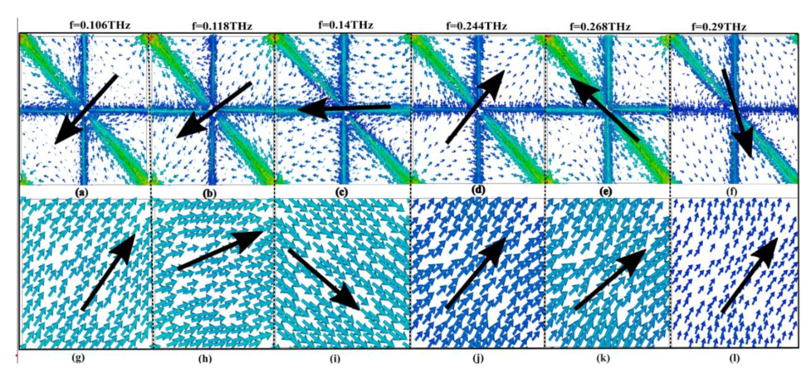
3.2. Performance of the Multifunctional (SFL) Metasurface as an Absorption
5. Conclusions
Author Contributions
Funding
Data Availability Statement
Conflicts of Interest
References
- Ferguson, B. and X.-C. Zhang, Materials for terahertz science and technology. Nature materials, 2002. 1(1): p. 26-33.
- Chen, H.-T., et al., Active terahertz metamaterial devices. Nature, 2006. 444(7119): p. 597-600.
- Grady, N.K., et al., Terahertz metamaterials for linear polarization conversion and anomalous refraction. Science, 2013. 340(6138): p. 1304-1307.
- Zeng, F., et al., Tunable mid-infrared dual-band and broadband cross-polarization converters based on U-shaped graphene metamaterials. Optics Express, 2019. 27(23): p. 33826-33839.
- Lin, R., et al., Multiple interference theoretical model for graphene metamaterial-based tunable broadband terahertz linear polarization converter design and optimization. Optics Express, 2021. 29(19): p. 30357-30370.
- Xu, S., et al., Liquid crystal integrated metamaterial for multi-band terahertz linear polarization conversion. Chinese Optics Letters, 2021. 19(9): p. 093701.
- Li, J., et al., Terahertz wavefront shaping with multi-channel polarization conversion based on all-dielectric metasurface. Photonics Research, 2021. 9(10): p. 1939-1947.
- Jiang, Y., et al., Ultra-wideband high-efficiency reflective linear-to-circular polarization converter based on metasurface at terahertz frequencies. Optics express, 2017. 25(22): p. 27616-27623.
- Tamayama, Y., et al., A linear-to-circular polarization converter with half transmission and half reflection using a single-layered metamaterial. Applied Physics Letters, 2014. 105(2).
- Yue, Z., et al., Manipulation of polarization conversion and multiplexing via all-silicon phase-modulated metasurfaces. Chinese Optics Letters, 2022. 20(4): p. 043601.
- Cheng, Y. and J. Wang, Tunable terahertz circular polarization convertor based on graphene metamaterial. Diamond and Related Materials, 2021. 119: p. 108559.
- Yao, G., et al., Dual-band tunable perfect metamaterial absorber in the THz range. Optics express, 2016. 24(2): p. 1518-1527.
- Sun, P., et al., Graphene-based dual-band independently tunable infrared absorber. Nanoscale, 2018. 10(33): p. 15564-15570.
- Chen, Z., et al., Dual-band perfect absorber for a mid-infrared photodetector based on a dielectric metal metasurface. Photonics Research, 2021. 9(1): p. 27-33.
- Xia, S.-X., et al., Multi-band perfect plasmonic absorptions using rectangular graphene gratings. Optics letters, 2017. 42(15): p. 3052-3055.
- Wu, D., et al., Independently tunable perfect absorber based on the plasmonic properties in double-layer graphene. Carbon, 2019. 155: p. 618-623.
- Jiang, L., et al., Multi-band and high-sensitivity perfect absorber based on monolayer graphene metamaterial. Diamond and Related Materials, 2021. 111: p. 108227.
- Chen, Z., et al., Multi-band multi-tunable perfect plasmon absorber based on L-shaped and double-elliptical graphene stacks. Diamond and Related Materials, 2021. 115: p. 108374.
- Zhu, J., et al., Ultra-broadband terahertz metamaterial absorber. Applied Physics Letters, 2014. 105(2).
- Lei, L., et al., Ultra-broadband absorber from visible to near-infrared using plasmonic metamaterial. Optics express, 2018. 26(5): p. 5686-5693.
- Wang, B., et al., Ultra-broadband nanowire metamaterial absorber. Photonics Research, 2022. 10(12): p. 2718-2727.
- Goldstein, D.H., Polarized light. 2017: CRC press.
- Dorrah, A.H., et al., Metasurface optics for on-demand polarization transformations along the optical path. Nature Photonics, 2021. 15(4): p. 287-296.
- Scully, M.O. and M.S. Zubairy, Quantum optics. 1997: Cambridge university press.
- Demos, S. and R. Alfano, Optical polarization imaging. Applied optics, 1997. 36(1): p. 150-155.
- Holliman, N.S., et al., Three-dimensional displays: a review and applications analysis. IEEE transactions on Broadcasting, 2011. 57(2): p. 362-371.
- Tyo, J.S., et al., Review of passive imaging polarimetry for remote sensing applications. Applied optics, 2006. 45(22): p. 5453-5469.
- Peng, L., et al., A novel THz half-wave polarization converter for cross-polarization conversions of both linear and circular polarizations and polarization conversion ratio regulating by graphene. Journal of Lightwave Technology, 2018. 36(19): p. 4250-4258.
- Guo, Z., et al., A novel reconfigurable metasurface with coincident and ultra-wideband LTL and LTC polarization conversion functions. Radio Engineering, 2019. 28(4): p. 696-702.
- Qiao, Q., et al., Broadband of linear-to-linear and double-band of linear-to-circular polarization converter based on a graphene sheet with a π-shaped hollow array. Optical Materials Express, 2021. 11(9): p. 2952-2965.
- Yan, D., et al., Vanadium dioxide-assisted broadband absorption and linear-to-circular polarization conversion based on a single metasurface design for the terahertz wave. Optics Express, 2020. 28(20): p. 29843-29854.
- Ghosh, S.K., S. Das, and S. Bhattacharyya, Transmittive-type triple-band linear to circular polarization conversion in THz region using graphene-based metasurface. Optics Communications, 2021. 480: p. 126480.
- Qureshi, U.U.R., et al., Design and experimental realization of multifunctional anisotropic metasurface for efficient polarization manipulation in microwave frequencies. Physica Scripta, 2023. 99(1): p. 015512.
- Lin, B., et al., A high efficiency ultra-wideband circular-to-linear polarization conversion metasurface. Optics Communications, 2023. 529: p. 129102.
- Lin, B.-q., et al., Ultra-wideband linear-to-circular and circular-to-linear polarization conversion realized by anisotropic metasurface. Plasmonics, 2022. 17(6): p. 2405-2415.
- Ye, L., et al., Electrically tunable broadband terahertz absorption with hybrid-patterned graphene metasurfaces. Nanomaterials, 2018. 8(8): p. 562.
- Song, Z., Z. Wang, and M. Wei, Broadband tunable absorber for terahertz waves based on isotropic silicon metasurfaces. Materials Letters, 2019. 234: p. 138-141.
- Cheng, Y., H. Zhao, and C. Li, Broadband tunable terahertz metasurface absorber based on complementary-wheel-shaped graphene. Optical Materials, 2020. 109: p. 110369.
- Zhang, M., et al., Tunable polarization conversion and rotation based on a reconfigurable metasurface. Scientific Reports, 2017. 7(1): p. 12068.
- Cai, G., et al., Ultra-wideband tunable reflective linear-to-circular polarization converter realized by GST-based metasurface at terahertz frequency. Optics Communications, 2022. 506: p. 127553.
- Yu, X., et al., Broadband tunable polarization converter realized by graphene-based metamaterial. IEEE Photonics Technology Letters, 2016. 28(21): p. 2399-2402.
- Liu, Y., et al., Synthesis and applications of low dielectric polyimide. Resources chemicals and materials, 2023. 2(1): p. 49-62.
- Kim, T.-T., et al., Electrically tunable slow light using graphene metamaterials. Acs Photonics, 2018. 5(5): p. 1800-1807.
- Huang, J., et al., Broadband terahertz absorber with a flexible, reconfigurable performance based on hybrid-patterned vanadium dioxide metasurfaces. Optics Express, 2020. 28(12): p. 17832-17840.
- Song, Z., et al., Terahertz toroidal metamaterial with tunable properties. Optics express, 2019. 27(4): p. 5792-5797.
- Xie, Q., et al., Multifunctional metasurface for broadband absorption and polarization conversion based on graphene-VO2. Diamond and Related Materials, 2023. 137: p. 110119.
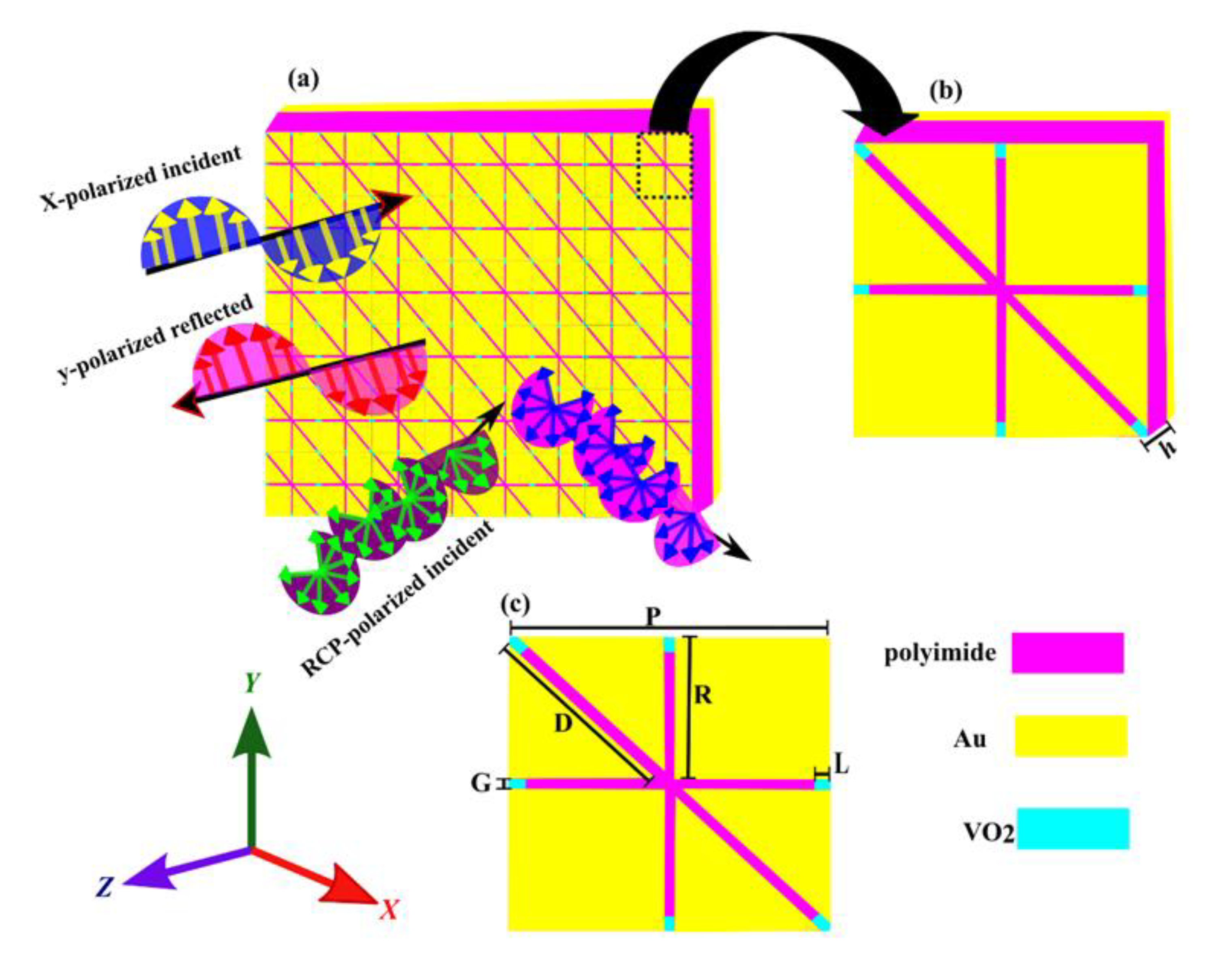
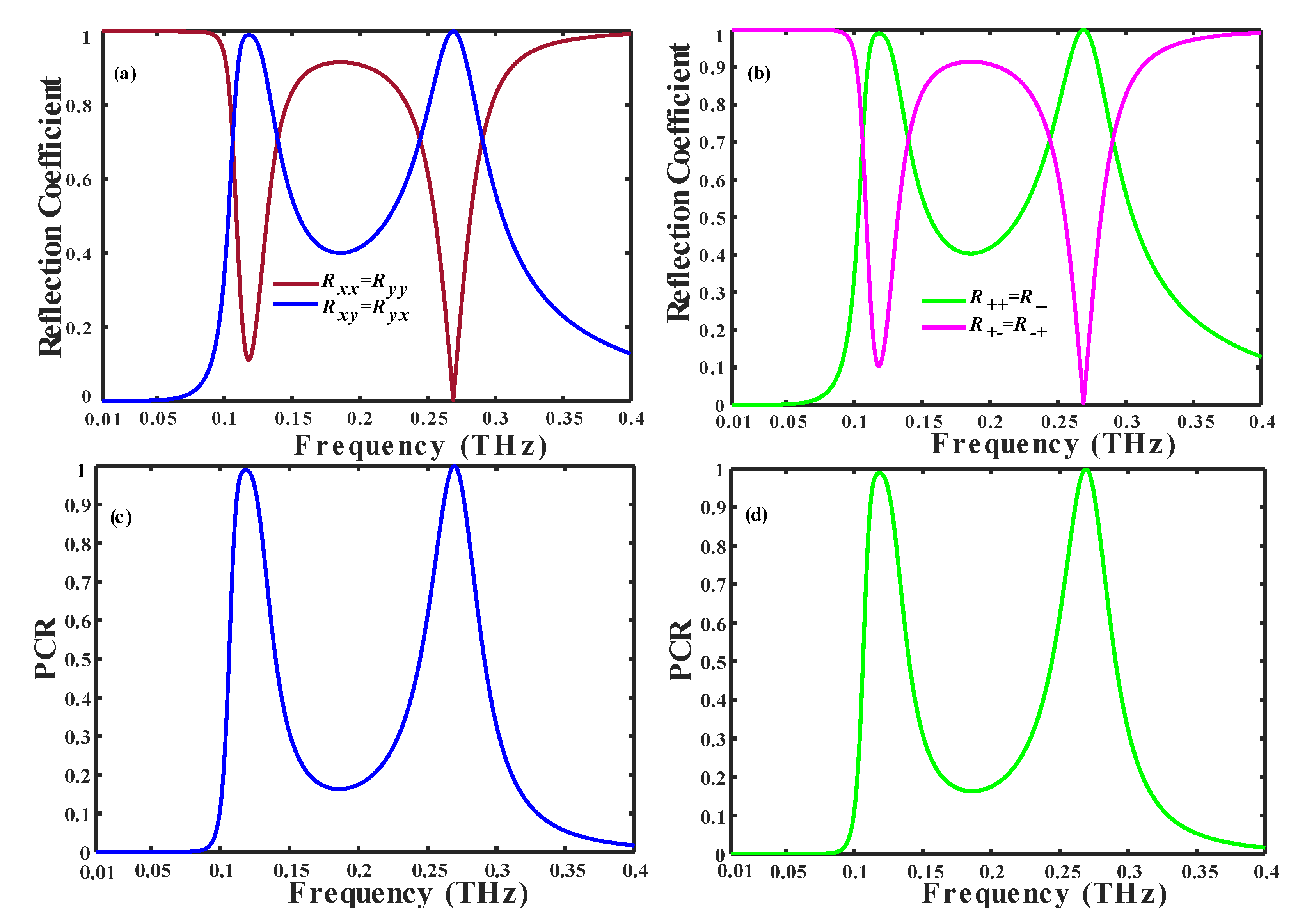
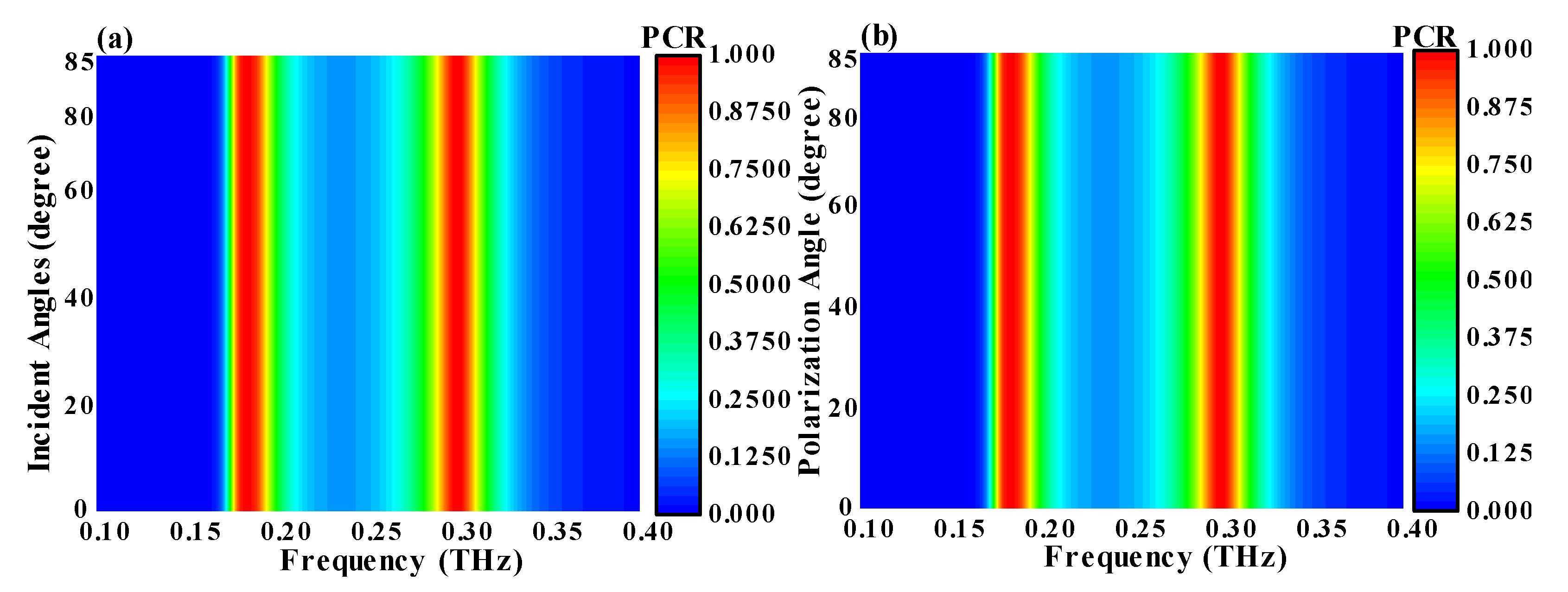


Disclaimer/Publisher’s Note: The statements, opinions and data contained in all publications are solely those of the individual author(s) and contributor(s) and not of MDPI and/or the editor(s). MDPI and/or the editor(s) disclaim responsibility for any injury to people or property resulting from any ideas, methods, instructions or products referred to in the content. |
© 2024 by the authors. Licensee MDPI, Basel, Switzerland. This article is an open access article distributed under the terms and conditions of the Creative Commons Attribution (CC BY) license (http://creativecommons.org/licenses/by/4.0/).


