1. Introduction
Plant root systems have the ability to reinforce the slope through both shallow root reinforcement and deep root anchoring [
1,
2,
3,
4], which effectively improves the stability of the slope [
5]. Currently, ecological engineering techniques mainly utilize herbaceous plants, shrubs, or a combination of herbaceous plants and engineering protection to effectively reduce the incidence of shallow landslides [
6,
7,
8,
9,
10,
11]. However, they are not effective for stabilizing deep landslides.Living stump slope stabilization is an innovative method for slope reinforcement that uses living tree stumps with strong regenerative capabilities [
12,
13,
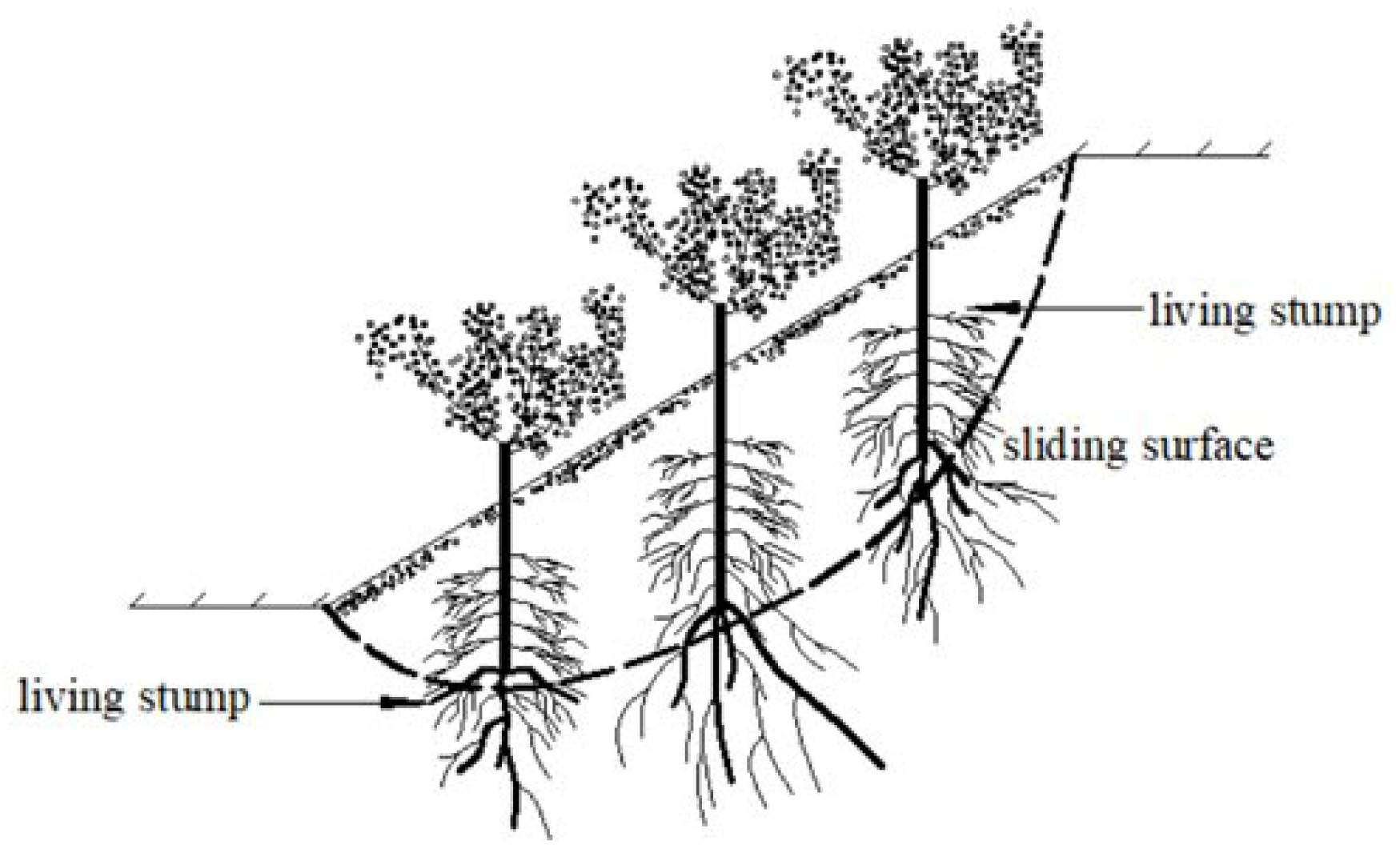
14]. In this approach, stumps are planted or inserted into the soil on a slope, allowing them to develop robust root systems over time, as illustrated in
Figure 1. The stumps act as natural anchors, binding the soil together and helping to prevent erosion and landslides.
Current research on how plant root systems reinforce slopes is mainly approached in two ways: (1) Treating the root system like a bar similar to soil nails and incorporating it into the soil for analysis, or (2) viewing the rooted soil as a root-soil complex and substituting the rooted soil layer with an equivalent reinforcement layer for analysis.
However, in research on the impact of plant root systems on slope stability, the common approach of treating roots as rod-like units or simplifying the root-soil complex as a homogeneous material neglects the three-dimensional spatial arrangement of plant root systems. This excessive simplification results in substantial limitations when it comes to understanding its true influence. The impact of three-dimensional plant root systems on slope stability is predominantly investigated through numerical simulations. Lionel Dupuy[
15] utilized finite element software to construct a three-dimensional virtual root structure and analyzed the mechanical response of the root/soil system under bending forces. Li[
16] investigated the root-soil composite using a 3D model that considers soils with varying cohesion. They explored how the spatial arrangement of root structures affects slope stability. Danjon[
17] used 3D in-situ digitization to gather precise root structure data of mature oak trees and analyzed their stability. The findings showed that uniform tree arrangement had minimal impact on soil stabilization, while a staggered arrangement of trees improved slope stability. Fan and Lai[
18] developed a simplified 3D root model, consisting of one taproot and four lateral roots, to assess the impact of vegetation layout on slope stability.Chia-Cheng Fan[
19] established a simplified three-dimensional root system model that comprehensively accounted for the three-dimensional geometric shape of the root structure and the characteristics of root elements. The model was employed to conduct a three-dimensional analysis of the stability of vegetated slopes. Ming[
20] utilized embedded beam elements to model tree roots and investigated how tree roots anchor under wind stress. Zhu[
12] and Jiang[
13], from the same research team, developed a 3D simplified model of living stump root systems that worked in conjunction with bamboo anchors to bolster slope stability. Their analysis revealed that living stumps with established root networks were effective at mitigating the risk of deep landslides.
Most studies on the reinforcement of slopes using plant root systems primarily rely on numerical methods to analyze 2D or 3D scenarios, with only a few researchers utilizing model experiments. Consequently, the understanding of the mechanical properties of living stumps remains limited. To address this gap, the current study employed 3D printing technology to create a three-dimensional model of a living stump root system for slope model experiments. This research was further enhanced by incorporating a 3D numerical model, which allowed for a deeper investigation into the reinforcement mechanisms of living stump slopes. These insights have significant real-world implications for better understanding the processes behind living stump slope stabilization and its application in slope reinforcement. These findings contribute to more sustainable and environmentally friendly approaches to slope stabilization. By utilizing living stumps, which are natural and renewable resources, these methods promote ecological balance and long-term stability of slopes. This research offers valuable guidance and reference for future studies in this field and aligns with the goals of sustainable development.
The use of living stumps for slope stabilization aligns with the principles of sustainable development by minimizing the environmental impact of engineering solutions and promoting the use of natural, renewable resources. Living stumps offer an ecological approach to slope reinforcement that leverages the natural growth processes of plants to enhance soil stability.Incorporating living stumps into slope stabilization strategies supports biodiversity by creating habitats for various plant and animal species. This method also aids in carbon sequestration, as the growth of plant roots captures carbon dioxide from the atmosphere and stores it in the soil.By prioritizing natural and sustainable methods of slope reinforcement, such as using living stumps, future engineering projects can reduce reliance on non-renewable resources and decrease the carbon footprint associated with traditional construction techniques. Moreover, these approaches contribute to long-term ecosystem health and resilience, ensuring that slopes remain stable and safe for both human and ecological communities.Future research in this field should continue to explore and refine the use of living stumps and other natural materials for slope stabilization. Such studies will play a crucial role in advancing sustainable development goals, supporting the health of ecosystems, and promoting environmentally responsible engineering practices.
2. Materials and Methods
2.1. Model Test Similarity Ratio
Due to the limitations of the test equipment and site conditions, the slope model test can only be carried out by reducing the prototype of the test object into a test model according to a certain proportion. The size, elastic modulus, and density of living stumps are selected as the basic dimensions according to Meymand's law. The geometric similarity ratio
is 15, the elastic modulus similarity ratio
is 1, and the density similarity ratio
is 1. The other similarity constants are calculated using the similarity theory[
21,
22] and the dimensional analysis method, as shown in
Table 1.
2.2. Model Test Design
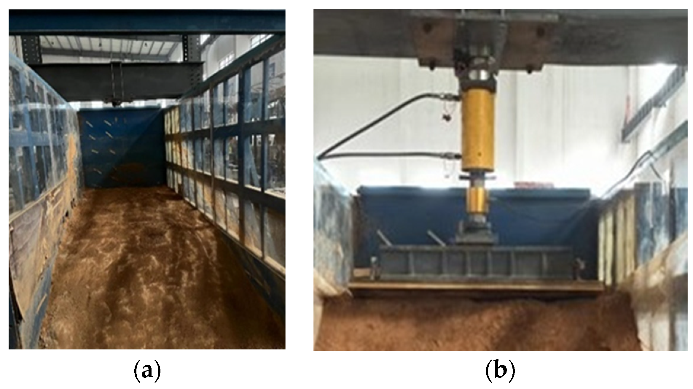
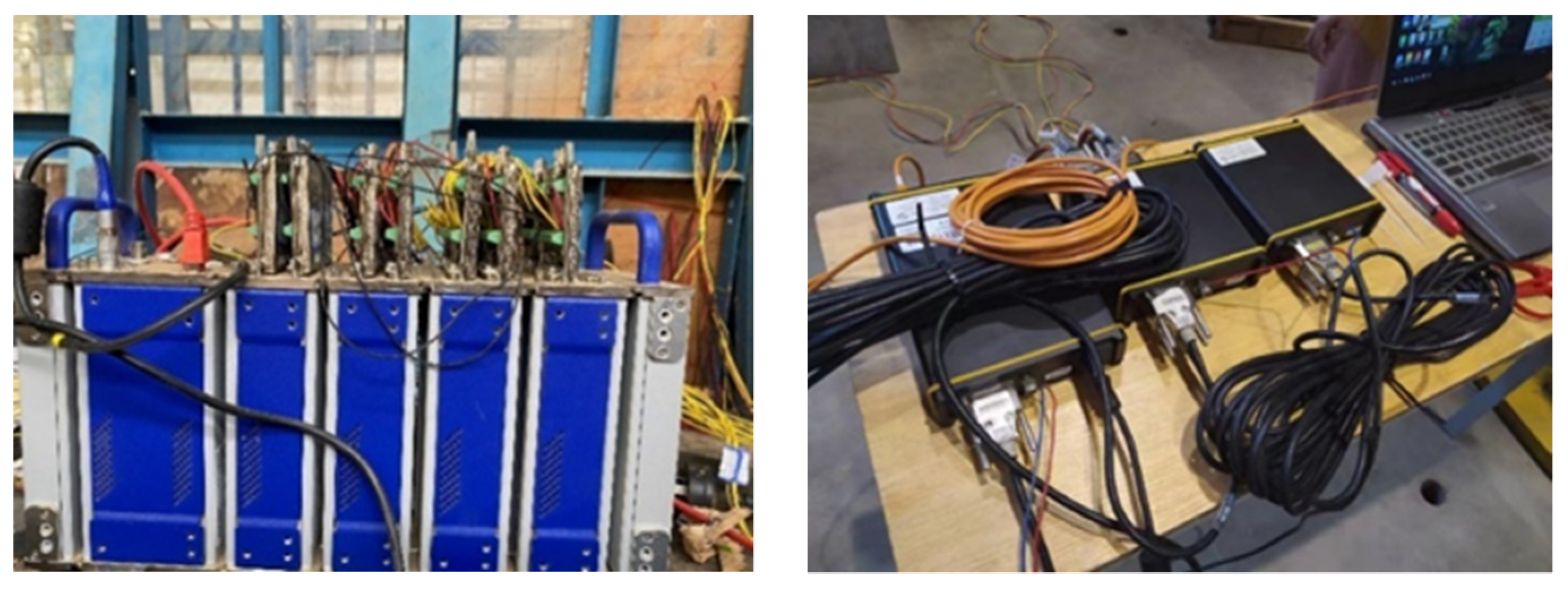
The model box used for the test has a length of 3 meters, a width of 1.5 meters, and a height of 2 meters and the loading device is an electro-hydraulic servo hydraulic jack with a maximum load of 500kN and a precision of 0.01kN. The test devices are shown in
Figure 2. The test soil is homogeneous clay, which was sampled in situ at the same location to ensure the consistency of its properties. The basic parameters of the soil were obtained in the laboratory, while the parameters of the living tree stumps were mainly obtained from literature[
23,
24]. The main parameters of the soil and the living tree stumps are presented in
Table 2.
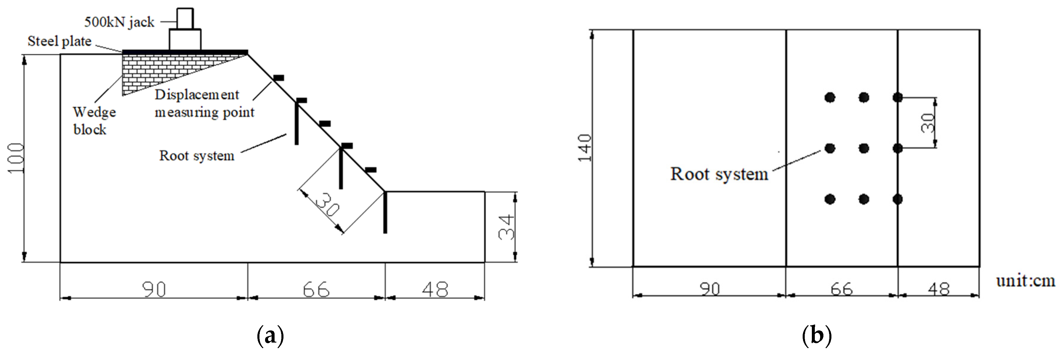
Nine living stumps were arranged in the slope model test, with three stumps in each row at the foot, middle and top of the slope, for a total of three rows. The distance between the living stumps was30cm, and the distance between each row of living stumps was also 30cm. According to the National Natural Science Foundation of China (3192), the slope model was selected.
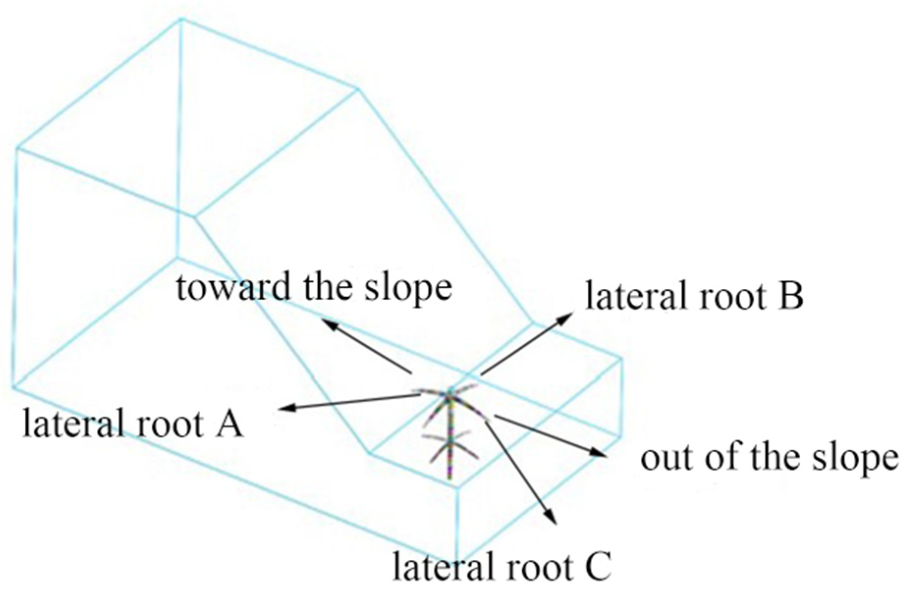
Figure 3 shows the slope model and the arrangement of living stumps. The root numbers of the living stumps at the foot of the slope are shown in
Figure 4, in which the lateral root A of the first layer is the lateral root growing vertically in the slope direction, and the lateral root B is the root growing vertically with the lateral root A. The lateral root C is the root that grows symmetrically with lateral root A and vertically outside the slope.
Five displacement meters are arranged on the slope surface to measure the horizontal displacement of the slope surface. Resistance strain gauges were used to measure the strain of each root system of the living stumps. The specifications of the strain gauges and displacement gauges are presented in
Table 3, and the data acquisition system used was Imc and Donghua data acquisition instrument, as shown in
Figure 5.
2.3. Selection and Modeling of Living Stump
The tap roots of the living stump should be sufficiently deep to penetrate the slope's sliding surface and reach the deeper soil layers, providing enhanced anti-shearing protection. The horizontal lateral roots should be extensive and long to offer strong horizontal anchoring. A root system that is deep-rooted, well-developed, and features long horizontal lateral roots can better stabilize the slope [
25]. To optimize the slope reinforcement effect of the living stump support structure, an elm tree with a robust root system was selected for the study. Elm trees have a VH root system type [
24], characterized by abundant horizontal roots and long taproots that extend deeply into the soil.
For the purpose of analysis and discussion, the following assumptions are made: (1) It is presumed that the root system of living elm tree stumps will develop as anticipated after planting in the soil, with a vertical, deep taproot and robust lateral roots. (2) The root system model excludes roots with smaller diameters, such as fibrous roots and heart roots, as these have a limited anchoring effect on the soil[
26]. (3) All roots are assumed to experience forces and deformation within the elastic range, neglecting any plastic deformation and assuming that the root system's elastic modulus remains stable. (4) All root sections are assumed to be circular, and root section size is assumed to be positively correlated with root length. Based on these assumptions and elm growth law [
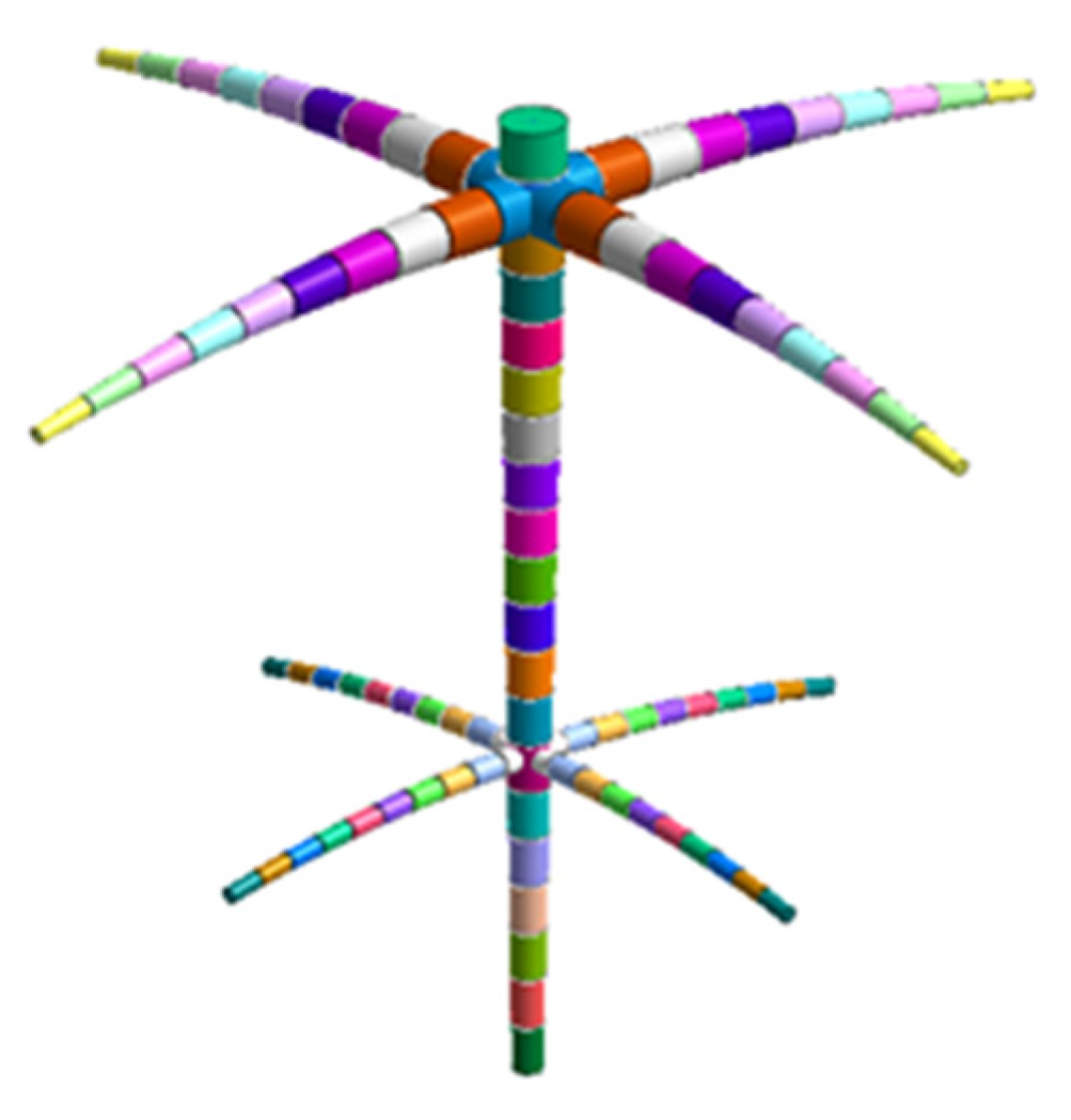
27], a simplified model of an elm living stump was created. The tap root was 3m long, with the first layer lateral root and the second layer lateral root divided 0.25m and 1.5m from the top of the tap root respectively. The angle between each lateral root was 90° and the angle between the lateral root and the horizontal direction was approximately 20°.
Table 4 displays the root size parameters and
Figure 6 (a) illustrates the living stump model created by 3Dmax.
Mickovski [
28] conducted research on the reinforcement of soil using plant root analogs with simple geometric shapes, but the materials used to simulate the root system were rubber or wood (or both), respectively as low stiffness and high stiffness materials. These materials help to simulate the flexible and rigid characteristics of the root system, but their performance is not ideal. Furthermore, since these analogs are essentially straight rods, the branching pattern is simplified, thus the geometric models made with these materials are subject to greater limitations. Liang [
23] found that the elastic modulus of Acrylonitrile-Butadiene-Styrene (ABS) material is 650Mpa, and the tensile strength is approximately 17Mpa, which is similar to the real elm root system and is suitable for simulating various common sizes of roots. Therefore, ABS material is chosen for printing, and 3D printing technology can be used to print models of any shape, as shown in
Figure 6 (b).
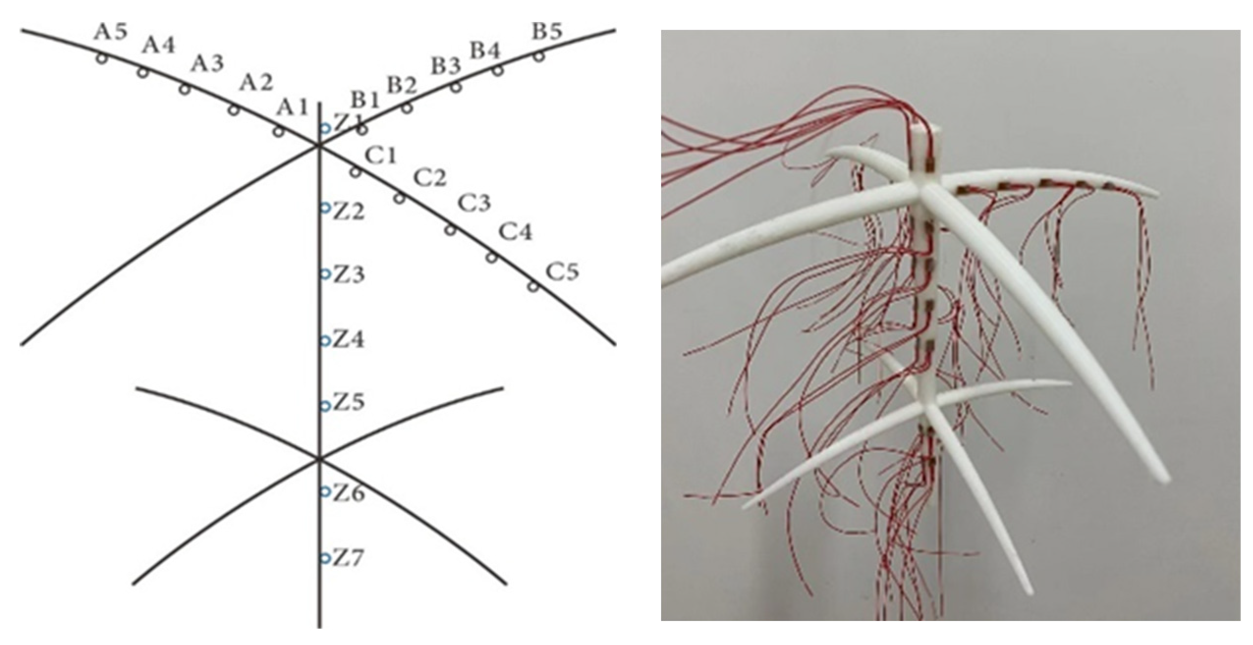
In order to determine the strain variation law of living stumps, strain measurements were conducted on the roots at the foot, middle, and top of the slope. Seven strain measuring points (Z1, Z2, Z3, Z4, Z5, Z6 and Z7) were placed at 1.5, 4, 6.5, 9, 11.5, 14 and 16.5cm from the top of the tap root, respectively, to measure the tensile and compressive strains and bending strains of the tap roots. Additionally, five strain measuring points (A1,A2,A3,A4,A5) were placed at 2,4,6,8,10cm from the branch point to measure the tensile and compressive strains of the lateral roots.
Figure 7 illustrates the arrangement of the strain gauges on the living stump.
Vertical loading was conducted using a 500kN class jack, with each load being 5kN. After a 30 second pause, data was recorded and the next load was applied. The loading was stopped when the slope experienced significant sliding.
Table 5 displays the test loading regime.
3. Results
3.1. Roots Stress Characteristics
Due to the fragility of the strain gauge, some data was not collected. It was assumed that the living stumps were in an elastic state during the experiment (the plastic deformation was not considered). The axial stress of the root was calculated using the formula: . Where is the axial tensile and compressive stress of the root system, is the elastic modulus of the root system, is the collected tensile and compressive strain. Due to limitations in the strain gauge channels, strain data was only collected for the living stump in the middle of the slope.
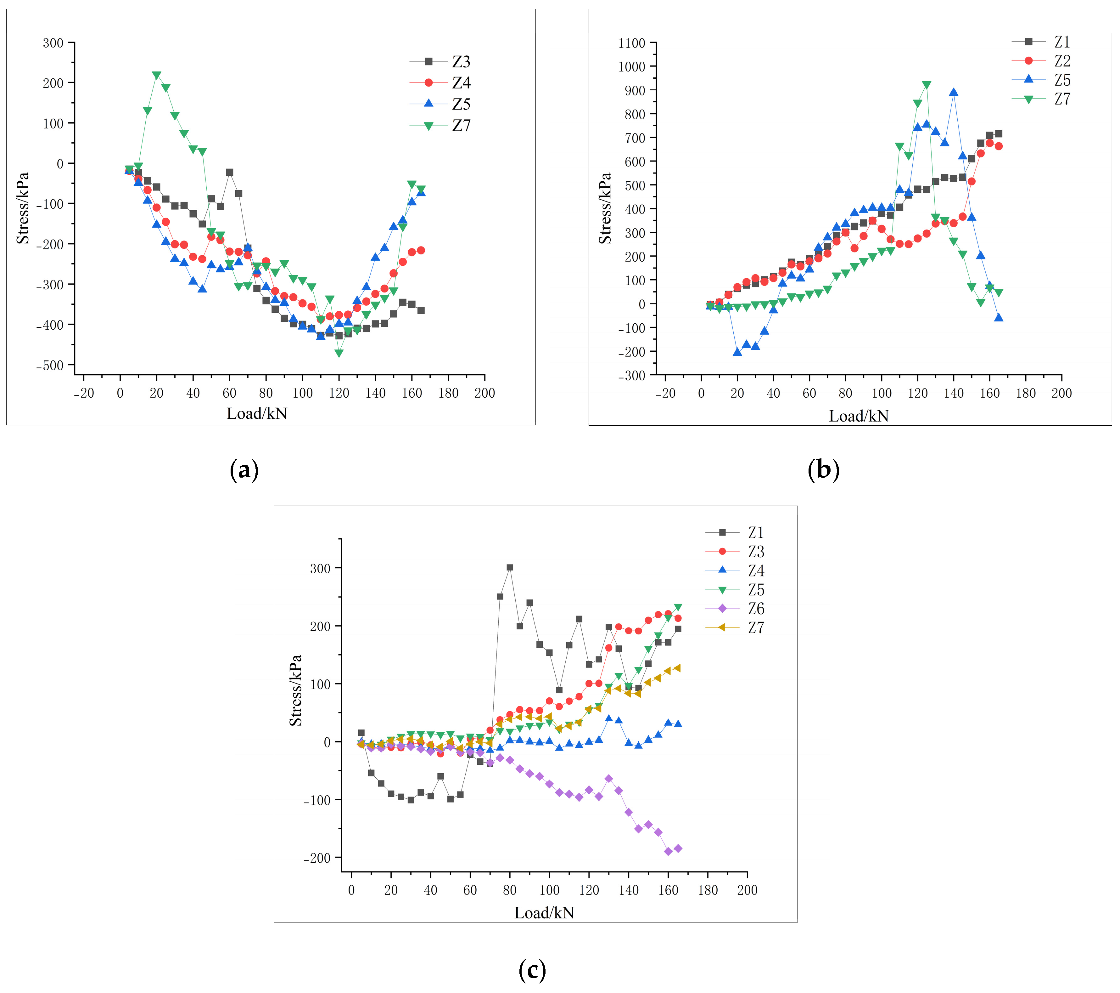
It can be seen from
Figure 8 (a) that the tap root of the living stump at the top of the slope was mainly subjected to compressive stress, and the compressive stress increased as the load increased. The compressive stress of measuring points 3, 4, 5 and 7 reached its peak at 120kN, and then gradually decreased, which may be because the soil at the top of the slope had been damaged, and the increased load did not act on the root system. All the measuring points on the tap root of the living stump in the middle of the slope were subjected to tensile stress, and the tensile stress of measuring points 1 and 2 increased as the load increased. Except for measurement point 6, the other measuring points of the tap root of the living stump at the slope foot were mostly under tensile stress. Measuring points 3, 5 and 7 were all subjected to small tensile stress at 0-110kN, and then the tensile stress increased rapidly with the increase of load. This may be because the soil at the slope had already started to slide, and the tap root system was exerting its tensile strength to prevent the soil from sliding further.
Under static load conditions, it is evident that the tap root of the living stump at the top of the slope was under compressive stress, while the tap root of the living stump in the middle and foot of the slope was under tensile stress. Therefore, the tap root in the middle and foot of the slope mainly exerted their tensile strength to increase the stability of the slope, while the tap root at the top of the slope did not contribute to the stability of the slope.
According to the formula
the bending moment of the tap root is calculated. Where
is the bending moment of the root system,
is the section modulus, and
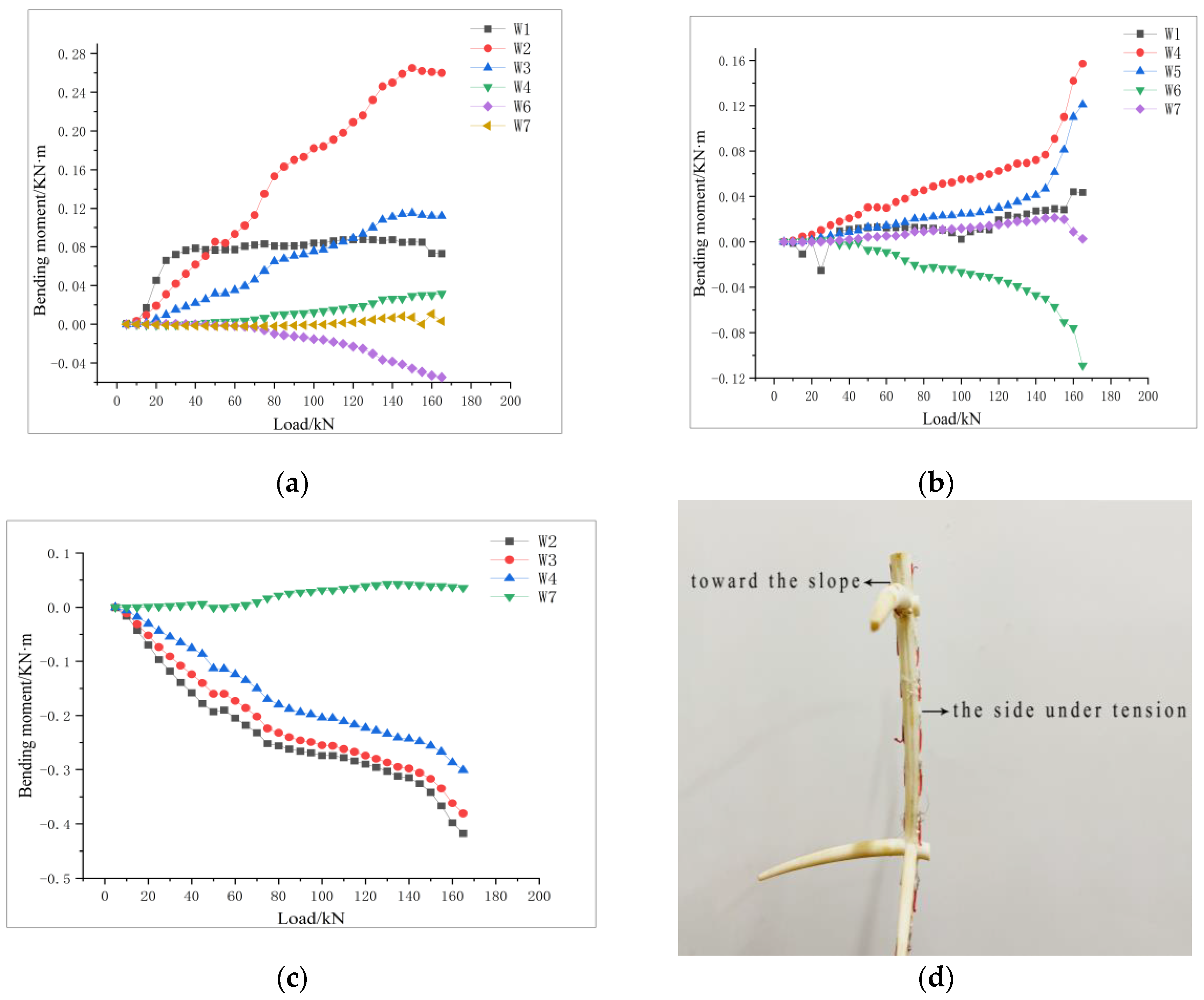
is the diameter of the root system at the measuring point. When the front portion of the taproot (facing the slope) experiences tension, the bending moment becomes positive. It can be seen from
Figure 9 that the points 1, 2, 3 and 4 of the tap root at the foot of the slope were subjected to an positive bending increasing moment, while the root front was subjected to tension. The measuring point 2 under the first layer lateral root experienced the fastest and largest bending moment. The positive bending moment of point 4 and 5 of the tap root in the middle of the slope was gradually increasing, but the value was small. The bending moment of measuring point 7 was almost 0, while the bending moment of point 6 was subjected to a gradually increasing negative bending moment. From
Figure 9 (c), it is clear that the bending moment of point 7 of the tap root at the foot of the slope was almost 0, similar to the point 7 of the tap root in the top and middle of the slope. The bending moments of measuring points 2, 3 and 4 increased with the increase of load, and all of them were subjected to negative bending moments, which were tensile behind the root, with the negative bending moment value of measuring point 2 being the largest.
Figure 9(d) shows the deformation diagram of the living stump at the top of the slope excavated after the test. It is evident that the tap root of the living stump at the top of the slope was mainly subjected to negative bending moment, causing the root to be pulled behind. Meanwhile, the tap root of the living stump at the middle and foot of the slope was mainly subjected to positive bending moment, resulting in the root being pulled in front. The 2nd measuring point of the living stump, which is located under the first layer of lateral root, was the main part of the root bending, while the end of the tap root was almost not bending. Additionally, the tap root of the living stump at the foot of the slope was subjected to the largest positive bending moment, indicating that the tap root at the slope foot had a certain anti-sliding effect on the slope soil, similar to an anti-slide pile.
3.2. Lateral Roots Stress Characteristics
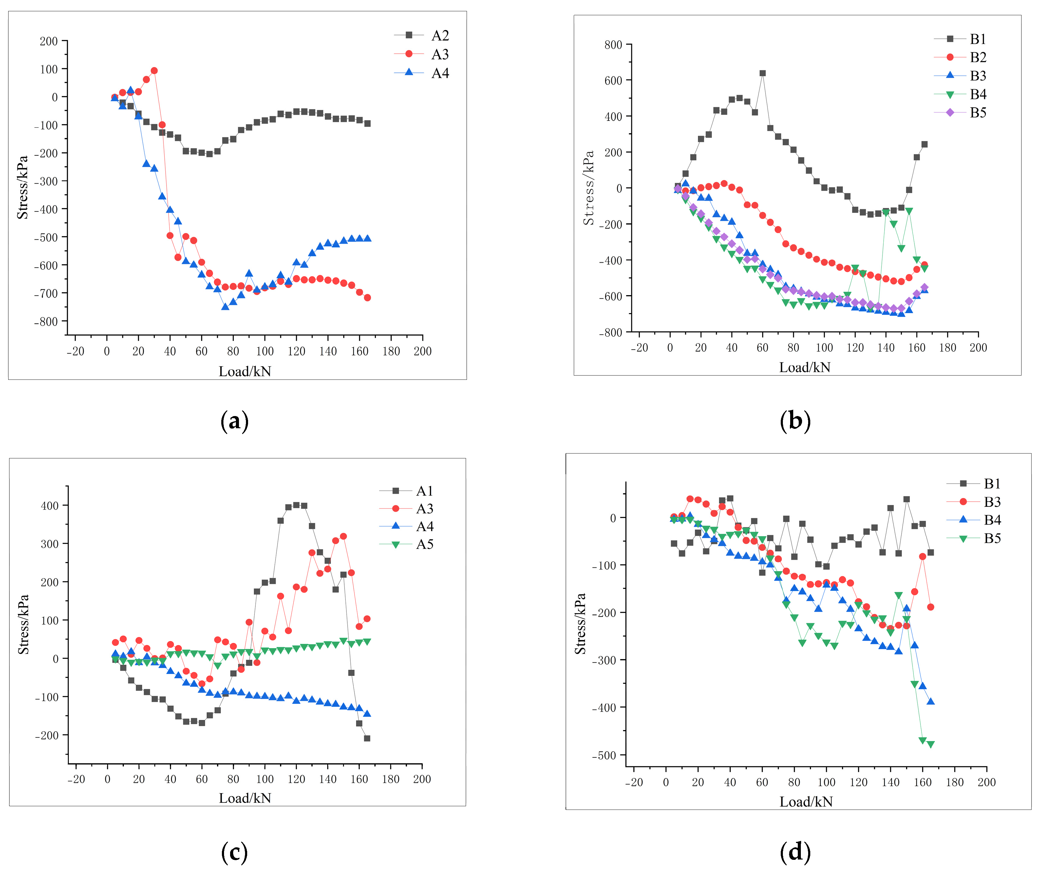
Figure 10 shows the axial tensile stress of the lateral root system of the living stump at the top and middle of the slope. The measuring points 2, 3 and 4 of the lateral root A of living stump at the top of the slope are all under compressive stress, with the compressive stress at measuring point 2 being comparatively small and the change in stress being slow and gradual. The compressive stress of measuring points 3 and 4 increases rapidly after the load reaches 30kN, with the stress increasing further with the increase of load. The lateral root B at the top of the slope experienced a tensile stress at point 1 that increased initially before decreasing, while the compressive stress at points 2, 3, 4 and 5 increased gradually as the load was increased. The lateral root A at the middle of the slope experienced a compressive stress at points 1 and 3 that changed to tension as the load increased, while point 4 experienced a gradually increasing compressive stress. The tensile stress at point 5 was small and increased slowly. For the lateral root B at the middle of the slope, all four measuring points experienced a gradually increasing compressive stress, with the maximum compressive stress of points 4 and 5 being reached at the last load.
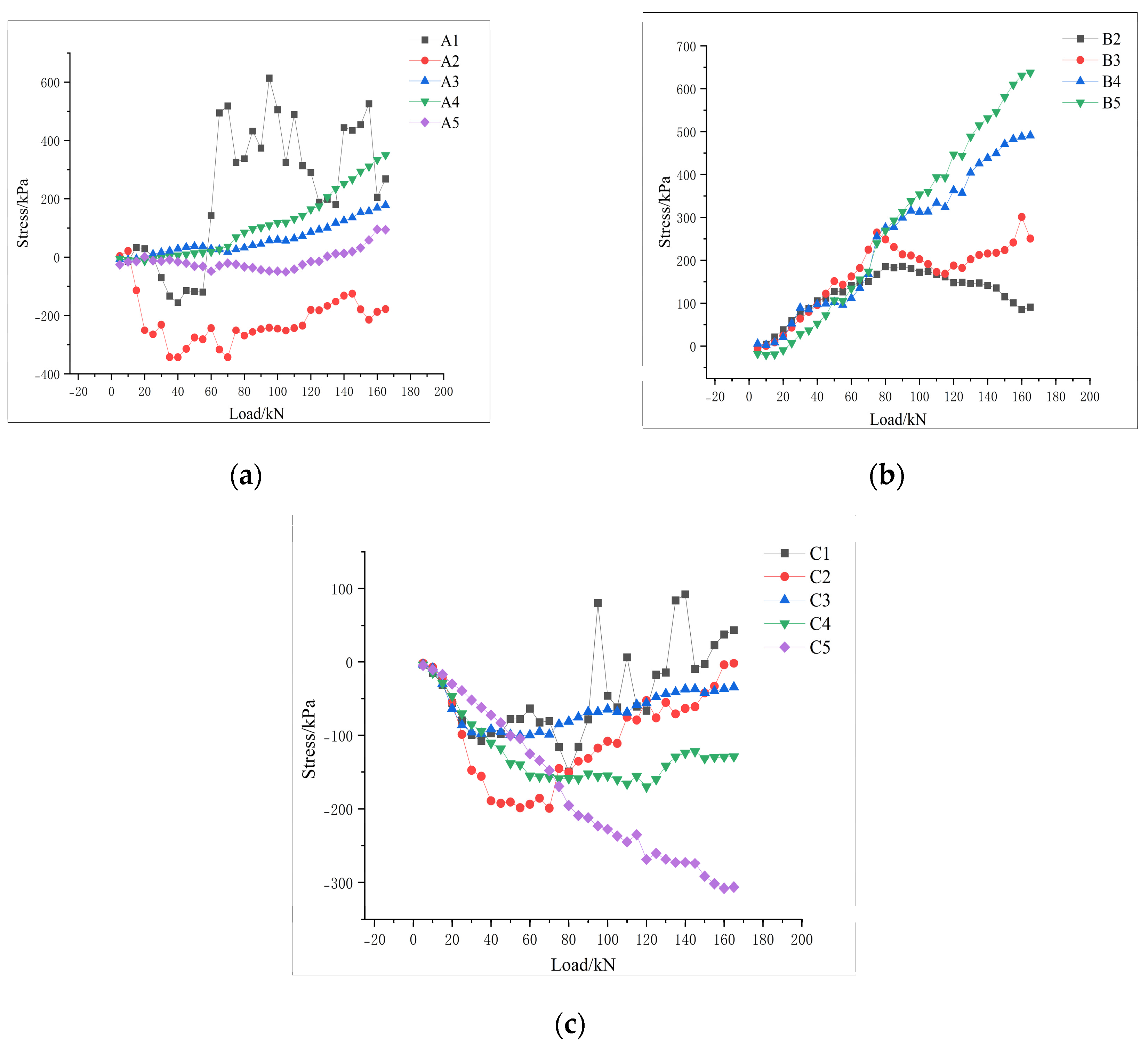
The axial stress of lateral root system of living stump at slope foot is shown in
Figure 11. For the lateral root A, point 1 experienced compression before transitioning to tension, with a large tensile stress value. Points 3 and 4 experienced gradually increasing tensile stress. The measuring points 2, 3, 4 and 5 on the lateral root of the living stump B at the slope foot were all subjected to tensile stress, with the tensile stress at points 4 and 5 gradually increasing with the increase of the load and reaching its maximum value. For the lateral root C, measuring point 1 experienced an initially increasing compressive stress before alternating between tension and compression, which suggests that the strain gauge may have been damaged. Measuring points 2 and 3 are subjected to compressive stress which gradually increases and then decreases. The compressive stress at measuring point 4 gradually increased from 0-80kN before becoming stable. The compressive stress at measuring point 5 increased with the increase of load before reaching its maximum value.
Based on the analysis of
Figure 8,
Figure 10, and
Figure 11, it can be concluded that under static load conditions, the lateral root systems growing in the middle and lower parts of the slope, as well as the B lateral roots growing laterally at the foot of the slope, mainly exert their tensile strength to increase the stability of the slope, while the lateral roots at the top of the slope hardly contribute to the tensile strength.
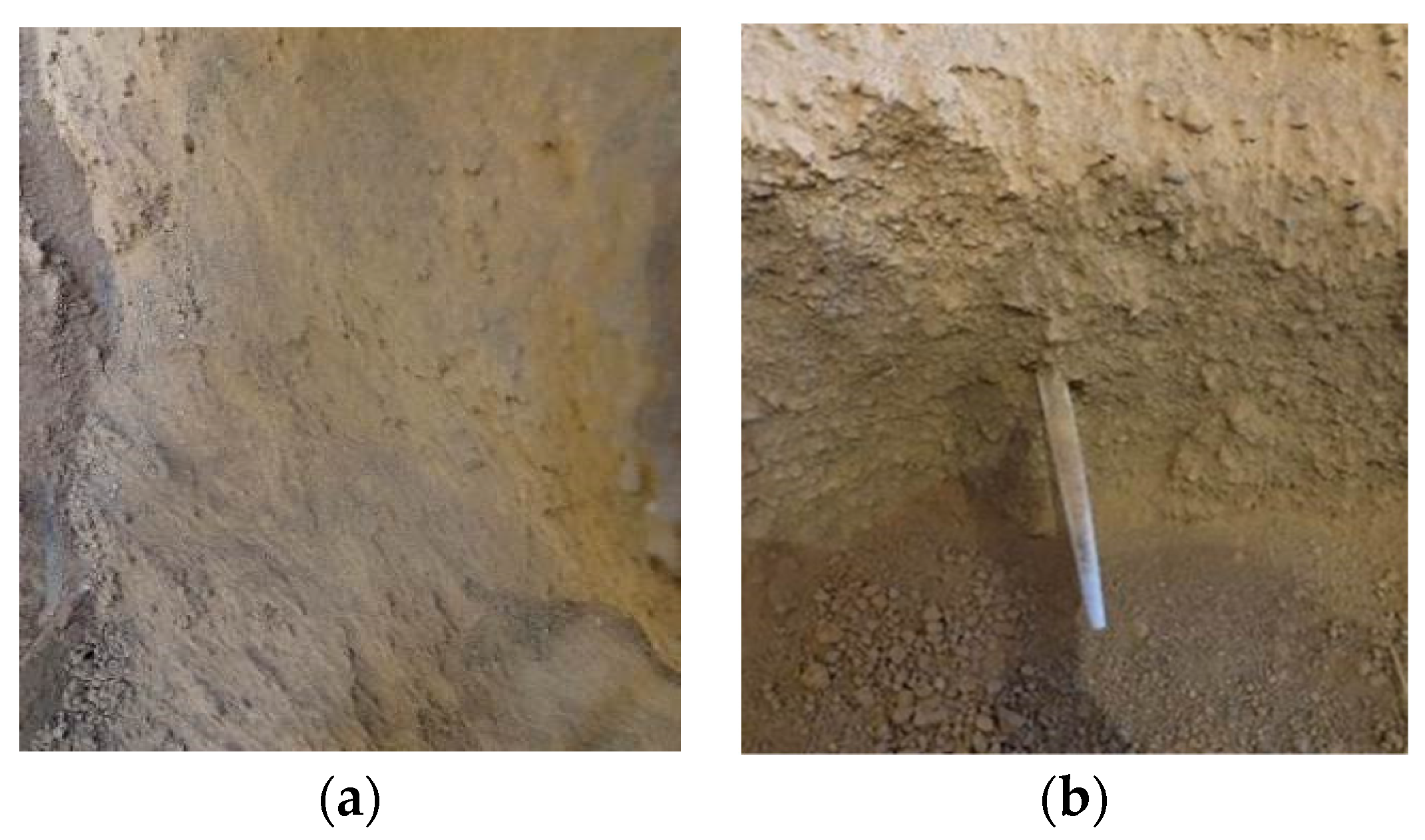
Figure 12 shows the living stump slope soil after excavation. It is evident that the soil is looser in the absence of roots but denser where there are roots. This can be attributed to the presence of living stump which acts as an anti-slide pile, preventing soil slide, anchoring the soil particles, thus increasing the soil stress in the presence of the living stump.
3.3. Slope Surface Displacement
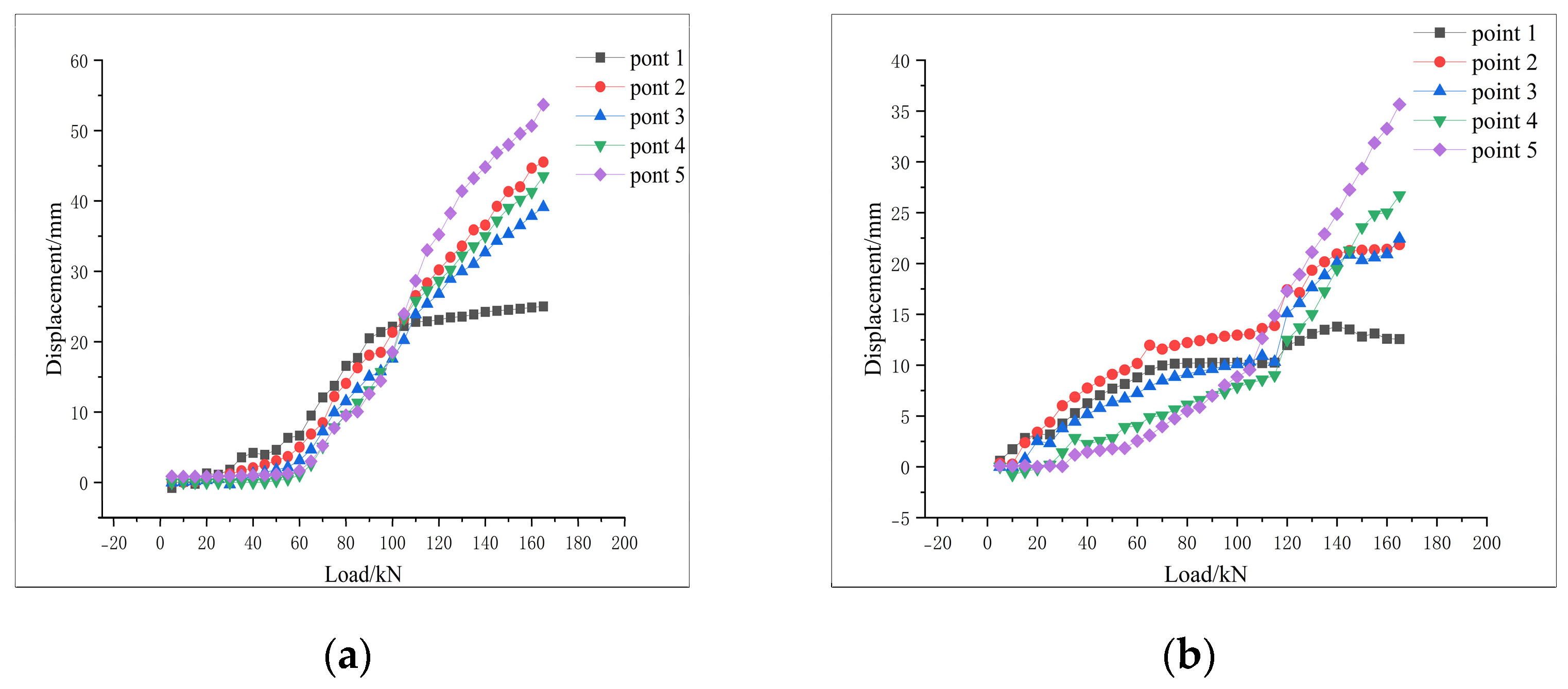
Comparing the displacement of the prototype slope with that of the living stump, it can be observed form
Figure 13 that the displacement variation trend of both slopes is similar, and the displacement of each measuring point of the living stump is significantly lower than that of the original slope. At the start of the loading process, the load was not effectively transferred to the foot of the slope, resulting in the displacement of measurement point 1 and 2 increasing drastically with a high value, while the displacement of measurement point 3,4 and 5 increased gradually with a small value. In the later stages of loading, the displacement at the slope top gradually stabilized, whereas the displacement at the slope foot increased rapidly due to the slope sliding.
4. Discussion
4.1. Model Reliability Verification
The prototype slope was numerically simulated using Midas GTS/NX, which allowed for a more comprehensive analysis of the reinforcement mechanism of living stump slope. Because of the complexity of using 3-D solid elements to grid the root structure, embedded beam elements were used to simulate the root structure of living stumps in MIDAS GTS/NX [
29]. The embedded element method assumes that all root element nodes are within the host soil. The translational kinematic degrees of freedom (d.o.f.) of embedded root nodes are computed based on interpolation values from nearby soil nodes, which are located by a specific algorithm. The region where the root system is situated consists of two materials: roots and soil. During analysis runs, the mass and stiffness of embedded roots are incorporated into the model. The method does not account for stress transmission across the interface and makes assumptions regarding the translational movement of embedded root elements. This approach offers a streamlined representation of the root structure while still capturing its impact on soil mechanics.[
30]. Furthermore, it allows for a more efficient and accurate simulation of the soil-root interaction compared to using solid elements to represent the complex geometry of the root system.Root slippage, arising from significant deformations in the root-soil system, may not occur adequately due to the constraints of embedded beam elements. To achieve more precise simulations of root-soil interactions, it is essential to stay informed about the latest developments in this area and consider integrating friction laws that govern root-soil interaction [
29,
31,
32,
33,
34]. This approach allows for a more accurate representation of the complex interactions between roots and soil, leading to enhanced simulation results. However, it is important to validate the results of the simulation against model tests to ensure the accuracy and reliability of the method. The tap root and lateral root of the living stump model were divided into 20 units respectively.
Figure 14 shows the living stump model established by MIDAS GTS/NX and
Table 6 shows the root size parameters.
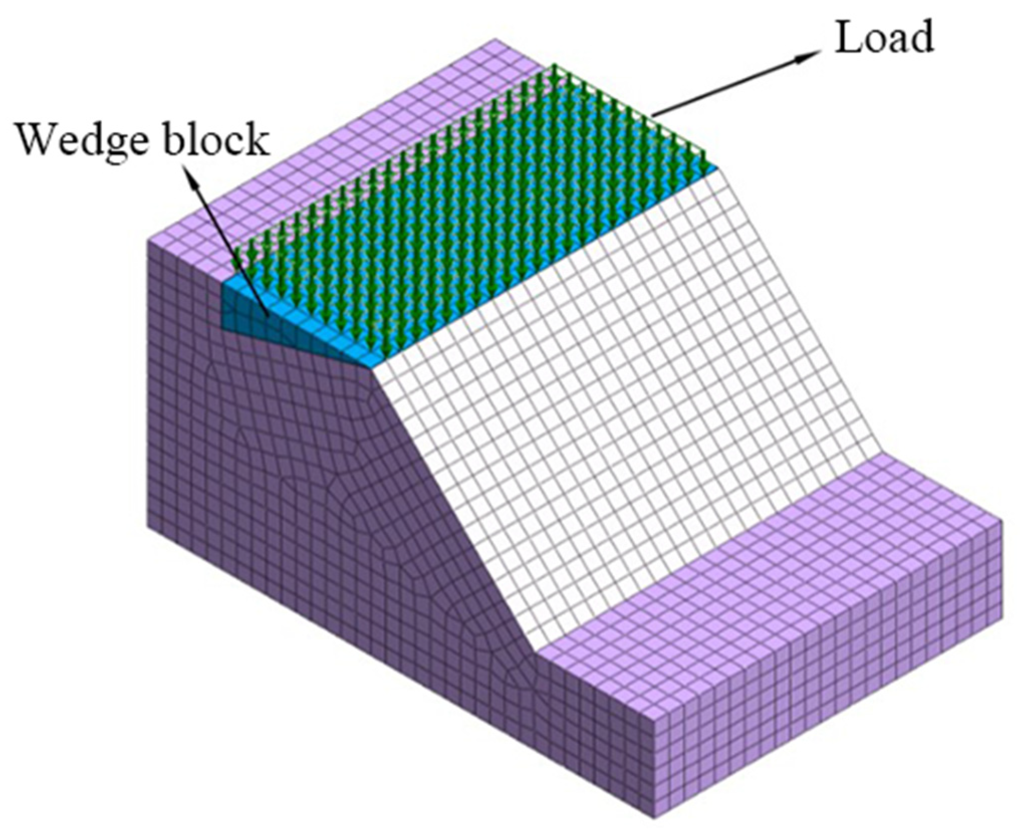
According to the geometric similarity ratio of 1:15 in the model test, the prototype slope model was established by Midas GTS/NX. Mohr-coulomb constitutive model was used for soil and mesh was generated by hybrid hexahedral mesh generator. The lateral displacements in the four directions and the displacements at the bottom of the model are fixed. Nine living stumps are arranged in three rows of 3 each, with a horizontal spacing of 4.5m and a vertical spacing of 4.5m.
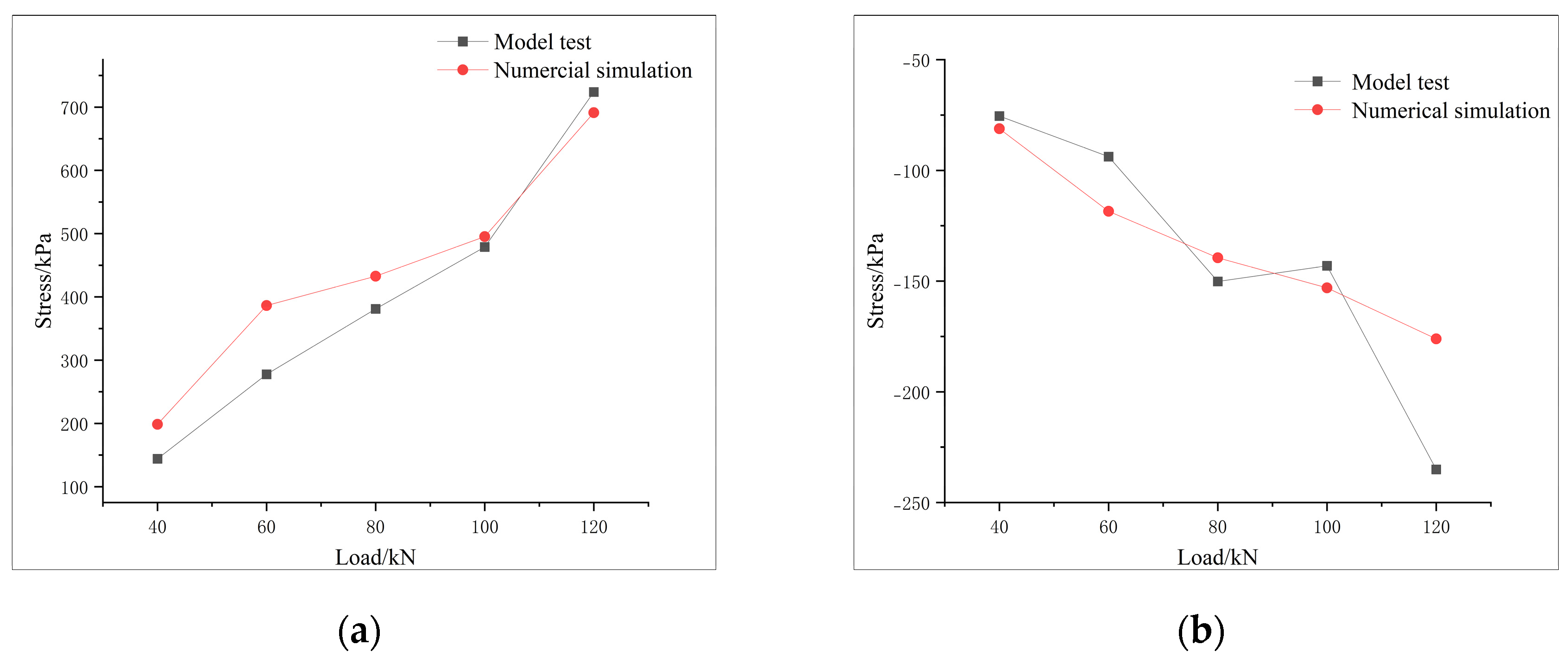
Figure 15 shows the slope model established by Midas GTS/NX. Loads of 40KN, 60KN, 800KN, 100KN and 120KN were applied to the top of the slope model, respectively. As can be seen from
Figure 16, both the model test and the numerical model showed similar trends in the root stress and the magnitude of stress increased with increasing load. The small error between the model test results and the numerical model indicates that the numerical model effectively predicted the slope's behavior under various loading conditions.
4.2. The Shear Stress of Living Stump Slope and Original Slope
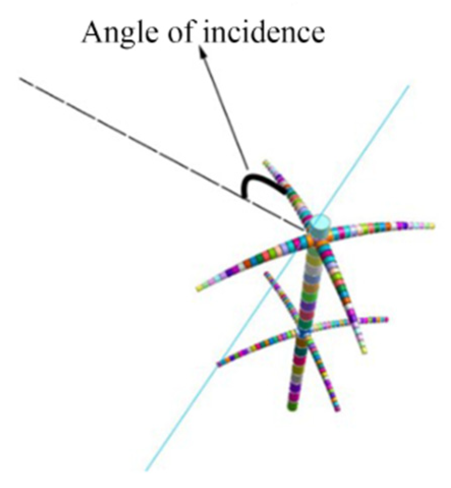
When rotating lateral roots, the first and second layers lateral roots are rotated with the tap root as the axis of rotation. The incident angle of the lateral root is defined as the angle between the lateral root and the normal line of the strike line of the slope foot, as shown in
Figure 17.
In a slope model test, a vertical load is applied to simulate the weight of the soil and any additional external loads that may be present in the actual slope. However, in the natural environment, the slope is primarily affected by the force of gravity acting on the soil and rock mass. Therefore, the dead weight field is applied to the slope and the stress analysis is carried out by establishing the prototype slope model with or without living stump.
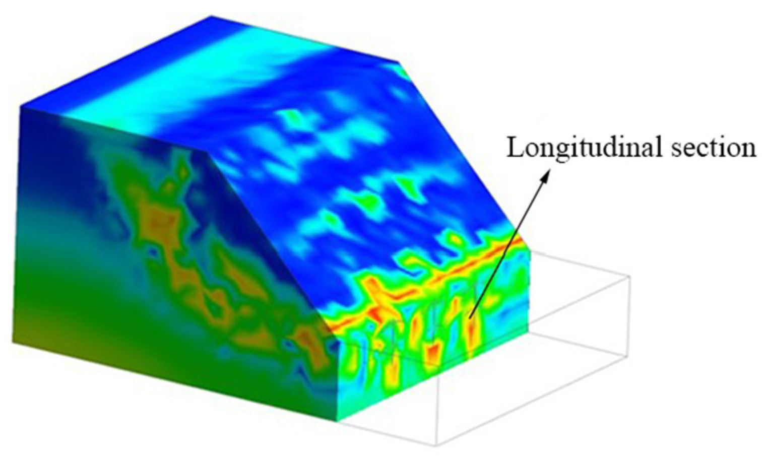
Figure 18 shows the longitudinal profile of the slope.
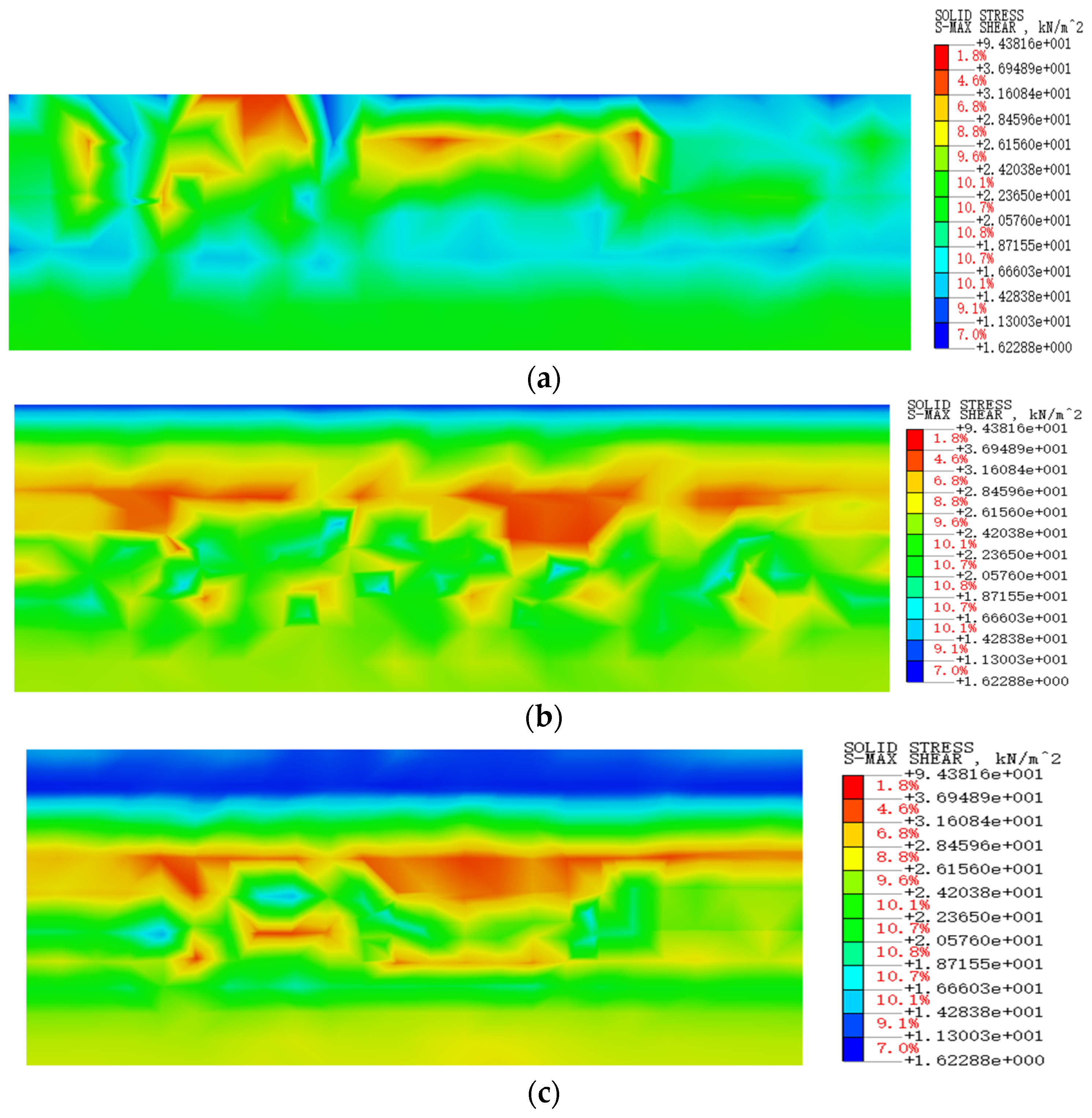
Figure 19 and
Figure 20 shows the soil shear stress at longitudinal section of the unsupported slope and the living stump slope (the incident angle of the lateral roots is 0°).
It is evident that the maximum shear stress of the soil at the foot, middle and top of the unsupported slope is mostly concentrated in the shallow soil layer, forming a connected zone. However, due to the exist of living stumps, the maximum shear stress of soil at the foot, middle and top of the slope moves to the deeper soil layer. This cause the shear stress in the root area to become larger, while the shear stress on both sides of the soil becomes smaller and no connected area is formed. This is because, when the soil on the slope slides, there is a relative dislocation between the root and soil, causing the root to deform and generate tensile stress. The interaction between the roots and soil [
24,
33] gradually transfers shear stress in the soil to the living stump.The presence of living stumps at the slope foot has the best effect on causing the shear stress area of the soil to move towards a deeper soil layer. This is because the living stumps tap roots at the slope foot across the potential sliding surface. Due to the tap root's vertical growth, it has a certain rigidity and strong tensile resistance. The findings align with the conclusions in [
18]. Through the interaction of the root and soil, the taproot transmits the thrust of slope sliding to a deeper and more stable soil layer. The slope sliding is prevented due to the anchorage and passive resistance of the stable stratum to the vertical taproot, resulting in improved slope stability. Through the excavation of the test slope, it was discovered that the soil at the position of the living stumps is compact and that the soil particles are better bound by the roots. Additionally, the soil stress is more concentrated in this area. In contrast, the soil at the position without living stumps is loose, as shown in
Figure 12. These findings are consistent with the numerical simulation, which further suggests that the presence of living stumps has the same effect as anti-slide piles in preventing soil slope from sliding.
4.3. The Influence of Lateral Roots on the Slope Reinforcement Mechanism
In order to explore the influence of the lateral root system of living stumps on the reinforcement mechanism, the Strength reduction FEM method is used to analyze the stability of the slope with or without lateral roots. The slope stability without lateral root system is 1.302, which is 9.4% lower than that with lateral roots.
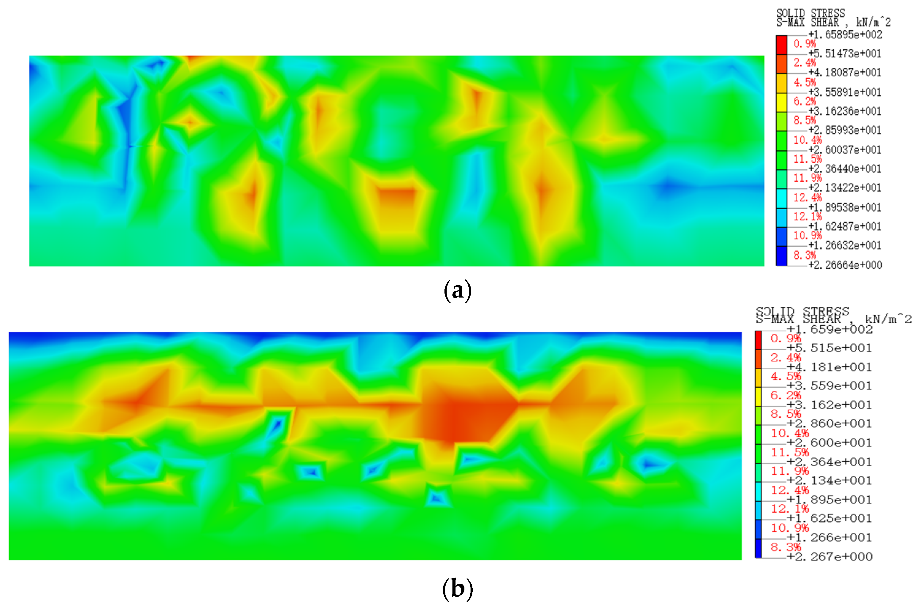
Figure 21 shows the soil shear stress of transverse section in the middle of slope with or without lateral root system. By comparing the Figures (a) and (b), it can be seen that the lateral root system has minimal impact on the shear stress of soil at the middle and top of the slope, but has a significant influence on the shear stress of soil at the slope foot. In the absence of a lateral root system, the shear stress of soil near the slope foot is concentrated in the shallow soil layer. However, when a lateral root system is present, the shear stress of soil at the slope foot shifts to the deeper soil layer. This is because the lateral root system has a significant impact on the shear stress distribution in the slope due to its growth pattern in all directions, including the deep direction [
35,
36]. This growth pattern creates a mesh-like structure that binds the soil particles more effectively[
37]. Additionally, the vertical root system has higher stiffness and tensile strength, and grows vertically along the depth direction, serving as the skeleton of the entire mesh structure. The combined effect of the tap root and lateral root system forms a solid overall structure that can withstand the soil shear stress. This reinforcement mechanism causes the region of maximum shear stress to shift to the deeper soil layer, which ultimately increases the slope stability.
Figure 22 shows the soil shear stress of transverse section in the middle of slope when the incident Angle of lateral root is 0° and the incident Angle is 40°.When the incident Angle of lateral root is 40°, the shear stress area of soil in the middle and lower part of the slope is shallow, and the shear stress area of soil in the lateral root A of living stump at the slope foot is concentrated. When the lateral root has an incident angle of 0°, the shear stress area of the soil is deeper in the middle and lower parts of the slope surface. In contrast, the shear stress area of the soil around the lateral root A of the living stump at the slope foot is well separated. The reason for this phenomenon is that when the slope soil slides, the incident angle becomes 0°, and the sliding force of the soil applies to the lateral root A. As a result, the lateral root and the soil are relatively staggered. The root generates tensile stress due to deformation, causing the shear stress area of the soil to gradually transfer to the root, which enhances the slope stability. However, when the incident angle is 40°, only a portion of the sliding force acts on the lateral root A. In this case, the lateral root A cannot fully exert its tensile strength, and the shear stress area of the soil around the root is not significantly improved. As a result, the slope stability is not as enhanced as when the incident angle is 0°.
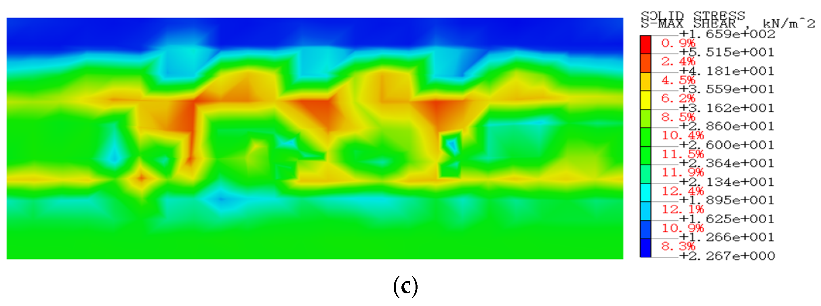
In
Figure 23, it can be observed that the area of maximum shear stress when the incident angle of the lateral root is 0° is deeper compared to when it is 40°. As mentioned earlier, when the incident angle is 0°, the lateral and tap root system forms a solid space and overall structure that efficiently undertakes the soil shear stress. However, when the incident angle is 40°, the lateral root and tap root system do not form a solid space and overall structure, resulting in the maximum shear stress being shallower. Therefore, the stability of the slope is not improved as much as when the incident angle is 0°.
5. Conclusions
(1) Under static load, the displacement of the living stump slope is similar to that of the original slope, whereas the displacement of the former is significantly smaller than that of the latter. The tap root, as well as the lateral root A growing in the slope direction and the lateral root B growing laterally of the living stump in the middle and lower sections of the slope, effectively exert their tensile strength to enhance the stability of the slope.
(2) The tap roots of the living stump in the middle and lower of the slope are mainly subject to positive bending moment and the front part of the roots are tensioned, while the tap root at the top of slope is mainly subject to negative bending moment. Measuring point 2 (under the first layer lateral root) is the main bending part of the tap root.
(3) The living stumps tap roots at the slope foot across the potential sliding surface, due to the tap root vertical growth and has certain rigidity and strong tensile resistance, through the interaction of root and soil, the shear stress of the soil gradually transfers to the root system of the living stump, which makes the shear stress area of the slope soil deeper and improves the stability of the slope.
(4) The lateral root growth pattern creates a mesh-like structure that binds the soil particles more effectively. the vertical root system has higher stiffness and tensile strength, and grows vertically along the depth direction, serving as the skeleton of the entire mesh structure. The combined effect of the tap root and lateral root system forms a solid overall structure that can withstand the soil shear stress, which ultimately increases the slope stability.
Author Contributions
All authors contributed to this study’s conception and design. Investigation, writing—original draft preparation, and writing—review and editing, W.L.; supervision and validation ,H.Y.; data curation and formal analysis, H.W.; conceptualization and funding acquisition, X.J.; resources, Z.L. All authors commented on previous versions of the manuscript. All authors have read and agreed to the published version of the manuscript.
Funding
This study was supported by the Special Projects in Key Fields of Higher Education in Guangdong Province (Grant No.: 2023ZDZX4044), the Special Projects in Key Fields of Higher Education in Guangdong Province (Grant No.: 2023ZDZX4045), the Research Capacity Enhancement Project of Key Construction Discipline in Guangdong Province (Grant No.: 2022ZDJS092), the National Natural Science Foundation of China (31971727), and the Forest Science and Technology Innovation Program of Hunan Province (XLK202105-3).
Data Availability Statement
The raw data supporting the conclusions of this article will be made available by the authors on request..
Conflicts of Interest
The authors declare that the research was con-ducted in the absence of any commercial or financial relationships that could be construed as a potential conflict of interest.
References
- Waldron, L.J.S.S.S.o.A.J. The shear resistance of root-permeated homogeneous and stratified soil. 1977, 41, 843-849. [CrossRef]
- Wu, T.H.; McKinnell III, W.P.; Swanston, D.N.J.C.G.J. Strength of tree roots and landslides on Prince of Wales Island, Alaska. 1979, 16, 19-33. [CrossRef]
- Gray, D.H.; Leiser, A.T. Biotechnical slope protection and erosion control; Van Nostrand Reinhold Company Inc.: 1982.
- Fan, C.-C.; Chen, Y.-w.J.E.E. The effect of root architecture on the shearing resistance of root-permeated soils. 2010, 36, 813-826. [CrossRef]
- Donn, S.; Wheatley, R.E.; McKenzie, B.M.; Loades, K.W.; Hallett, P.D.J.E.E. Improved soil fertility from compost amendment increases root growth and reinforcement of surface soil on slopes. 2014, 71, 458-465. [CrossRef]
- McGuire, L.A.; Rengers, F.K.; Kean, J.W.; Coe, J.A.; Mirus, B.B.; Baum, R.L.; Godt, J.W.J.G.R.L. Elucidating the role of vegetation in the initiation of rainfall-induced shallow landslides: Insights from an extreme rainfall event in the Colorado Front Range. 2016, 43, 9084-9092. [CrossRef]
- Cohen, D.; Schwarz, M.J.E.S.D. Tree-root control of shallow landslides. 2017, 5, 451-477. [CrossRef]
- Bordoni, M.; Cislaghi, A.; Vercesi, A.; Bischetti, G.; Meisina, C.J.B.o.E.G.; Environment, t. Effects of plant roots on soil shear strength and shallow landslide proneness in an area of northern Italian Apennines. 2020, 79, 3361-3381. [CrossRef]
- Donjadee, S.; Tingsanchali, T.J.A.; Resources, N. Soil and water conservation on steep slopes by mulching using rice straw and vetiver grass clippings. 2016, 50, 75-79. [CrossRef]
- Nguyen, T.S.; Likitlersuang, S.; Jotisankasa, A.J.B.o.E.G.; Environment, t. Influence of the spatial variability of the root cohesion on a slope-scale stability model: a case study of residual soil slope in Thailand. 2019, 78, 3337-3351. [CrossRef]
- Löbmann, M.T.; Geitner, C.; Wellstein, C.; Zerbe, S.J.E.-S.R. The influence of herbaceous vegetation on slope stability–a review. 2020, 209, 103328. [CrossRef]
- Zhu, Y.; Yang, H.; Liu, Y.; Jiang, X.; Deng, R.; Huang, L.; Yin, P.; Lai, G.J.G.; Engineering, G. Numerical simulation of the combined slope protection effect of living stump and bamboo anchor. 2021, 1-11. [CrossRef]
- Jiang, X.; Liu, W.; Yang, H.; Li, Z.; Fan, W.; Wang, F.J.A.S. A 3D Model Applied to Analyze the Mechanical Characteristic of Living Stump Slope with Different Tap Root Lengths. 2023, 13, 1978. [CrossRef]
- Wu, T.H.; Kokesh, C.M.; Trenner, B.R.; Fox, P.J.J.J.o.G.; Engineering, G. Use of live poles for stabilization of a shallow slope failure. 2014, 140, 05014001. [CrossRef]
- Dupuy, L.; Fourcaud, T.; Stokes, A.J.P.; soil. A numerical investigation into the influence of soil type and root architecture on tree anchorage. 2005, 278, 119-134. [CrossRef]
- Li, Y.; Wang, Y.; Ma, C.; Zhang, H.; Wang, Y.; Song, S.; Zhu, J.J.E.E. Influence of the spatial layout of plant roots on slope stability. 2016, 91, 477-486. [CrossRef]
- Danjon, F.; Reubens, B.J.P.; soil. Assessing and analyzing 3D architecture of woody root systems, a review of methods and applications in tree and soil stability, resource acquisition and allocation. 2008, 303, 1-34. [CrossRef]
- Fan, C.-C.; Lai, Y.-F.J.P.; soil. Influence of the spatial layout of vegetation on the stability of slopes. 2014, 377, 83-95. [CrossRef]
- Fan, C.-C.; Huang, C.-H.; Chen, J.-H.J.J.o.G. ROLE OF PLANT ROOT MORPHOLOGY IN THE STABILITY OF VEGETATED SLOPES. 2019, 14.
- Yang, M. Tree root anchorage: modelling and numerical analyses of key contributing factors of wind firmness of Pinus pinaster. Université de Bordeaux, 2014.
- Jiang, X.; Hou, L.; Shang, S.; Xu, L.; Yu, H.J.A.i.C.E. Physical Modeling of a Shallow-Buried Metro Tunnel in the Soft Loess Layer Using Similarity Theory. 2022, 2022. [CrossRef]
- Wang, Z.-j.; Fan, G.; Cao, L.-c.; Chang, J.-y.J.J.o.M.S. An isolated similarity design method for shaking table tests on reinforced slopes. 2021, 18, 2460-2474. [CrossRef]
- Liang, T.; Knappett, J.; Duckett, N.J.G. Modelling the seismic performance of rooted slopes from individual root–soil interaction to global slope behaviour. 2015, 65, 995-1009. [CrossRef]
- Vergani, C.; Giadrossich, F.; Buckley, P.; Conedera, M.; Pividori, M.; Salbitano, F.; Rauch, H.; Lovreglio, R.; Schwarz, M.J.E.-s.r. Root reinforcement dynamics of European coppice woodlands and their effect on shallow landslides: A review. 2017, 167, 88-102. [CrossRef]
- Kokutse, N.; Fourcaud, T.; Kokou, K.; Neglo, K.; Lac, P. 3D numerical modelling and analysis of the influence of forest structure on hill slopes stability. In Proceedings of the Interpraevent, 2006; pp. 561-567.
- Watson, A.; Marden, M.; Rowan, D.J.V.; slopes. Tree species performance and slope stability. 1995, 161-171.
- Wanfu, W.; Fasi, W.; Ruihong, X.; Dongpeng, H.; Fei, Q.J.J.o.D.R. Spatial distribution of root system at earthen ruins revealed by ground penetrating radar. 2015, 35, 1163-1170. [CrossRef]
- Mickovski, S.B.; Hallett, P.D.; Bransby, M.F.; Davies, M.C.; Sonnenberg, R.; Bengough, A.G.J.S.S.S.o.A.J. Mechanical reinforcement of soil by willow roots: impacts of root properties and root failure mechanism. 2009, 73, 1276-1285. [CrossRef]
- Schwarz, M.; Cohen, D.; Or, D.J.G. Spatial characterization of root reinforcement at stand scale: theory and case study. 2012, 171, 190-200. [CrossRef]
- Zhu, J.; Leung, A.K. A modified embedded beam element to improve the modelling of root-soil interfacial behaviour. In Proceedings of the EGU General Assembly Conference Abstracts, 2023; pp. EGU-6078.
- Pollen, N.J.C. Temporal and spatial variability in root reinforcement of streambanks: Accounting for soil shear strength and moisture. 2007, 69, 197-205. [CrossRef]
- Schwarz, M.; Giadrossich, F.; Cohen, D.J.H.; Sciences, E.S. Modeling root reinforcement using a root-failure Weibull survival function. 2013, 17, 4367-4377. [CrossRef]
- Kolb, E.; Legué, V.; Bogeat-Triboulot, M.-B.J.P.b. Physical root–soil interactions. 2017, 14, 065004. [CrossRef]
- Dunbabin, V.M.; Postma, J.A.; Schnepf, A.; Pagès, L.; Javaux, M.; Wu, L.; Leitner, D.; Chen, Y.L.; Rengel, Z.; Diggle, A.J.J.P.; et al. Modelling root–soil interactions using three–dimensional models of root growth, architecture and function. 2013, 372, 93-124. [CrossRef]
- Stokes, A.; Atger, C.; Bengough, A.G.; Fourcaud, T.; Sidle, R.C.J.P.; soil. Desirable plant root traits for protecting natural and engineered slopes against landslides. 2009, 324, 1-30. [CrossRef]
- Schmidt, K.; Roering, J.; Stock, J.; Dietrich, W.; Montgomery, D.; Schaub, a.T.J.C.G.J. The variability of root cohesion as an influence on shallow landslide susceptibility in the Oregon Coast Range. 2001, 38, 995-1024. [CrossRef]
- Reubens, B.; Poesen, J.; Danjon, F.; Geudens, G.; Muys, B.J.T. The role of fine and coarse roots in shallow slope stability and soil erosion control with a focus on root system architecture: a review. 2007, 21, 385-402. [CrossRef]
Figure 1.
The slope reinforced with the living stump.
Figure 1.
The slope reinforced with the living stump.
Figure 2.
Test device: (a) The model box; (b) Loading device.
Figure 2.
Test device: (a) The model box; (b) Loading device.
Figure 3.
Schematic diagram of slope model: (a) The slope model; (b) Plan view of the rooted slope.
Figure 3.
Schematic diagram of slope model: (a) The slope model; (b) Plan view of the rooted slope.
Figure 4.
Number of the root system of the slope toe.
Figure 4.
Number of the root system of the slope toe.
Figure 5.
Imc and Donghua data acquisition instrument.
Figure 5.
Imc and Donghua data acquisition instrument.
Figure 6.
The living stump model: (a) Living stump model (made by 3D Max); (b) Living stump model (made by 3D printing).
Figure 6.
The living stump model: (a) Living stump model (made by 3D Max); (b) Living stump model (made by 3D printing).
Figure 7.
Living stump strain gauge arrangement.
Figure 7.
Living stump strain gauge arrangement.
Figure 8.
Axial stress of tap roots: (a) Living stump at slope top; (b) Living stump at slope middle; (c) Living stump at slope toe.
Figure 8.
Axial stress of tap roots: (a) Living stump at slope top; (b) Living stump at slope middle; (c) Living stump at slope toe.
Figure 9.
Tap roots moment: (a) Living stump at slope top; (b) Living stump at slope middle; (c) Living stump at slope toe; (d) Deformation of living stump at slope top after test.
Figure 9.
Tap roots moment: (a) Living stump at slope top; (b) Living stump at slope middle; (c) Living stump at slope toe; (d) Deformation of living stump at slope top after test.
Figure 10.
Axial stress of lateral roots: (a) Lateral root A of living stump at slope top;(b) Lateral root B of living stump at slope top; (c) Lateral root A of living stump at slope middle; (d) Lateral root B of living stump at slope middle.
Figure 10.
Axial stress of lateral roots: (a) Lateral root A of living stump at slope top;(b) Lateral root B of living stump at slope top; (c) Lateral root A of living stump at slope middle; (d) Lateral root B of living stump at slope middle.
Figure 11.
Axial stress of lateral roots of living stump at the slope toe: (a) Lateral root A; (b) Lateral root B; (c) Lateral root C.
Figure 11.
Axial stress of lateral roots of living stump at the slope toe: (a) Lateral root A; (b) Lateral root B; (c) Lateral root C.
Figure 12.
Slope soil after excavation.
Figure 12.
Slope soil after excavation.
Figure 13.
Horizontal displacement of slope surface: (a) The prototype slope; (b) The living stump slope.
Figure 13.
Horizontal displacement of slope surface: (a) The prototype slope; (b) The living stump slope.
Figure 14.
Living stump model.
Figure 14.
Living stump model.
Figure 16.
Comparison of results from model tests and numerical simulations: (a) Stress at the fourth point of tap root (living stump in the middle of the slope); (b) Stress at the fourth point of lateral root B (living stump in the middle of the slope).
Figure 16.
Comparison of results from model tests and numerical simulations: (a) Stress at the fourth point of tap root (living stump in the middle of the slope); (b) Stress at the fourth point of lateral root B (living stump in the middle of the slope).
Figure 17.
Schematic diagram of the incident angle of the lateral roots.
Figure 17.
Schematic diagram of the incident angle of the lateral roots.
Figure 18.
Schematic diagram of the longitudinal section of the slope.
Figure 18.
Schematic diagram of the longitudinal section of the slope.
Figure 19.
Soil Shear Stress in longitudinal profile of unsupported slope: (a) The slope toe; (b) The middle of the slope; (c) The slope top.
Figure 19.
Soil Shear Stress in longitudinal profile of unsupported slope: (a) The slope toe; (b) The middle of the slope; (c) The slope top.
Figure 20.
Soil Shear Stress in longitudinal profile of living stump slope: (a) The slope toe; (b) The middle of the slope; (c) The slope top.
Figure 20.
Soil Shear Stress in longitudinal profile of living stump slope: (a) The slope toe; (b) The middle of the slope; (c) The slope top.
Figure 21.
Soil shear stress in cross section of slope with or without lateral root system:(a) The slope without lateral roots; (b) The slope with lateral.
Figure 21.
Soil shear stress in cross section of slope with or without lateral root system:(a) The slope without lateral roots; (b) The slope with lateral.
Figure 22.
Soil shear stress in slope cross section: (a) Lateral root incidence is 0°; (b) Lateral root incidence is 40°.
Figure 22.
Soil shear stress in slope cross section: (a) Lateral root incidence is 0°; (b) Lateral root incidence is 40°.
Figure 23.
Soil shear stress in longitudinal section of slope toe: (a) Lateral root incidence is 0°; (b) Lateral root incidence is 40°.
Figure 23.
Soil shear stress in longitudinal section of slope toe: (a) Lateral root incidence is 0°; (b) Lateral root incidence is 40°.
Table 1.
Model similarity constant.
Table 1.
Model similarity constant.
| Physical Quantities |
Similarity Ratio Expression |
Similarity Ratio |
| Length /m |
|
15 |
| Density /( kg·m-3) |
|
1 |
| Modulus of elasticity / MPa |
|
1 |
| Stress/ kPa |
|
1 |
| Poisson's ratio |
|
1 |
| Displacement /mm |
|
15 |
| Angle of internal friction /° |
|
1 |
| Gravity γ/(kN·m-3) |
|
1 |
| Cohesion c/(kN·m-2) |
|
1 |
| Load /w |
|
1 |
Table 2.
Main parameters of soil and root system.
Table 2.
Main parameters of soil and root system.
| Materials |
Modulus of elasticity /MPa |
Unit weight /(kN·m3) |
Poisson's ratio/
|
Cohesion c/kPa |
Angle of internal friction /° |
| soil |
40 |
18.37 |
0.32 |
12 |
18.5 |
| root |
650 |
11.37 |
0.3 |
- |
- |
Table 3.
Sensor specifications.
Table 3.
Sensor specifications.
| The sensor |
Type |
Main Parameters |
| Resistive strain gauge |
BFH120-2AA-D150 |
Sensitive coefficient 2.0±1%
Precision grade:A |
| Displacement meter |
0-100mm Digital dial indicator |
Precision:0.01mm |
Table 4.
Root size parameters.
Table 4.
Root size parameters.
| |
|
Lateral Root Length |
Lateral Root Diameter |
Tap root
length/cm |
Tap root
diameter /cm |
The first layer lateral root/cm |
The second layer lateral root/cm |
The first layer lateral root/cm |
The second layer lateral root/cm |
| 20 |
1.33-0.67 |
0.93 |
0.67 |
1-0.33 |
0.53-0.33 |
Table 5.
Test loading regime.
Table 5.
Test loading regime.
| Loading times |
Load/ kN |
| Bare slope |
Living stump slope |
| 1 |
5 |
5 |
| 2 |
10 |
10 |
| … |
… |
… |
| … |
… |
… |
| … |
… |
… |
| 32 |
160 |
160 |
| 33 |
165 |
165 |
Table 6.
Root size parameters.
Table 6.
Root size parameters.
| |
|
Lateral root length |
Lateral root diameter |
Tap root
length/m |
Tap root
diameter /m |
The first layer lateral root/m |
The second layer lateral root/m |
The first layer lateral root/m |
The second layer lateral root/m |
| 3 |
0.2-0.1 |
1.4 |
1.0 |
0.15-0.05 |
0.08-0.05 |
|
Disclaimer/Publisher’s Note: The statements, opinions and data contained in all publications are solely those of the individual author(s) and contributor(s) and not of MDPI and/or the editor(s). MDPI and/or the editor(s) disclaim responsibility for any injury to people or property resulting from any ideas, methods, instructions or products referred to in the content. |
© 2024 by the authors. Licensee MDPI, Basel, Switzerland. This article is an open access article distributed under the terms and conditions of the Creative Commons Attribution (CC BY) license (http://creativecommons.org/licenses/by/4.0/).
