1. Introduction
The demand for wood-based panels is increasing year after year. The wood-based panel industry is innovating to develop panels with better performance. According to the Food and Agriculture Organization (FAO), medium-density fiberboard (MDF) is the most widely used type of wood-based panel in the world, with around 111 million m
3 produced in 2021 [
1]. MDF is traditionally used to produce furniture, shelves, moldings, and other products. However, it can be used in flooring, ceiling, and wall cladding [
2]. It is generally reserved for indoor uses due to its hydrophilic nature.
The MDF panel is a prevalent product derived from wood. Nevertheless, growing demand for these panels often poses challenges in terms of securing sufficient raw materials to manufacture them. Researchers are exploring alternative lignocellulosic materials to address this supply constraint. Some of the fibers being considered are soybean straw [
3,
4,
5], rice straw [
6,
7,
8], and coconut fiber [
9,
10,
11]. Nonetheless, these fibers pose challenges when it comes to their suitability for large-scale industrial production. An alternative involves using MDF residues from the panel manufacturing process and the creation of products from these panels. Approximately 25% of global annual MDF production results in residues [
12]. Notably, in Chile, molding production generates substantial quantities of MDF residues – 2500 tons monthly [
13]. This subproduct is minimally utilized as a filler in new panel manufacturing, and most of it goes unutilized, which leads to logistical issues for industrial operations.
There has been extensive research into alternative management strategies to revalue MDF residues. One potential approach that has not yet been explored involves creating fiberboard that is made entirely of MDF residues from molding production and can store thermal energy. However, the smaller size of residue fibers present theoretical feasibility challenges when compared to standard manufacturing processes. Currently, there is no evidence confirming that panels made of MDF residues meet the physical and mechanical properties requirements of the ANSI standard A208.2. To enable the panels to store thermal energy, phase change materials (PCMs) must be incorporated during the manufacturing process. The unique characteristics of the PCM used will determine the panels’ storage capacity, as thermal energy is stored when the PCM melts.
Fernandez et al. [
14] studied the incorporation of PCMs in plywood panels. Their process consisted of mixing different proportions of PCM microcapsules into the adhesive and forming boards that were then compared with a control. Their results indicated that the addition had no negative effect on the mechanical properties of the panel. Moreover, incorporating PCM in the adhesive increased the thermal mass of the panels by 19%. Qi et al. [
15] developed a hollow wood-based fiberboard that has PCM-filled PVC tubes in its structure. Their results indicated their fiberboard’s bending properties increased, which was attributed to the tubes making the panel stiffer. The authors carried out heat transfer simulations to study their product’s thermal properties and concluded that the composite developed can store latent heat and reduce indoor temperature fluctuations. Can [
16] impregnated poplar wood with microencapsulated palmitic acid to improve its thermal properties. Their study revealed that the treated wood had a latent heat of 60 J g
1 and a 43% greater thermal conductivity compared to untreated wood. Li et al. [
17], for their part, developed a phase change composite using an immersion process to incorporate polyethylene glycol in poplar wood. Their results showed the thermal conductivity of their composite was 190% greater than that of their control. Their composite’s latent heat of fusion was 25.1 J g
-1. The authors concluded that the composite has great potential for use as an insulating board in construction applications. Wood has been minimally explored as a substrate for PCMs compared to other construction materials. Rodriguez et al. [
18] conducted a detailed review of PCM use in wood and wood-based composites. Their analysis provides a comprehensive understanding of how different PCMs behave when integrated in various types of wood.
To date, there is no information in the literature on using PCMs in fiberboard, particleboard, or oriented strand board (OSB). More specifically, there is no research investigating using MDF residues from the production of MDF moldings as raw material to produce fiberboard containing PCMs. This study aims to create a new type of fiberboard that is made entirely from MDF residues and can store thermal energy since it contains PCM while meeting the ANSI standard A208.2 requirements for physical and mechanical properties.
2. Materials and Methods
2.1. Materials
MDF residues produced in the manufacturing of moldings from MDF panels made of Pinus radiata sourced from the Bío Bío region of Chile were used. A granulometric analysis was performed on the residues by taking a representative sample of 300 g and sieving it in a RO-TAP sieve shaker, model RX-29 (Mentor, OH, USA). The analysis was replicated five times. The residue particles measured 0.15-1.19 mm in length and looked like wood flour. Two types of bio-based PCMs were incorporated in the panels. One was PureTemp 15X (PCM1), which is a liquid PCM that has a phase change temperature of close to 15°C and was purchased from PureTemp (Bloomington, MN, USA). The other was Nextek 18D (MPCM), which is microencapsulated white dry powder with ≥ 97% solids that contains PureTemp 18 and has a phase change temperature of close to 18°C and particles measuring 15-30 µm. MPCM was purchased from Microtek Laboratories Inc. (Dayton, OH, USA). Both products are USDA certified 100% biobased and produced from agricultural sources. The PCMs were thermally characterized using a 10-mg sample of each product and a differential scanning calorimeter from Mettler Toledo, model DSC823e (Mississauga, ON, Canada). The thermal characterization results are shown in
Table 1. Urea-formaldehyde (UF) and phenol-formaldehyde (PF) adhesives containing 70.4% and 50% solids, respectively, were provided by Hexion Canada Inc. (the UF adhesive was produced in St-Romuald, QC, Canada, and the PF adhesive, in Calgary, AB, Canada).
2.2. Manufacture of Fiberboard Made of MDF Residues and PCMs
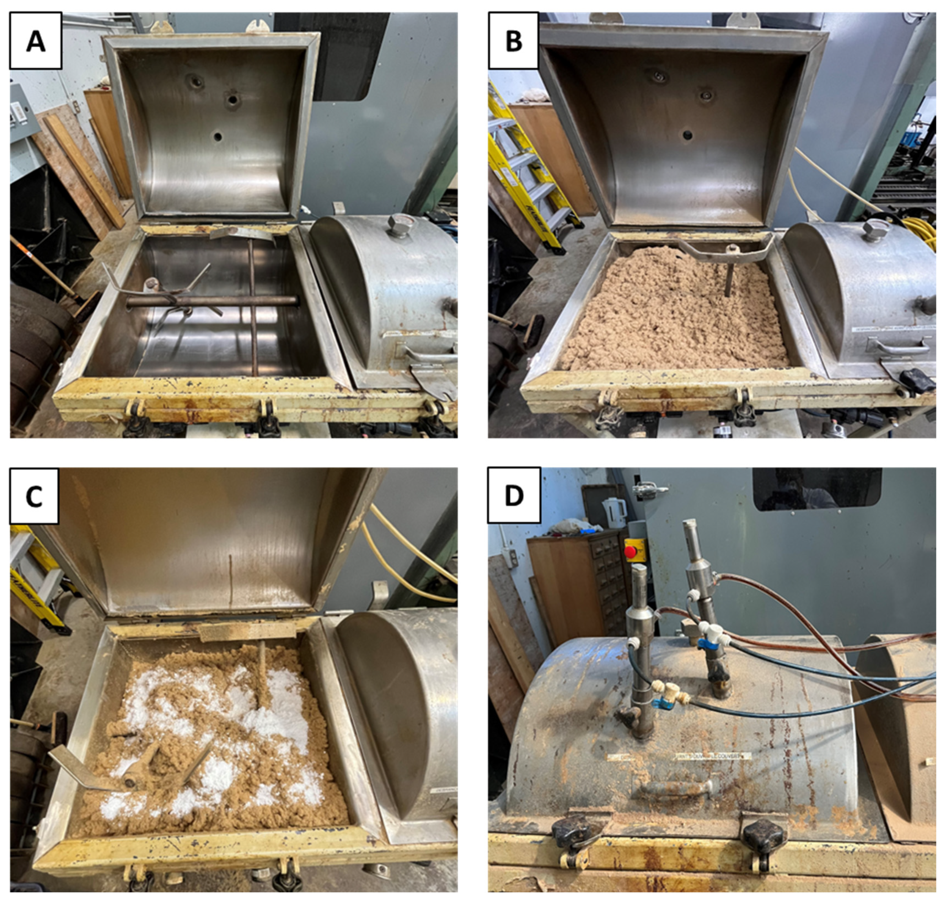
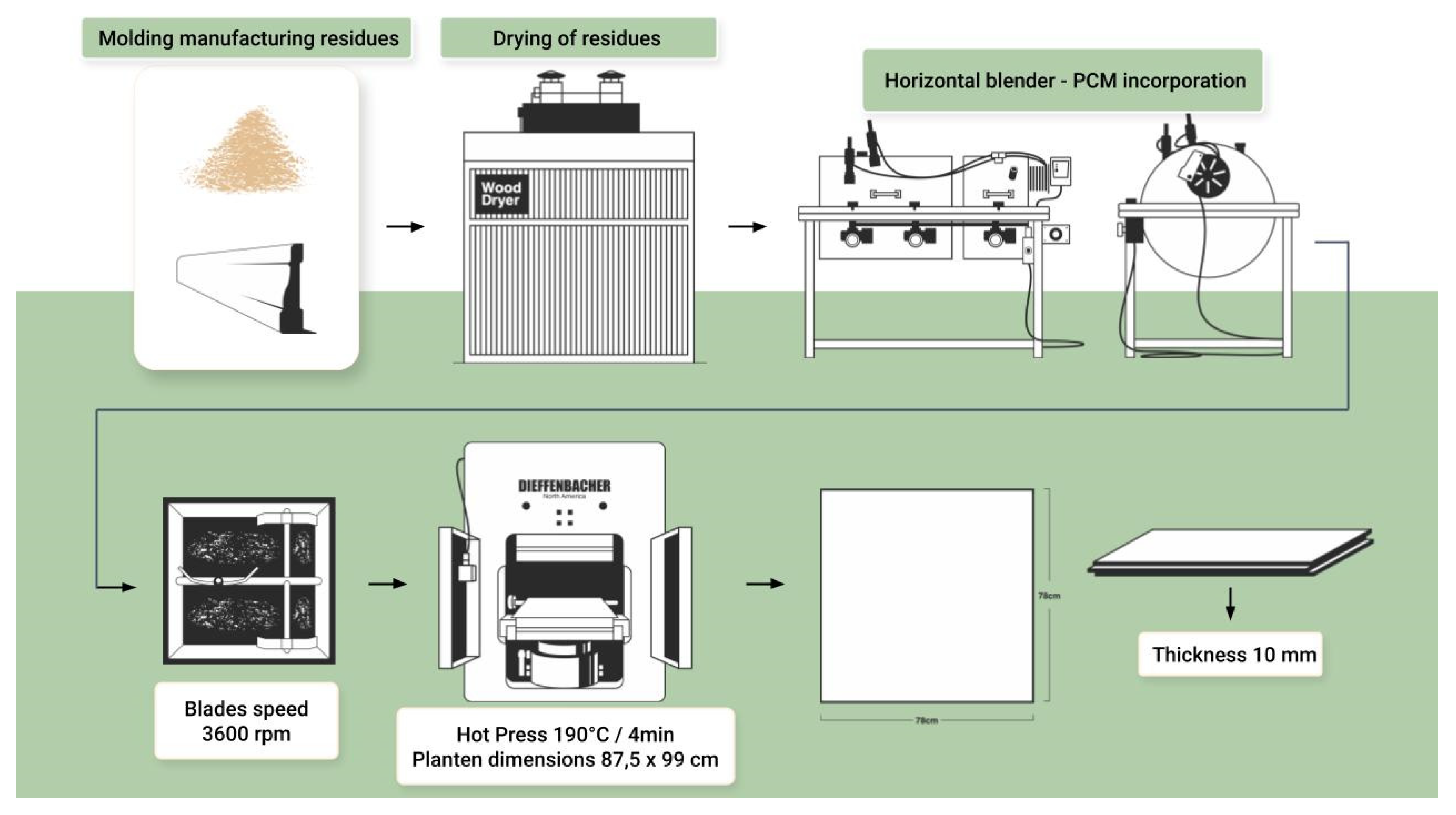
The residues were dried at 103 ± 2°C using a Cathild semi-industrial dryer until they reached a moisture content (by oven-dry weight) of 2%. The residues were then placed in a house-made horizontal blender (see
Figure 1) to blend in the adhesive and PCMs separately. The rotation speed of the blender’s blades was 3600 rpm. The adhesives and PCM1 were incorporated via nozzles connected to pipes and propelled by a pump. Air pressure of 80 psi was used to spray both adhesives and PCM1. MPCM was added directly to the mixer alongside the residues and mixed in before the adhesive was added to the blender.
Before being added, the UF adhesive was brought to 30°C, and its pH was adjusted to 7 by incorporating ammonium chloride (NH4Cl) at 25% v/v as a catalyst. The resin content used was 14% and 16% (based on the oven-dry weight of the wood) for the PF and UF adhesives, respectively. Two PCM ratios, 2% and 6%, were used for each PCM. The glued residues were placed in a mold to form a mat and then hot pressed at 190°C for 240 s using a Dieffenbacher North America hot press (Windsor, ON, Canada). After pressing, the panels were placed in a conditioning room at 20°C and 65% relative humidity until an equilibrium moisture content of 8% was reached. The final dimensions of the panels were 780 mm x 780 mm x 10 mm. The panels were not sanded. Each combination of PCM (2), adhesive (2), and PCM ratio (2) was an independent treatment (8 different combinations x 3 panel replicates each). In addition, two control panels were made, one with residues and PF adhesive, and the other with residues and UF adhesive.
Table 2 shows all the combinations considered. A detailed schematic of the panel production process can be found in
Figure 2.
2.3. Panel Characterization
2.3.1. Physical and Mechanical Properties of MDF residue-PCM panels
The vertical density profile (VDP) of the panels was assessed using a QDP-01X densitometer from Quintek Measurement Systems Inc. (Knoxville, TN, USA). The test specimens measured 50 mm x 50 mm x 10 mm. Ten specimens were tested for each panel replicate, for a total of 30 specimens per treatment. The panels’ thickness swelling and water absorption after 24 h of immersion in water were determined in accordance with ASTM standard D1037-12 [
19]. The test specimens measured 152 mm x 152 mm x 10 mm. Five specimens were tested per panel replicate, for a total of 15 specimens per treatment. The IB of the panels was determined in accordance with ASTM standard D1037-12 and using the same specimens that were used in the VDP test. The static bending modulus of elasticity (MOE) and modulus of rupture (MOR) were determined in accordance with UNE standard EN 310 [
20]. The test specimens’ width was 50 mm, and their length was 20 times the nominal panel thickness (10 mm) plus 50 mm, for a total of 250 mm. The span used was 20 times the nominal sample thickness (200 mm). Nine specimens were tested for each panel replicate, for a total of 27 specimens per treatment.
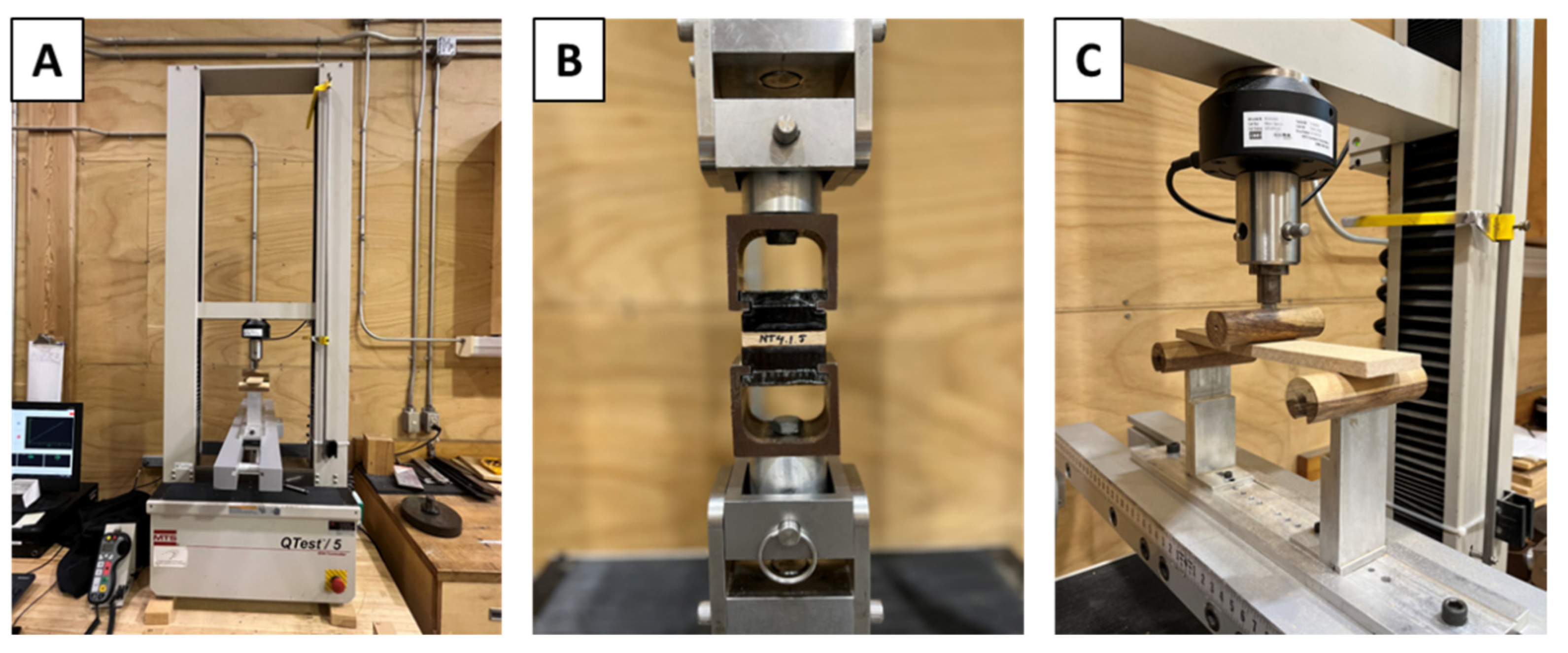
All the mechanical properties of the panels were determined using an MTS QTest-5 universal testing machine (Eden Prairie, MN, USA) with a capacity of 5 kN (see
Figure 3). The values obtained for the physical and mechanical properties (thickness swelling, IB, and static bending properties) of the panels were compared with the values specified in ANSI standard A208.2 [
21].
2.3.2. Thermal Properties of MDF Residue-PCM Panels
The specific heat of the panels was measured in accordance with ASTM standard C1784-14 [
22]. A FOX 314 heat flow meter from TA Instrument-LaserComp Inc. (Wakefield, MA, USA) was used. This test method involves taking a series of measurements to determine the thermal energy storage capacity of a test specimen over a temperature range of 5-25°C for PCM1 and 8-28°C for MPCM. The specimens were placed between two isothermal plates at set temperatures, and their heat flux was measured. The dimensions of the test specimens were 10 mm x 300 mm x 300 mm, and two specimens were tested for each treatment.
2.4. Statistical Analysis
A two-way analysis of variance was carried out on the data obtained. The analysis was performed using IBM Corp.’s SPSS version 27 statistical software (Armonk, NY, USA). The significance was determined based on < 0.05 for all the treatments considered.
3. Results
3.1. Vertical Density Profile
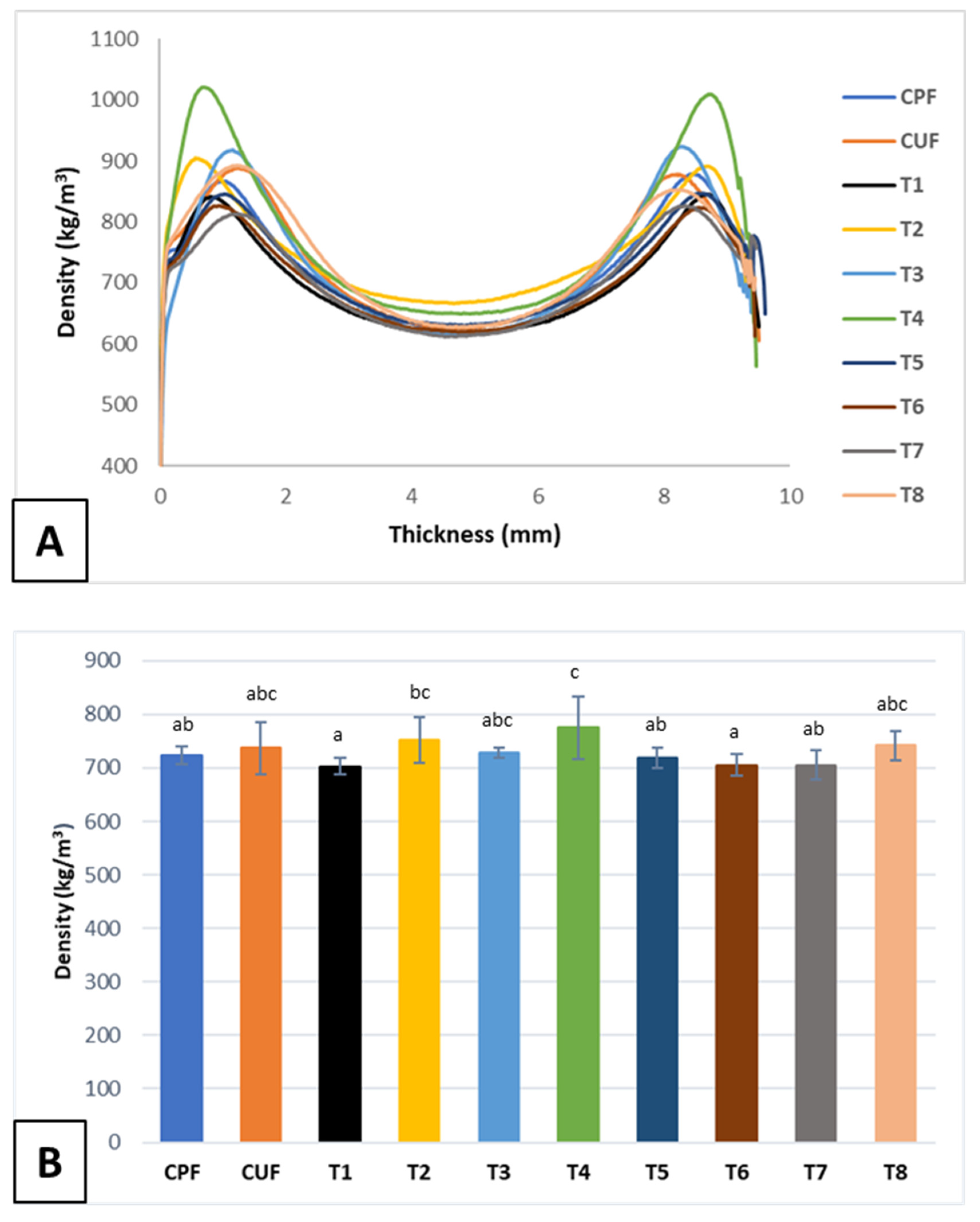
The VDP of each manufactured panel type is shown in
Figure 4A. There were minor differences in the VDPs of the panels. The density values decrease from the panel’s surface to its center. Panel T4 had the highest surface density, at 1021 kg/m
3, and a 36% lower core density, which is the most pronounced VDP. Density profile characterization serves as a determinant for assessing a panel’s mechanical performance. Panels that exhibit a flat VDP tend to have lower bending property values but a higher IB value [
23]. Hence, the pronounced VDP observed for Panel T4 indicates that it will have high MOR and MOE values. The other types of panels exhibited consistent VDPs with minor variations.
Panel T4 has the highest average density of all the panels produced, at 774.8 kg/m
3, followed by Panels T2 and T8, at 752.4 and 741.9 kg/m
3, respectively (see
Figure 4B). Tukey’s multiple comparisons test reveals statistically significant differences among the densities of the treatments. Each factor investigated—PCM type, PCM ratio, and adhesive type—has a significant influence on panel density. The interaction between the type of PCM and the PCM content also has a significant effect on density.
Table 3 shows the ANOVA
-values for panel density.
3.2. Thickness Swelling and Water Absorption
Figure 5 shows the values obtained for thickness swelling and water absorption after 24 h immersion in water. Panel T6 exhibited the least thickness swelling at 5.9%. This panel was manufactured using PF adhesive and exhibited 23% less swelling than its control panel (CPF). Panel T3, which was manufactured using UF adhesive, exhibited the most swelling, at 8.3%, which represents 4.4% less swelling than was observed for its control panel (CUF). Overall, all the treatments were found to swell less than their respective control samples (considering the adhesive type employed). The ANOVA results indicate that only the type of adhesive has a significant effect on the average swelling value of the treatments (see
Table 4). The Tukey test results suggest that there are significant differences between the treatments studied. The highest water absorption value was exhibited by Panel T1, at 59.5%, which is slightly higher than the absorption value observed for its control panel CPF. On the other hand, Panel T8 absorbed 61.5% less water than its control panel CUF. Panel T8 had the lowest absorption value of all the panels produced, at 18.9%. In contrast to swelling, water absorption is significantly affected by all the factors studied (see
Table 5). The multiple comparison test indicates the differences between the treatments evaluated are statistically significant. All panel types except T1 had lower water absorption values than those obtained for the control panels.
The thickness swelling values obtained suggest greater dimensional stability than was reported by Najahi et al. [
24], who used rapeseed stalks, which are agricultural waste, as a raw material to produce resin-free fiberboard. They used lignocellulosic nanofibers (LCNFs) instead of adhesive. The thickness swelling values they obtained were slightly higher than 10% but lower than that of a commercial fiberboard. However, their values are higher than those obtained for all the treatments developed in this study, including the control panels. Similar research was conducted by Diop et al. [
25]. They used thermomechanical pulp and lignocellulosic nanofibrils to develop MDF. They reported thickness swelling values above 20% at different pressing temperatures and various percentages of LCNF. All the thickness swelling values obtained in this study are below 1.65 mm, which is the maximum acceptable value in ANSI standard A208.2 for panels that are less than 15 mm thick.
The water absorption values obtained in this study markedly contrast with Diop et al.’s findings [
25]. They reported water absorption values of 120% to 160%, which is more than twice that of Panel T1 (59.5%). On the other hand, Boran Torun [
26] obtained water absorption values between 20% and 25% for MDF made using a mixture of beech and pine fibers. Note that while water absorption is commonly reported in the literature, it is not considered in ANSI standard A208.2. The thickness swelling and water absorption values obtained in this study demonstrate that all the fabricated panels exhibit commendable dimensional stability. Incorporating PCMs in the panels does not increase their water absorption or thickness swelling.
3.3. Internal Bond
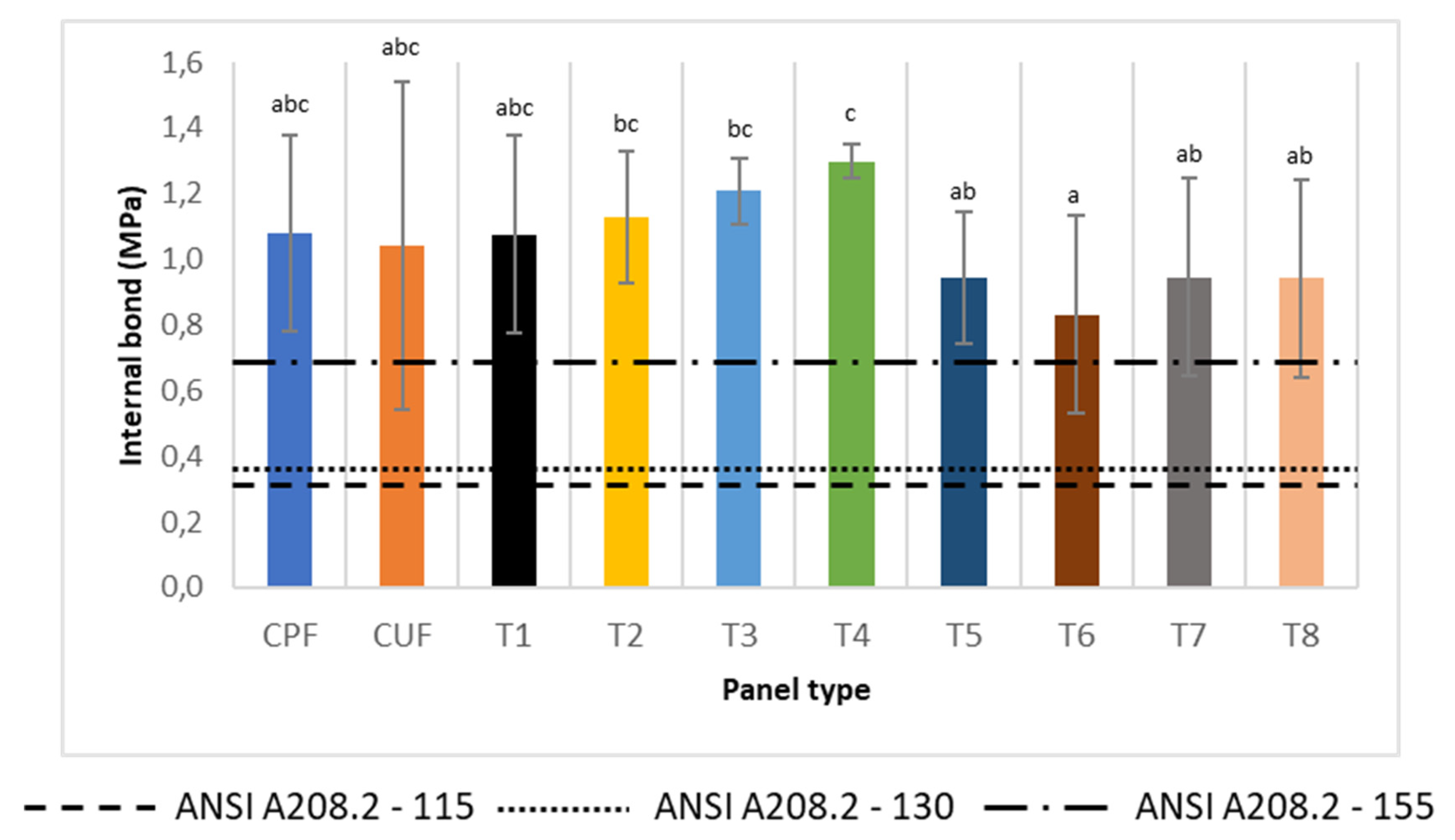
The internal bond (IB) strength of all the treatments considered, including the control panels, surpassed the minimum values set out in ANSI standard A208.2 for grades 115, 130, and 155. Panel T4 exhibited the highest IB strength, at 1.30 MPa, followed by Panel T3 and T2 at 1.21 MPa and 1.13 MPa, respectively. The lowest IB strength was observed for Panel T6 at 0.83 MPa, which is 23.2% lower than that of its control panel CPF.
Figure 6 shows that the treatments containing PCM1 demonstrated higher IB strength values than their respective control panels. Conversely, the treatments with MPCM exhibited lower IB strength values than did their respective control panels (T5 and T6 < CPF; T7 and T8 < CUF). However, the differences between the panels are not significant, and, moreover, the values remained above the minimum requirements set out in ANSI standard A208.2. According to the ANOVA results, the type of PCM and the type of adhesive significantly affect the IB strength (see
Table 6). The Tukey test results indicates that there are significant differences between the treatments evaluated.
The IB values obtained in this study are higher than those reported by Camlibel [
27], who developed fiberboard using a mixture of different types of wood and zeolite. The IB strength of Panel T6 is 25.8% higher than the highest value he obtained, while that of Panel T4 is 97% higher. Aisyah et al. [
28] reported an IB value of 0.75 MPa for MDF panels made from kenaf using different amounts of pressure during the refining process and two heating times. On the other hand, Hashim et al [
29] reported an IB value of 0.76 MPa for fiberboard with aluminum trihydrate incorporated as a fire retardant. The authors observed the panels’ IB strength decreased with an increase in the proportion of fire retardant used. In this context, Panel T6 performed better in terms of IB strength than did the panels considered by Hashim et al.
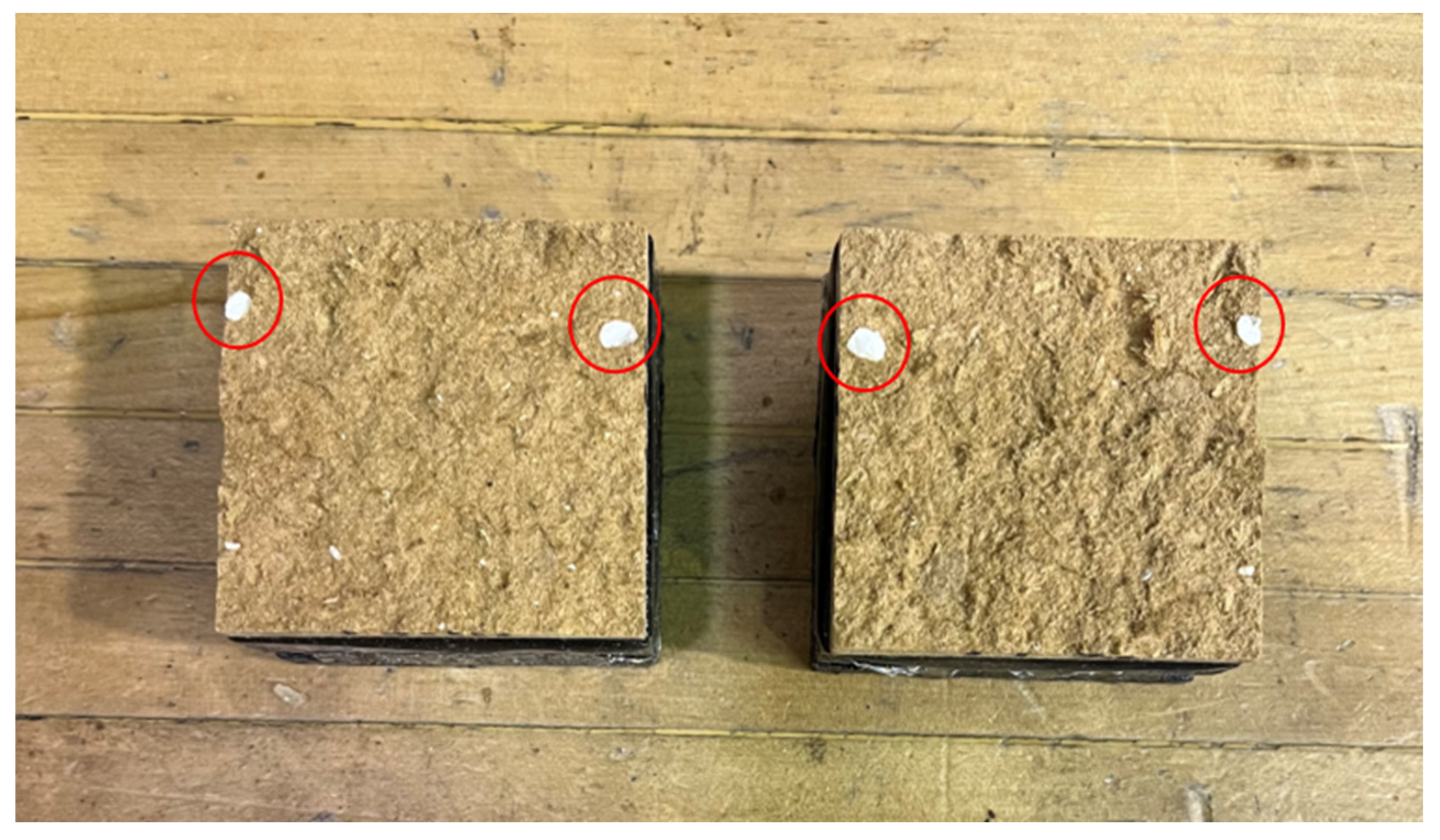
The addition of microcapsules to the panels resulted in the formation of small clusters in the panel structure (see
Figure 7). This occurrence may have disrupted adhesion between the fibers and adhesive and led to the reduced IB values observed for Panels T5-T8 in comparison with the control samples. Nonetheless, those panels’ IB values remained satisfactory (above grade 155 in ANSI standard A208.2).
3.4. Static Bending Properties
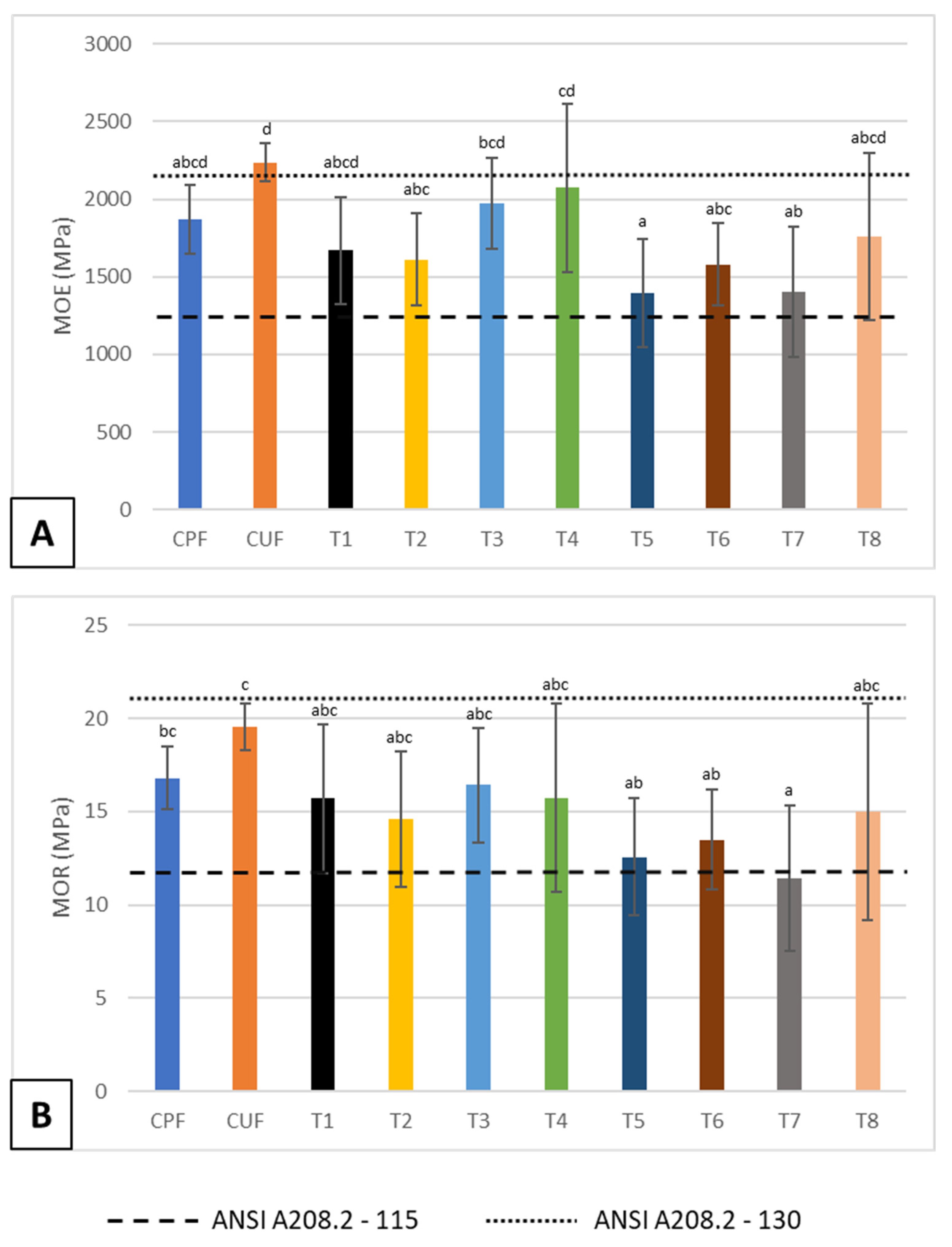
The bending MOE and MOR values of the manufactured panels are shown in
Figure 8. Panel T4 had the highest MOE of the panels developed, at 2072 MPa, followed by Panel T3, at 1974 MPa. On the other hand, Panel T5 exhibited the lowest value, at 1398 MPa, and there were significant differences between panel types according to the Tukey test results. The ANOVA results indicate that the type of PCM and type of adhesive used significantly influence the MOE (see
Table 7). According to
Figure 8A, all the treatments had average MOE values that were below the MOE of their corresponding control panel. Only the values for Panel T7 and CUF were significantly different. The panels containing MPCM exhibited lower MOE values than those made with PCM1. Moreover, the trend indicates an increase in MPCM content leads to an increase in panel bending MOE.
Panel T3 had the highest MOR value, at 16.4 MPa. This panel was made with UF adhesive and exhibited a 16% lower MOR value than did its control panel CUF. On the other hand, Panel T7 had the lowest MOR value, at 11.5 MPa, 41.4% lower than that of its control panel CUF. The ANOVA results reveal that solely the type of PCM significantly influences the MOR of the fabricated panels (see
Table 8).
A Tukey test to compare means revealed there are significant differences only between Panels T3 and T7. According to
Figure 8B, an increase in PCM1 content in the panels corresponds to a decrease in MOR value. Conversely, an increase in MPCM content increases the MOR value. Similar to the MOE trend, all the treatments had MOR values that were lower than that of their respective control sample.
The MOE and MOR values obtained in this study are similar to those reported by Jazayeri et al. [
30], who developed MDF panels with modified graphene as an additive in UF adhesive. The authors found that the MOE increases as the proportion of additive increases. Moslemi et al. [
31] developed MDF panels with a mixture of spruce and pine fibers. They used UF adhesive reinforced with cellulose nanofibers obtained from rice straw. Their MOE and MOR values (2370 MPa and 23.3 MPa, respectively) were higher than those achieved in this study.
Although the values obtained in this study are lower than those reported by other authors, all the panels met the minimum bending MOE and MOR values required by ANSI standard A208.2 for grade 115 (with the exception of Panel T7’s MOR value). No panel met the requirements for grades 130 (apart from CUF’s MOE value) or 155.
3.5. Specific Heat
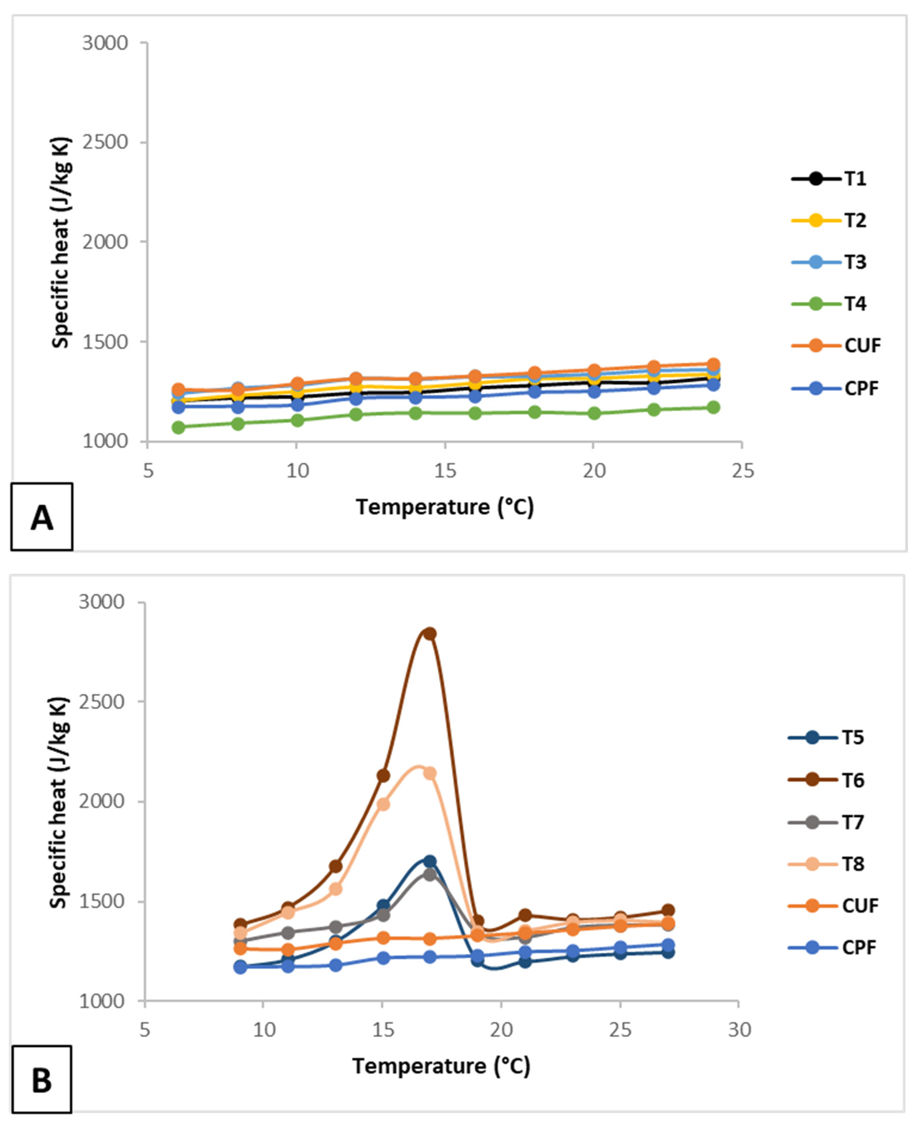
The fusion-specific heat results for the panels made with PCM1 and MPCM are shown in Figure 9A,B, respectively. No increase in specific heat was observed for the panels containing PCM1, which had similar or slightly lower specific heat values than the control panels. This observation could stem from PCM possibly being lost during pressing, or perhaps the amount of PCM1 added was insufficient to increase the specific heat of the panels. An alternative explanation could be that incorporating the PCM during the blending process instead of first impregnating the residues, as Rodriguez et al [
32] did, resulted in PCM1 not achieving a sufficiently strong bond with the fibers. It is worth mentioning that in this study, the adhesive utilized in the panel manufacturing process filled the gaps between the residue fibers. This situation reduces the likelihood of a strong bond between the residues and PCM1.
In contrast, the panels made with MPCM had higher specific heat values than the control panels (see
Figure 8B). The increase is directly proportional to the increase in the MPCM content. Notably, Panel T6 exhibited the highest specific heat value, at 2842 J/kg K, which represents a 121.5% improvement in specific heat over the control panel CPF. The next highest specific heat value belonged to Panel T8 and was 2141 J/kg K, which marked a 54.3% improvement in specific heat compared to the control panel CUF. Panels T6 and T8 both had an MPCM ratio of 6%. Furthermore, the treatments containing 2% MPCM–Panels T5 and T7–had specific heat values that were 32.7% and 17.9% greater, respectively, than those of their respective control panel.
The results demonstrate that PCMs can improve the thermal properties of fiberboard made from MDF residues. To strengthen these results, it is necessary to make panels with a higher proportion of PCM1 and MPCM. This way, it will be possible to determine the extent to which the panels’ thermal properties can be increased without affecting their physical and mechanical properties.
Figure 8.
Specific heat of the panels. A) Panels made with PCM1; B) Panels made with MPCM.
Figure 8.
Specific heat of the panels. A) Panels made with PCM1; B) Panels made with MPCM.
4. Conclusions
The composites developed in this study demonstrate that it is possible to manufacture fiberboard from MDF residues and that PCMs can be incorporated in the panels to improve their thermal properties. The panels had densities greater than or equal to 700 kg/m3. Their thickness swelled in water 23% less than did the thickness of their respective control panel, and all the panels’ thickness swelling values were below 1.65 mm, which is the value suggested by the ANSI standard A208.2. The maximum IB value obtained was 176% higher than the minimum required by the ANSI standard A208.2. PCM1 did not decrease the IB values. On the other hand, MPCM decreased the IB values slightly, but they were still 76% higher than the minimum required by the ANSI standard A208.2. Bending properties decreased with the incorporation of PCMs; Panels T1-T8 had lower bending MOR and MOE values than did their respective control panels. However, the values obtained comply with the minimum values required by the ANSI standard A208.2. PCM1 did not increase the specific heat of the panels. On the other hand, MPCM increased the specific heat of the panels by up to 121.5%.
The results of this study demonstrate the feasibility of using MDF residues as raw material for fiberboard production. Since the panels developed meet the minimum physical and mechanical property requirements in ANSI standard A208.2 for MDF and are able to store more heat than their PCM-free control panels, the panels developed can be considered for construction applications. These panels could help to regulate the indoor temperature in buildings by absorbing and releasing thermal energy.
Future research should focus on optimizing the PCM ratios to obtain better thermal properties without affecting the physical and mechanical properties of the panels. A more complete thermal characterization would make it possible to determine the amount of heat absorbed by the panels, the panels’ thermal conductivity, and how these characteristics could improve indoor thermal comfort.
Author Contributions
Conceptualization, G.E.R. and C.B.Á.; methodology, G.E.R.; formal analysis, G.E.R. and C.B.Á.; investigation, G.E.R.; resources, C.B.Á. and A.C.; data curation, G.E.R.; writing—original draft preparation, G.E.R.; writing—review and editing, G.E.R., C.B.Á. and A.C.; visualization, G.E.R. and C.B.Á.; supervision, C.B.Á. and A.C.; project administration, G.E.R. and C.B.Á.; funding acquisition, C.B.Á. All authors have read and agreed to the published version of the manuscript.
Funding
This research was funded by an internal Universidad del Bío Bío (UBB) project on innovation and development (Code I+D 22-48).
Institutional Review Board Statement
Not applicable.
Data Availability Statement
The data presented in this article are available upon reasonable request from the corresponding authors.
Acknowledgments
The authors would like to thank UBB’s Center for Biomaterials and Nanotechnology for allowing them to use its laboratories and equipment. The authors would also like to thank UBB’s Doctoral Scholarship and Research Grant and the team of the internal UBB project on innovation and development (Code: I+D 22-48).
Conflicts of Interest
The authors declare they have no conflicts of interest.
References
- Lao, W.L.; Chang, L. Comparative Life Cycle Assessment of Medium Density Fiberboard and Particleboard: A Case Study in China. Ind. Crops Prod. 2023, 205, 117443. [CrossRef]
- Farajollah Pour, M.; Hatefnia, H.; Dorieh, A.; Valizadeh Kiamahalleh, M.; Mohammadnia Afrouzi, Y. Research on Medium Density Fiberboard (MDF) Behavior against Screw Axial Withdrawal: Impact of Density and Operational Variables. Structures 2022, 39, 194–206. [CrossRef]
- Sitz, E.D.; Bajwa, D.S. The Mechanical Properties of Soybean Straw and Wheat Straw Blended Medium Density Fiberboards Made with Methylene Diphenyl Diisocyanate Binder. Ind. Crops Prod. 2015, 75, 200–205. [CrossRef]
- Song, X.; Wang, X.; Kito, K. Effects of Heating Temperature on the Properties of Bio-Board Manufactured by Using Soybean Straw. Materials (Basel). 2020, 13. [CrossRef]
- Ye, X.P.; Julson, J.; Kuo, M.; Womac, A.; Myers, D. Properties of Medium Density Fiberboards Made from Renewable Biomass. Bioresour. Technol. 2007, 98, 1077–1084. [CrossRef]
- Theng, D.; Arbat, G.; Delgado-Aguilar, M.; Ngo, B.; Labonne, L.; Mutjé, P.; Evon, P. Production of Fiberboard from Rice Straw Thermomechanical Extrudates by Thermopressing: Influence of Fiber Morphology, Water and Lignin Content. Eur. J. Wood Wood Prod. 2019, 77, 15–32. [CrossRef]
- El-Kassas, A.M.; Elsheikh, A.H. A New Eco-Friendly Mechanical Technique for Production of Rice Straw Fibers for Medium Density Fiberboards Manufacturing. Int. J. Environ. Sci. Technol. 2021, 18, 979–988. [CrossRef]
- Zhang, W.; Sun, H.; Zhu, C.; Wan, K.; Zhang, Y.; Fang, Z.; Ai, Z. Mechanical and Water-Resistant Properties of Rice Straw Fiberboard Bonded with Chemically-Modified Soy Protein Adhesive. RSC Adv. 2018, 8, 15188–15195. [CrossRef]
- Puspaningrum, T.; Haris, Y.H.; Sailah, I.; Yani, M.; Indrasti, N.S. Physical and Mechanical Properties of Binderless Medium Density Fiberboard (MDF) from Coconut Fiber. IOP Conf. Ser. Earth Environ. Sci. 2020, 472, 012011. [CrossRef]
- Araújo Junior, C.P.; Coaquira, C.A.C.; Mattos, A.L.A.; de Souza Filho, M. de S.M.; Feitosa, J.P. de A.; Morais, J.P.S. de; de Freitas Rosa, M. Binderless Fiberboards Made from Unripe Coconut Husks. Waste and Biomass Valorization 2018, 9, 2245–2254. [CrossRef]
- Pugazhenthi, N.; Anand, P. Mechanical and Thermal Behavior of Hybrid Composite Medium Density Fiberboard Reinforced with Phenol Formaldehyde. Heliyon 2021, 7, e08597. [CrossRef]
- Zimmer, A.; Angie Lunelli Bachmann, S. Challenges for Recycling Medium-Density Fiberboard (MDF). Results Eng. 2023, 19, 101277. [CrossRef]
- Rivas, N. Conversación Personal Con El Subgerente de Tecnología de Procesos de Investigación y Desarrollo de MASISA; Concepción, Chile, 2023;
- Fernández, V.; Valderrama-Ulloa, C.; Rouault, F.; Schmitt, C.; Del Río, R.; Vasco, D. Thermal and Mechanical Analysis of Plywood Boards Thermally Enhanced with Phase Change Materials. IOP Conf. Ser. Earth Environ. Sci. 2020, 503. [CrossRef]
- Qi, C.; Zhang, F.; Mu, J.; Zhang, Y.; Yu, Z. Enhanced Mechanical and Thermal Properties of Hollow Wood Composites Fi Lled with Phase-Change Material. J. Clean. Prod. 2020, 256, 120373. [CrossRef]
- Can, A. Preparation, Characterization, and Thermal Properties of Microencapsulated Palmitic Acid with Ethyl Cellulose Shell as Phase Change Material Impregnated Wood. J. Energy Storage 2023, 66, 107382. [CrossRef]
- Li, Y.; Wang, B.; Zhang, W.; Zhao, J.; Fang, X.; Sun, J.; Xia, R.; Guo, H.; Liu, Y. Processing Wood into a Phase Change Material with High Solar-Thermal Conversion Efficiency by Introducing Stable Polyethylene Glycol-Based Energy Storage Polymer. Energy 2022, 254, 124206. [CrossRef]
- Rodríguez, G.E.; Bustos Ávila, C.; Cloutier, A. Use of Phase Change Materials in Wood and Wood- Based Composites for Thermal Energy Storage: A Review. BioResources 2023, 18, 8781–8805. [CrossRef]
- ASTM D1037 - 12 Standard Test Methods for Evaluating Properties of Wood-Base Fiber and Particle Panel Materials. ASTM Int. 2020, 1–31.
- UNE UNE-EN 310 Tableros Derivados de La Madera. Determinación Del modulo de Elasticidad En Flexión y de La Resistencia a La Flexión. 1994.
- ANSI A208.2 Medium Density Fiberboard (MDF) For Interior Applications. Am. Natl. Stand. 2016.
- ASTM ASTM C1784 Standard Test Method for Using a Heat Flow Meter Apparatus for Measuring Thermal Storage Properties of Phase Change Materials and Products. ASTM Int. 2016.
- Moreno-Anguiano, O.; Cloutier, A.; Rutiaga-Quiñones, J.G.; Wehenkel, C.; Rosales-Serna, R.; Rebolledo, P.; Hernández-Pacheco, C.E.; Carrillo-Parra, A. Use of Agave Durangensis Bagasse Fibers in the Production of Wood-Based Medium Density Fiberboard (MDF). Forests 2022, 13. [CrossRef]
- Najahi, A.; Aguado, R.J.; Tarrés, Q.; Boufi, S.; Delgado-Aguilar, M. Harvesting Value from Agricultural Waste: Dimensionally Stable Fiberboards and Particleboards with Enhanced Mechanical Performance and Fire Retardancy through the Use of Lignocellulosic Nanofibers. Ind. Crops Prod. 2023, 204. [CrossRef]
- Diop, C.I.K.; Tajvidi, M.; Bilodeau, M.A.; Bousfield, D.W.; Hunt, J.F. Evaluation of the Incorporation of Lignocellulose Nanofibrils as Sustainable Adhesive Replacement in Medium Density Fiberboards. Ind. Crops Prod. 2017, 109, 27–36. [CrossRef]
- Boran Torun, S. Investigation of the Properties of Fiberboards Made from Microcrystalline Cellulose and Antimony Trioxide Added Melamine Formaldehyde Adhesive. Int. J. Adhes. Adhes. 2022, 113, 103084. [CrossRef]
- Camlibel, O. Mechanical and Formaldehyde-Related Properties of Medium Density Fiberboard with Zeolite Additive. BioResources 2020, 15, 7918–7932. [CrossRef]
- Aisyah, H.A.; Paridah, M.T.; Sahri, M.H.; Anwar, U.M.K.; Astimar, A.A. Properties of Medium Density Fibreboard (MDF) from Kenaf (Hibiscus Cannabinus L.) Core as Function of Refining Conditions. Compos. Part B 2013, 44, 592–596. [CrossRef]
- Hashim, R.; Sulaiman, O.; Kumar, R.N.; Tamyez, P.F.; Murphy, R.J.; Ali, Z. Physical and Mechanical Properties of Flame Retardant Urea Formaldehyde Medium Density Fiberboard. J. Mater. Process. Technol. 2009, 209, 635–640. [CrossRef]
- Jazayeri, R.; Najafi, S.K.; Younesi, H. Modified Graphene as Potential Additive for Urea Formaldehyde (UF) Resin in Medium Density Fiberboard (MDF) Manufacturing. Int. J. Adhes. Adhes. 2023, 126, 103448. [CrossRef]
- Moslemi, A.; Zolfagharlou koohi, M.; Behzad, T.; Pizzi, A. Addition of Cellulose Nanofibers Extracted from Rice Straw to Urea Formaldehyde Resin; Effect on the Adhesive Characteristics and Medium Density Fiberboard Properties. Int. J. Adhes. Adhes. 2020, 99, 102582. [CrossRef]
- Rodríguez, G.E.; Bustos Ávila, C.; Romero, R.; Cloutier, A. Impregnation of Medium-Density Fiberboard Residues with Phase Change Materials for Efficient Thermal Energy Storage. Forests 2023, 14, 2175. [CrossRef]
|
Disclaimer/Publisher’s Note: The statements, opinions and data contained in all publications are solely those of the individual author(s) and contributor(s) and not of MDPI and/or the editor(s). MDPI and/or the editor(s) disclaim responsibility for any injury to people or property resulting from any ideas, methods, instructions or products referred to in the content. |
© 2024 by the authors. Licensee MDPI, Basel, Switzerland. This article is an open access article distributed under the terms and conditions of the Creative Commons Attribution (CC BY) license (http://creativecommons.org/licenses/by/4.0/).
