Submitted:
18 April 2024
Posted:
18 April 2024
You are already at the latest version
Abstract
Keywords:
1. Introduction
2. Magnetic Field Subdomain Model
3.1. Magnetic Vector Equation in Subdomain
3.2. Inductance Equation Based on Subdomain Method
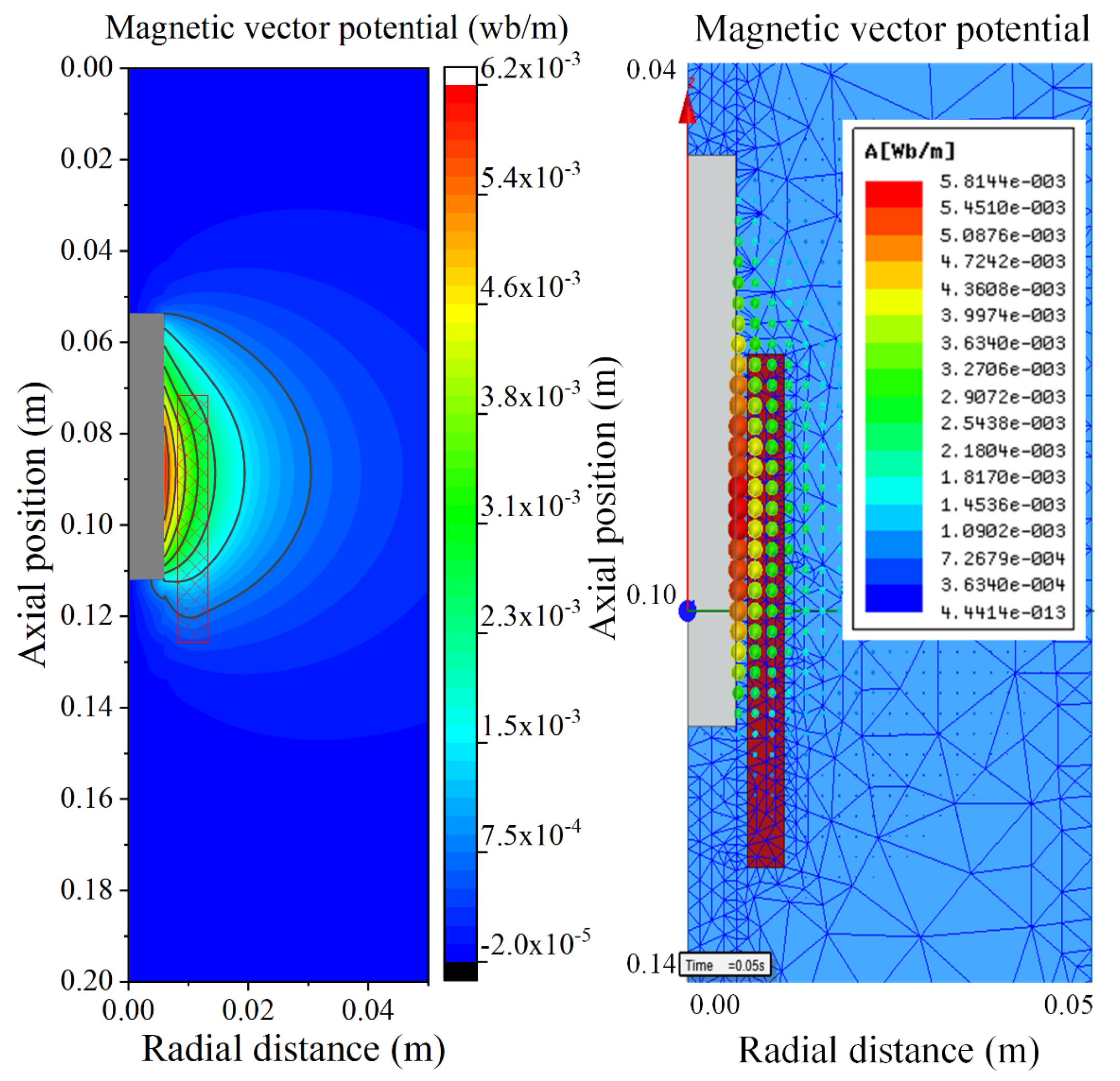
3.3. Electromagnetic Characteristics Analysis of the Push-Pull Electromagnet
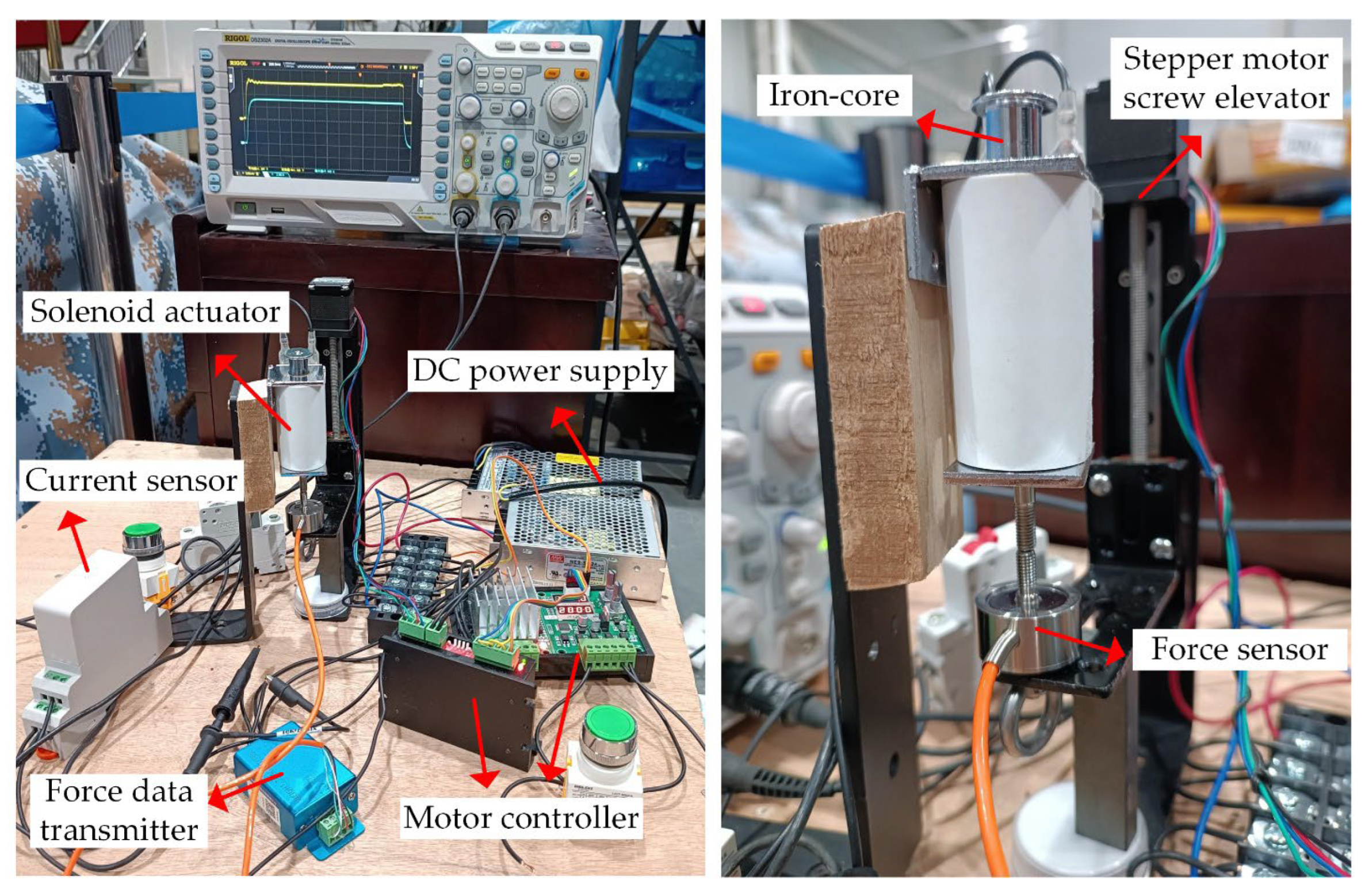
3. Experimental Platform Construction and Algorithm Verification
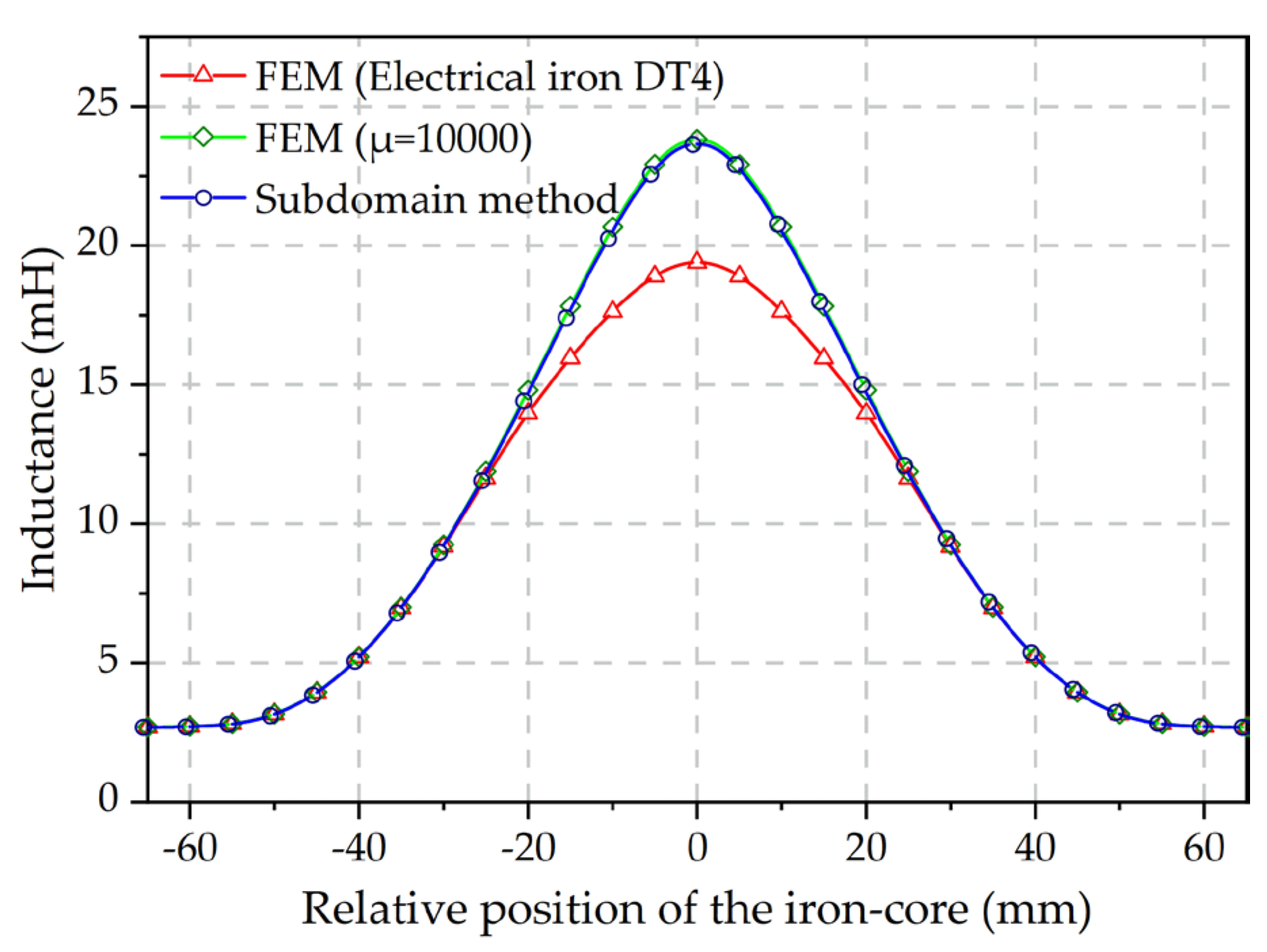
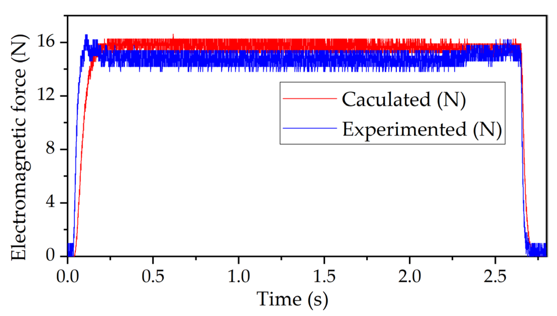
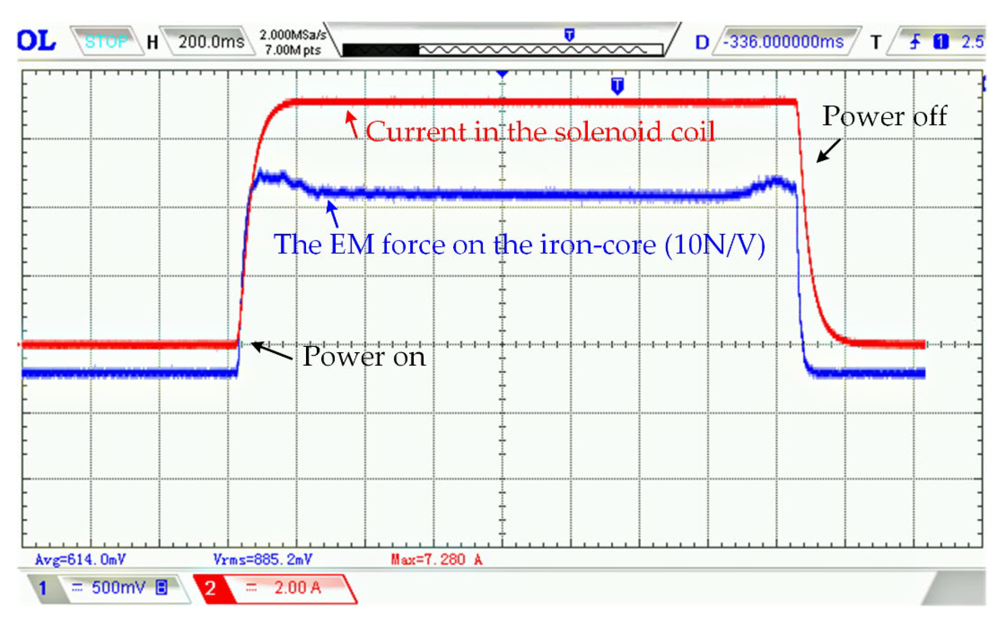
3.1. Verification of the Calculated Electromagnetic Force
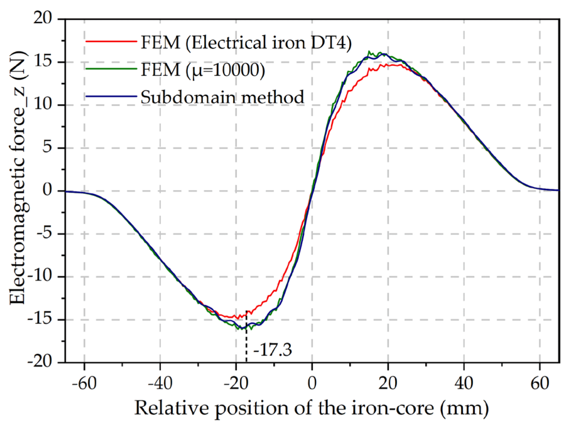
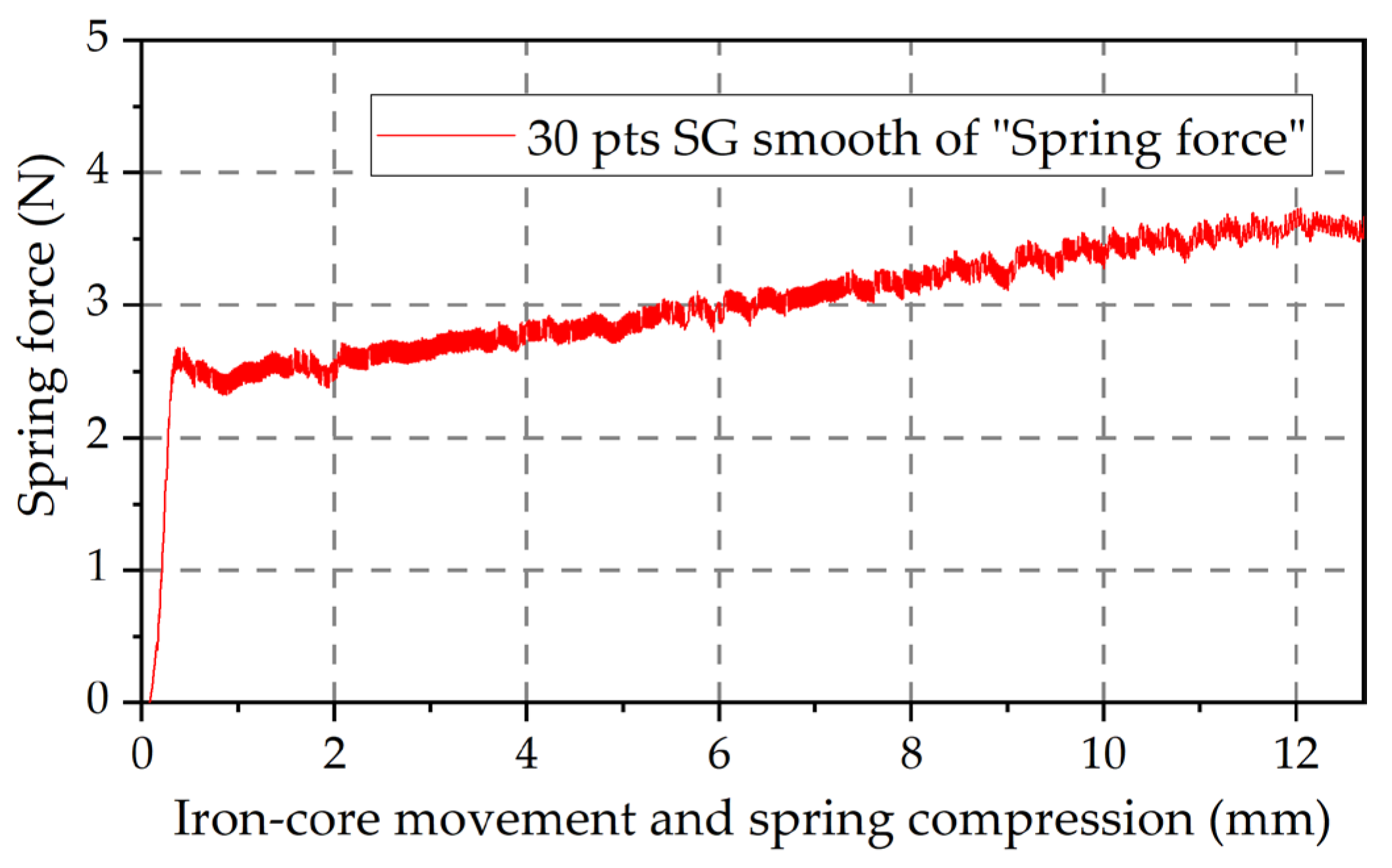
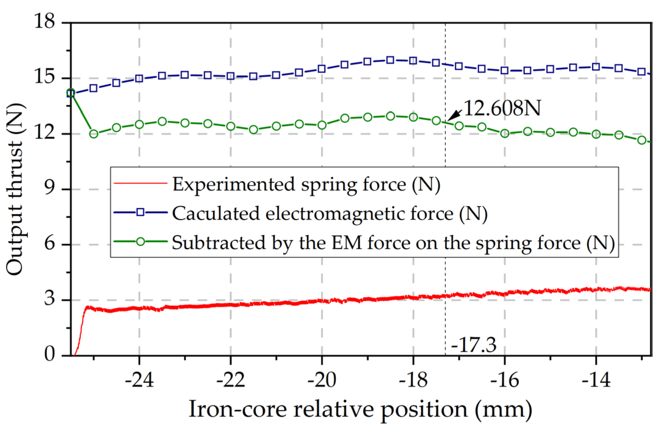
3.2. Verification of the Calculated Output Thrust
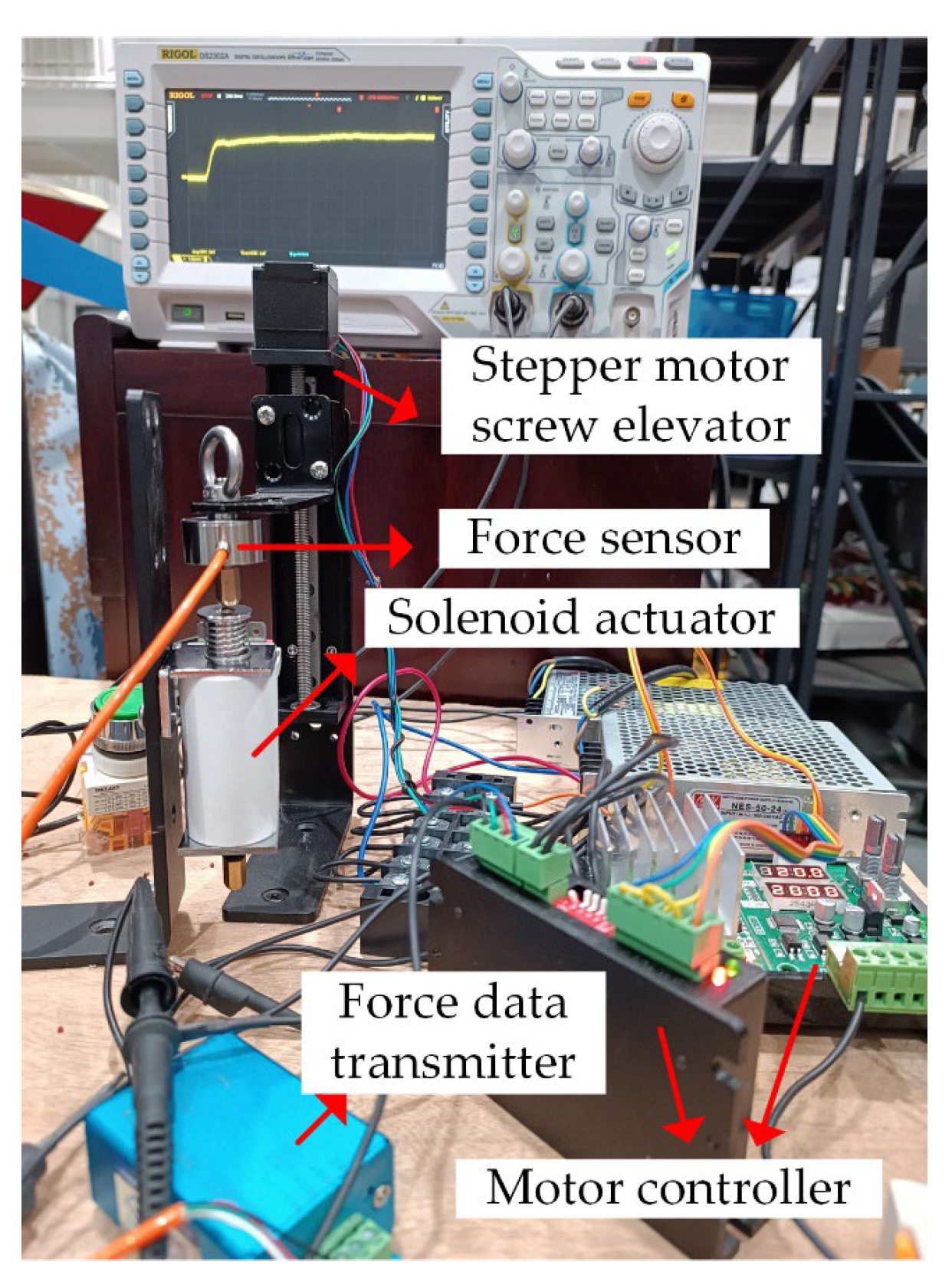
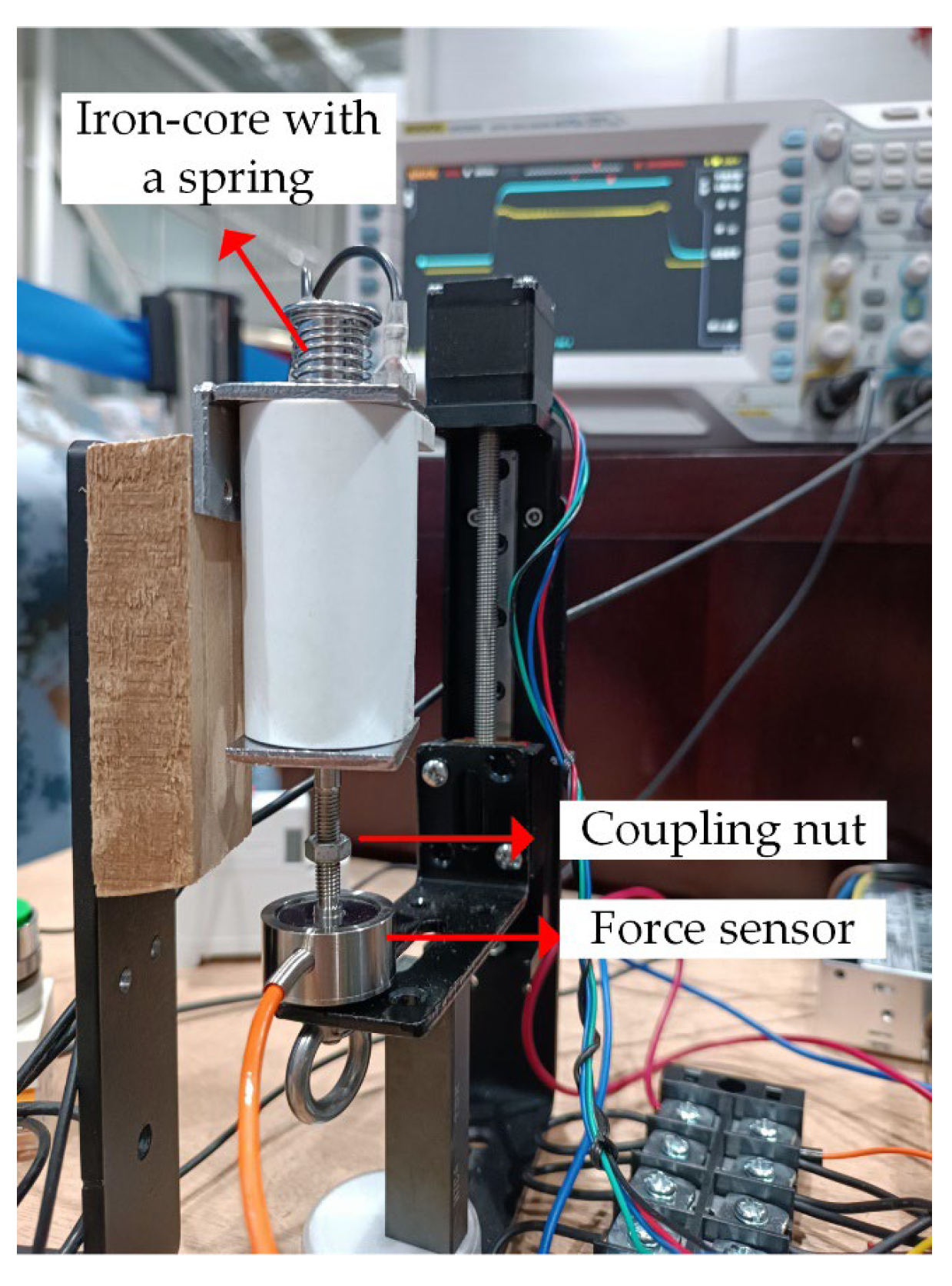
5. Conclusions
Author Contributions
Funding
Data Availability Statement
Acknowledgments
Conflicts of Interest
References
- Afshar, S.; Khamesee, M.B.; Khajepour, A. Optimal configuration for electromagnets and coils in magnetic actuators. IEEE Trans. Magn. 2012, 49, 1372–1381. [Google Scholar] [CrossRef]
- Hassannia, A.; Abedi, K. Optimal switching scheme for multistage reluctance coilgun. IEEE Trans. Plasma Sci. 2021, 49, 1241–1246. [Google Scholar] [CrossRef]
- Lu, M.; Zhang, J.; Yi, X.; Zhuang, Z. Advanced mathematical calculation model of single-stage RCG. IEEE Tran. Plasma Sci. 2022, 50, 1026–1031. [Google Scholar] [CrossRef]
- Lequesne, B. Automotive electrification: The nonhybrid story. IEEE Trans. Transp. Electr. 2015, 1, 40–53. [Google Scholar] [CrossRef]
- Wu, S.; Zhao, X.; Li, C.; Jiao, Z.; Qu, F. Multiobjective optimization of a hollow plunger type solenoid for high speed on/off valve. IEEE Trans. Ind. Electron. 2017, 65, 3115–3124. [Google Scholar] [CrossRef]
- Li, K.; Luo, C.; Niu, F.; Li, C.; Tong, M.; Wu, Y. A new magnetic release design with high anti-interference capability. IEEE Trans. Magn. 2021, 57, 1–9. [Google Scholar] [CrossRef]
- Cao, Z.; Zuo, Y. Electromagnetic riveting technique and its applications. Chinese J. Aeronaut. 2020, 33, 5–15. [Google Scholar] [CrossRef]
- Hogan, P.H.; Van de Ven, J.D. Dynamic modeling of a linear electromagnetic piston pump. in Proc. ASME/BATH 2017 Symp. Fluid Power Motion Control Amer. Soc. Mech. Eng., 2017, V001T01A062.
- Barbetta, M.; Boesso, A.; Branz, F.; Carron, A.; Olivieri, L.; Prendin, J.; Francesconi, A. ARCADE-R2 experiment on board BEXUS 17 stratospheric balloon. CEAS Space J. 2015, 7, 347–358. [Google Scholar] [CrossRef]
- Goeller, M.; Oberlaender, J.; Uhl, K.; Roennau, A. , Dillmann, R. Modular robots for on-orbit satellite servicing. In IEEE international conference on robotics and biomimetics (ROBIO), 2012, 2018-2023.
- Song, C.W.; Lee, S.Y. Design of a solenoid actuator with a magnetic plunger for miniaturized segment robots. Applied sciences 2015, 5, 595–607. [Google Scholar] [CrossRef]
- Alizadeh, H.V.; Boulet, B. Analytical calculation of the magnetic vector potential of an axisymmetric solenoid in the presence of iron parts. IEEE Trans. Magn. 2015, 52, 1–4. [Google Scholar] [CrossRef]
- Liang, P.; Chai, F.; Bi, Y.; Pei, Y.; Cheng, S. Analytical model and design of spoke-type permanent-magnet machines accounting for saturation and nonlinearity of magnetic bridges. J. Magn. Magn. Mater. 2016, 417, 389–396. [Google Scholar] [CrossRef]
- Lubin, T.; Berger, K.; Rezzoug, A. Inductance and force calculation for axisymmetric coil systems including an iron core of finite length. Progress In Electromagnetics Research B 2012, 41, 377–396. [Google Scholar] [CrossRef]
- Elbaa, M.K.; Berger, B.; Douine, M. Halit, Bentridi S.E. Analytical modeling of an inductor in a magnetic circuit for pulsed field magnetization of HTS bulks. IEEE Trans. Appl. Supercon. 2018, 28, 1–6. [Google Scholar] [CrossRef]
- Luo, Y. Field and inductance calculations for coaxial circular coils with magnetic cores of finite length and constant permeability. IET Electr. Power App. 2017, 11, 1254–1264. [Google Scholar] [CrossRef]
- Jebelli, A.; Mahabadi, A.; Yagoub, M.C.; Chaoui, H. Magnetic force calculation between magnets and coil. International Journal of Physics 2020, 8, 71–80. [Google Scholar] [CrossRef]
- Pankrac, V.; Kracek, J. Simple algorithms for the calculation of the intensity of the magnetic field of current loops and thin-wall air coils of a general shape using magnetic dipoles. IEEE Trans. Magn. 2012, 48, 4767–4778. [Google Scholar] [CrossRef]
- Kojooyan-Jafari, H.; Monjo, L.; Córcoles, F.; Pedra, J. Parameter estimation of wound-rotor induction motors from transient measurements. IEEE Trans. Energy Conver. 2014, 29, 300–308. [Google Scholar]
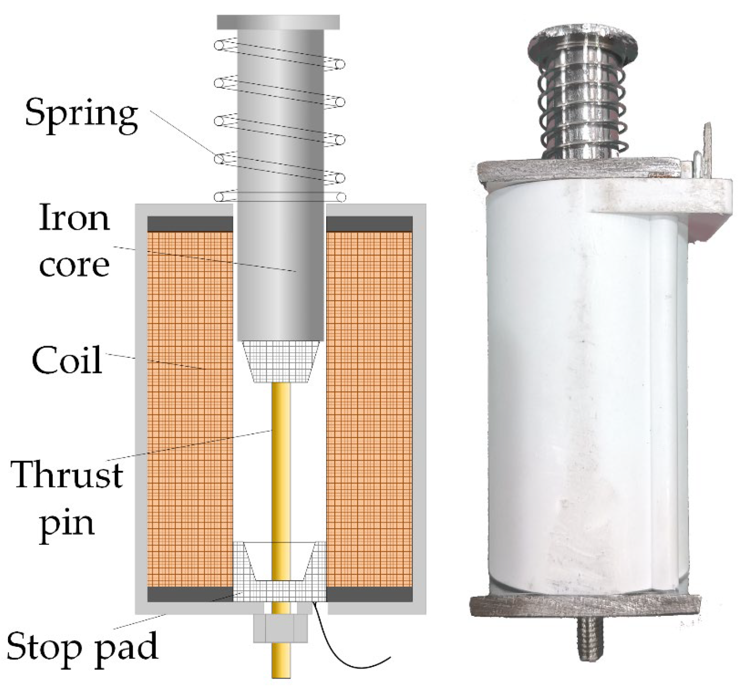
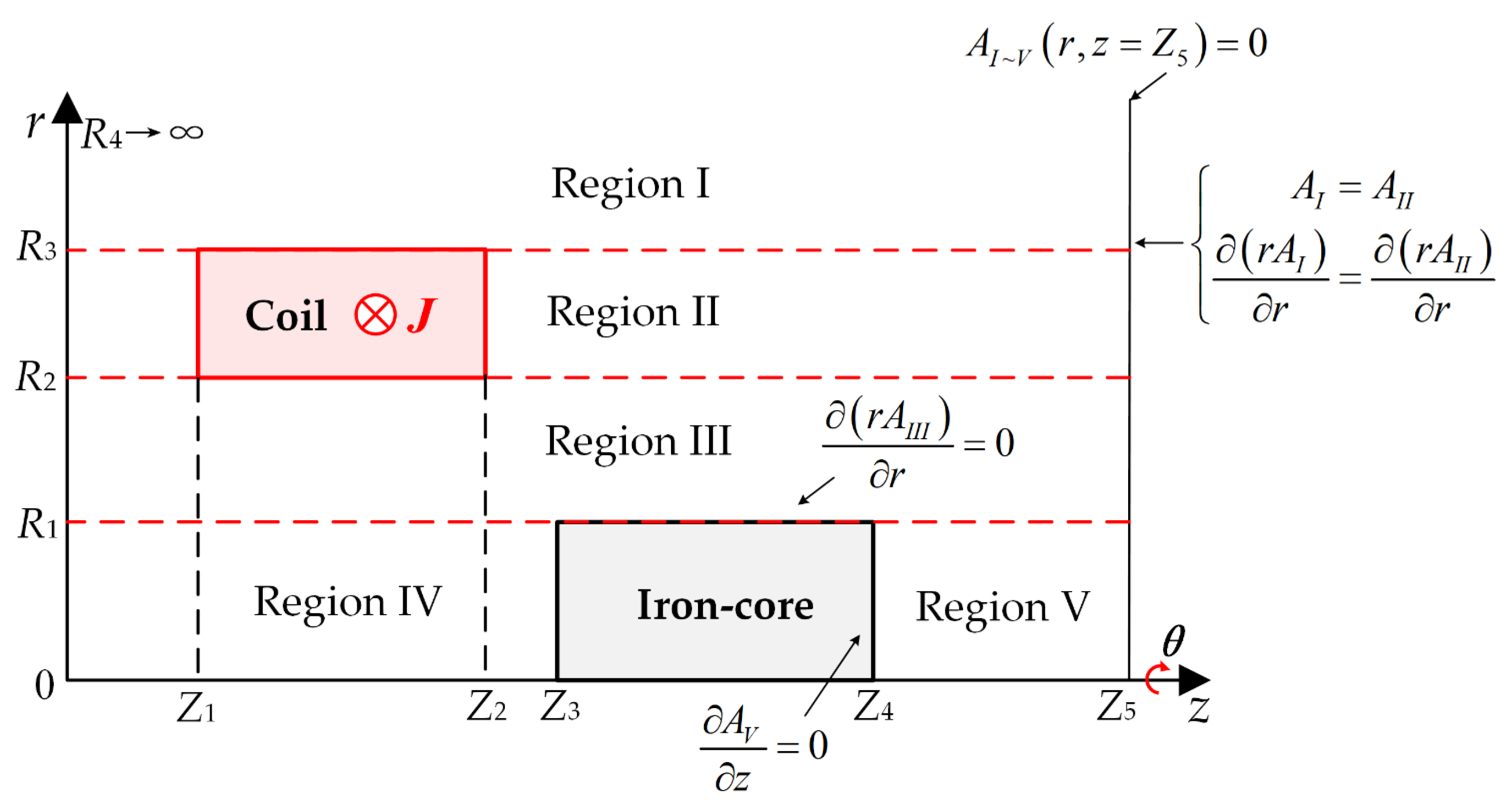

| Symbol | Quantity | Value |
|---|---|---|
| R1 | Radius of the iron | 5.9 mm |
| R2 | Inner Radius of the coil | 7.4 mm |
| R3 | Outer Radius of the coil | 12.0 mm |
| R4 | Radial boundary of the solution domain | 50.0 mm |
| L | Axial length of the coil | 52 mm |
| l | Axial length of the iron-core | 58 mm |
| h | Relative displacement of coil and armature center | variable |
| Z1 | Axial position of the coil (left side) | 74 mm |
| Z3 | Axial position of the iron-core (left side) | 53.7 mm |
| Z5 | Outer boundary of the coil | 200 mm |
| N | Number of turns of the coil | 720 |
| I | Excitation current of the coil | 7.24 A |
| Nmax | Number of harmonic terms in Region ⅠⅡ and Ⅲ | 40 |
| Kmax | Number of harmonic terms in Region Ⅳ and Ⅴ | 40 |
Disclaimer/Publisher’s Note: The statements, opinions and data contained in all publications are solely those of the individual author(s) and contributor(s) and not of MDPI and/or the editor(s). MDPI and/or the editor(s) disclaim responsibility for any injury to people or property resulting from any ideas, methods, instructions or products referred to in the content. |
© 2024 by the authors. Licensee MDPI, Basel, Switzerland. This article is an open access article distributed under the terms and conditions of the Creative Commons Attribution (CC BY) license (http://creativecommons.org/licenses/by/4.0/).


