Submitted:
19 April 2024
Posted:
19 April 2024
You are already at the latest version
Abstract
Keywords:
1. Introduction
2. Computational Details
2.1. Classical Molecular Dynamics (cMD) Simulations
2.2. AIMD and RMD Simulations
3. Results and Discussion
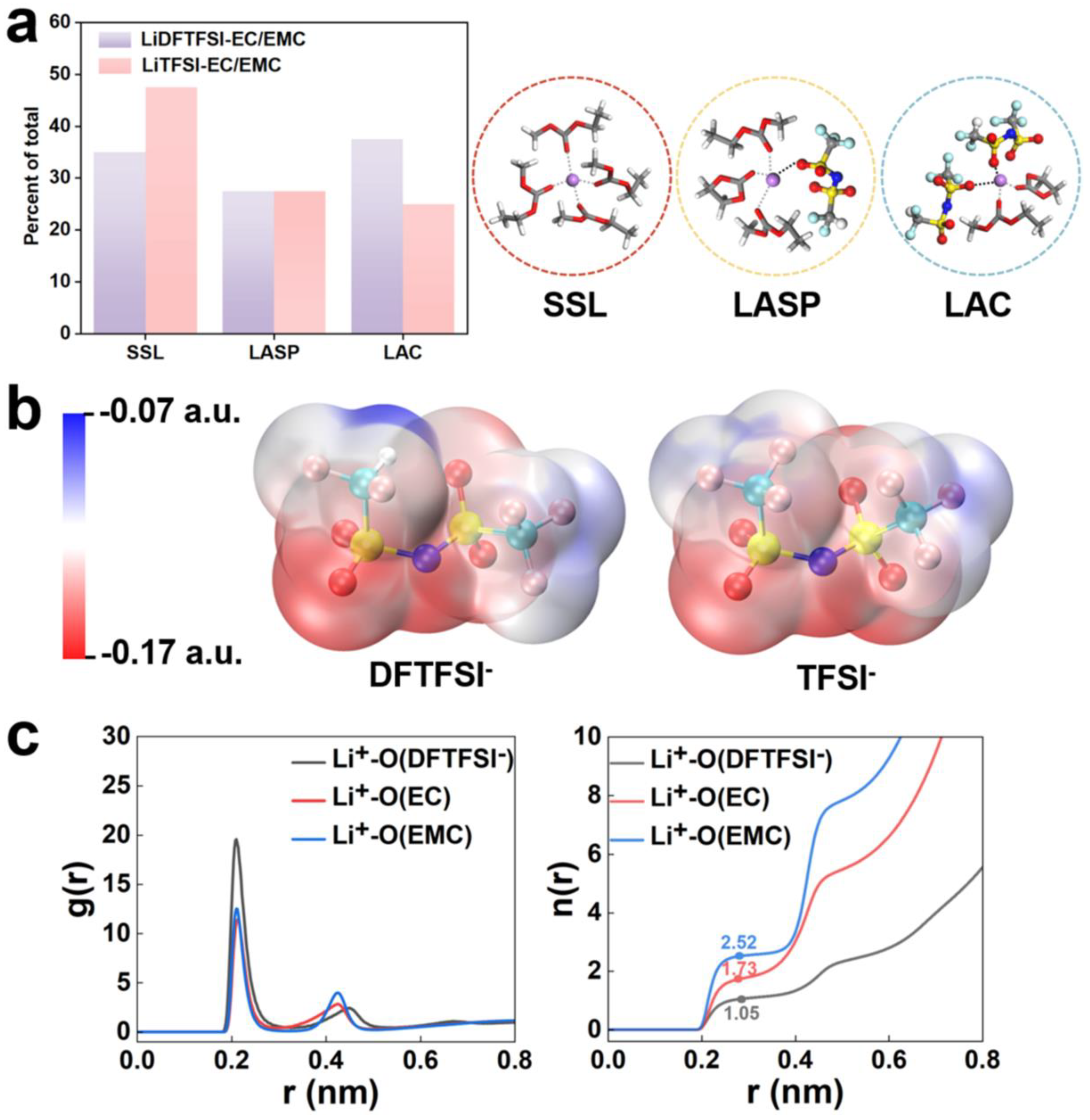
3.1. Electrolyte Solvation Structure Analysis
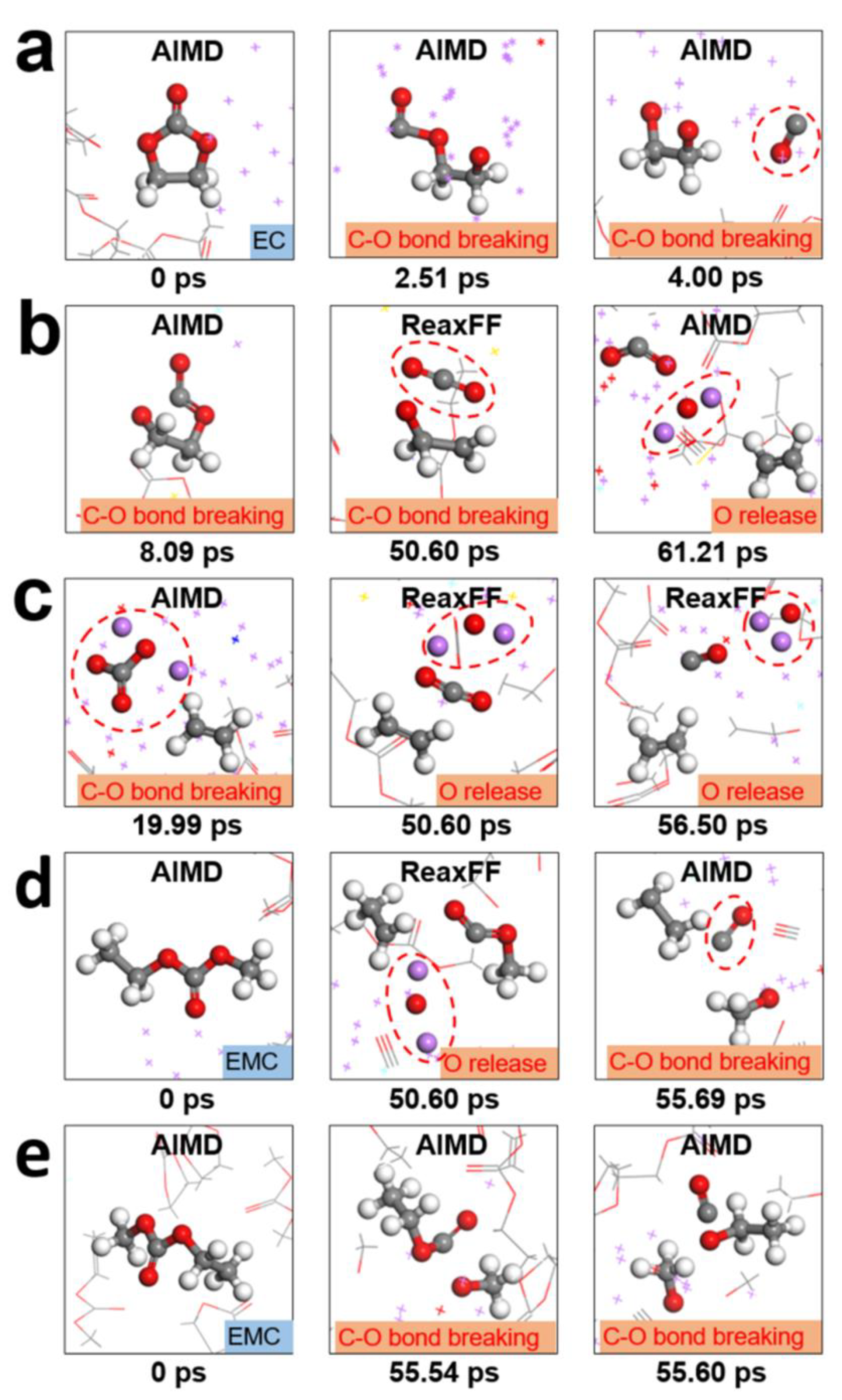
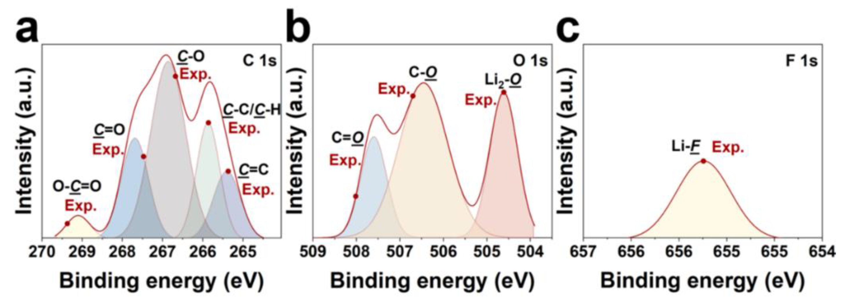
3.2. Underlying mechanism of electrolyte reduction and SEI formation
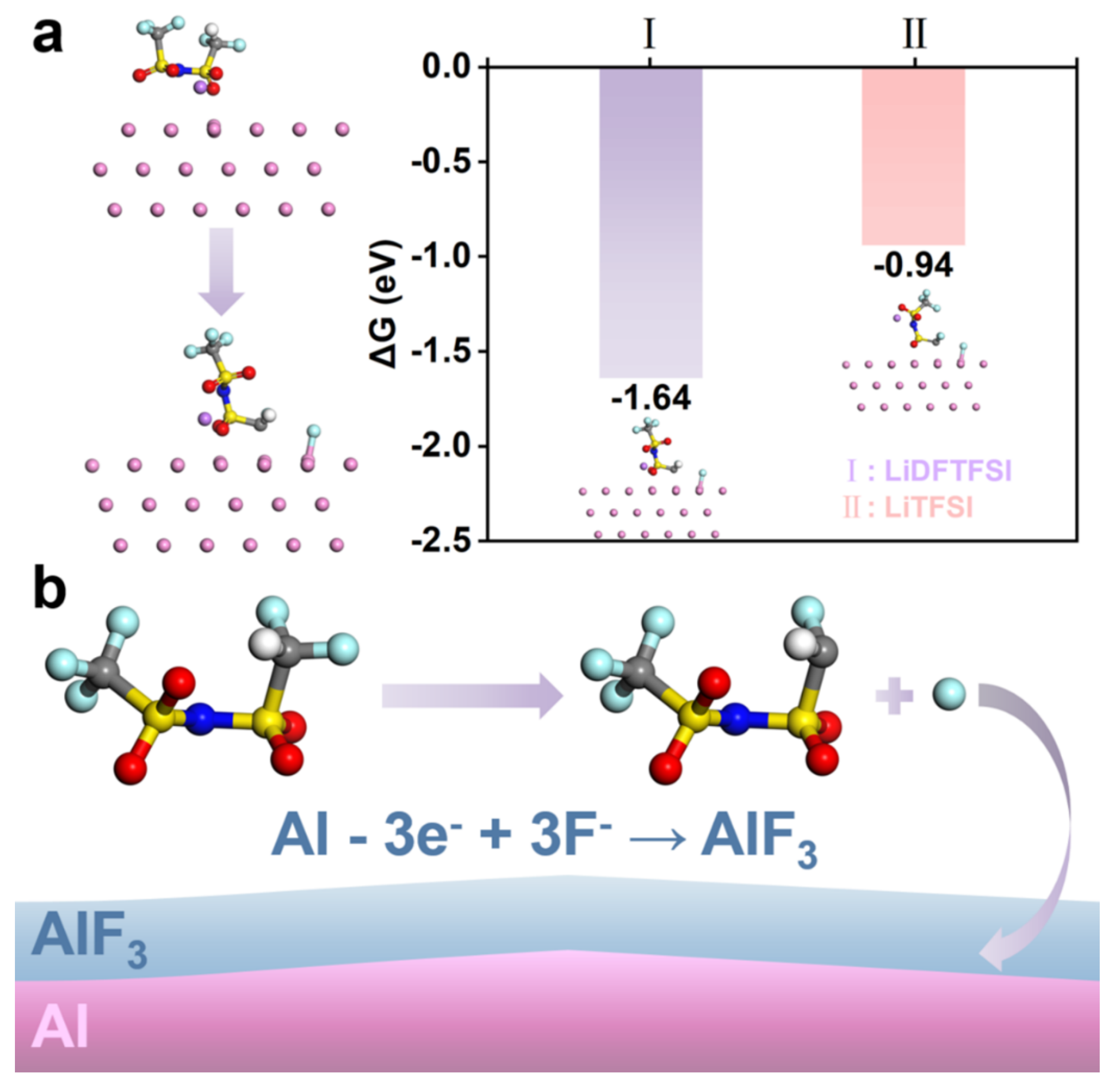
3.3. DFTFSI–Passivated Al
4. Conclusions
Supplementary Materials
Author Contributions
Data Availability Statement
Acknowledgments
Conflicts of Interest
References
- Winter, M.; Barnett, B.; Xu, K. Before Li ion batteries. Chem. Rev. 2018, 118, 11433-11456. [CrossRef]
- Larcher, D.; Tarascon, J.M. Towards greener and more sustainable batteries for electrical energy storage. Nat. Chem. 2015, 7, 19-29. [CrossRef]
- Lin, D.; Liu, Y.; Cui, Y. Reviving the lithium metal anode for high-energy batteries. Nat. Nanotechnol. 2017, 12, 194-206. [CrossRef]
- Dunn, B.; Kamath, H.; Tarascon, J.-M. Electrical energy storage for the grid: a battery of choices. Science 2011, 334, 928-935. [CrossRef]
- Wang, H.; Yu, Z.; Kong, X.; Kim, S.C.; Boyle, D.T.; Qin, J.; Bao, Z.; Cui, Y. Liquid electrolyte: The nexus of practical lithium metal batteries. Joule 2022, 6, 588-616. [CrossRef]
- Li, M.; Wang, C.; Davey, K.; Li, J.; Li, G.; Zhang, S.; Mao, J.; Guo, Z. Recent progress in electrolyte design for advanced lithium metal batteries. SmartMat 2023, 4, e1185. [CrossRef]
- Hobold, G.M.; Lopez, J.; Guo, R.; Minafra, N.; Banerjee, A.; Shirley Meng, Y.; Shao-Horn, Y.; Gallant, B.M. Moving beyond 99.9% coulombic efficiency for lithium anodes in liquid electrolytes. Nat. Energy 2021, 6, 951-960. [CrossRef]
- Liu, J.; Bao, Z.; Cui, Y.; Dufek, E.J.; Goodenough, J.B.; Khalifah, P.; Li, Q.; Liaw, B.Y.; Liu, P.; Manthiram, A.; et al. Pathways for practical high-energy long-cycling lithium metal batteries. Nat. Energy 2019, 4, 180-186. [CrossRef]
- Nanda, S.; Gupta, A.; Manthiram, A. Anode-Free Full Cells: A Pathway to High-energy density lithium-metal batteries. Adv. Energy Mater. 2021, 11, 2000804.
- Jie, Y.; Ren, X.; Cao, R.; Cai, W.; Jiao, S. Advanced liquid electrolytes for rechargeable Li metal batteries. Adv. Funct. Mater. 2020, 30, 1910777. [CrossRef]
- Jagger, B.; Pasta, M. Solid electrolyte interphases in lithium metal batteries. Joule 2023, 7, 2228-2244. [CrossRef]
- Qi, M.; Xie, L.; Han, Q.; Zhu, L.; Chen, L.; Cao, X. An overview of the key challenges and strategies for lithium metal anodes. J. Energy Storage 2022, 47, 103641. [CrossRef]
- Cheng, X.-B.; Zhang, R.; Zhao, C.-Z.; Zhang, Q. Toward safe lithium metal anode in rechargeable batteries: A review. Chem. Rev. 2017, 117. [CrossRef]
- Wang, Q.; Yao, Z.; Zhao, C.; Verhallen, T.; Tabor, D.P.; Liu, M.; Ooms, F.; Kang, F.; Aspuru-Guzik, A.; Hu, Y.-S.; et al. Interface chemistry of an amide electrolyte for highly reversible lithium metal batteries. Nat. Commun. 2020, 11, 4188. [CrossRef]
- Zhai, P.; Liu, L.; Gu, X.; Wang, T.; Gong, Y. Interface engineering for lithium metal anodes in liquid electrolyte. Adv. Energy Mater. 2020, 10, 2001257. [CrossRef]
- Liu, B.; Zhang, J.-G.; Xu, W. Advancing lithium metal batteries. Joule 2018, 2, 833-845. [CrossRef]
- Liu, S.; Ma, Y.; Zhou, Z.; Lou, S.; Huo, H.; Zuo, P.; Wang, J.; Du, C.; Yin, G.; Gao, Y. Inducing uniform lithium nucleation by integrated lithium-rich li-in anode with lithiophilic 3D framework. Energy Storage Mater. 2020, 33, 423-431. [CrossRef]
- Wang, X.; Zeng, W.; Hong, L.; Xu, W.; Yang, H.; Wang, F.; Duan, H.; Tang, M.; Jiang, H. Stress-driven lithium dendrite growth mechanism and dendrite mitigation by electroplating on soft substrates. Nat. Energy 2018, 3, 227-235. [CrossRef]
- Wang, T.; Zhai, P.; Legut, D.; Wang, L.; Liu, X.; Li, B.; Dong, C.; Fan, Y.; Gong, Y.; Zhang, Q. S-doped graphene-regional nucleation mechanism for dendrite-free lithium metal anodes. Adv. Energy Mater. 2019, 9, 1804000.
- Zhao, J.; Liao, L.; Shi, F.; Lei, T.; Chen, G.; Pei, A.; Sun, J.; Yan, K.; Zhou, G.; Xie, J.; et al. Surface fluorination of reactive battery anode materials for enhanced stability. J. Am. Chem. Soc. 2017, 139, 11550-11558. [CrossRef]
- Liu, Y.; Lin, D.; Yuen, P.Y.; Liu, K.; Xie, J.; Dauskardt, R.H.; Cui, Y. An artificial solid electrolyte interphase with high Li-ion conductivity, mechanical strength, and flexibility for stable lithium metal anodes. Adv. Mater. 2017, 29, 1605531.
- Zheng, J.; Engelhard, M.H.; Mei, D.; Jiao, S.; Polzin, B.J.; Zhang, J.-G.; Xu, W. Electrolyte additive enabled fast charging and stable cycling lithium metal batteries. Nat. Energy 2017, 2, 17012. [CrossRef]
- Weber, R.; Genovese, M.; Louli, A.J.; Hames, S.; Martin, C.; Hill, I.G.; Dahn, J.R. Long cycle life and dendrite-free lithium morphology in anode-free lithium pouch cells enabled by a dual-salt liquid electrolyte. Nat. Energy 2019, 4, 683-689. [CrossRef]
- Pham, T.D.; Bin Faheem, A.; Lee, K.-K. Design of a LiF-rich solid electrolyte interphase layer through highly concentrated LiFSI–THF electrolyte for stable lithium metal batteries. Small 2021, 17, 2103375.
- Jiao, S.; Ren, X.; Cao, R.; Engelhard, M.H.; Liu, Y.; Hu, D.; Mei, D.; Zheng, J.; Zhao, W.; Li, Q.; et al. Stable cycling of high-voltage lithium metal batteries in ether electrolytes. Nat. Energy 2018, 3, 739-746. [CrossRef]
- Zhang, X.-Q.; Cheng, X.-B.; Chen, X.; Yan, C.; Zhang, Q. Fluoroethylene carbonate additives to render uniform Li deposits in lithium metal batteries. Adv. Funct. Mater. 2017, 27, 1605989. [CrossRef]
- Hou, T.; Yang, G.; Rajput, N.N.; Self, J.; Park, S.-W.; Nanda, J.; Persson, K.A. The influence of FEC on the solvation structure and reduction reaction of LiPF6/EC electrolytes and its implication for solid electrolyte interphase formation. Nano Energy 2019, 64, 103881.
- Wang, X.; Wang, S.; Wang, H.; Tu, W.; Zhao, Y.; Li, S.; Liu, Q.; Wu, J.; Fu, Y.; Han, C.; et al. Hybrid electrolyte with dual-anion-aggregated solvation sheath for stabilizing high-voltage lithium-metal batteries. Adv. Mater. 2021, 33, 2007945.
- Fu, J.; Ji, X.; Chen, J.; Chen, L.; Fan, X.; Mu, D.; Wang, C. Lithium nitrate regulated sulfone electrolytes for lithium metal batteries. Angew. Chem. Int. Ed. 2020, 59, 22194-22201. [CrossRef]
- Yang, F.; Wang, P.; Huang, Q.; Luo, J.; Hu, R.; Huang, Q.; Mao, C.; Yang, L.; Liang, G.; Li, Y.; et al. Saccharin sodium coupling fluorinated solvent enabled stable interface for high-Vvoltage Li-metal batteries. Small 2024, 2311961.
- Yu, Z.; Wang, H.; Kong, X.; Huang, W.; Tsao, Y.; Mackanic, D.G.; Wang, K.; Wang, X.; Huang, W.; Choudhury, S.; et al. Molecular design for electrolyte solvents enabling energy-dense and long-cycling lithium metal batteries. Nat. Energy 2020, 5, 526-533. [CrossRef]
- Yu, Z.; Rudnicki, P.E.; Zhang, Z.; Huang, Z.; Celik, H.; Oyakhire, S.T.; Chen, Y.; Kong, X.; Kim, S.C.; Xiao, X.; et al. Rational solvent molecule tuning for high-performance lithium metal battery electrolytes. Nat. Energy 2022, 7, 94-106. [CrossRef]
- Xu, K. Nonaqueous liquid electrolytes for lithium-based rechargeable batteries. Chem. Rev. 2004, 104, 4303-4418. [CrossRef]
- Wang, S.; Qiu, W.; Guan, Y.; Yu, B.; Zhao, H.; Liu, W. Electrochemical characteristics of LiMxFe1−xPO4 cathode with LiBOB based electrolytes. Electrochim. Acta 2007, 52, 4907-4910. [CrossRef]
- Zhang, H.; Oteo, U.; Judez, X.; Eshetu, G.G.; Martinez-Ibañez, M.; Carrasco, J.; Li, C.; Armand, M. Designer anion enabling solid-state lithium-sulfur batteries. Joule 2019, 3, 1689-1702. [CrossRef]
- Qiao, L.; Oteo, U.; Martinez-Ibañez, M.; Santiago, A.; Cid, R.; Sanchez-Diez, E.; Lobato, E.; Meabe, L.; Armand, M.; Zhang, H. Stable non-corrosive sulfonimide salt for 4-V-class lithium metal batteries. Nat. Mater. 2022, 21, 455-462. [CrossRef]
- Liu, Y.; Yu, P.; Wu, Y.; Yang, H.; Xie, M.; Huai, L.; Goddard, W.A., III; Cheng, T. The DFT-ReaxFF hybrid reactive dynamics method with application to the reductive decomposition reaction of the TFSI and DOL electrolyte at a lithium-metal anode surface. J. Phys. Chem. Lett. 2021, 12, 1300-1306.
- Abraham, M.J.; Murtola, T.; Schulz, R.; Páll, S.; Smith, J.C.; Hess, B.; Lindahl, E. GROMACS: High performance molecular simulations through multi-level parallelism from laptops to supercomputers. SoftwareX 2015, 1-2, 19-25. [CrossRef]
- Kresse, G.; Joubert, D. From ultrasoft pseudopotentials to the projector augmented-wave method. Phys. Rev. B 1999, 59, 1758-1775. [CrossRef]
- Perdew, J.P.; Burke, K.; Ernzerhof, M. Generalized gradient approximation made simple. Phys. Rev. B 1996, 77, 3865-3868. [CrossRef]
- Grimme, S.; Ehrlich, S.; Goerigk, L. Effect of the damping function in dispersion corrected density functional theory. J. Comput. Chem. 2011, 32, 1456-1465. [CrossRef]
- Qi, F.; Yu, P.; Zhou, Q.; Liu, Y.; Sun, Q.; Ma, B.; Ren, X.; Cheng, T. Preferential decomposition of the major anion in a dual-salt electrolyte facilitates the formation of organic-inorganic composite solid electrolyte interphase. J. Chem. Phys. 2023, 158, 104704. [CrossRef]
- Chen, Y.; He, Q.; Zhao, Y.; Zhou, W.; Xiao, P.; Gao, P.; Tavajohi, N.; Tu, J.; Li, B.; He, X.; et al. Breaking solvation dominance of ethylene carbonate via molecular charge engineering enables lower temperature battery. Nat. Commun. 2023, 14, 8326. [CrossRef]
- Cheng, H.; Sun, Q.; Li, L.; Zou, Y.; Wang, Y.; Cai, T.; Zhao, F.; Liu, G.; Ma, Z.; Wahyudi, W.; et al. Emerging era of electrolyte solvation structure and interfacial model in batteries. ACS Energy Lett. 2022, 7, 490-513. [CrossRef]
- Liu, Y.; Wu, Y.; Sun, Q.; Ma, B.; Yu, P.; Xu, L.; Xie, M.; Yang, H.; Cheng, T. Formation of linear oligomers in solid electrolyte interphase via two-electron reduction of ethylene carbonate. Adv. Theory Simul. 2022, 5, 2100612. [CrossRef]
- Zhao, Q.; Stalin, S.; Archer, L.A. Stabilizing metal battery anodes through the design of solid electrolyte interphases. Joule 2021, 5, 1119-1142. [CrossRef]
- Gong, C.; Pu, S.D.; Gao, X.; Yang, S.; Liu, J.; Ning, Z.; Rees, G.J.; Capone, I.; Pi, L.; Liu, B.; et al. Revealing the role of fluoride-rich battery electrode interphases by operando transmission electron microscopy. Adv. Energy Mater. 2021, 11, 2003118. [CrossRef]
- Stephan, A.M.; Prem Kumar, T.; Thomas, S.; Bongiovanni, R.; Nair, J.R.; Angulakshmi, N.; Pollicino, A. Ca3(PO4)2-incorporated poly(ethylene oxide)-based nanocomposite electrolytes for lithium batteries. Part II. Interfacial properties investigated by XPS and a.c. impedance studies. J. Appl. Polym. Sci. 2012, 124, 3255-3263.
- Schulz, N.; Hausbrand, R.; Dimesso, L.; Jaegermann, W. XPS-Surface Analysis of SEI layers on Li-ion cathodes: Part I. Investigation of initial surface chemistry. J. Electrochem. Soc. 2018, 165, A819.
- Rustomji, C.S.; Yang, Y.; Kim, T.K.; Mac, J.; Kim, Y.J.; Caldwell, E.; Chung, H.; Meng, Y.S. Liquefied gas electrolytes for electrochemical energy storage devices. Science 2017, 356, eaal4263. [CrossRef]
- Fang, D.; He, F.; Xie, J.; Xue, L. Calibration of binding energy positions with C1s for XPS results. Journal of Wuhan University of Technology-Mater. Sci. Ed. 2020, 35, 711-718. [CrossRef]
- Yang, S.; Zhong, J.; Li, S.; Li, B. Revisiting aluminum current collector in lithium-ion batteries: Corrosion and countermeasures. J. Energy Chem. 2024, 89, 610-634. [CrossRef]


Disclaimer/Publisher’s Note: The statements, opinions and data contained in all publications are solely those of the individual author(s) and contributor(s) and not of MDPI and/or the editor(s). MDPI and/or the editor(s) disclaim responsibility for any injury to people or property resulting from any ideas, methods, instructions or products referred to in the content. |
© 2024 by the authors. Licensee MDPI, Basel, Switzerland. This article is an open access article distributed under the terms and conditions of the Creative Commons Attribution (CC BY) license (http://creativecommons.org/licenses/by/4.0/).


