1. Introduction
Fast neutron imaging can effectively compensate for the shortcomings of X-ray and thermal neutron imaging and be applied in a wider range of Non-Destructive Testing (NDT)fields. It have a higher mean free path than X-rays or gamma rays through thick, dense, high-Z materials[
1]. The macroscopic interaction cross sections of fast neutron are low, and there is no significant variation in element-to-element[
2]. As a result, fast neutron-based imaging technique has emerged as a promising nondestructive probing tool for inspection and imaging of various practical problems focusing on large and thick samples composed of low Z/high Z materials or mixture of both.
Neutrons are electrically neutral particles and therefore are not blocked by the electric field outside nuclei. They penetrate through the electron layers and interact with the nuclei of the atoms of matter. However, high-energy neutrons have small reaction cross-sections for most materials. Neutrons can be detected using the (n,p) reaction, which has a large elastic scattering cross-section. Detection of fast neutrons is mainly achieved indirectly. Namely, incident fast neutrons interact with hydrogen nuclei to produce recoil protons, and then the reactions caused by these protons are analyzed. Organic scintillators are materials that can be used for detection of fast neutrons. They contain high amount of hydrogen, and directly detectable scintillation photons generated after absorption of energy of the recoil protons.
Traditional detector systems used in fast neutron imaging were classified into the following categories: (1) photosensitive elements charge coupled device (CCD) cameras or complementary metal oxide semiconductor (COMS) cameras with neutron-photon converters, mainly hydrogen-rich plastic ones [
3,
4,
5]; (2) MCPs with amorphous silicon arrays [
6,
7]; (3) position-sensitive GEMs with hydrogen-rich converters [
8,
9]; and (4) hydrogen-rich plastic converters with imaging plates [
10,
11]. These systems exhibit a contradiction between the detection efficiency and spatial resolution. Ma et al. [
12] used a 2
thick polyethylene plate coupled to an MCP to obtain images with a resolution of 500 μm at a 14MeV neutron beam. However, the detection efficiency of such device was only 0.14 %. To alleviate this contradiction, we used a pixelated structure scintillator array, which was shown effective for improvement of spatial resolution in X-ray imaging [
13,
14]. In the process of detecting fast neutrons using organic scintillators, the generated recoil protons are emitted at a certain angle with respect to the incident neutrons and produce scintillation photons along the motion trajectory. It is known that for the same scintillator, the probability of the interaction of fast neutrons with hydrogen nuclei increases with the increase of thickness of the scintillator. The detection efficiency increases based this. At the same time, however, the scintillation spot inside the scintillator is further magnified when the thickness of the scintillator increase. The spatial resolution is degraded due to the increase of the transmission distance of the scintillation spot. The pixelated structure can limit the transmission distance of scintillation photons in the vertical direction relative to the direction of incident neutrons, which improves simultaneously the detection efficiency of fast neutrons and the spatial resolution.
This project aims to develop a large area scintillator detection system capable of high detection efficiency and good spatial resolution of the fast neutrons simultaneously. Such system may complement the existing X-ray and thermal neutron imaging system that are not effective for the inspection of large area thick sealed objects.
The pixelated structures used in this paper include pixelated scintillator arrays and pixelated photosensitive elements—SiPMs array. The former comprise hydrogen-rich plastic scintillators, which are designed and optimized by the Monte Carlo simulations. They are finally cut, polished, and optically isolated to form arrays with a certain size and shape. The SiPMs array with pixel size is designed to replace of traditional PMT to record the output scintillation photons from the scintillators. 256 SiPMs units are encapsulated into a array. A self-designed multiplexing readout electronics and DAQ system are developed.
In this paper, the Monte Carlo simulation results are presented. The size of the scintillators is optimized to 1 1 20 to obtain the best balance between detection efficiency, spatial resolution and the processing difficulty. Then a detector prototype was made, and tested in a 14 MeV fast neutron source. The imaging performance of the detector prototype was evaluated by the modulation transfer function.
2. Detector Working Principle
There are two kinds of the interaction of neutrons with nuclei, (1) scattering and (2) absorption. In a scattering reaction, a neutron collides with a nucleus and transfers some portion or all of its energy to the recoiling nucleus. In absorption reactions, a nucleus absorbs neutrons and enters an excited state. Due to the high hydrogen content and large cross-section of (n, p) elastic scattering of the organic scintillator, the EJ200 plastic scintillator developed by Eljen Tech [
16] is chosen. It has scintillation yield of 10,000 photons per 1 MeV of deposited electron energy, light attenuation length of 380 cm, rise and decay times of 0.9 and 2.1 ns, and maximum emission wavelength of 425 nm. These characteristics make it suitable for the fast neutron detect.
SiPM is a solid-state photon sensitive device based on reverse-biased P-N diode. Its advantages are high quantum efficiency, low operating voltage, immunity to magnetic field interference, low cost, and easy integration to arrays. it is suitable for all applications where high measurement precision and quantification of low light/radiation levels are required. Due to their better single-photon resolution capability, SiPMs had widely replaced PMTs in scintillation photon readouts [
17,
18].
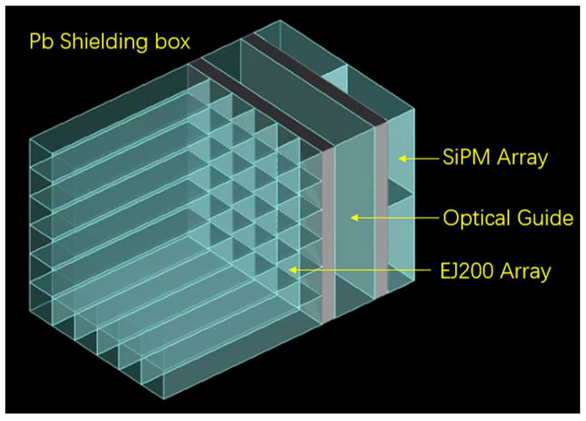
Our fast neutron radiography detector is consisting of an EJ200 array and a SiPMs array. The schematic view of the detector is shown in
Figure 1. Incident fast neutrons collide with hydrogen nuclei in scintillators to produce recoil protons. These protons deposit energy along their trajectory with producing isotropic scintillation photon. Most of the photons are limited in the cuboid scintillator and transferred toward the SiPMs array through the optical guide. The photons are distributed by the optical guide to SiPMs. They are converted to electrical signals and be recorded by the electronics.
The EJ200 organic scintillator has a refractive index of 1.58. The K9 optical glass with 1.5 refractive index is chosen as the optical guide placed between the EJ200 array and the SiPMs array [
19]. It has a low scattering cross section for neutrons. The optical guide can reduce the total internal reflection of scintillating photons at the end face of EJ200. Meanwhile, it can enhance the transverse diffusion of the outgoing scintillating photons to more SiPM pixels, which ultimately improves the detector's detection efficiency and the position resolution for fast neutrons.
3. Detector Simulation and Optimization
Theoretically, the spatial resolution of the pixel-readout type detector is increased with the decrease of the pixel size of scintillator and the SiPMs array [
20]. To determine the influence of main parameters on the imaging quality and to obtain better spatial resolution, the detector structure and detail parameters are optimized by the Monte Carlo simulations using the Geant4 software [
21]. The simulation results are used as a guideline for the detector prototype.
3.1. Spatial Resolution
An important factor in evaluation of an imaging system is the size of the smallest part that can be observed in the tested object, i.e., the spatial resolution of the system. Modulation transfer function is a powerful tool for characterizing the spatial resolution properties of an imaging system and its components.
The evaluation of the position resolution for the imaging systems requires a criterion. The modulation transfer function (MTF) is one of the best ways to represent spatial resolution, by which the digital or graphical representations of resolution can be compared accurately, easily and clearly [
22]. The most commonly deployed technique to measure MTF is the edge method [
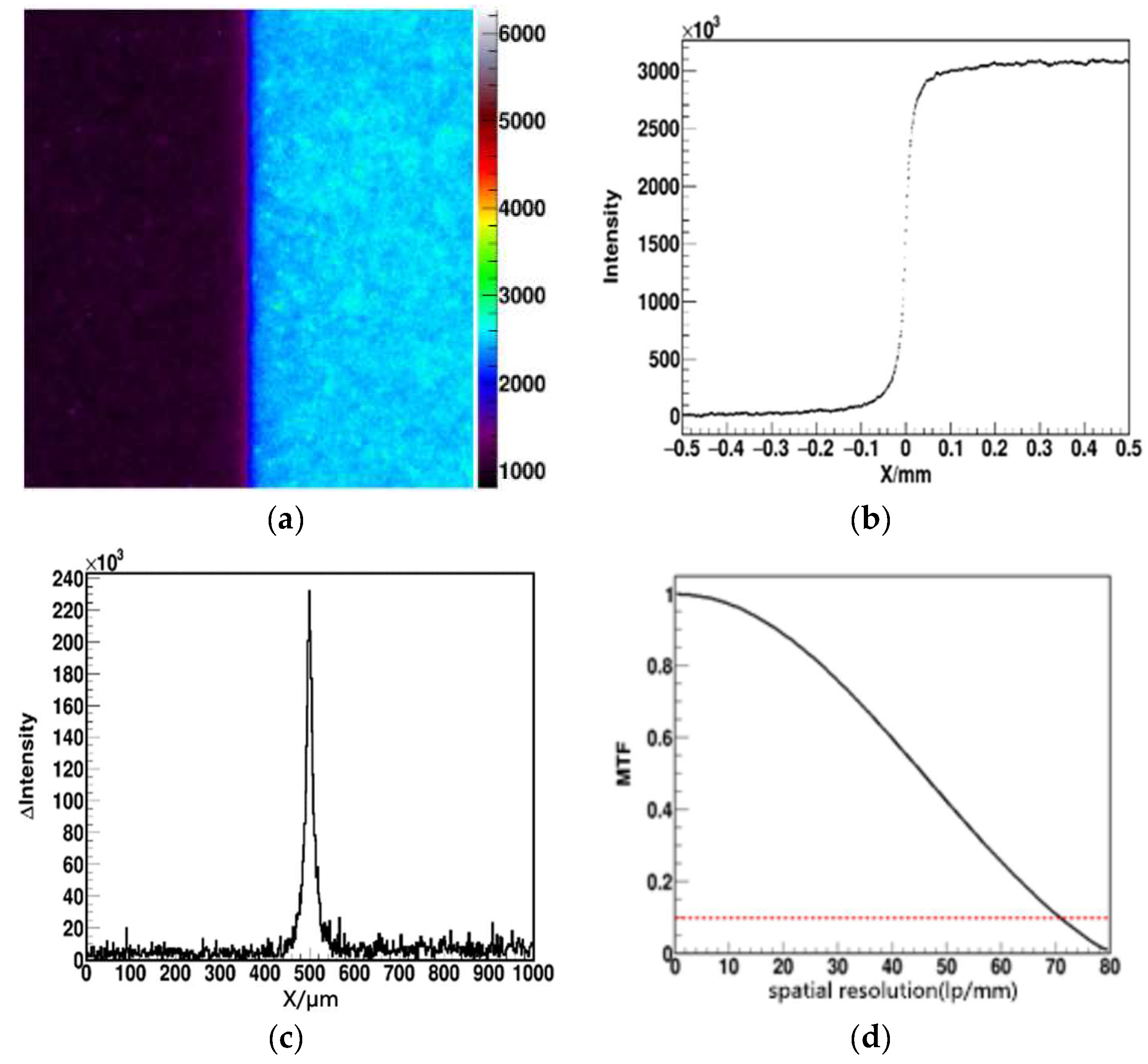
23]. In this method, an object with certain blocking efficiency to fast neutrons, such as boron-containing polyethylene plate, is placed in front of the detector. A neutron source with uniform incidence to the detector is placed in front of the detector. Then the detector can obtain a neutron image with sharp edge, as shown in
Figure 2 (a). The edge-spread function (ESF) is obtained by scanning across the edge image. The projection of neutron count distribution in the X direction is the ESF, as shown in
Figure 2 (b). The corresponding line distribution function (LSF) can be obtained by derivation of the obtained ESF, as shown in
Figure 2 (c). Finally, Fourier transform and normalization are performed on the LSF. The MTF of the detector system is obtained by taking the absolute value of the normalized value, as shown in
Figure 2 (d). For radiation imaging detectors, the spatial frequency at 10% MTF is usually taken as the limit spatial resolution of the imaging system [
24].
For an imaging system with pixel-structure, the basic pixel arrangement and the size influence the quality of the final image. The detector structure is set as
Figure 1 shows. The SiPMs array pixel size is
. This is a common size for the SiPM commercially available in the imaging field. And the thickness of the optical guide is set as 3
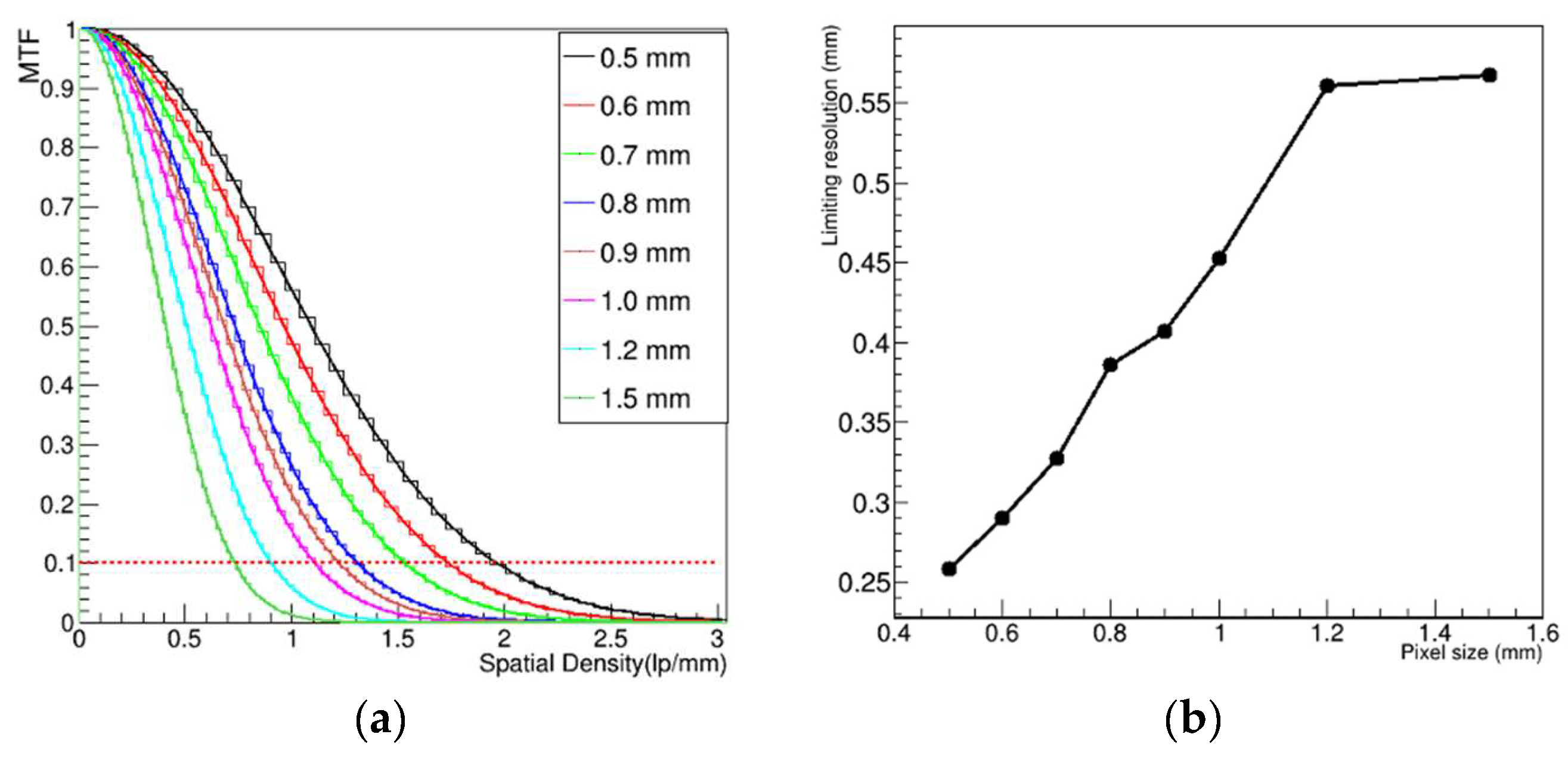
.The pixel size of the cuboid scintillator array is changed in the simulation program. The relationship between the spatial resolution and the pixel size of the scintillator array studied. The simulation results are presented in
Figure 3.
In practice, the spatial resolution for an imaging system can achieve is usually determined according to 10% of the MTF.
Figure 3 (a) shows the
curves when the pixel size of the scintillator array changed from 0.5 to 1.5
. The
Figure 3 (b) shows the position resolution changes when the pixel size of the scintillator array changed. It is clearly that the spatial resolution decreases with the increase of pixel size of the scintillator array. For the pixel size with 0.5×0.5×25
cuboid scintillator array, the limiting spatial resolution is 1.93-line pairs per millimeter
), corresponding to a spatial resolution of 0.26
. For the pixel size with 1.5×1.5×25
cuboid scintillator array, the limiting spatial resolution 0.74
), which corresponds to a spatial resolution of 0.68
. It should be noticed that the 1
pixel size corresponds to a limiting spatial resolution of 0.46
. This is the minimum size of the process that the current research team can achieve.
3.2. Neutron Conversion Efficiency
Ej200 organic scintillator is widely used in fast neutron detect.
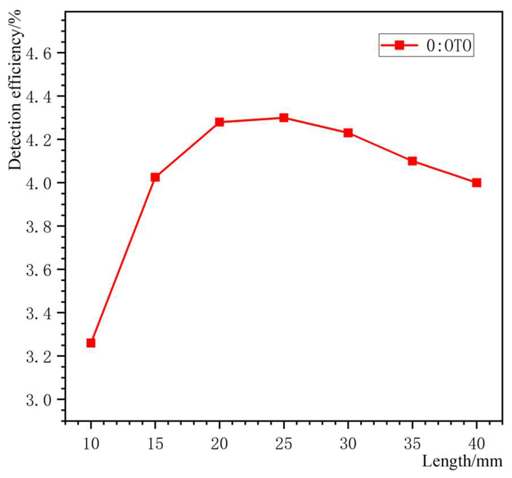
Table 1 shows the technical specifications of the EJ-200. The fast-timing properties make it suitable for large area fast neutron imaging systems. Here, the conversion efficiency ratio is defined as the ratio of the number of neutrons that collide with a hydrogen nucleus to produce a recoil proton to the total number of incident neutrons. The fast neutron conversion efficiency within the scintillator is proportional to the thickness of the scintillator. The EJ200 with cross-section area of
is irradiated by a 14 MeV neutrons source in the simulation program. The variation of neutron detect efficiency with the thickness of the scintillator is recorded.
The energy of the recoil protons produced by the interaction of neutrons with hydrogen nuclei are deposited and caused scintillating photons. When the thickness of the scintillator increases, the amount of recoil protons increases. This is the main reason for the increase in detection efficiency. While the increase in detection efficiency is limited because the scintillating photons number will slash when the thickness of EJ200 exceeds a certain value. See
Figure 4 shows the relationship between neutron detect efficiency and the thickness of EJ200. It is clearly that when the thickness of EJ200 exceeds 25
, the fast neutron detect efficiency start to drop. It is because the scintillating photons at the front of the EJ200 is attenuated or self-absorbed during transmission. The signals of the SiPM cannot trigger the readout electronics effectively.
The scintillator attenuation length given in the manual refers (
Table 1) is the intrinsic light transmission attenuation length. It is determined by only the self-absorption characteristics of the scintillator. The geometric factors of the scintillator are excluded. For a scintillator constrained to a finite size, with the effects related to its geometry such as reflection, refraction and total reflection, as well as with the action of external conditions, the attenuation length for light transmission becomes shorter. The light attenuation length of EJ200 with 1
1
section is also simulated. It is related to its geometry and light shielding craft.
Figure 5 shows the change of the photons number from one side of the cuboid scintillator to other side with the increase of scintillator thickness. This result indicates that the number of photons is decreased when the thickness of EJ200 exceeding 20
. This is garee with the simulation result of the detect efficiency.
So, the thickness of EJ200 should be large enough to maintain the high detection efficiency and small enough to maintain the scintillating photon number to the SiPM readout. A thickness of 25 was chosen for the EJ200.
4. Detector Prototype and Readout Electronics
4.1. SiPMs Array
In this work, J30035 series SiPMs from SensL were selected as the photon sensors [
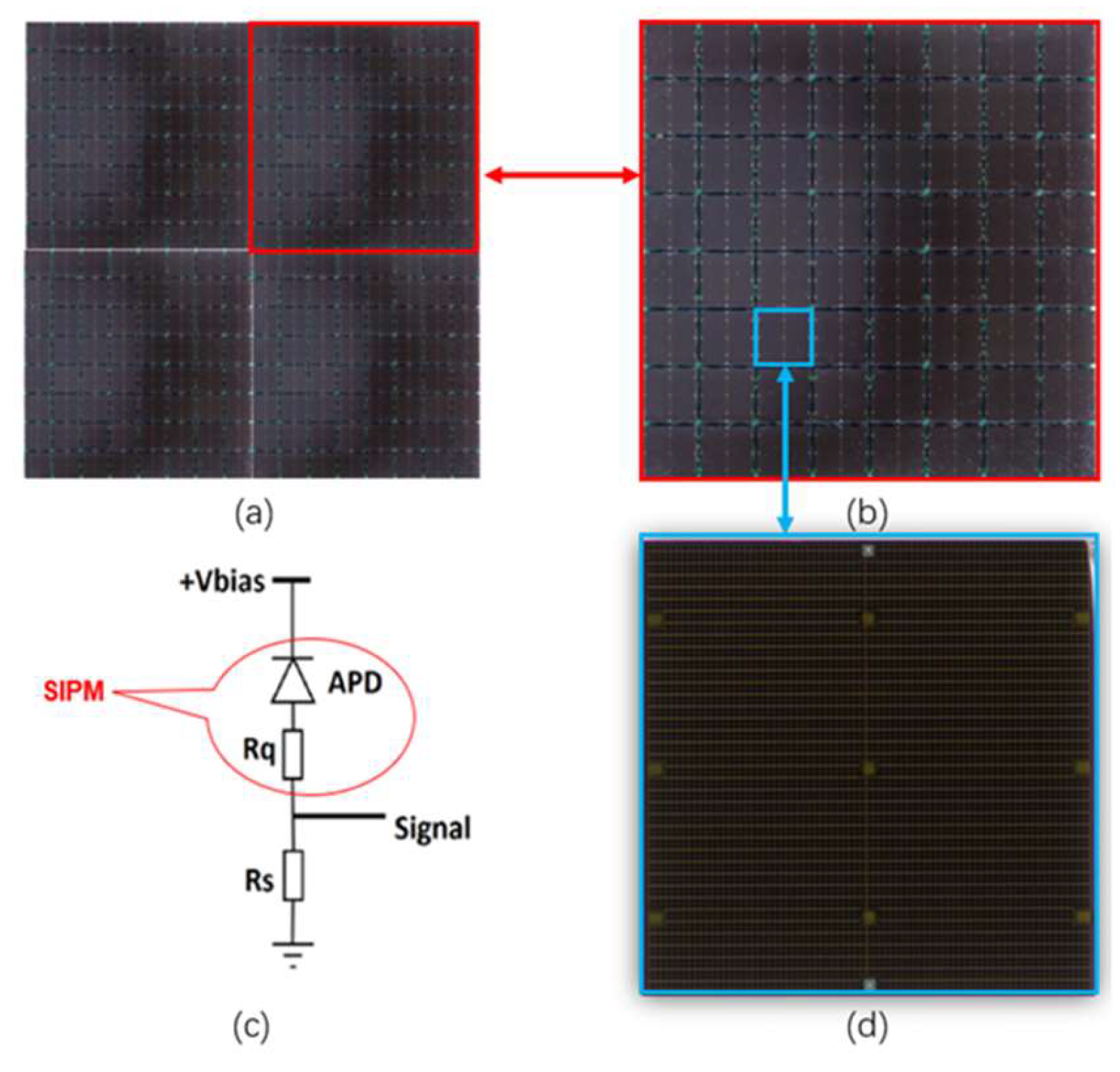
26]. SiPM is a pixel-type photon detector which has many advantages such as compact dimensions, easy integration to arrays, even gain response and low cost. In order to achieve a large area of imaging targets, four 8
8 arrays were arranged to form a complete array with an effective area of about
, as shown in
Figure 7. The size of a single SiPM unit is
, and the gap between adjacent SiPMs is 0.36
Figure 6(a) schematically shows a complete array containing 16
16 arrays. In
Figure 6(b), a schematic diagram of a purchasable array consisting of 8
8 SiPM cells is presented.
Figure 6(d) shows a single SiPM working cell, which includes 4774 microcells with the sizes of 35
.
Figure 6(c) presents a microcell forming a basic SiPM unit. This microcell consists of a photodiode connected in series to a burst resistor operating in the avalanche mode.
4.2. Electronics
The 88 SiPMs array described above provides 64 fast output signals. After encapsulation of the complete array, there will be a total number of 256 SiPMs output. A large number of high-speed electronic channels are needed for the individual readout of SiPM signals.
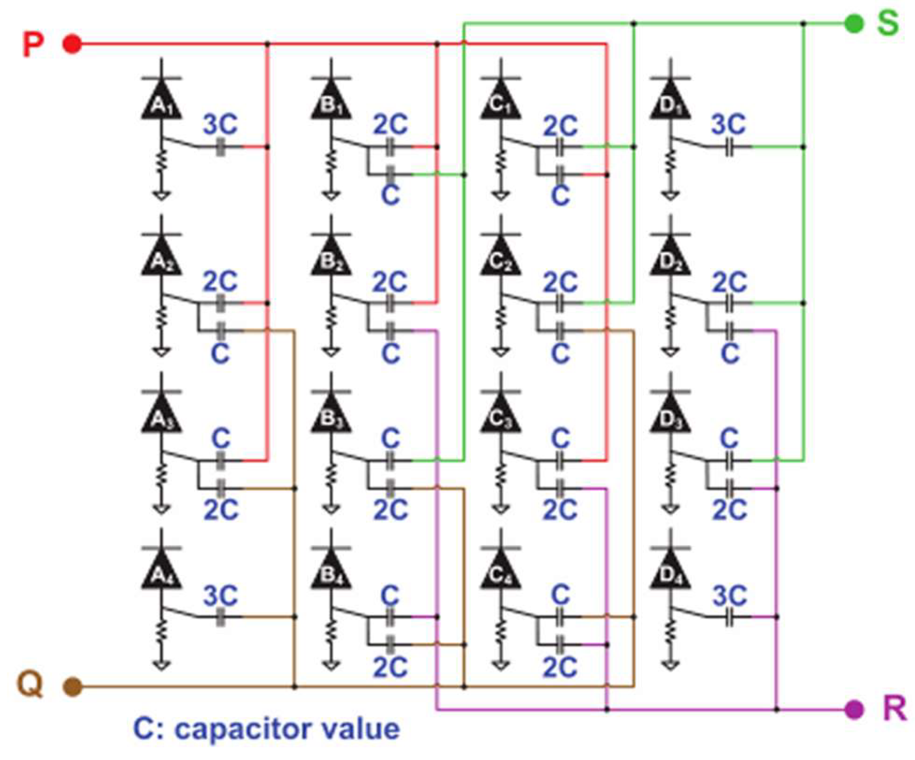
The read-out electronics matched with the SiPMs array adopts capacitive multiplexing network to reduce the readout channel number from 256 (individual readout scheme) to 4 [
27,
28].
The final output four-channel signals are amplified, shaped, and transmitted to the data acquisition system.
Figure 7 shows the schematic diagram of the self-design capacitive multiplexing network. In this network, each anode of the SiPMs is connected to one or more weighted capacitors depending on the position. The anode signal from the SiPMs is split into one or more signals depending on the number of weighted capacitors that are connected to each anode.
The capacitive multiplexed networks encode the 256 SiPMs output signals into 4 position signals (P, Q, R, and S). The energy E of the incident fast neutron and its two-dimensional position (X, Y) are determined by the following equations:
4.3. Scintillator Array and Detector Prototype
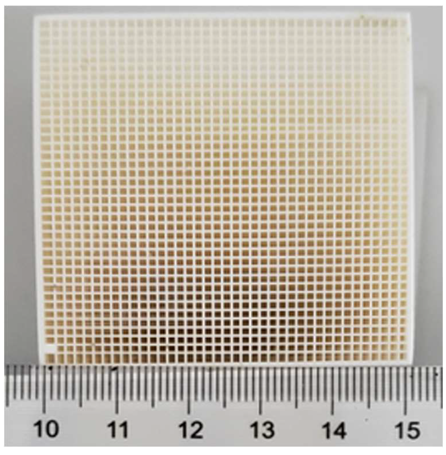
As discussed above, an EJ200 scintillator array with the pixel size of 1
1
20
was cutted and photo isolated to form the fast neutron sensitive scintillator. The scintillator array is shown in
Figure 8. The effective area of the EJ200 array is about 5
5
. A mixture of titanium oxide and glue with the thickness less than 0.2
was applied between adjacent pixels as the photo isolation. The 16
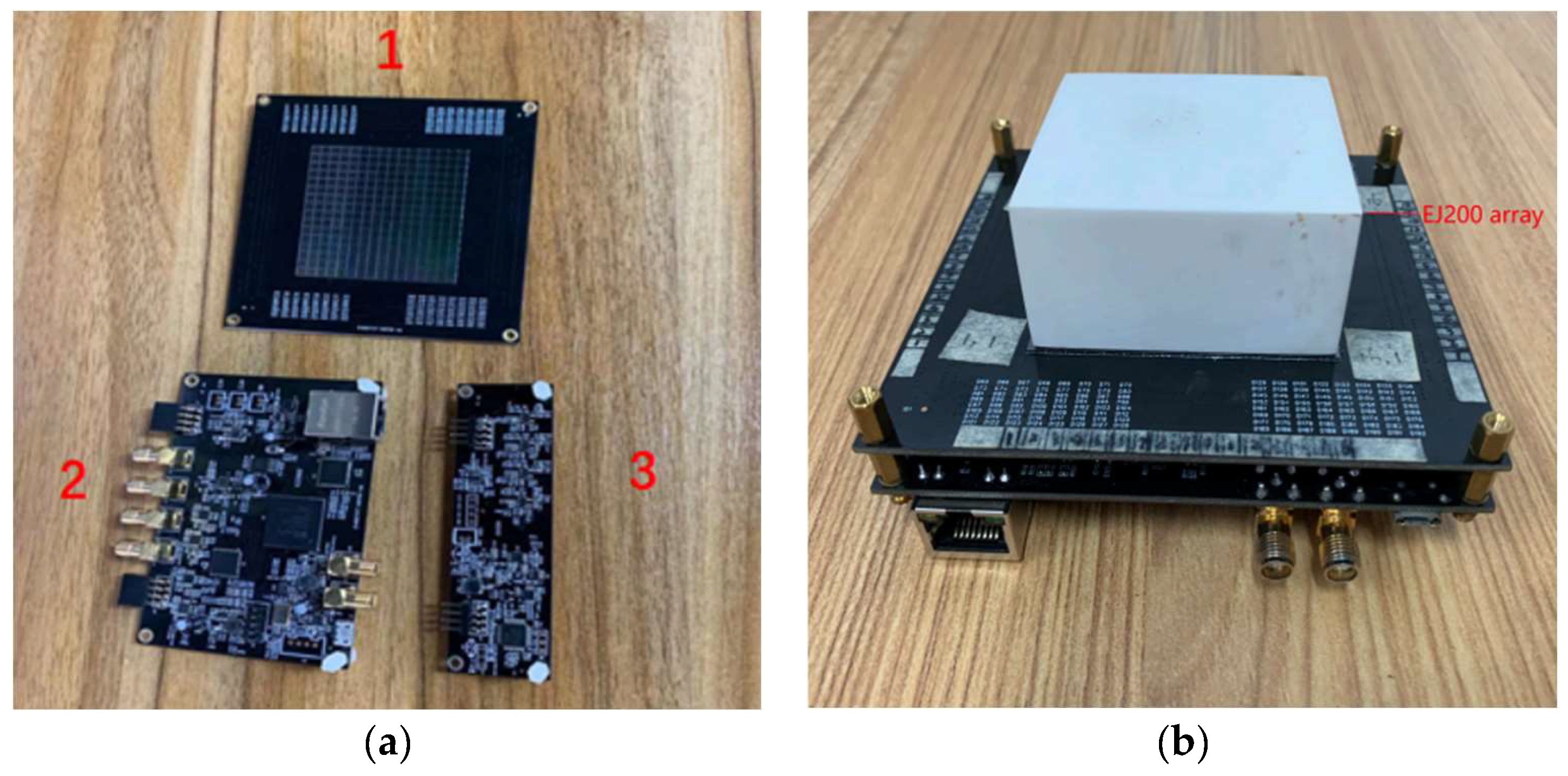
16 SiPMs array and the capacitive multiplexed networks are packaged on the same PCB board, as shown in
Figure 9 (a) part 1.
Figure 9 (a) part 2 is the preamplifier of the 4 position signals (P, Q, R, and S). And
Figure 9 (a) part 3 is the data acquisition module. A gigabit network port is used in the data output module to connect the detector to a personal computer. The acquired data can be accessed online via a computer or transferred to a personal computer for offline processing.
Figure 9 (b) shows the SiPMs array after assembling all the components.
A 3 thickness K9 glass as optical guide is placed between the scintillator array and the SiPMs array to enhance the diffusion of scintillation light and transmit it to the SiPMs array. The silicon oil is used as the coupling medium between the EJ200 array, the optical guide, and the SiPMs array.
The K9 glass has high transparency and high radiation resistance. The 3 thickness is a suitable balance between spreading scintillating light from EJ200 over more SiPM pixels and not decreasing light intensity at each signaled SiPM pixel too much. Moreover, K9 is a good material for fabrication of optical guides due to its low cross-section of neutron scattering.
5. Test of Prototype Performance
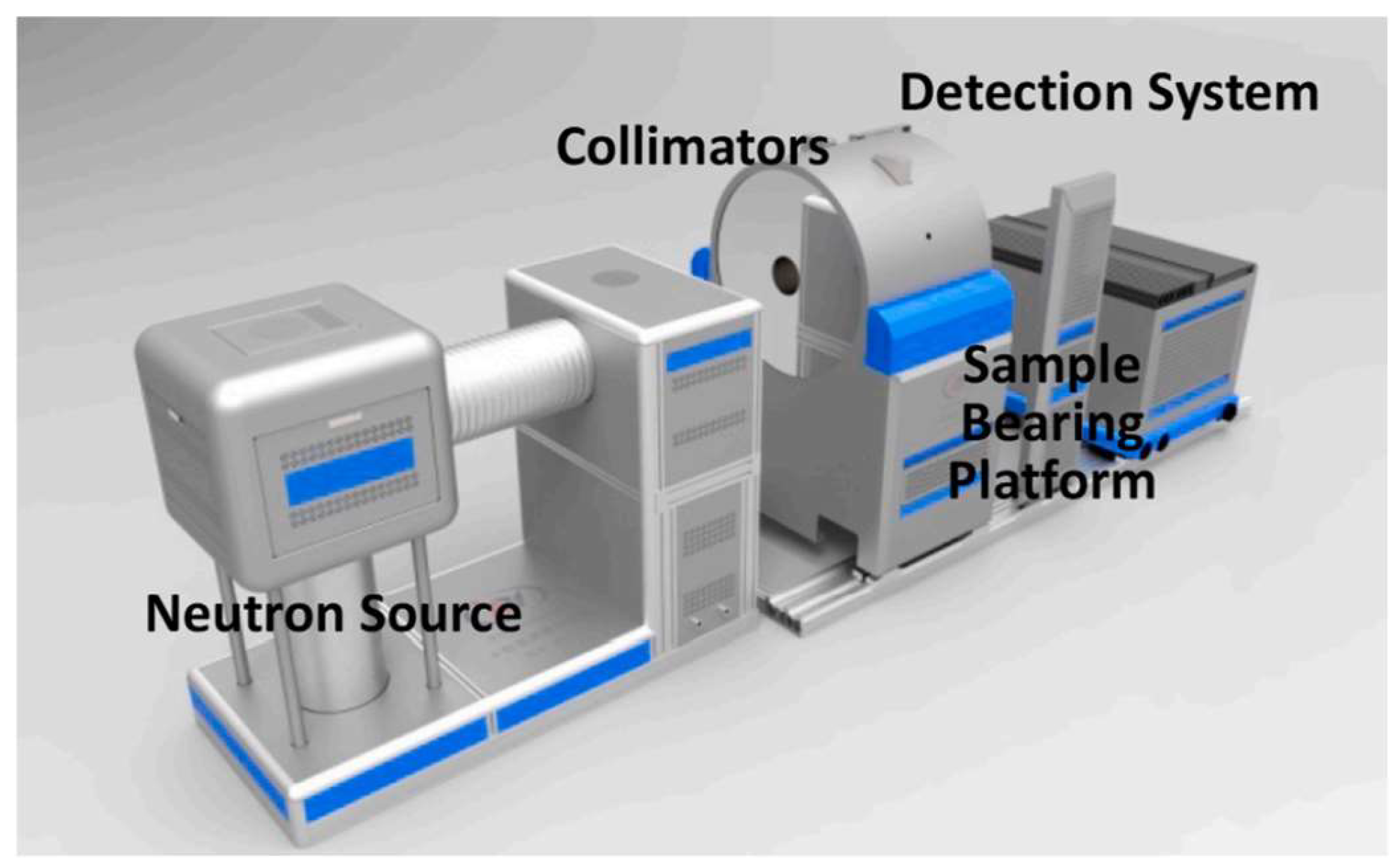
Fast neutron beam experiment was carried out at a 14 MeV D-T neutron generator of the China Academy of Engineering Physics. This is a moveable imaging facility with a compact accelerator D-T neutron source. It consists of a compact accelerator, two different collimators (one for thermal neutrons and the other one for fast neutrons), a sample-bearing platform, and a detection system, which is mounted on the platform for mobility.
Figure 10 shows the sketch map of the facility [
30]. The maximum neutron yield was 1.7×10¹¹ neutrons/s at the deuterium beam current of 1.5 mA.
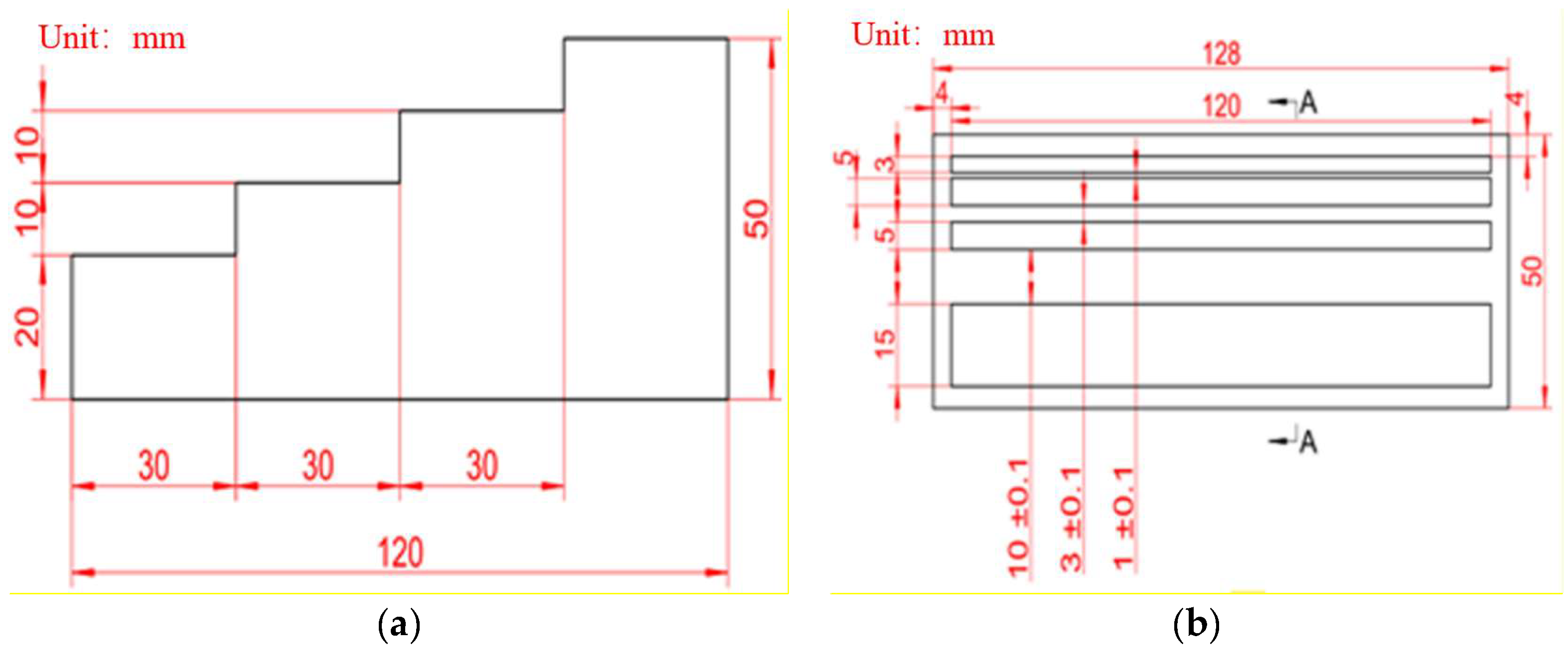
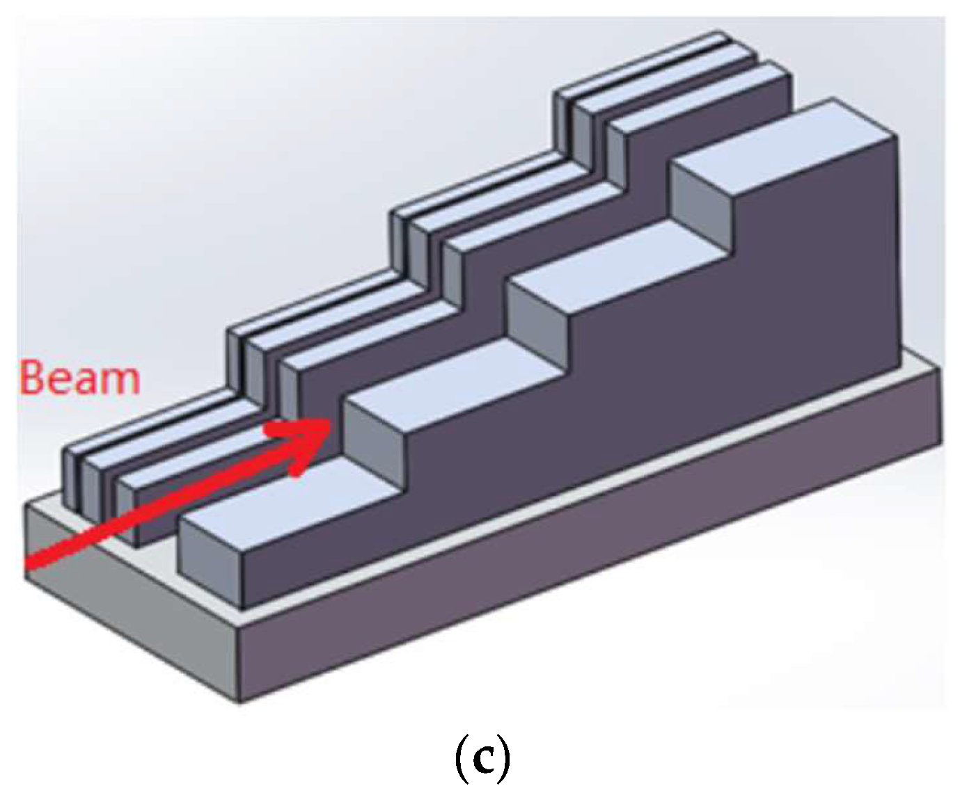
The imaging object used in the experiment is a stainless-steel sample shown in
Figure 11. The sample consists of a 1 cm thick substrate with four stepped pieces with the thicknesses of 3, 5, 5 and 15
. The distance between the outer four steps piece and the edge of the substrate is 4
. The four steps pieces form three slits with the widths of 1, 3 and 10
, respectively. The detector system was shielded by two shield materials: one is lead shield with the thickness of about 5
, other is 3cm thickness boron containing polyethylene in the outer layer. This is designed to shield gamma and stray neutron background. The detector prototype system was powered by a 5V/2A power supply. The SiPMs array was operated at 29.5 V. The acquired data were transferred to a personal computer via an RJ45 interface for the data processing.
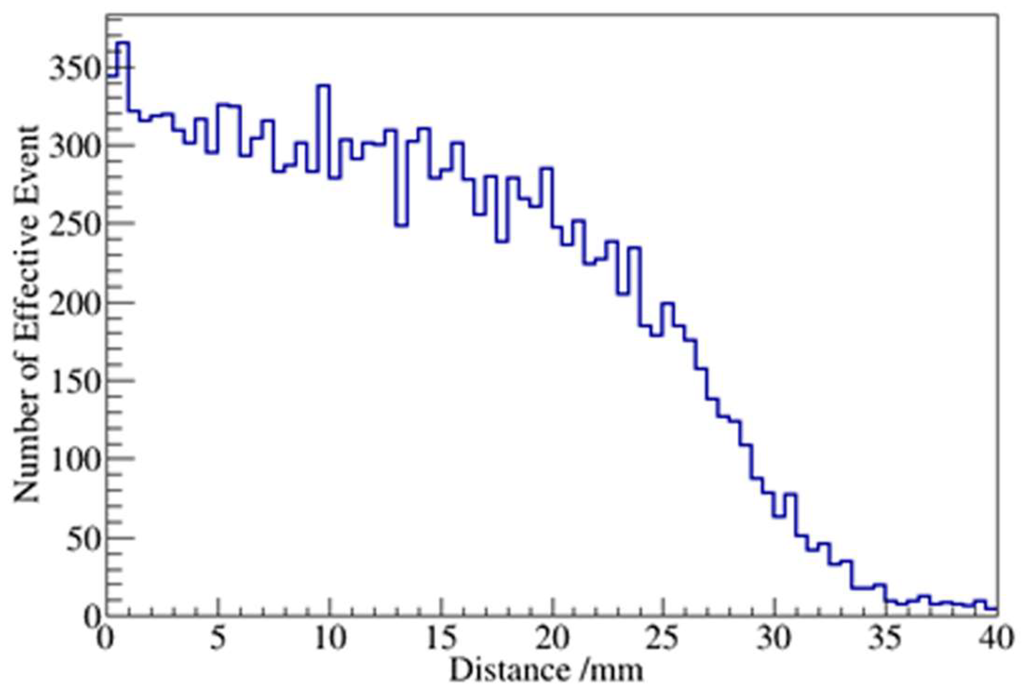
The detector system was placed on the platform with the stainless-steel sample be placed in front of the detector. After 5 minutes irradiation, a 2-dimensional image was obtained, which is shown in
Figure 12. The 4 peaks in
Figure 12 (b) related to different slit spacings of the stainless-steel sample are clearly seen. The second, third and fourth peaks are related to the slits in the sample with the gaps of 1, 3 and 10
, respectively. And three peaks valley are related to three pieces of stainless-steel sample with thickness of 3, 5 and 5
, respectively. The edge of final pieces of stainless-steel sample with 15mm thickness was not observed because the position of the sample was placed too far to the right. The contrast of light and dark in the picture corresponding to different thicknesses of four steps of the steel sample cannot be seen as expected. This may cause by the distortion of the hybrid electronics and the inconsistency of the gain of each SiPM pixel. The position calibration and correction will be carried out to optimized the performance of the detector. The sample image quality could also be improved by normalized by the no sample neutron exposure data. But the no-sample data can’t be used because of the neutron count saturation of the detector system.
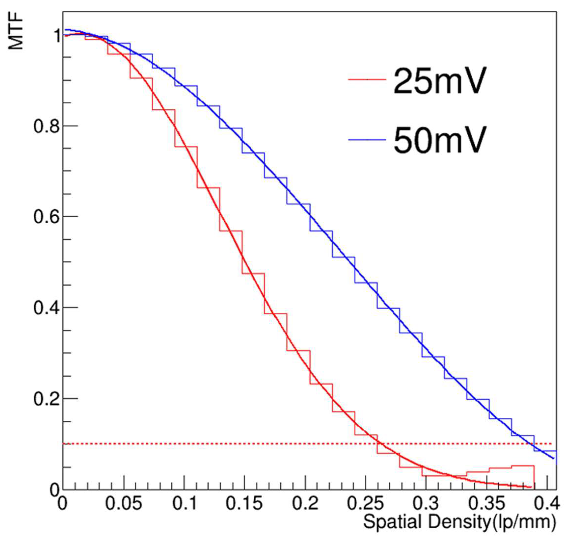
The spatial resolution of the detector is evaluated using the edge diffusion function of the sample, and the modulation transfer function is obtained as shown in
Figure 13. The minimum spatial resolution corresponding to the point where the MTF value equal to 0.1 is 0.27
. The corresponding spatial resolution is 1.852
. When the threshold of the E from equations 4.1 is increased from 25mV to 50 mV, part of the low-energy signals and noise are excluded. And the point (MTF
0.1) corresponds spatial resolution improved to 1.26
.
6. Summary and Discussion
In this paper, an array-type scintillator detector is designed for the fast neutron imaging. Through Monte-Carlo simulations, the main parameters of the detector were optimized. Then a detector prototype composed of 1 ×1 ×25 basic units scintillator array, a 16 × 16 SiPMs array, and a self-design capacitive multiplexing network electronics were designed, fabricated and tested. Using the D-T fast neutron source, the stainless-steel sample imaging was obtained with minimum spatial resolution of 1.26 The radiation damage of the SiPMs was also considered in the experiment. After 24 hours radiation of 14 MeV D-T neutron beam, the gain of the SiPM was measured and compared with the no-radiation one. The gain decreased and the dark current increased apparently. But it can still work normally in the avalanche mode, which means it has certain radiation resistance. The initial research data is not comprehensive enough. Subsequent separate tests will be conducted and corresponding articles will be issued to discuss and explain the irradiation damage issue.
To avoid the long-time irradiation damage of the SiPMs, a new detector with a long bending scintillating fiber array was designed. And the SiPMs array can be placed in the position without direct exposure to the neutron.
SiPMs have an increasingly wide range of applications because of their advantages, which include high photon gain, low operating voltage and relatively low cost. SiPMs can be assembled into photon detection modules of arbitrary sizes. After improving spatial resolution to a sufficient level, these modules can be used for nondestructive detection of larger volume objects than now.
Author Contributions
Conceptualization, B.T., R.C. and Z.S.; Methodology, B.T., X.C., and R.C.; Software, C.H., X.C. and X.W.; Validation, B.T., S.C. and Z.Z.; Formal analysis, Z.Z. and Z.S.; Investigation, X.C. and Q.Y.; Resources, R.C., P.Z., Z.S., Y.W. and Y.L.; Data curation, X.C., Q.Y., C.H., X.C. and D.G.; Writing—original draft, X.C.; Writing—review and editing, X.C. and B.T.; Visualization, C.H. and S.C.; Supervision, H.X. and L.Y.; Project administration, B.T and R.C.; Funding acquisition, B.T. All authors have read and agreed to the published version of the manuscript.
Funding
This research was funded by Guangdong Basic and Applied Basic Research Foundation, China, grant number 2022B1515120071.
Acknowledgments
Thanks for the assistance provided by PhD. Wang Sheng and his team throughout the entire experimental process. And thanks to the China Academy of Engineering Physics for providing the neutron source.
References
- Brzosko J S, Robouch B V, Ingrosso L, Bortolotti A and Nardi V 1992 Nuclear Instruments and Methods in Physics Research Section B: Beam Interactions with Materials and Atoms 72 119. [CrossRef]
- Greenberg R R, Bode P and De Nadai Fernandes E A 2011 Spectrochimica Acta Part B: Atomic Spectroscopy 66 193. [CrossRef]
- Andersson P, Valldor-Blücher J, Andersson Sundén E, Sjöstrand H and Jacobsson-Svärd S 2014 Nuclear Instruments and Methods in Physics Research Section A: Accelerators, Spectrometers, Detectors and Associated Equipment 756 82. [CrossRef]
- Li H, Zou Y B, Wang S, Wen W W, Liu S G, Tang G Y, Lu Y R and Guo Z Y 2013 Physics Procedia 43 66.
- Zboray R, Adams R and Kis Z 2018 Applied Radiation and Isotopes 140 215. [CrossRef]
- Ambrosi R M, Fraser G W, Feller B, Street R, Watterson J I.W, White P and Downing G 2003 Nuclear Instruments and Methods in Physics Research Section A: Accelerators, Spectrometers, Detectors and Associated Equipment 500 351. [CrossRef]
- Ambrosi R M, Fraser G W, Street R A, Watterson J I.W, Lanza R C, Dowson J, Abbey A F, Feller B, Downing G, White P and Stevenson T 2005 Nuclear Instruments and Methods in Physics Research Section A: Accelerators, Spectrometers, Detectors and Associated Equipment 542 271. [CrossRef]
- Dangendorf V, Laczko G, Reginatto M, Vartsky D, Goldberg M, Mor I, Breskin A and Chechik R 2005 Nuclear Instruments and Methods in Physics Research Section A: Accelerators, Spectrometers, Detectors and Associated Equipment 542 197. [CrossRef]
- Cortesi M, Zboray R, Adams R, Dangendorf V and Prasser H M 2012 Journal of Instrumentatio 2012 7 C02056. [CrossRef]
- Mikerov V, Samosyuk V and Verushkin S 2005 Nuclear Instruments and Methods in Physics Research Section A: Accelerators, Spectrometers, Detectors and Associated Equipment 542 192. [CrossRef]
- Zhang F Q, Qi J M, Zhang J H, Li L B, Chen D Y, Xie H W, Yang J L and Chen J C 2014 Acta Physica Sinica 63 128701. 2014.
- Ma Z W, Li W M, Ran J L, Huang Z W, Zhang S J, Li K J and Yao Z E 2018 Journal of Instrumentation 13 P05034. [CrossRef]
- Liu L, Lu M H, Cao W Q, Peng L K and Chen A 2016 Medical Imaging 2016: Physics of Medical Imaging 9783 283. [CrossRef]
- Cha B K, Bae J H, Lee C H, Jeon H, Kim H, Chang S, Kang B S and Cho G 2009 Nuclear Instruments and Methods in Physics Research Section A: Accelerators, Spectrometers, Detectors and Associated Equipment 607 145. [CrossRef]
- BIRKS J B 1964 The Theory and Practice of Scintillation Counting, pp. 15-38.
- ELJEN Technology. https://eljentechnology.com/.
- Grodzicka-Kobylka M, Szczesniak T and Moszyski M 2017 Nuclear Instruments and Methods in Physics Research Section A: Accelerators, Spectrometers, Detectors and Associated Equipment 856 53. [CrossRef]
- Huang T C, Fu Q B, Lin S P and Wang B 2017 Nuclear Instruments and Methods in Physics Research Section A: Accelerators, Spectrometers, Detectors and Associated Equipment 851 118. [CrossRef]
- Light Guide for Crystals and photodetectors (epic-crystal.
- Zhao B Q, Huang Y and Wang C L 2023 Atomic Energy Science and Technology 57 9.
- Agostinelli S, Allison J, Amako K, et al. 2003 Nuclear instruments and methods in physics research section A: Accelerators, Spectrometers, Detectors and Associated Equipment 506 250. [CrossRef]
- Boreman G D 2001 Russ.chem.
- Cao R L and Biegalski S R 2007 Nuclear Instruments & Methods in Physics Research Section A-accelerators Spectrometers Detectors and Associated Equipment 582 621. [CrossRef]
- Wang Y, Han S B, He L F, Wei G H, He L J, Wu M M, Wang H L and Liu W T 2012 Nuclear Technology 35 275.
- Maxwell, C. EJ-200 Plastic Scintillator Data Sheet, Eljen Technology, Sweetwater. 2010. [Google Scholar]
- SensL. https://www.onsemi.com/.
- Zhang X H, Qi Y J and Zhao C L 2012 Chin Phys C 36 973. [CrossRef]
- Park H, Yi M, Lee J S 2022 Biomedical Engineering Letters 12 263. [CrossRef]
- Choe H J, Choi Y, Hu W, Yan J H and Jung J H 2017 Physics in Medicine and Biology 62 120. [CrossRef]
- Wang S, Yin W, Liu B, Li H, Sun Y, Cao C, Wu Y, Huo H Y, Zhu S L, Lou B C, Wu C L and Tang B 2021 Applied Radiation and Isotopes 169 109564. [CrossRef]
|
Disclaimer/Publisher’s Note: The statements, opinions and data contained in all publications are solely those of the individual author(s) and contributor(s) and not of MDPI and/or the editor(s). MDPI and/or the editor(s) disclaim responsibility for any injury to people or property resulting from any ideas, methods, instructions or products referred to in the content. |
© 2024 by the authors. Licensee MDPI, Basel, Switzerland. This article is an open access article distributed under the terms and conditions of the Creative Commons Attribution (CC BY) license (https://creativecommons.org/licenses/by/4.0/).
