Introduction
Issues of amplifier stability have been widely studied within the framework of the general theory of stability of circuits containing active elements [
1,
2]. However, amplifier stability is a much more serious problem in the microwave range than at low frequencies. This is especially true when using semiconductor active elements, when, with an increase in the absolute frequency range in which the stability of the amplifier must be ensured, the influence of parasitic parameters associated with the finite dimensions of the leads and housing elements of such active elements simultaneously increases [
3]. In this case, a powerful microwave amplifier easily loses stability when the bias voltage exceeds a certain value and can go into the mode of generating both deterministic and chaotic oscillations [
4].
Unusual phenomena associated with changes in stability are also observed in a number of cases in multimode active systems [
5,
6], as well as when they are exposed to complex, for example, biharmonic signals, [
7,
8] both with frequencies that differ greatly in frequency and and close in frequency. When interacting with the eigenmodes of the system, the output signal at certain parameter values becomes chaotic.
It is known that at a high input signal level, the amplification stages of transistor microwave devices operate in a significantly nonlinear region of modes. Under these conditions, the properties of the p-n junction depend on the level of the input signal, and the output signals depend nonlinearly on the input influences. Violation of the linearity of the amplifier in the case of several input signals leads, as the experimental results presented in this work show, in addition to the known distortions, to chaotic oscillations at the output.
The purpose of this work is to study the conditions for the occurrence of the phenomenon of chaotization of oscillations at the output of powerful microwave amplifiers based on bipolar transistors.
1. Materials and Methods
The work experimentally investigated the complex operating modes of high-power amplifiers in the centimeter wavelength range, which arise when amplifying a biharmonic signal with comparable amplitudes of its components. The amplification stages were single-stage microwave amplifiers which included: one active element—a bipolar microwave transistor and matching circuits based on microstrip lines. Amplifier stages based on bipolar transistors such as 2T982 A-2, 2T937 B-2, 2T938 A-2 were used. Microstrip lines and matching circuits were created using standard technology on a material with a high dielectric constant, FLAN-10.
Two single-frequency signals from G4-80 standard signal generators, each amplified to the required power level by its own TWT, were used as input. The biharmonic signal was fed directly to the input of the amplifier stage through a microstrip ring adder, the summing inputs of which were connected to the TWT outputs. To achieve decoupling, their outputs were connected to the inputs of the microstrip adder through coaxial ferrite valves. The spectrum of the output signal of the amplifier stage was observed on a spectrum analyzer С4-60.
As a result of the research, two distinct phenomena were established. The first occurs under conditions when the interval between the frequencies of the biharmonic signal F1 and F2 is small compared to the gain band of the transistor stage П, i.e., when the relation is satisfied. The second phenomenon occurs under conditions when the frequencies of the biharmonic signal F1 and F2 are located at the boundaries of the gain band of the transistor stage, so that. This separation is determined not only by the frequency distribution of the input biharmonic signal, but also by the conditions of chaotization of oscillations imposed on the parameters of the input signal and supply voltages and, apparently, the determining mechanisms of the transition to chaos.
2. Amplification of a Biharmonic Signal with Similar Frequencies
When the frequency difference of the biharmonic signal is much less than the gain band of the transistor stage, two effects are observed:
- the output signal of the amplifier contains combinational components both in the gain band (with a frequency interval ) and outside this band at frequencies , where , etc.;
- at a certain difference in the frequencies of the acting biharmonic signal, the output oscillations in the amplification band become chaotic.
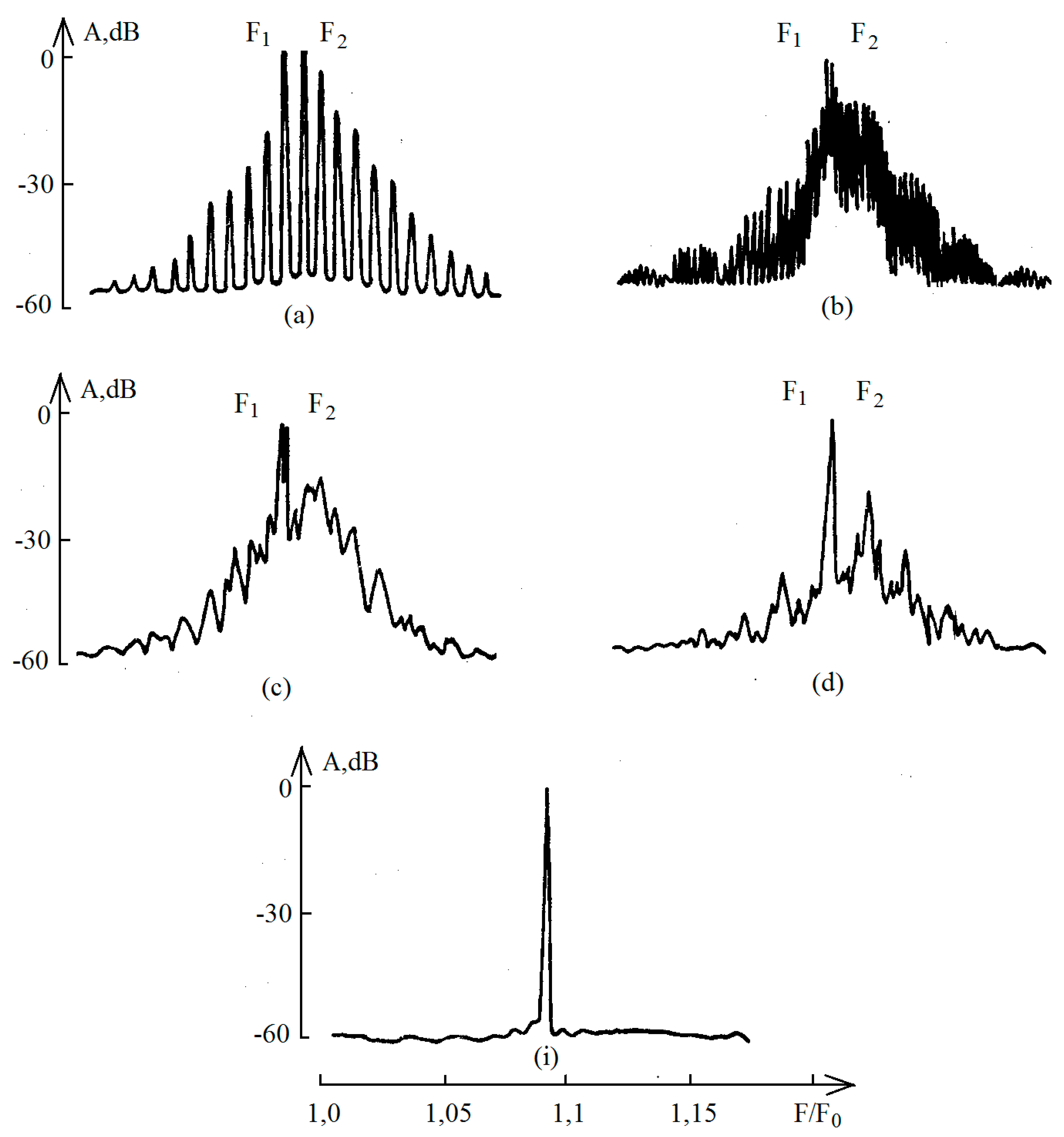
The evolution of the output signal of the amplifier stage based on the 2T937 B-2 transistor with a sequential decrease in the frequency difference of the external biharmonic signal within the range 0 <
< 18 MHz is shown in
Figure 1 (a - i). The amplification stage
was studied at the following supply voltages: Voltage between the emitter and the base of the transistor U
eb = - 0.4 V, voltage between the collector and the base of the transistor U
kb = 15 V. Input signal power, where P
1 and P
2 are the powers of single-frequency components at frequencies F
1 and F
2 accordingly, P
nom is the rated output power of a single-frequency signal at which the signal power at the amplifier output is maximum.
The spectra of oscillations at the output demonstrate the presence of combination components of the difference between the frequencies F
1 and F
2 at
>18 MHz. In this case, the spectrum is equidistant with an interval between frequencies
(
Figure 1, a). This is accompanied by the appearance of modulation components with frequencies
, where
.... A decrease
leads to the appearance of a noise pedestal in the gain band (
Figure 1, b,
= 6 MHz) and global chaotization of oscillations (
Figure 1, c) at
= 3 MHz. The envelope of the noise signal basically follows the frequency response of the amplifier stage. Chaotization of oscillations in the gain band does not lead to chaotization of oscillations at frequencies
,
.... The spectrogram in this part of the range remains equidistant with a decrease in the amplitude of oscillations with increasing
. A further decrease
leads to a weakening of the amplitude of chaotic oscillations (
Figure 1, d) and the usual single-frequency amplification with equal frequencies of the input biharmonic signal (
Figure 1, i).
Experiments show that chaotization of oscillations in a powerful microwave amplification stage on a transistor is possible only at certain voltage values between the emitter and base of the transistor Ueb < - 0.38 V. For other types of amplification stages, chaotization of oscillations was observed at the following bias voltages: for transistors of type 2T938 A -2 at Ueb < - 0.58 V, for transistors of type 2T982 A - 2 at Ueb < - 0.25 V; Moreover, the transition to chaos in the amplifier stages on these transistors is similar to that considered.
The excitation of chaotic oscillations also depends on the power of the input signal. The most developed chaos was observed at power values for all types of amplifier stages. In this case, the power of chaotic oscillations Pch, measured using a narrow-band filter that blocks the signal at the frequencies of the external biharmonic signal, was . A decrease in the power of the biharmonic signal led to a decrease in the power of chaotic oscillations, and then to their complete breakdown. But at the same time, chaotization is still possible at large absolute value bias voltages Ueb. When the input signal power is more than that , a narrowing of the spectrum of chaotic oscillations is observed with a further transition to a multi-frequency operating mode.
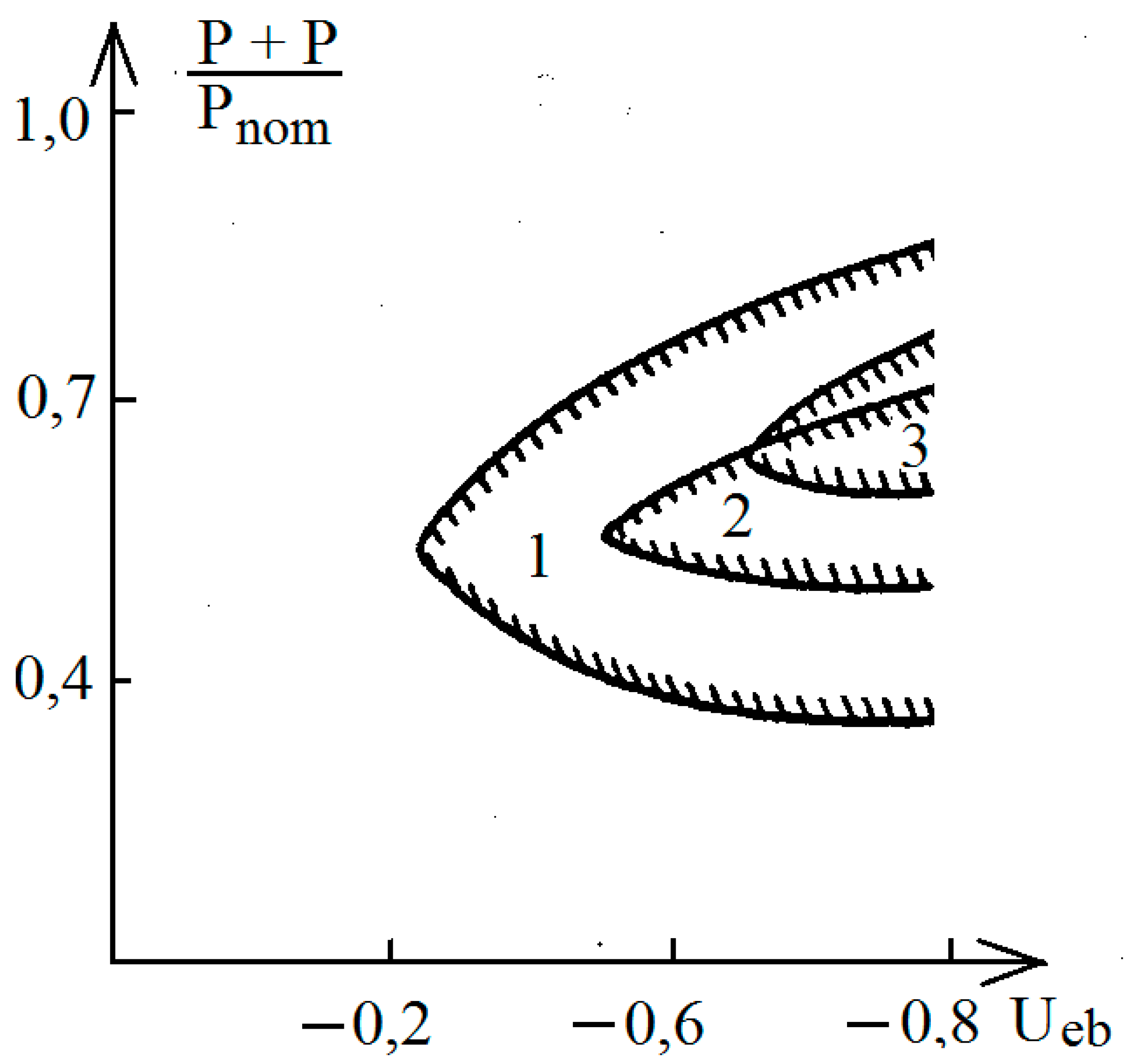
A diagram of the zones of existence of chaotic oscillations at
, corresponding to their highest power for the types of amplifier stages under study, depending on the power of the input biharmonic signal
and the bias voltage U
eb is presented in
Figure 2. In this figure, numbers 1 - 3 indicate the zones of existence of chaotic oscillations for various types of amplifier stages on transistors 2T982 A-2, 2T937 B-2 and 2T938 A-2, respectively.
The presence of zones of chaotic oscillations allows us to make an assumption about the mechanism of occurrence of such oscillations in powerful amplifier stages on bipolar transistors with an input biharmonic signal with similar frequencies. This mechanism is based on the well-known fact that microwave generation occurs when the control voltage reaches a value corresponding to the threshold, which for bipolar transistors is within - 0.8 V. In this case, when the frequencies of the external biharmonic signal approach each other and the number of combinational components increases (due to nonlinear amplification ) the signal at the output of the amplifier stage takes on the character of beats, in which relatively short intervals with large instantaneous values and time intervals during which the instantaneous values of the signal are periodically alternating. The presence of periodic significant surges in the signal causes, if the constant bias is sufficiently large (ensuring the opening of the transistor), a loss of stability and the occurrence of generation. However, such generation exists only for a limited time, determined by the duration of intervals with large instantaneous values of the total signal at the input of the transistor. In this case, a sequence of oscillation trains with arbitrary duration and initial phase is formed.
At time intervals corresponding to small values of the total signal at the transistor input, generation is interrupted and occurs again at the next time interval with large instantaneous values of the total signal at the transistor input. In this case, bursts of generation at successive time intervals occur in the frequency range corresponding to the maximum gain. In addition, these generation trains turn out to be unsynchronized with each other, since the system manages to “forget” the phase during the time between successive generation bursts. This circumstance determines the chaotic nature of the generated oscillations, which manifests itself in the formation of a continuous spectrum in the signal amplification band.
The frequency interval between the components of the input biharmonic signal, at which the most powerful chaotic oscillations were observed, is different for the types of amplifier stages studied. The value of the interval between frequencies corresponding to these modes was 7,0, 3,0 and 2,0 MHz for amplifier stages on transistors 2T982 A-2, 2T937 B-2 and 2T938 B-2, respectively.
3. Amplification of a Biharmonic Signal with Frequencies at the Edge of the Gain Band
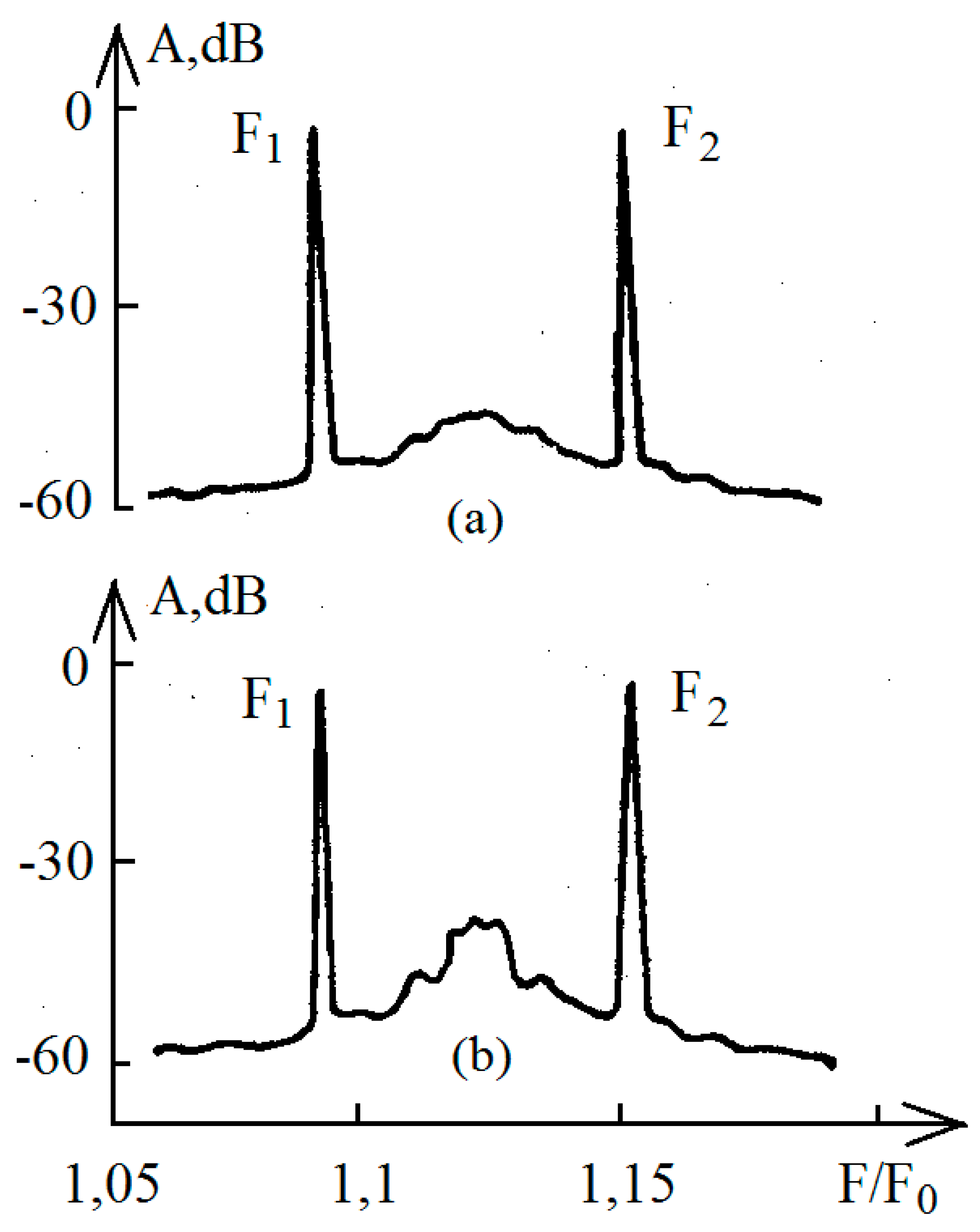
Typical spectrograms when a biharmonic signal is amplified at the band boundaries are shown in
Figure 3. Spectrograms were obtained by amplifying a tandem biharmonic signal with amplification stages based on a 2T937 B-2 transistor at various bias voltages Ueb. Spectrogram in
Figure 3, a corresponds to the value U
eb = - 0.3 V, spectrogram in
Figure 3, b was obtained at a voltage U
eb = - 0.6 V. The voltage on the collector in both cases is U
kb = 15 V. As can be seen from the spectrograms shown, a noise pedestal was observed in the gain band of the cascade, which existed within a wide range of transistor supply voltages and input powers external biharmonic signal. The maximum noise pedestal corresponded to the maximum frequency gain of the cascade. The amplitude of the noise pedestal with a constant input signal depends to the greatest extent on the transistor bias U
eb, which determines the transistor gain and the degree of nonlinearity of the emitter p-n junction. Amplifier stages based on transistors 2T982 A-2 and 2T938 A-2 demonstrated similar behavior. Reducing the bias voltage to zero did not lead to the complete disappearance of the noise pedestal, which indicates that the chaotization mechanism in this case is different from that described earlier.
Changing the power and frequency ratio of the influencing signal also affects the amplitude of the noise pedestal. Each type of amplifier stage has its own input signal power level (), at which the amplitude of the noise pedestal is maximum, while relatively it was approximately the same and corresponded to the level . In this case, the power of the noise pedestal, measured by a wideband bandpass filter, corresponded to the level .
Varying the frequencies of the input signal both in the direction of increasing the interval and in the direction of decreasing it with a constant input power led to a smooth decrease in the amplitude of the noise pedestal. The maximum amplitude of the noise pedestal corresponded to the frequency range of the biharmonic signal that meets the condition = П.
Thus, the nature of the phenomenon observed in these experiments differs from the previously described case. The experiments carried out allow us to assume that the main role in the mechanism of occurrence of the noise pedestal in this case is played by the nonlinear capacitance of the emitter p-n junction, which, together with the input matching circuits of the amplifier stage, forms a nonlinear circuit with a natural frequency at which the self-excitation conditions are not met. The input biharmonic signal, acting on the nonlinear circuit, leads to a periodic change in its natural frequency. At some sufficiently large amplitude of influence, the oscillations in the circuit become chaotic. In this case, the circuit is in a pre-excited state, which in the spectral representation is considered as a noise pedestal.
The presented mechanism of chaotization of oscillations in powerful amplifier stages on bipolar transistors when amplifying a biharmonic signal with frequencies at the boundaries of the amplification band is apparently similar to the chaotization mechanism considered in [
7,
8].
Conclusions
The work investigated the complex modes of three types of amplifier stages of the centimeter wavelength range based on bipolar transistors 2T982 A-2, 2T937 B-2 and 2T938 A-2 under the influence of a powerful biharmonic signal with biharmonic components comparable in power. Two characteristic phenomena have been established that demonstrate different mechanisms for the occurrence of chaotic oscillations in powerful amplifier stages based on bipolar transistors.
The first case, which meets the condition << П, is characterized by the presence of combinational components preceding the chaotization of oscillations as the interval between the frequencies of the biharmonic signal decreases . The mechanism of chaos in this case is based on the generation of trains of microwave oscillations with an arbitrary initial phase, and the frequency of the generated oscillations is generally uncorrelated with the frequencies of the input biharmonic signal. The power of chaotic oscillations in this case is comparable to the power of the input signal with single-frequency amplification.
In the second case, when the frequencies of the external biharmonic signal lie at the boundaries of the gain band, = П, the chaos oscillations manifests itself in the spectral representation in the form of a noise pedestal in the gain band of the transistor cascade; moreover, the power of this noise pedestal is an order of magnitude less than the power of the output signal. The main role in this case is probably played by the nonlinear capacitance of the emitter p-n junction, the nonlinear dependence of which, with an input tandem biharmonic signal, leads to chaotic modulation of the system’s own mode.
The experiments carried out with three types of amplification stages show that the observed phenomena of chaotization of oscillations at their output are, with a high degree of generality, universal for high-power amplification stages on bipolar microwave transistors.
In some cases, these phenomena can explain abnormally high noise levels in the output stages of powerful microwave amplifiers based on bipolar transistors when amplifying complex signals.
Financing the Work
The work was carried out within the framework of the state tusk.
Conflict of Interest
The authors have no conflict of interest.
References
- J. Henrie, A.J. Christianson, W.J. Chappell. Linear–Nonlinear Interaction and Passive Intermodulation Distortion. // IEEE Transactions on Microwave Theory and Techniques. 2010. V. 58. № 5. P. 1230 – 1237. [CrossRef]
- A.S. Kotov, P.M. Meleshkevich, A.D. Zakurdaev, M.S. Vostrov, A.V. Polyakov, A.V. Khromov, S.M. Zakharov, V.P. Motorin, V.M. Polyakova, E.M. Shipilo, E.A. Grishina, E.T. Kharabadze, N.I. Levashov. Condition and prospects for the development of small-sized onboard solid-state vacuum microwave integrated products // Electronic equipment, Ser. 1, Microwave technology. 2013. № 3. V. 526. P. 90–110.
- D.E. Root, J. Verspecht, J. Horn, M. Marcu. X-Parameters, characterization, modeling, and design of nonlinear RF and microwave components (Cambridge University Press, The Cambridge RF and Microwave Engineering Series, 2013).
- S. V. Savel’ev, L. A. Morozova. A bipolar transistor-based high-power chaotic oscillator with selected Inertia.// Journal Technical Physics. 2020. V. 65. No. 12. P. 2056–2060. [CrossRef]
- N.V. Stankevich, O.V. Astakhov, A.P. Kuznetsov, E.P. Seleznev. Excitation of chaotic and quasi-periodic oscillations in a multi-circuit generator with a general control circuit // Letters to JTF. 2018. V. 44, № 10. P. 46-53.
- E.P. Seleznev, N.V. Stankevich. Complex dynamics of a non-autonomous oscillator with a controlled phase of external influence // Letters to JTF. 2019. V 45. № 2. P. 59-62.
- V.A. Buts, D.M. Vavriv. Interaction of high-frequency and low frequency oscillations: threats and benefits // In: International Kharkov symposium on physics and engineering of microwave, millimeter and submillimeter waves (Kharkov, MSMW, 2013).
- A.Y. Nimets. D.M. Vavriv. Bistability in the doffing oscillator under combined high and low frequency forcing // Issues of atomic science and technology. 2015. V. 98. № 4. P. 282-285.
|
Disclaimer/Publisher’s Note: The statements, opinions and data contained in all publications are solely those of the individual author(s) and contributor(s) and not of MDPI and/or the editor(s). MDPI and/or the editor(s) disclaim responsibility for any injury to people or property resulting from any ideas, methods, instructions or products referred to in the content. |
© 2024 by the authors. Licensee MDPI, Basel, Switzerland. This article is an open access article distributed under the terms and conditions of the Creative Commons Attribution (CC BY) license (http://creativecommons.org/licenses/by/4.0/).


