1. Introduction
The integration of automation and intelligent material handling systems has significantly accelerated the evolution of manufacturing processes. Among the most pivotalelements in modern production environments are Automated Guided Vehicles (AGVs), which have become indispensable in facilitating flexible and efficient transport of materials. This paper simulates AGVs in a toy car manufacturing scenario.
The simulation environment used for this paper is GPenSIM, an advanced toolbox developed for the MATLAB platform to model, simulate, and analyze discrete systems. GPenSIM provides a robust platform for simulating complex interactions and workflows characteristic of industrial processes.
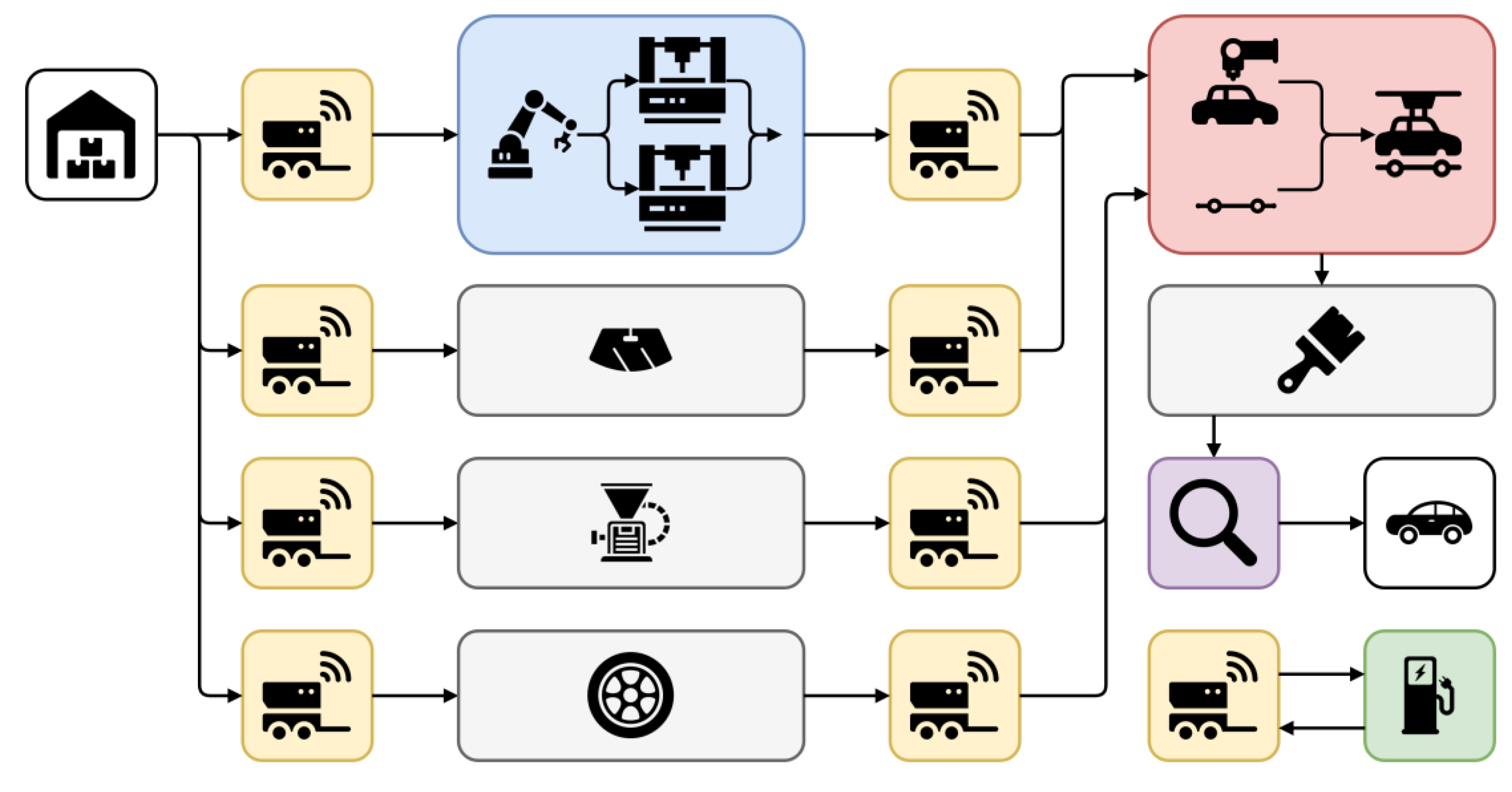
The production line simulated comprises a series of interconnected stations as shown in
Figure 1: a warehouse for raw material storage, a CNC machine for crafting the car’s top half, a plastic molding station for the bottom part, a machine dedicated to tire manufacturing, another for creating the plastic windows, and an assembly machine that combines all the car components. Subsequent to assembly, the cars undergo painting and are then subjected to a quality control check to ensure that the final product meets the established standards.
AGVs, the backbone of our production line, are employed as the primary means of transportation between these stations, forming an integral part of the production line.
AGVs that run out of battery charge get charged by one of 5 chargers. The objective of the simulation is to evaluate and compare the efficiency of the production line with a varying number of AGVs. In this paper:
Section 1 presents a compact literature study.
Section 2 presents formal definitions of Petri Nets and introduces GPenSIM.
Section 3 presents the overall methodology for modeling a toy car production line as a Modular Petri Net model. The results of the analysis of the Modular Petri Net model, with the focus on AGV battery parameters, is presented in
Section 4. Finally,
Section 5 presents some limitations of this work.
2. Relevant Works
Several studies have explored the simulation of AGVs and other systems using Petrinets and related methodologies. [
1] presents an agent-based Petri net model for AGV management in manufacturing system. This work is interesting and useful as it adds some intelligence to the Petri Net model. [
2] focuses on the traffic control of AGVs in a large manufacturing system, using Petri Net models. A more macroscopic work on motion control of AGVs is presented in [
3]. [
4] proposed an intelligent detection method of bottleneck (IDMOB) in discrete manufacturing systems, employing object-oriented colored Petri nets (OOCPN) combined with cloud simulation. This approach abstracts production cells as Petri net sub-modules and uses cloud simulation to emulate real processing, demonstrating its effectiveness in a case study from the power transformer industry.
Most of the works on AGVs using Petri Nets focus on path planning. [
5] addressed the path planning problem of multi-type robot systems in industrial areas using timed colored Petri nets. Their work focused on dividing tasks into various types and developing a planning approach for different types of mobile robots, including AGVs, to efficiently complete tasks within specified time windows. This study highlights the potential of Petri nets in optimizing the path planning and scheduling of AGVs in production environments. [
6] and [
7] propose approaches using new concepts known as “related Places” and “Undirected Petri Nets”, respectively.
However, the focus of our paper is completely different from the existing literature. In this paper, by varying the battery charge reduction rate, we explore how different energy consumption models affect the overall productivity and efficiency of AGVs. This aspect is crucial in understanding the real-world implications of battery technology advancements on AGV operations. Furthermore, this paper paves an approach for the investigation into the optimal number of charging stations, which is a significant logistical challenge in AGV deployment.
3. Petri Nets and GPenSIM
This paper uses Petri Nets to model the AGVs. More specifically, Modular Petri Nets.
3.1. Petri Nets
A Petri net is composed of two elements: Places and Transitions. A transition represents an event or an action done by an object; the event can be anything from mixing smoothies, combining two elements, disassembling, and charging. A place represents a state or position in a system. For example, if a machine is available or how far a car has traveled on the road. An arc connects places and transitions; since Petri Nets is a bipartite graph, an arc cannot connect the same type of elements (e.g., a place to another place). A token represents an object that goes from one place to another through the firing of a transition.
3.1.1. Petri Nets: Definition
Petri Net (P/T Petri Net) is a four-tuple [
8], [
9]:
where,
P: set of places, P = {p1, p2, . . . , pnp }.
-
T: set of transitions, T = {t1, t2, . . . , tnt }.
P ∩ T = ∅.
F: set of directed arcs; F ⊆ (P × T) ∪ (T × P). The default arc weight W of fij ( fij ∈ F, an arc going from pi to tj or from ti to pj) is singleton, unless stated otherwise.
M: row vector of markings (tokens) on the set of places. M = [M(p1), M(p2), . . . , M(pnp )] ∈ Nnp , M0 is the initial marking.
3.2. Modular Petri Nets
A modular Petri net is a Petri net that consists of one or more Petri Modules and zero or more Inter Modular Connectors (IMCs). A Petri Module is like any other Petri Net, but with some specific rules:
Tokens can only enter a Petri Module through its Input Ports that are transitions.
Tokens can only exit a Petri Module through its Output Ports, which are also transitions.
Local places and transitions of a Petri Module can not have any direct arcs with elements outside the Petri Module. Modular Petri Nets possess two important benefits over the non-modular Petri Nets [
10]: Modular Petri Nets allow independent development and testing of Petri Modules. After thorough testing of individual Petri Modules, they are connected by IMCs to form the overall model. Petri Modules can run on different computers. Hence, they run faster (take less simulation time).
3.2.1. Modular Petri Nets: Definition
Modular Petri Net (MPN) = Petri Modules + IMCs (Inter-Modular Connectors).
An MPN consists of one more Petri module and zero or more IMCs.
Formal Definition of MPN:
An MPN is defined as a two-tuple:
Formal Definition of Petri Module:
A
Petri Module is defined as a six-tuple:
where,
TIPΦ ⊆ T: TIPΦ (Input Ports)
TLΦ ⊆ T: TLΦ (local transitions)
-
TOPΦ ⊆ T: TOPΦ (Output Ports)
TIPΦ, TLΦ, and TOPΦ, all are mutually exclusive:
TIPΦ ∩ TLΦ = TLΦ ∩ TOPΦ = TOPΦ ∩ TIPΦ = ∅.
TΦ = TIPΦ ∪ TLΦ ∪ TOPΦ (the transitions of the module).
PLΦ ⊆ P the local places. Since a module has only local places, PΦ ≡ PLΦ.
-
∀p ∈ PLΦ,
- -
p∈(TΦ∪ ∅). (a local place can be input by transition inside the module or none)
- -
p• ∈ (TΦ ∪ ∅). (an output of a local place can be transition inside the module or none)
-
∀t ∈ TLΦ,
- -
•t ∈ (PLΦ ∪ ∅). (input place of a module transition is a local place or none)
- -
t• ∈ (PLΦ ∪ ∅). (output place of a module transition is a local place or none)
-
∀t ∈ TIPΦ
- -
•t ∈ (PLΦ ∪ PIM ∪ ∅). (input places of Input Ports can be local places or places in IMCs or none)
- -
t• ∈ (PLΦ ∪ ∅). (output places of Output Ports can be local places or places in IMCs or none)
-
∀t ∈ TOPΦ
- -
•t ∈ (PLΦ ∪ ∅). (input places of Output Ports can be local places or an empty set)
- -
t• ∈ (PLΦ ∪ PIM ∪ ∅). (output places of Output Ports can be local places, IM-places, or none)
AΦ ⊆ (PL × TΦ) ∪ (TΦ × PL): where aij ∈ AΦ (internal arcs)
MΦ0 = [M(pL)] (initial markings in local places)
Formal Definition of Inter-Modular Connector:
An Inter-modular Connector (IMC) is defined as a four-tuple:
Ψ = (PΨ, TΨ, AΨ, MΨ0)
where,
PΨ ⊆ P: PΨ is the set of places in the IMC (known as the IM-places). ∀p ∈ PΨ,
- -
•p ∈ (TOP ∪ TΨ ∪ ∅). (input transitions of IM places can be Output Ports of modules, IM transitions of this specific IMC, or none)
- -
p• ∈ (TIP ∪ TΨ ∪ ∅). (output transitions of IM places can be Input Ports of modules, IM transitions of this specific IMC, or none) (IM places are not allowed to have direct connections with local transitions of modules)
∀p ∈ PΨ, ∀i p ∈/ PΦi (a local place of a module can not be an IM-place).
TΨ ⊆ T: TΨ is the transitions of the IMC (aka IM-transitions). ∀t ∈ TΦ,
- -
•t ∈ (PΨ ∪ ∅). (input places of IM-transitions can be IM-places of this specific IMC or none)
- -
t• ∈ (PΨ ∪ ∅). (output places of IM-transitions can be IM-places of this specific IMC or none)
∀t ∈ TΨ, ∀i t ∈/ TΦi (an IM-transition is not allowed to be a member of any modules).
AΨ ⊆ (PΨ × (TΨ ∪ TIP)) ∪ ((TΨ ∪ TOP) × PΨ): where aij ∈ AΨ is the IMC arc.
MΨ0 = [M(pΨ)] initial markings in IM-places.
3.3. GPenSIM
This paper uses GPenSIM for the implementation and simulation of the Petri Net model. GPenSIM allows model logic to be imposed on transitions via the pre-processor and post-processor files [
11]. Also, GPenSIM supports the use of resources, providing a compact Petri Net model for systems with a large number of resources. A resource represents something that is needed for a machine to work; for example, a robot arm can be a resource.
GPenSIM is a MATLAB toolbox developed by the third author of this paper [
11]; GPenSIM is freely available [
12]. GPenSIM’s coloring facility is useful for developing Petri Net models of real-life discrete systems [
13]. Also, GPenSIM allows modeling large discrete systems with Modular Petri Nets [
10].
4. Methodology
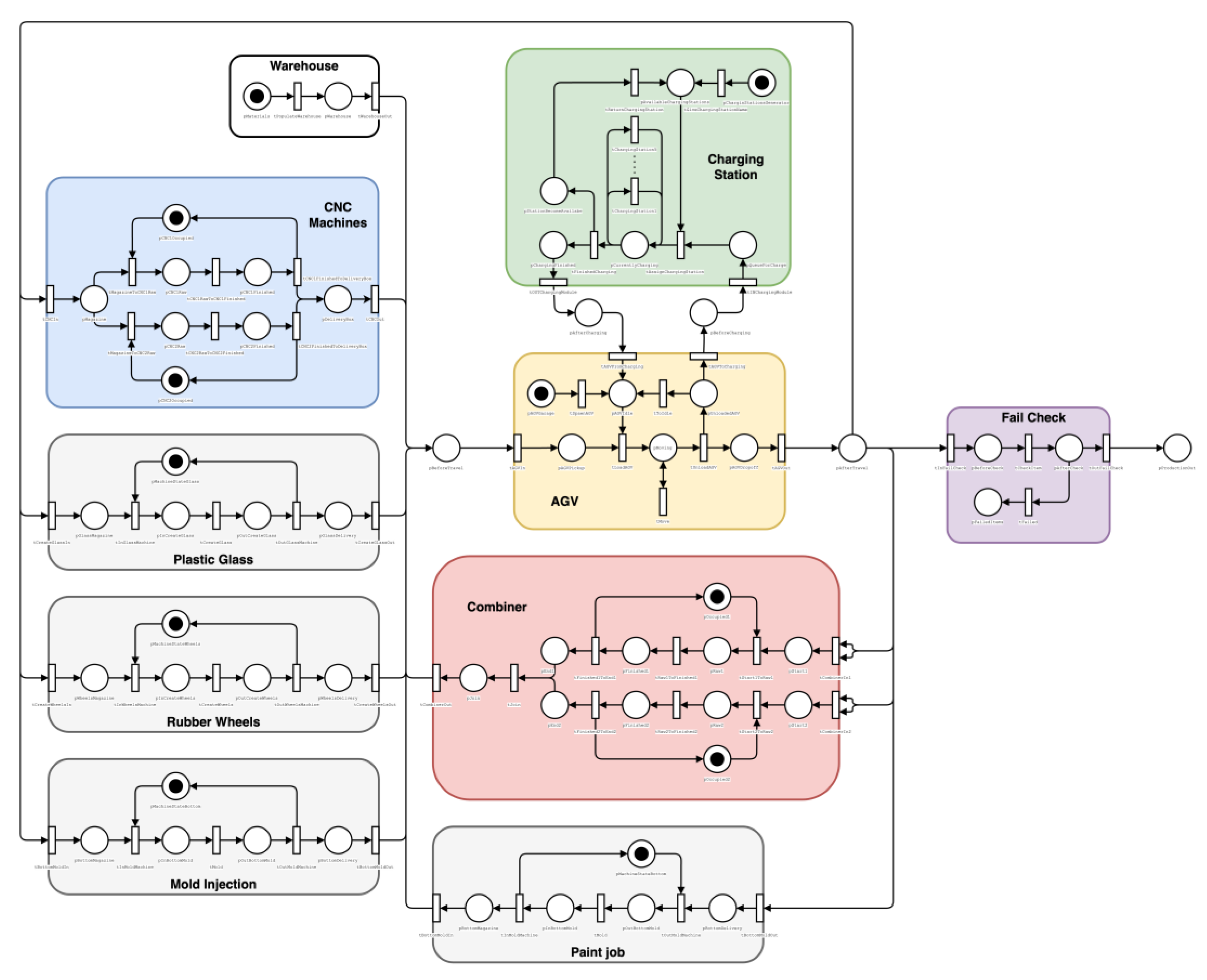
The toy car production line creates each part, combines them, and paints them before the product goes through a fail-check to see if it functions properly and is safe for the public. Each of these processes is represented by a Petri Module in the Modular Petri Net (see
Figure 2). For each token (representing material or product) to be able to move around the factory, we use AGVs. In the simulation, the movement of an AGV from point A to point B is also done in a separate Petri Module, as well as the charging of the AGVs. Hence, each process in the real-world scenario is represented by a Petri Module, following the rules.
4.1. Modular Approach
Dividing the whole Petri Net into Petri Modules has several advantages over a non-modular approach: It allows us to implement each Petri Module individually with only minor adjustments needed to combine them into one large network later. It also makes the network more readable since different responsibilities are clearly divided. In the following sections, we will describe the Petri Modules in more detail, starting with the “Warehouse,” proceeding to the subsequent Modules in the production line, and ending with the “Fail Check.”
4.1.1. Warehouse
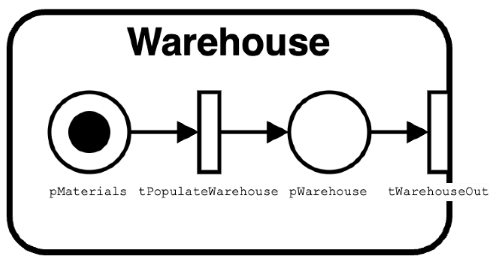
“Warehouse” is the simplest Petri Module; see
Figure 3. This module is responsible to feed a specified amount of materials into the network, which is achieved by first initializing pMaterials with 100 tokens. These tokens are then given colors by the tPopulateWarehouse transition. The transition will circle through a list of material names and assign them to the tokens. This assures that the materials in pWarehouse are distributed evenly. In the context of the complete Petri Net shown in
Figure 2, the importance of tWarehouseOut becomes apparent. This transition’s responsibility is to assign each token a destination based on its material. The AGV Petri Module will later use this destination color to calculate the distance it has to travel with the token.
4.1.2. Automated Guided Vehicle
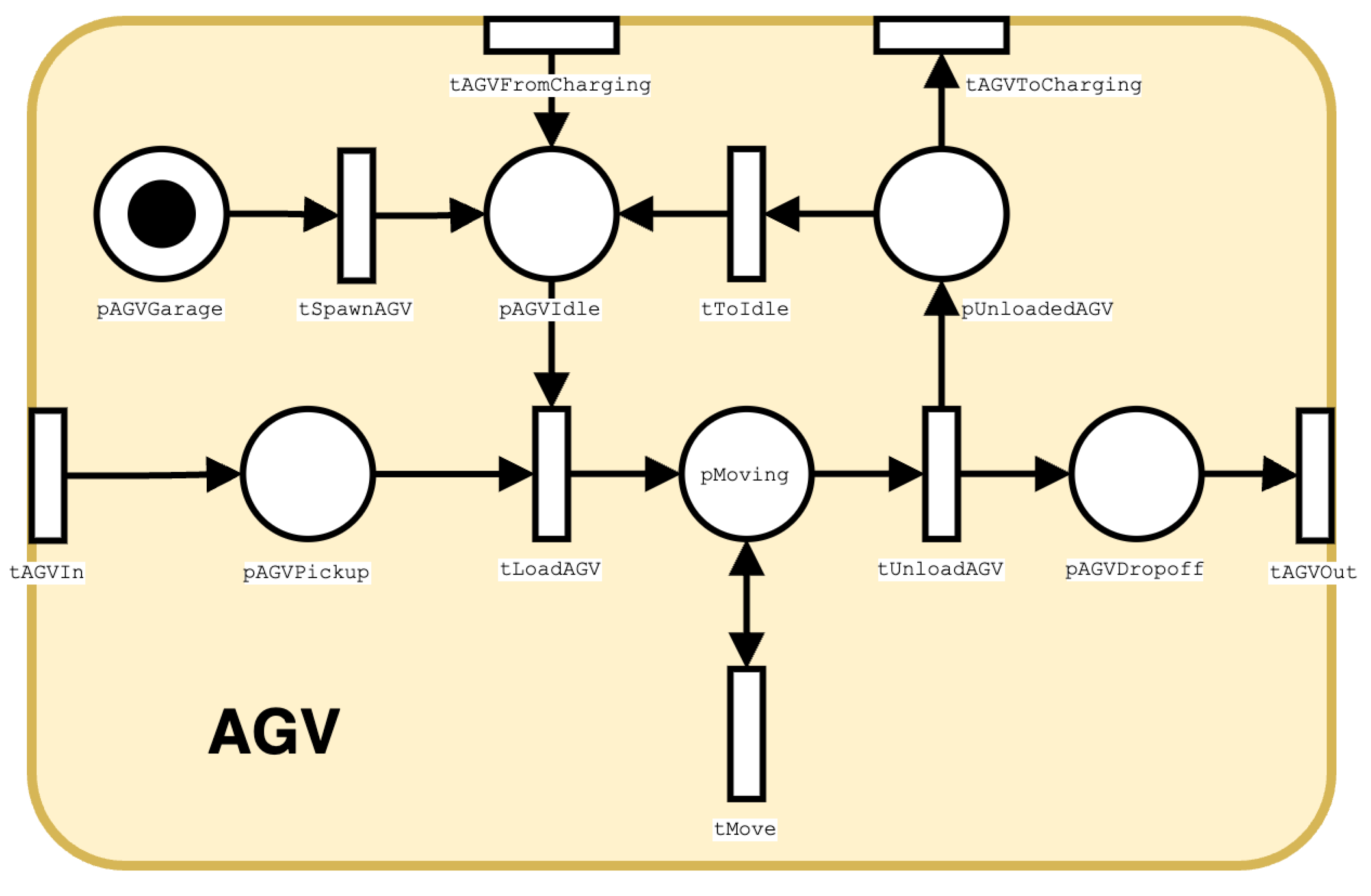
The AGV Petri Module plays a central role. This module is shown in
Figure 4. When a token arrives in the pAFVPickup place, it will have the following attributes assigned as colors: type, location, destination. Based on this information, the tLoadAGV will calculate the distance the AGV will have to travel to transport the material to its destination. tLoadAGV will also assign one AGV token to the material. This is done so there is only a set number of AGVs traveling with materials between the simulated machines. The AGV tokens are initiated in the pAGVGarage place. In the transition tSpawnAGV they are assigned a name, a value for the AGVs speed and a battery charge of 100%. The AGV tokens will stay in pAGVIdle until they are needed to transport a material.
The place pMoving holds a number of tokens which can be anywhere from 0 to the number of AGVs. They each have a color representing the AGVs traveled distance and its battery charge. These values are continuously updated by the tMove transition.
Should an AGV run out of battery it will no longer be able to move. Once an AGVs traveled distance is greater than the range it has to transport the material, the token will be taken out of pMoving by the transition tUnloadAGV. This transaction fires into two places: pAGVDropoff to represent the unloaded material and pUnloadedAGV to represent the empty AGV. The port tAGVOut has the important task to strip the token of all colors that are associated with an AGV. It also removes the location at which the material started.
This leaves a token with the following attributes embedded in its colors: material type, destination. Based on this information the different modules, representing the machines in the production line, can later choose a token representing the correct material needed for their production sub-process.
The transitions tToIdle and tAGVToCharging check if the tokens color, representing the AGVs battery charge is greater or less than 20%. Should it be less than 20%, the token will be sent to the Charging Station module. If there is sufficient charge left in the AGV, it will be sent to pAGVIdle to wait for another travel. AGVs returning from the Charging 231 station will also en up in pAGVIdle. The observant reader will notice that this simulation 232 omits the fact that an AGV will have to travel empty from the machine it dropped of its material to the place where it will pick up the next material.
4.2. Charging Station
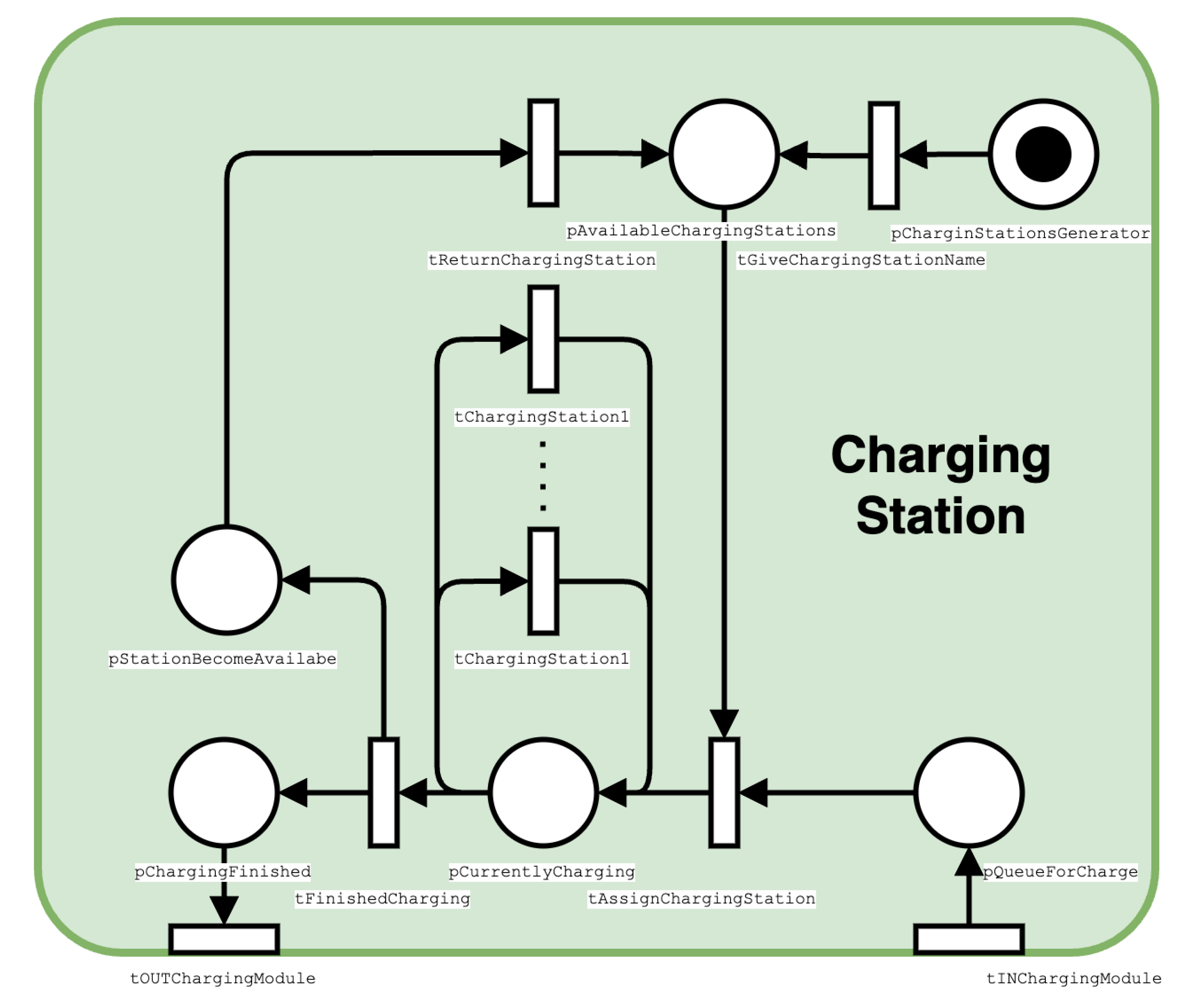
The charging station is the Petri Module representing a set of charging stations that will charge the AGV’s as they get low battery; see
Figure 5. The transition tINChargingModule will work as the input port. tINChargingModule will only accept tokens with battery status 20% or below from pBeforeCharging. When a AGV gets into pQueueForCharge, it will either be assigned a charging station through adding of color in tAssignChargingStation, or it will await when a token gets available in pAvailableChargingStations. The charging stations gets the color they need by having uncolored tokens from pChargingSationGenerator242 go through the tGiveChargingStationName, where it will give the name ‘ChargingStationX’ 243 where ‘X’ is the number one through the amount of charging stations in the module, which in our simulation is 5. The transition tAssignChargingStation will take a token from pQueueForCharge and a token from pAvailableChargingStation, where it will combine the color that is information about the AGV (name and battery) and the charging station color. When a AGV got a charging station, it will be placed in pCurrentlyCharging. It will then go through tChargingStationX, which will only accept tokens which have the ’ChargingStationX’ color, this way only one AGV can use a charging station at a time.
Every time the token goes through tChargingStationX, it will take the colors, add 20 (20%) to the battery color, and then put the colors back in the same order. When the color that represents the battery in the token reaches 100, it can not go any further up. When this happens, tFinishedCharging will take the token and place a it in both pStationBecomeAvailable and pChargingFinished. The output tOutPutChargingModule will take a token from pChargingFinished and only keep everything except for the ‘ChargingStationX’ color. tReturnChargingStation does the exact opposite, it will take tokens from pStationBecomeAvailable and only take the ‘ChargingStationX’ color and put it in pAvailableChargingStations, so that ‘ChargingStationX’ can be used by another AGV.
4.2.1. CNC Machines
The CNC Machines is the Petri Module representing a set of two CNC machines and one industrial robot arm. The robot arm moves raw material from a magazine to the CNC machines which can then work in parallel. The Petri Module representing this module is shown in
Figure 6. In the transition tCNCIn, only tokens containing the color “Metal” will be taken in. They are stripped of all colors and placed in the pMagazine place. From there, either tMagazineToCNC1Raw or tMagazineToCNC2Raw will take the token to pass it to pCNC1Raw or pCNC2Raw, respectively. These transitions can only fire if they are able to take a token from their pCNCxOccupied place, where ‘x’ represents the number of the CNC machines, and if they can claim a resource representing the industrial robot. There is only one resource of type “Robot” available so to simulate how only one CNC machine can be loaded at a time. This resource is released as soon as the tMagazineToCNCxRaw transition is done.
The transition tCNCxRawToCNCxFinished will take a certain amount of time to process the raw material. Once the CNC operation is finished, the transition tCNCxFinishedToDelivery27B5 ox will release the CNC machine by returning the token to the pCNCxOccupied place and, using the industrial robot resource, the token representing the finished product will be placed in the pDeliveryBox place.
4.2.2. Plastic Glass, Rubber Wheels, Mold Injection and Painting Job
The Petri Modules “Plastic Glass”, “Rubber Wheels”, “Mold Injection” and “Paint Job” epresent the construction or appliance of each of the items/job.
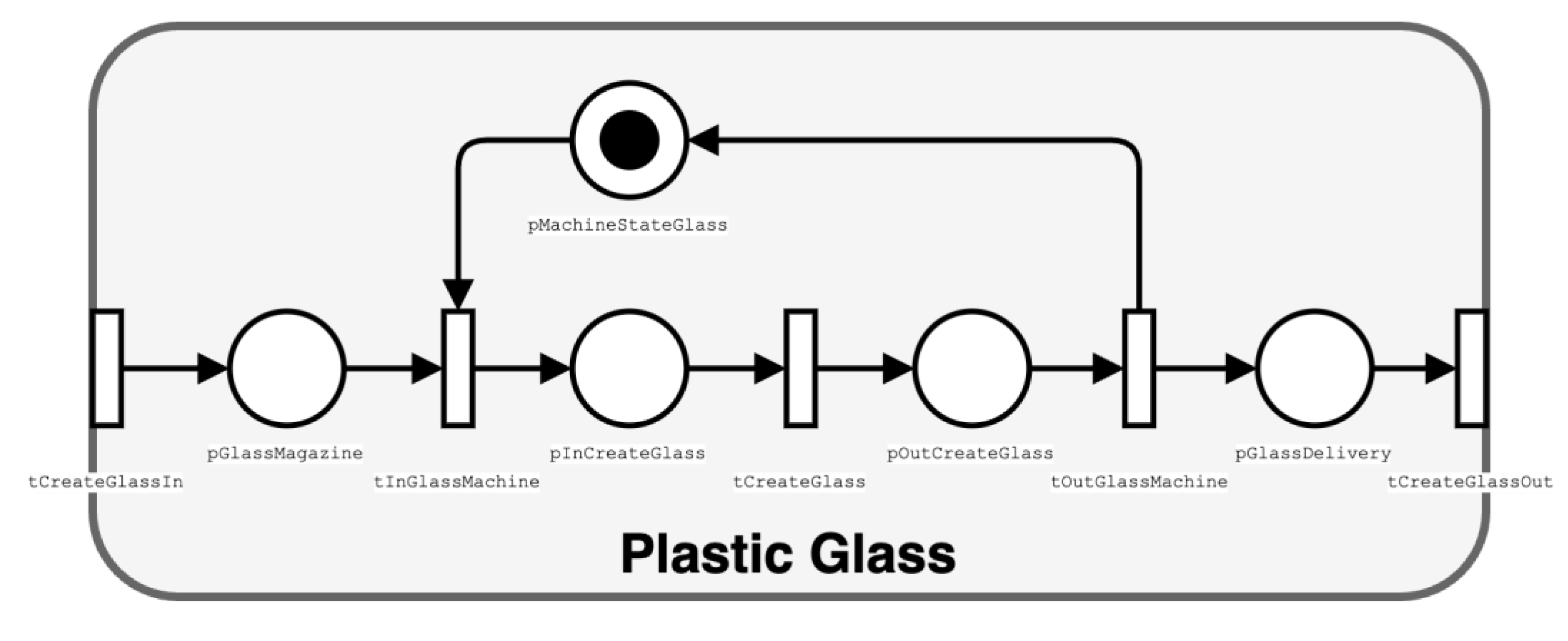
Figure 7 shows the Petri Module for “Plastic Glass”; the other three Petri Modules are similar, possessing the the same structure, as each of these jobs can be represented by a machine that takes a token, can work on that token, and isn’t available until after it is finished with the token. We will use the Petri Module Plastic Glass (
Figure 7) as an example to explain the mechanism.
Transition tCreateGlassIn works as the Input Port of the module. It will only accept tokens that have the ‘Plastic’ color from pAfterMat. The tokens with the color ‘Plastic’ will be put in pGlassMagazine. Transition tInGlassMachine will take a token from pGlassMagazine and from pMachineStateGlass and put one token in pInCreateGlass.
Place pMachineStateGlass represents the availability of the machine; if there is no token, that means the machine is currently unavailable. This way, any tokens in pGlassMagazine must wait until there is a token in pMachineStateGlass before the transtion tInGlassMachine can fire. Transition tCreateGlass represents the machine creating the plastic glass. When the transition is done, it will put the token in pOutCreateGlass, so pInCreateGlass and pOutCreateGlass represents before the machine is done with the plastic glass and after it is done. Transition tOutGlassMachine will put a token in pGlassDelivery for the finished plastic glass and a token in pMachineStatGlass to show that the machine is available. tCreateGlassOut will take the token out of the module and give it the color {‘windshield’, ‘createPlacticGlass}’, ‘combiner’. This will make sure the token will be sent to the combiner module.
4.2.3. Combiner
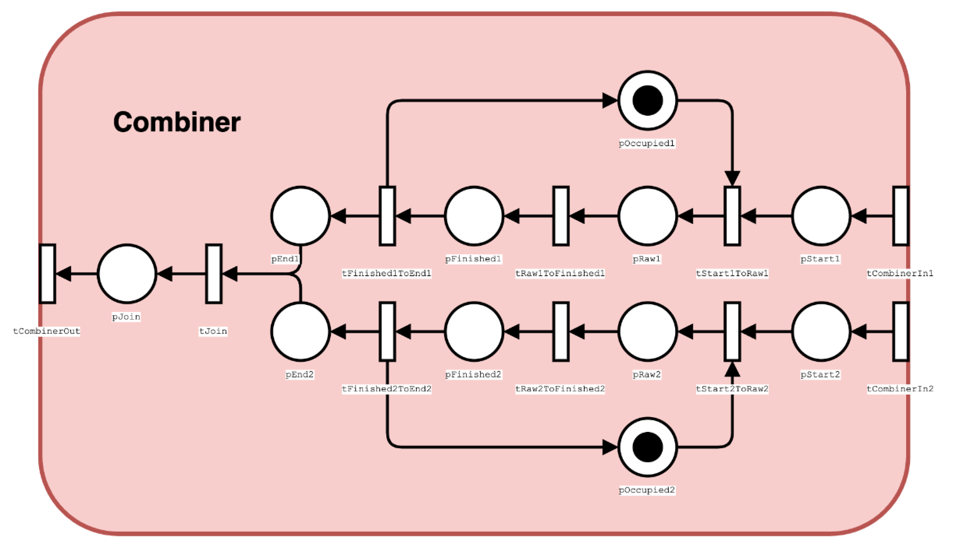
Petri Module Combiner represents an assembly machine that takes all the previously created parts like the upper body, the plastic glass, the tires and the bottom part to combine them into an unpainted car. The Petri Module is displayed in
Figure 8.
The Combiner module has two Input Ports, (tCombiner1In and tCombiner2In), one for the upper body and the glass, and the other one for the lower body and the tires. They take two tokens each of which, for input 1, one has to have the color “upperBody” and one has to have the color “windshield”, and for input 2 the two tokens have to have the colors “tires” and “lowerBody”, respectively. The transition deposits only one token, representing both materials.
The two machines who do the work on the top and the bottom half are represented similarly to how the CNC machines or the array of other processes was modeled in the previous section. pStartx represents the magazine before the machine starts working.
To simulate a worker loading the two machines, transition tStartxToRawx requests the resource ’Combiner_Worker’. Then again similar to how the machines were implemented before, the machine takes the raw material from the pRawx places, works on them in the tRawxToFinishedx transition and gets unloaded from pFinishedx, again by the worker to pEndx. The occupation of a machine is simulated by initializing pOccupiedx with one token which is returned when the machine is unloaded.
Then, the tokens from pEnd1 and pEnd2 are combined in the tJoin transition and placed in pJoin. Finally, tCombinerOut takes the token, gives it the colors {‘CarPutTogheter’, ‘combiner’, ‘painter’} and moves it to the IMC place pBeforeTravel to be picked up by the AGVs.
4.2.4. Fail Check
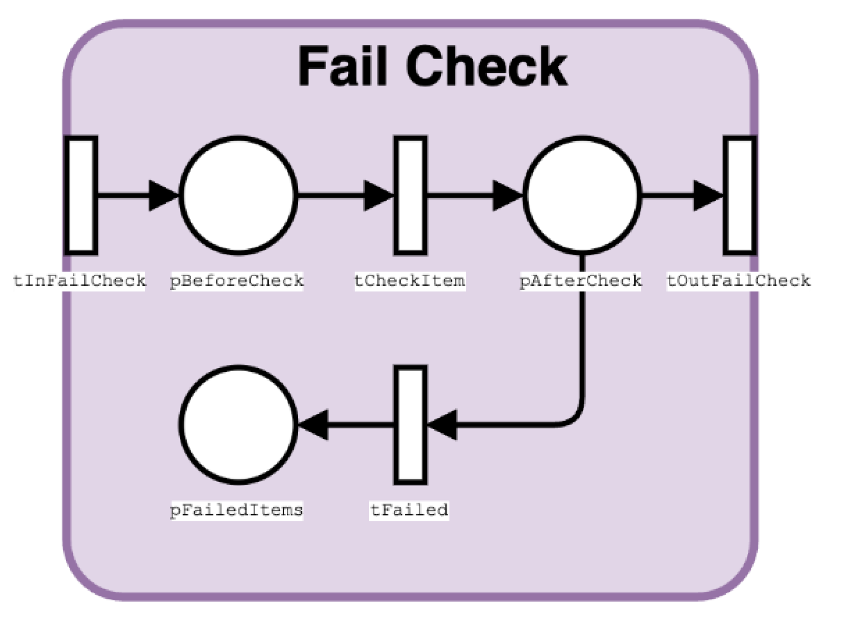
This Petri Module, shown in
Figure 9, represents the action of checking for errors in the final product. The Input Port tInFailCheck will only take tokens with the color ‘finished_car’ from place pAfterMat. The tokens will then be placed in pBeforeCheck.
As we don’t have any actual way to check if the car ’works’ properly in the simulation, the transition tCheckItem will just take a random number between 0 and 1, and if the number is over 0.8, the token will be assigned the color ‘error’. If the number is below 0.8, the token will get assigned the color ‘passed’. No matter which color it gets, the token will be placed pAfterCheck. From here, the tokens will either be taken bytOutFailCheck if they have the color ‘passed’, or taken by tFailed if they have the color ‘error’. This way, the output place of tOutFailCheck will contain all passed products, and pFailedItems will contain failed items. Hence, during the simulations and at the end of the simulation, We can then see how many tokens pass the test, and how many tokens fail it. While this may not have any real value, it is mostly to simulate the fact that not every product will be shipped to the public; some products will fail the quality check, and need to be thrown away or recycled.
5. Testing, Analysis, and Results
The model implementation on the MATLAB platform using GPenSIM resulted in many files. First, each Petri Module was implemented as a Petri Net Definition file. Also, for each Module, there was a modular pre-processor file for implementing the additional logic conditions for firing of enabled transitions. There were also some modular post-processor files for coding the post-firing actions
Due to brevity, the implementation of the model (coding) is not presented in this paper. The complete code is available for any interested readers, along with a more detailed (technical) report and a user guide.
5.1. Sample Run
Figure 10 shows the number of AGVs moving is mostly between 6 and 8.
Figure 10 also shows that most of time, there is only one AGV at the charging station, and rarely two AGVs. Also, nearly all the AGVs are active until the end of the simulation in which more AGVs become idle one after the other.
In
Figure 11, we can see the inventory at the warehouse, number of products passed the quality control, and how many failed over time. We can see that all materials are out of the warehouse at time step 100, and are being worked on in the production line. The first product is not finished until around 275-280 time steps, at which the first product gets approved, not many time steps after, the first failed one arrives.
5.2. Studying the Impact of Battery
We simulated six runs using different combinations of the values for the batteryConsumpt3i65onR and the number of charging stations. We started with a baseline system where the AGVs had relatively robust batteries with a battery consumption rate of 0.5% per time unit and only four available charging stations. Then we increased the battery consumption rate to 1% for every time unit, this time with 5 charging stations. Finally, we increased the battery consumption rate to 1.5% per time unit, which simulates a weaker AGV battery.
Case 2: 1% battery consumption rate, 5 charging stations
In
Figure 12, we can see how the increased battery consumption rate lead to the need for the AGVs to be charged twice, in order to transport all material. Comparing
Figure 13 to the previous run with only 0.5% battery consumption rate, we can see that at time step 350, when the production in Case one had its maximum output per time unit, the production in case 2 just starts to warm up.
5.2.1. Case 3: 1.5% Battery Consumption Rate, 5 AGVs
Figure 14 shows how the increase in battery consumption rate to 1.5% causes the AGVs to be using a charging station almost constantly. This time the 400 time steps of the simulation were not enough to turn all material tokens into the final product. Important to note is also the the production rate seems to have been lowered.
Figure 14 clearly shows that increasing the battery consumption rate greatly impacts the system performance.
5.2.2. Case 4: 2% Battery Consumption Rate, 4 Charging Stations
In this case we can see how the AGVs, displayed in
Figure 16, run out of charge while moving and never reach their goal. The production stands still. No final product is produced as shown in
Figure 17.
The simulation framework allows for many more experimental setups like choosing a variable amount of AGVs or increasing the materials so that the production will continue for longer.
6. Discussion
The novelty of this paper lies in its approach to simulating AGVs in a production line environment, specifically designed for the assembly of toy cars. This study stands out in its detailed focus on two critical operational parameters: the battery charge reduction rate of AGVs and the number of charging stations available in the production line. Unlike previous studies that have primarily concentrated on general path planning or bottleneck detection in manufacturing systems, our research delves into the intricate balance between AGV operational efficiency and the logistical constraints imposed by battery life and charging infrastructure.
By varying the battery charge reduction rate, we explore how different energy consumption models affect the overall productivity and efficiency of AGVs. This aspect is crucial in understanding the real-world implications of battery technology advancements on AGV operations. Furthermore, the investigation into the optimal number of charging stations addresses a significant logistical challenge in AGV deployment, providing insights into how production lines can be designed or modified to maximize AGV uptime and throughput.
Additionally, the use of a toy car production line as a test-bed adds a unique dimension to our study. This controlled, yet realistic, environment allows for a detailed examination of AGV dynamics in a manufacturing setting, offering valuable data that can be extrapolated to larger, more complex production systems. The findings from this study have the potential to inform future designs and operational strategies for AGV-integrated production lines, particularly in industries where precision and efficiency are important.
6.1. Limitations of This Work
While our study provides valuable insights into the simulation of AGVs in a production environment, it is important to acknowledge certain limitations. Firstly, our model does not account for the distance traveled by an AGV when it moves between different points in the production line. In the current setup, AGVs are assumed to instantly appear at the required location without consuming battery power or covering any actual distance. This simplification overlooks the potential impact of travel distance on battery consumption and overall efficiency.
Another notable limitation is the absence of a director module in our current framework. Such a module could significantly enhance the operational dynamics by managing he stock of materials and semi-finished products, and directing AGVs for efficient resource allocation and transportation within the production environment.
Furthermore, our Petri net model primarily focuses on a specific segment of the manufacturing process. Extending this model to encompass other stages, such as shipping, could provide a more comprehensive view of the entire product life-cycle, from creation to sale.
Funding
“This research received no external funding”
Conflicts of Interest
“The authors declare no conflicts of interest.”
References
- Giglio, D.; Paolucci, M. Agent-based Petri net models for AGV management in manufacturing systems. IEEE 2001.
- Shuhua, H.; Kuei-Huang.; Lin, M. On Some Basic AGV Traffic Control Structures Modeled by Petri Nets. Engineering Journal of National Taiwan University 1993, pp. 113–124.
- Hernandez-Martinez, E.G.; Foyo-Valdes, S.A.; Puga-Velazquez, E.S.; Campana, J.A.M. Motion Coordination of AGV’s in FMS using Petri Nets. In Proceedings of the IFAC Symposium on Information Control Problems in Manufacturing, 2016.
- Zhang, Y.; Peng, E.; Luo, Z.; Zeng, L.; Li, C. Bottleneck detection for discrete manufacturing system based on object-oriented colored petri nets and cloud simulation. In Proceedings of the ITM Web of Conferences, 2022. [CrossRef]
- He, Z.; Zhang, R.; Ran, N.; Gu, C. Path Planning of Multi-Type Robot Systems with Time Windows Based on Timed Colored Petri Nets. Applied Sciences 2022. [CrossRef]
- Hongyuan, Z.; Zongde, F.; Weiping, F.; Huili, W. AGV path planning method based on Petri net. Combined machine tools and automated machining technology 2001, 000, 21–24.
- Xiaolong, R.; Haoyu, W.; Hua, L. Research on multi-AGV optimal path method for undirected Petri nets. Journal of Xidian University 2008.
- Murata, T. Petri nets: Properties, analysis and applications. Proceedings of the IEEE 1989, 77, 541–580.
- Peterson, J.L. Petri net theory and the modeling of systems; Prentice Hall PTR, 1981.
- Davidrajuh, R. Petri Nets for Modeling of Large Discrete Systems; Springer, 2021.
- Davidrajuh, R. Modeling Discrete-Event Systems with GPenSIM; Springer International Publishing: Cham, 2018. [CrossRef]
- GPenSIM. General-purpose Petri Net Simulator. Technical report, http://www.davidrajuh.net/gpensim, 2019. accessed on 20 July 2020.
- Davidrajuh, R. Colored Petri Nets for Modeling of Discrete Systems: A Practical Approach With GPenSIM; Springer Nature, 2023.
|
Disclaimer/Publisher’s Note: The statements, opinions and data contained in all publications are solely those of the individual author(s) and contributor(s) and not of MDPI and/or the editor(s). MDPI and/or the editor(s) disclaim responsibility for any injury to people or property resulting from any ideas, methods, instructions or products referred to in the content. |
© 2024 by the authors. Licensee MDPI, Basel, Switzerland. This article is an open access article distributed under the terms and conditions of the Creative Commons Attribution (CC BY) license (http://creativecommons.org/licenses/by/4.0/).
