1. Introduction
In order to achieve higher flight performance, morphing wing technology has become a hot research topic in aviation science and technology. Morphing wing technology is one of the important ways to improve aerodynamic efficiency. Its purpose is to maintain the optimal shape of the morphing wing according to the requirements of the real-time flight mission and flow field conditions through accurate active deformation, under the premise of ensuring the safety of the aircraft structure [
1]. A variable camber wing is the wing with flexible leading and trailing edges and a continuous, smooth surface without slots or sliding joints. The wing airfoil is controlled by internal linkage to vary with the environment and the required lift [
2,
3]. The smooth, continuously variable camber wing can delay airflow separation, reduce drag and significantly improve aircraft performance. The key technologies involved are mainly: small fast response intelligent drive technology and continuous deformable skin technology [
4]. The research on variable camber wing mainly focuses on aerodynamic requirement analysis [
5,
6], intelligent flexible skin [
7,
8,
9,
10,
11,
12,
13,
14,
15,
16,
17,
18], lightweight actuator[
19], mechanical analysis[
20,
21,
22,
23,
24,
25]. In recent years, with the development of research, the leading edge of variable camber wing is developing towards solving the practical problems of engineering, that is, solving the problems of aeroelasticity, fatigue durability, bird impact resistance and de-icing in practical engineering applications [
26].
Numerous experimental verifications had been conducted both domestically and internationally to promptly implement the variable camber wing to the model. The DLR had conducted extensive research on variable wing leading edge, covering structural design and optimization [
27], functional verification of target deflection angle. To measure the strain of the flexible skin, non-contact measurement and strainmeter measurement are used [
28]. The deformation of the flexible skin was reconstructed, and a ground bending test was planned [
29]. The Italian Aerospace Research Center (CIRA) conducted an experimental study on reconstructing the trailing edge of a deformed wing in a wind tunnel [
30]. Between 2010 and 2015, Europe conducted the SARISTU project. The project involved designing and manufacturing a full-scale wing with a wingspan of 4.7 meters, which included the leading edge, trailing edge, and winglet with variable camber. The Russian Central Research Institute of Aerohydrodynamics (TsAGI) conducted tests in the T-104 wind tunnel to examine the deformation function of the leading and trailing edges with variable camber during takeoff and landing [
26]. The China Aircraft Strength Research Institute has been following the design, optimisation and test verification of the variable camber wing for a long time, and has carried out detailed work on the design optimization of the variable camber wing leading edge [
31,
32,
33]. Unlike the traditional rigid wing structure, the intelligent variable camber wing structure has the characteristics of flexibility, large deformation and adaptive change. In order to accurately simulate the deformation and load bearing of the variable camber wing under different working conditions, and to evaluate the deformation function and strength of the wing, it is necessary to solve the problems of loading, control and measurement according to the actual structural characteristics and validation requirements.
In this paper, the deformation function and load capacity verification of the leading edge of a full-scale variable camber wing were studied. By establishing an accurate mathematical model, a followed-up load test apparatus was designed. A multi-point cooperative control system was developed through motion simulation and sensor network design technology. A distributed sensor monitoring network was formed by many advanced measurement methods and structural configuration reconstruction technology. The motion function and structural strength of the leading edge structure of the variable camber wing were verified and evaluated by tests.
2. Characteristic Analysis of Leading Edge Strength test of Variable Camber Wing
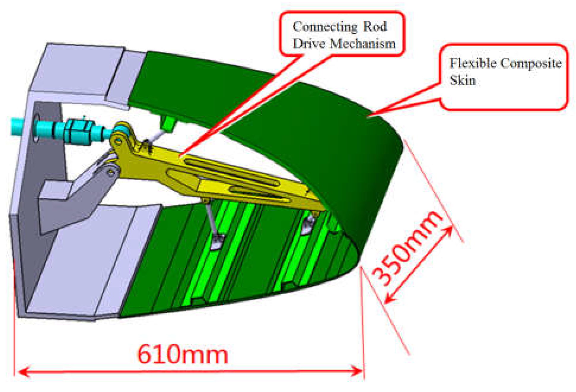
The test piece model of the variable camber wing leading edge is shown in
Figure 1 and consists mainly of a mechanical drive link mechanism, composite fiberglass skin and stringers. There are two main purposes of the test: to verify the motion function of the test piece and monitor the deformation, to verify whether the leading edge test piece meets the design objective of the downward deviation of the aerodynamic shape by 17°, and analyze the deformation accuracy; to verify whether the strength of the leading edge test piece meets the design load requirements.
The test differs from the traditional wing test in three main ways. First, when the leading edge is in deflection motion, there is no fixed motion trail, and the motion trail of the test piece is unknown. After converting the aerodynamic load into the test load of the upper and lower wing surface, the motion trail of the upper and lower wing surface load points is also non-linear. Secondly, the test piece is deformed by connecting the mechanical drive mechanism with the deformation drive device, and the upper and lower wing surface load points simulate the flight load. There is a cooperative relationship between the deformation of the test piece and the loading load. Both of these features pose challenges for the precise control of the test and the design of the co-loading. In addition, it is difficult to monitor the deformation of the specimen and reconstruct the shape of the flexible skin because the deformation of the specimen is large during the motion process and the flexible skin of composite materials may be deformed locally or suddenly.
3. Test Scheme Design
3.1. Design of Follow-Up Loading Test Device
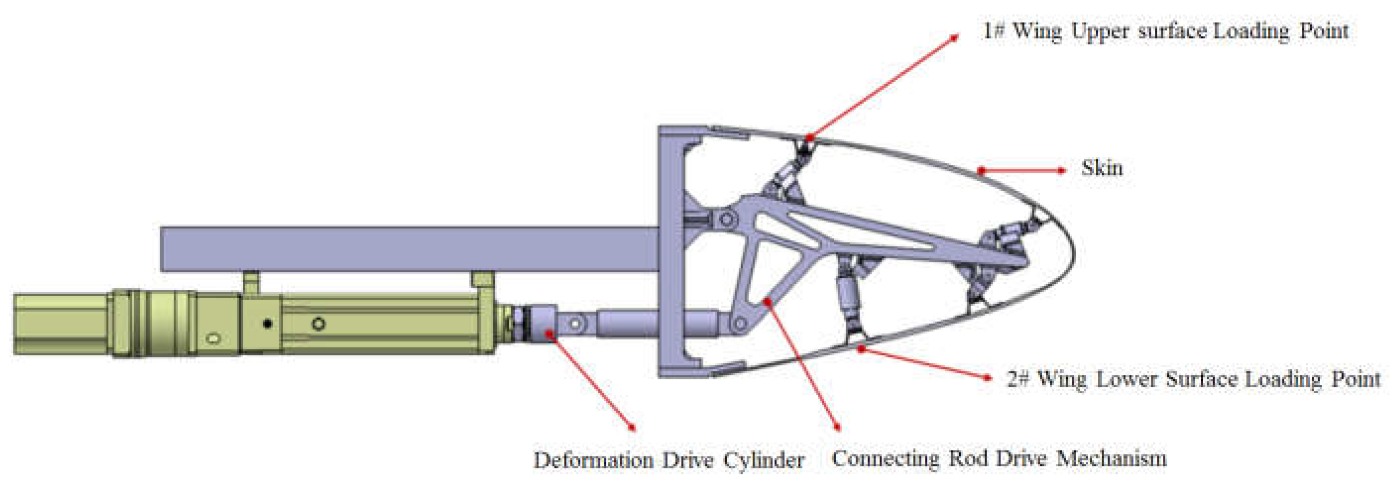
In order to solve the loading difficulty caused by the unknown motion trail of the specimen and the non-linearity of the motion trail of the loading point, the loading point of the specimen was determined to be the skin surface corresponding to the upper and lower wing surfaces near the first stringer at the root by finite element analysis, as shown in
Figure 2. Based on the principle of the vector loading method, a follow-on loading device was designed, as shown in
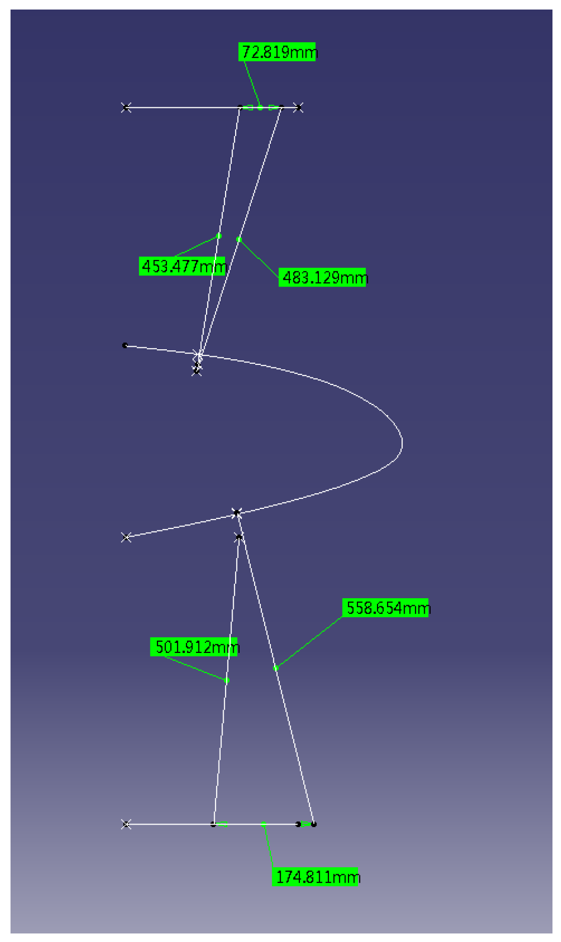
Figure 3, the loading direction of the loading cylinder was adjusted through the expansion of displacement compensating cylinder along the normal direction of the skin in real time. The kinematic model was established to analyse the movement envelope range of the specimen and the movement range of the loading point was calculated, as shown in
Figure 4. Based on this, the stroke of the displacement compensating cylinder and the loading cylinder are selected, and the motion trail of the loading point of the upper and lower wing surfaces was fitted.
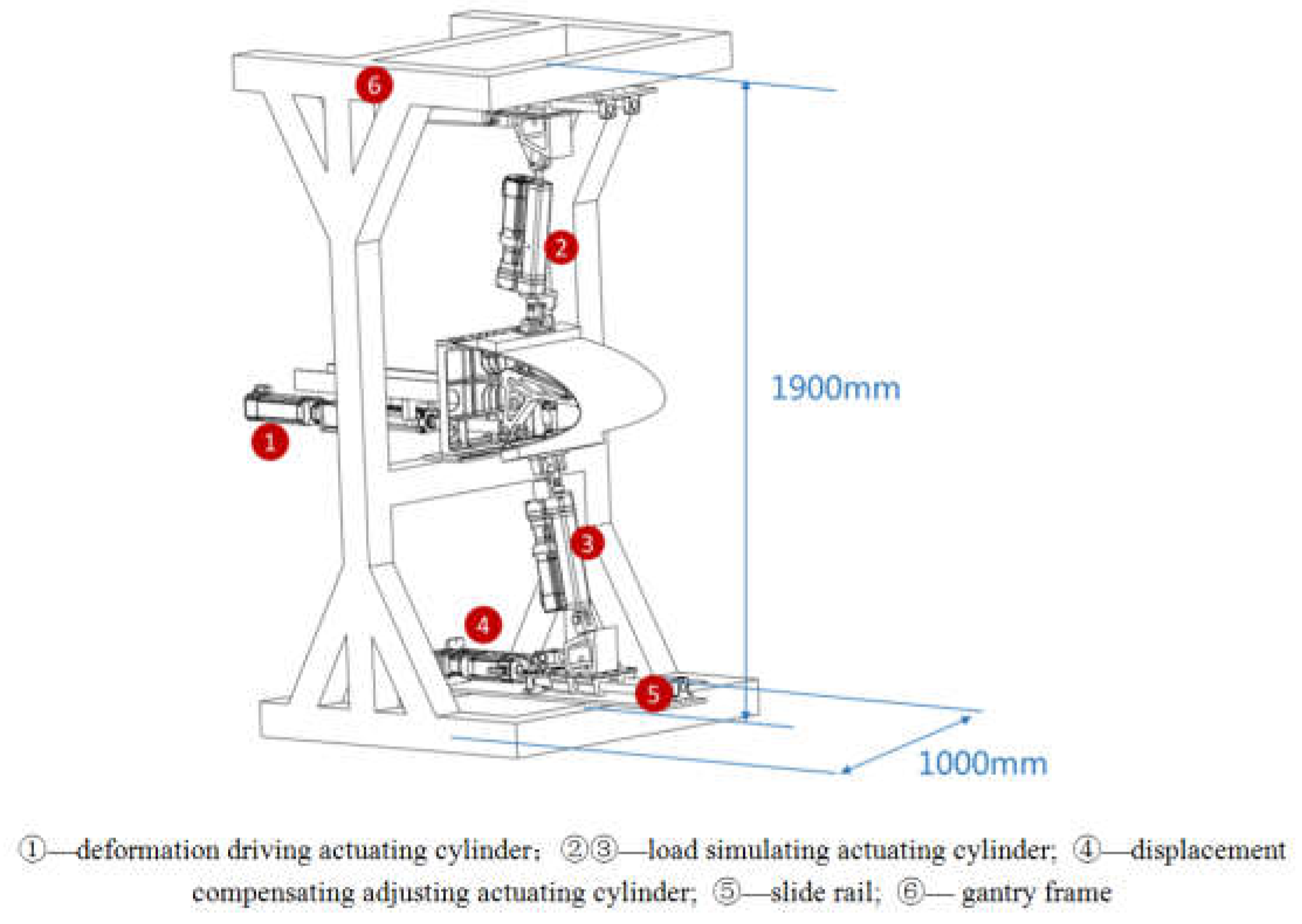
Based on the above analysis, the design of the variable camber wing leading edge strength test device is shown in
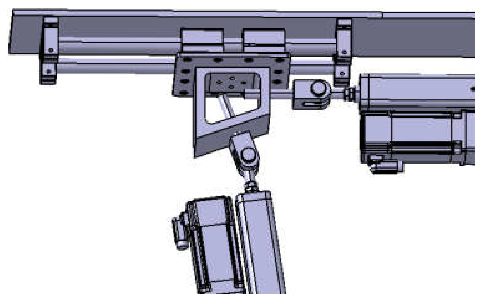
Figure 5. the deformation driving actuating cylinder is connected to the link mechanism by a hinge and makes a reciprocating motion in the horizontal direction, and drives the link mechanism to drive the skin to realise the leading edge deflection. The loading points of the upper wing surface and the lower wing surface are connected to one end of the loading actuating cylinder. The gantry frame is used to fix the test specimen and the loading equipment, and the gantry frame is fixed on the ground by connecting the ground rail and with the anchor bolts. As shown in
Figure 6, a group of slide rail structures is arranged on the upper and lower sides of the gantry frame respectively, each group of slide rail structures consists of two slide rod and four slide blocks, and ball bearings are built in the slide blocks to ensure smooth movement without sticking; one end of the slide rail is connected to the displacement compensation adjusting actuating cylinder to make it extend and contract in the direction parallel to the slide rail, and the other end is connected to the loading cylinder to adjust the loading direction by way of displacement compensation to the adjusting actuating cylinder.
3.2. Multi-Point Cooperative Closed-Loop Control Technology
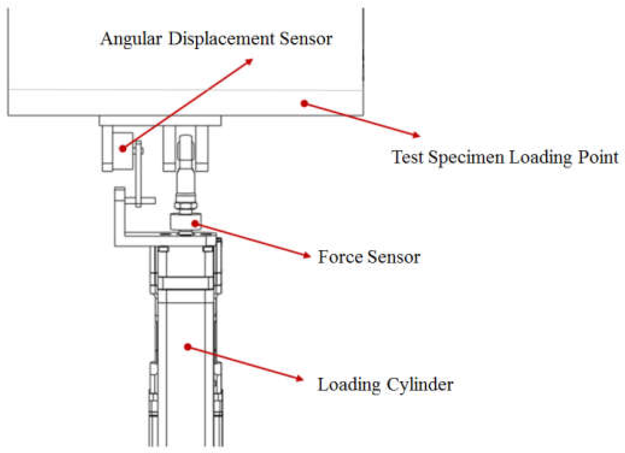
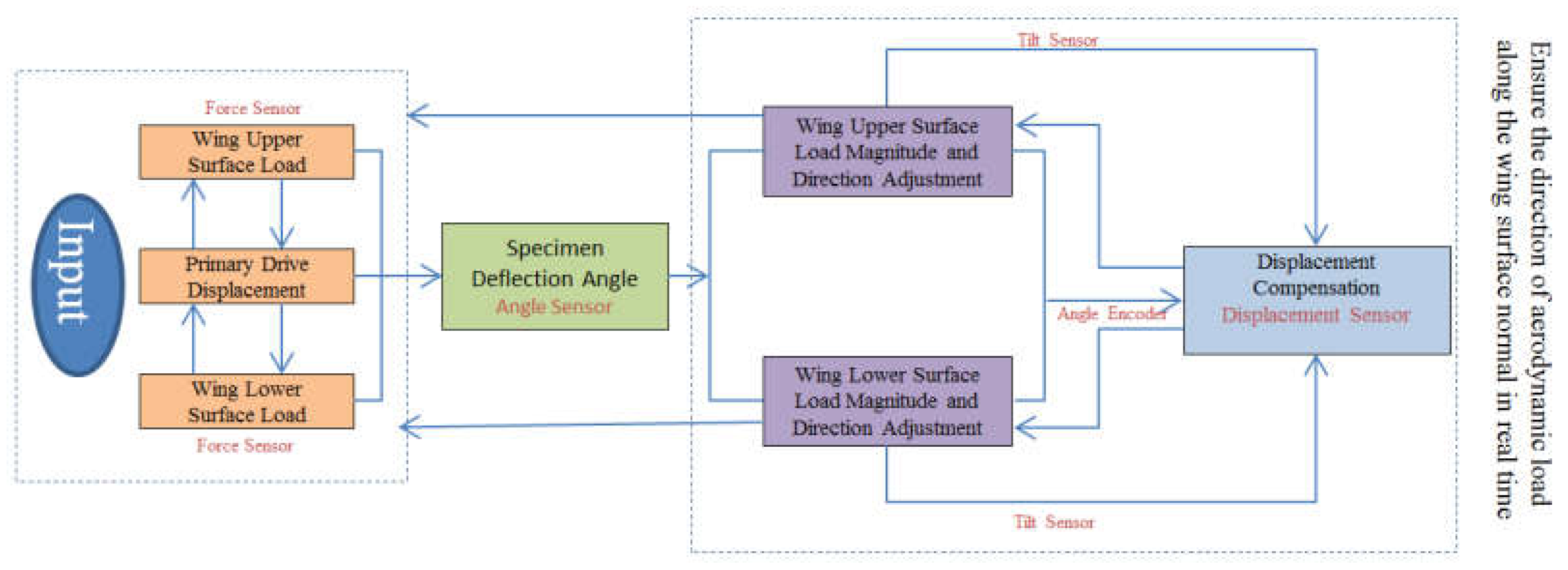
In the test, it is necessary to control the deformation driving actuating cylinder, the load simulating actuating cylinder and the displacement compensating adjusting actuating cylinder to make the deformation of the test piece correspond to the aerodynamic load in real time, and the load direction is along the normal direction of the wing surface in real time. In order to solve the control problem, an angle measuring instrument was set on the driving link of the test piece to record the deflection angle of the test piece in real time. The deformation driving cylinder adopts position control to output the deformation amount in real time, and a functional relationship was established between the displacement amount of deformation driving actuating cylinder output and the deflection angle of the test piece. The loading actuating cylinder adopts force control, an angular displacement sensor and a force sensor are arranged between the loading actuating cylinder and the loading point as shown in
Figure 7, the angular displacement sensor converts and outputs the angle between the loading cylinder and the wing surface in real time, and the force sensor outputs the actual load in real time. The displacement compensation adjusting actuating cylinder adopts position control, adopts a displacement compensation mode to adjust the loading direction in real time, and performs closed-loop control between the loading angle and the loading direction. A multi-point cooperative closed-loop control system was developed, the motion trail of a test piece obtained by kinematics simulation is used as the initial value input to the control system, and the output of the control system automatically tracks the input amount by iterative mode, reduces the tracking error, improves the control accuracy, suppresses the influence of disturbance signals, ensures the accuracy of the test control loading and realize the real-time data acquisition and real-time output of the curve. The closed-loop control principle of the test is shown in
Figure 8.
3.3. Design of Sensor Monitoring Network
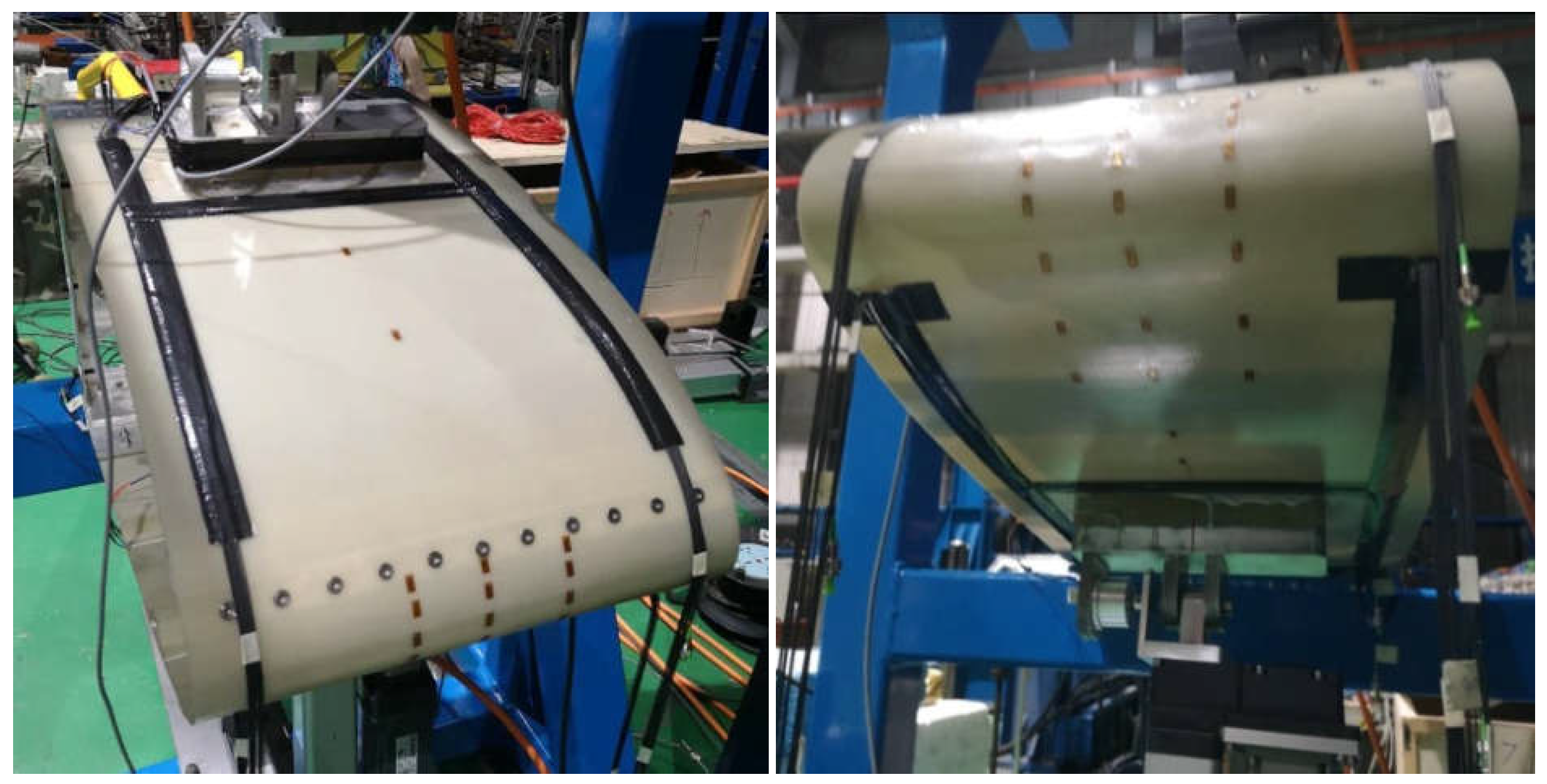
Aiming at the demand of measuring and controlling the motion deformation of the test piece, a complementary sensor monitoring network was designed, taking into account the large deformation amount of flexible skin, abrupt change of local deformation. The shape reconstruction method of wing leading edge with variable camber based on FBG sensor is adopted to meet the requirement of real-time deformation measurement of the test piece. The application scenario of the FBG sensor in the test is shown in
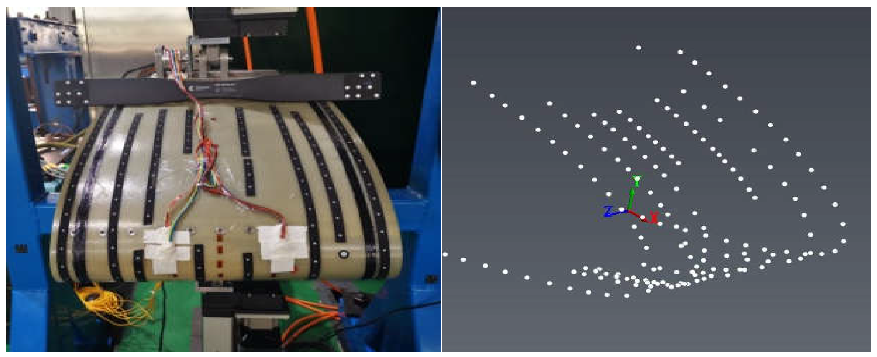
Figure 9. Using photogrammetry and triangulation of optical photo imaging, the spatial positions of measuring points under different deflection angles are captured, and the leading edge shapes of variable camber wings corresponding to deflection angles are reconstructed through coordinate transformation and data processing to realize real-time output and comparison of wing shape. The application scenario of the photogrammetry system in the test is shown in
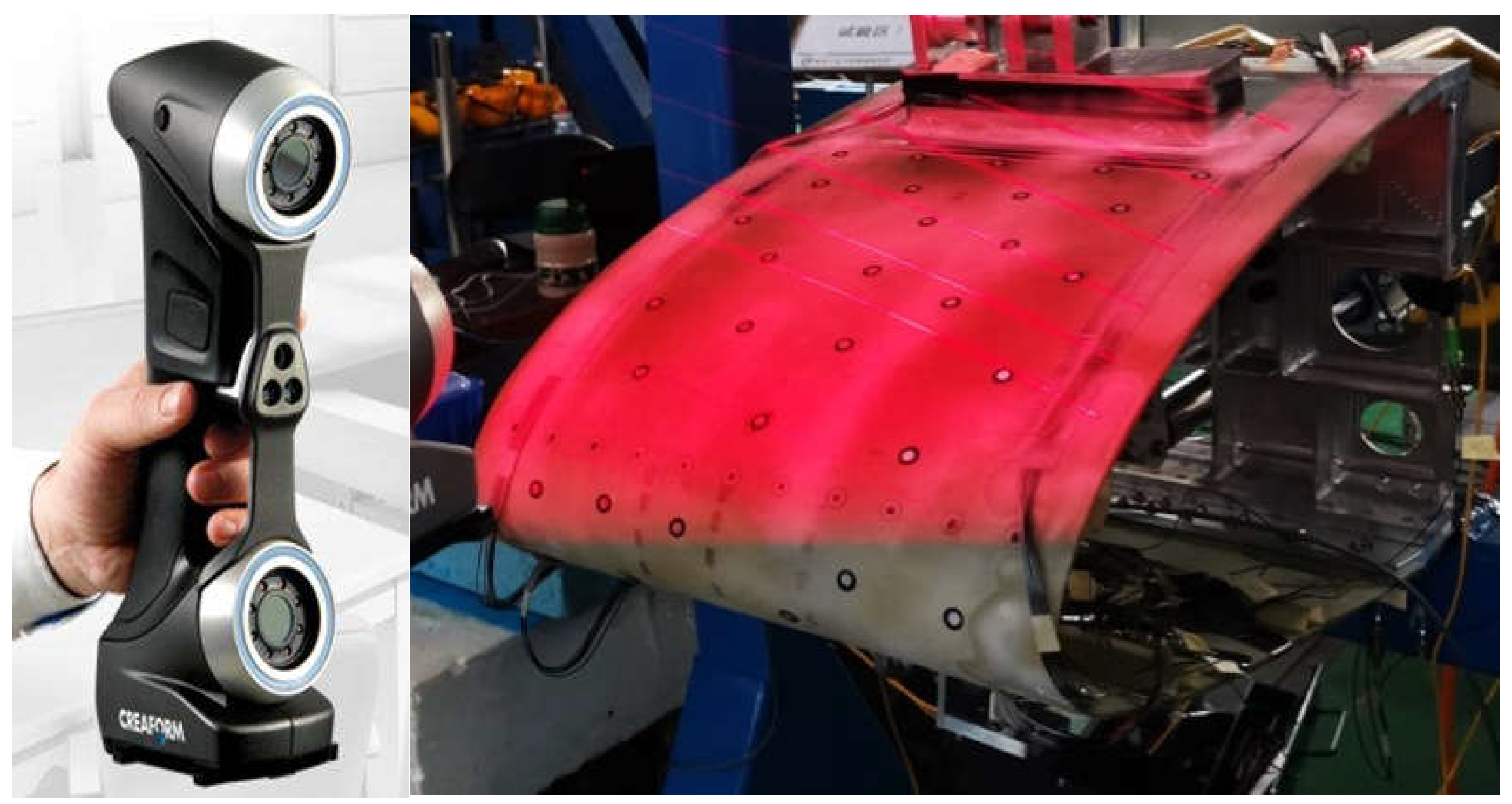
Figure 10. The three-dimensional deformation of the test piece is measured by the three-dimensional fast scanning method, and the law of spanwise deformation and local deformation are monitored. The application scenario of the three-dimensional fast scanning system in the test is shown in
Figure 11.
4. Leading Edge Strength Test of Variable Camber Wing
4.1. Test Piece
The leading edge test piece model is derived from a particular type of remote aircraft. The chord of this model is 610mm derived from the leading edge of the aircraft, and span is 350mm. The design target of the aerodynamic deflection angle of the test piece is 17.5°, which corresponds to the maximum downward deflection of the leading edge structure of 15°. The deflection angle in the test is the deflection angle of the leading edge structure.
4.2. Test Load
The test load of the leading edge of the variable camber wing depends mainly on the design and application of the aircraft. The test piece is deformed by driving cylinders in the motion function test and the upper and lower wing surfaces are not loaded. The strength test load is derived from the results of the aerodynamic analysis, which is equivalent to the test load applied to the upper and lower wing surfaces. The corresponding relationship between deformation driving cylinders displacement, structural deformation angle and test load is shown in
Table 1.
4.3. Test Loading
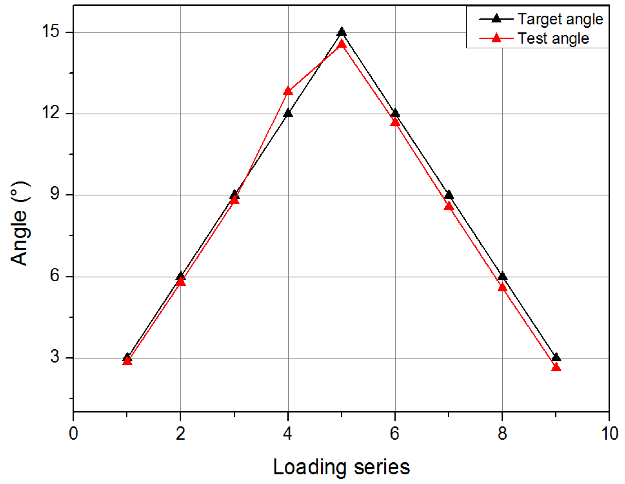
In the motion function test, the loading point of the upper and lower wing surface was followed-up, the load was always kept at zero, the deformation driving cylinder drived the test piece to deflect, and the error between the actual deformation of the test piece and the design theoretical value was mainly concerned. The contrast curve of the measured deflection angle and the theoretical deflection angle is shown in
Figure 12. The average control error of the deflection angle in the function test of the leading edge motion of the variable camber wing is 4.59%.
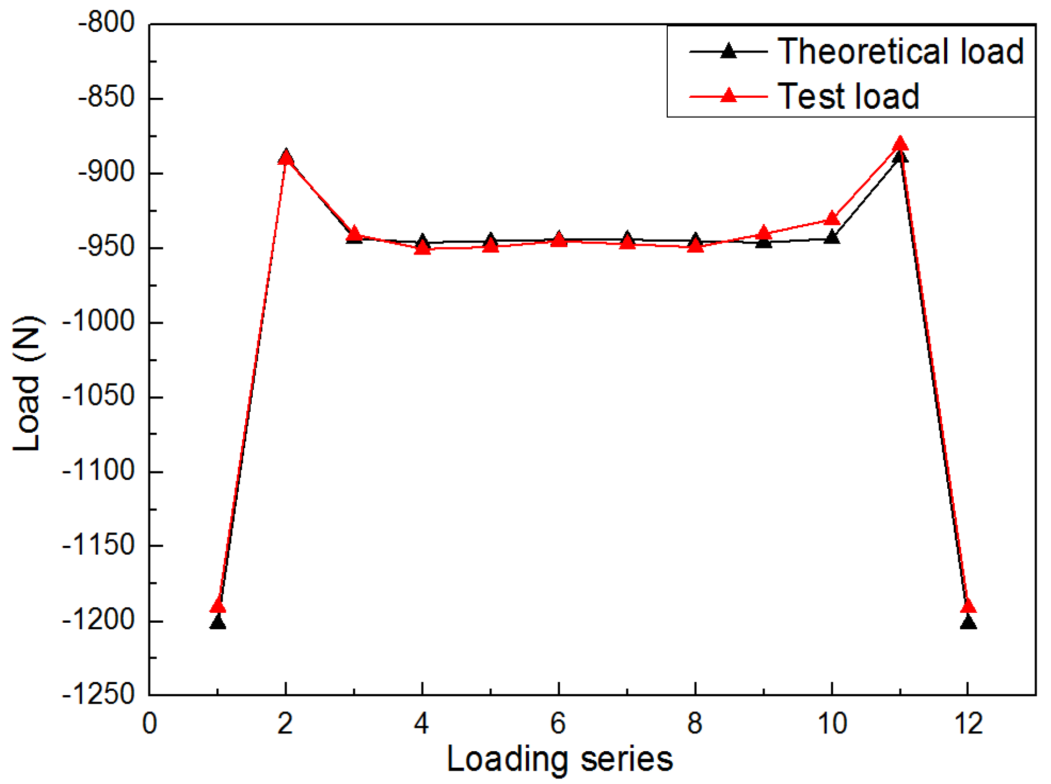
In the strength verification test, the upper and lower wing load points followed the dynamic load, and the load direction was in real time along the normal direction of the wing surface; The load of the upper wing surface is large and is the main loading point. The average error of the upper surface load is 0.54%. The contrast curve of the load is shown in
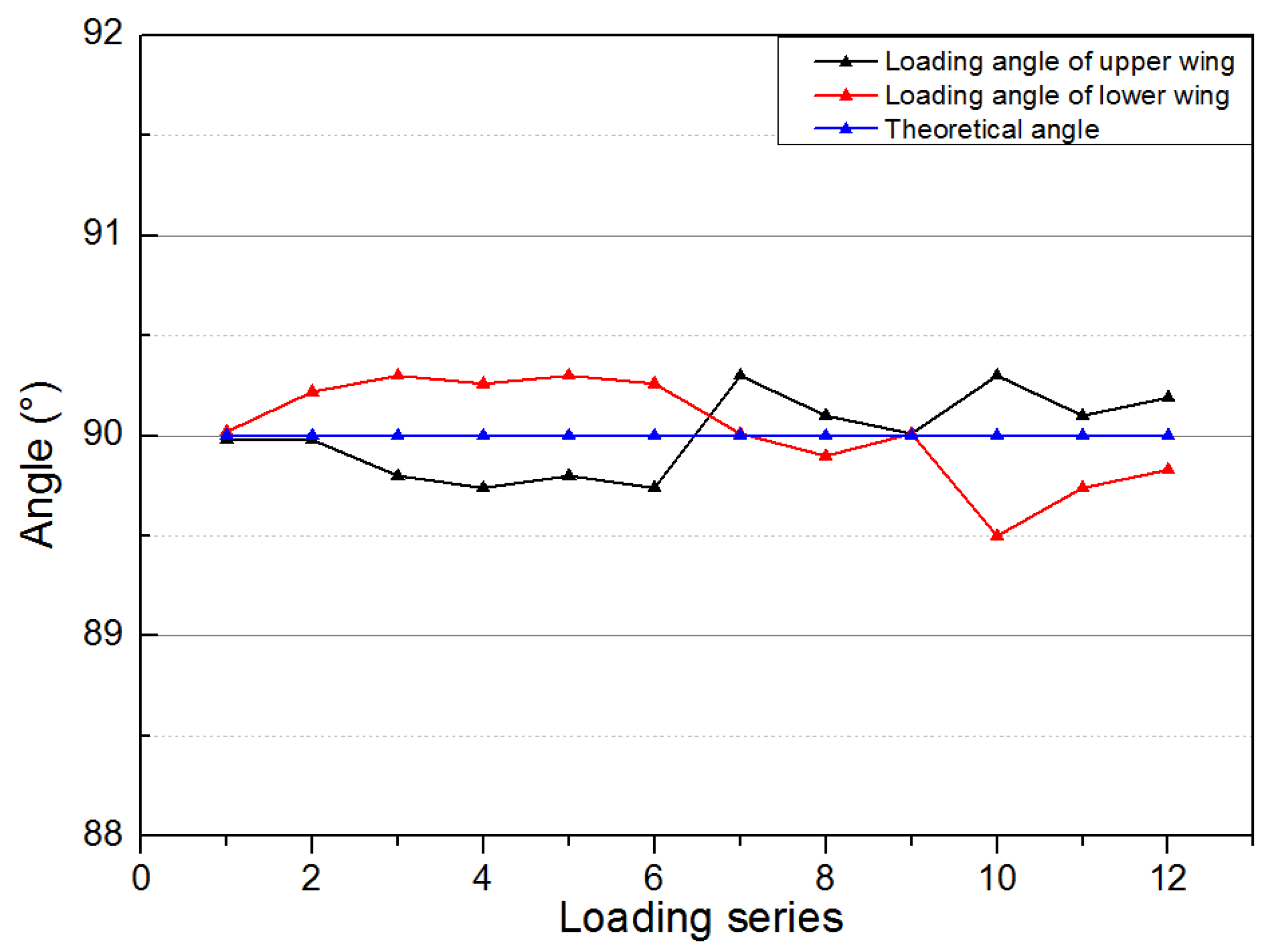
Figure 13. The average error of the load applied angle is 0.24% and the comparison curve of the load angle is shown in
Figure 14. It can be seen that the variable camber wing leading edge test device accurately simulated the deformation process of the leading edge under real flight and driving loads.
4.4. Test Results and Analysis
In the process of motion function test, the composite skin deformed smoothly and continuously, and the joint between the skin and the stringers did not debond; all the connecting parts of the test specimen were normal without abnormal noise, and the mechanical connecting rod drive structure deformed smoothly without blocking.
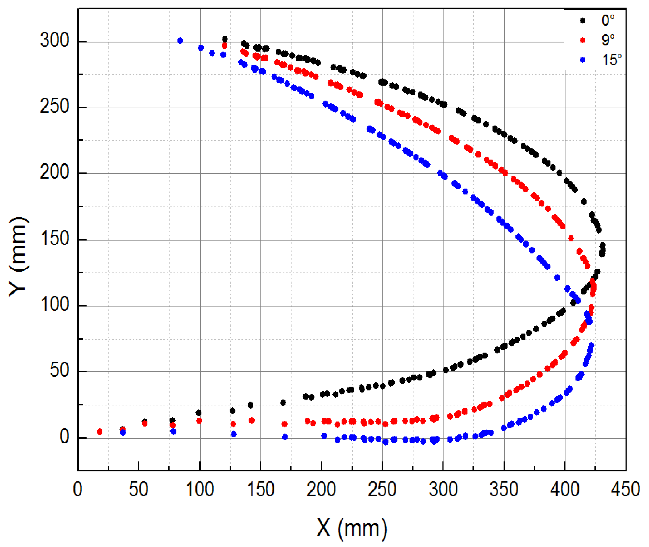
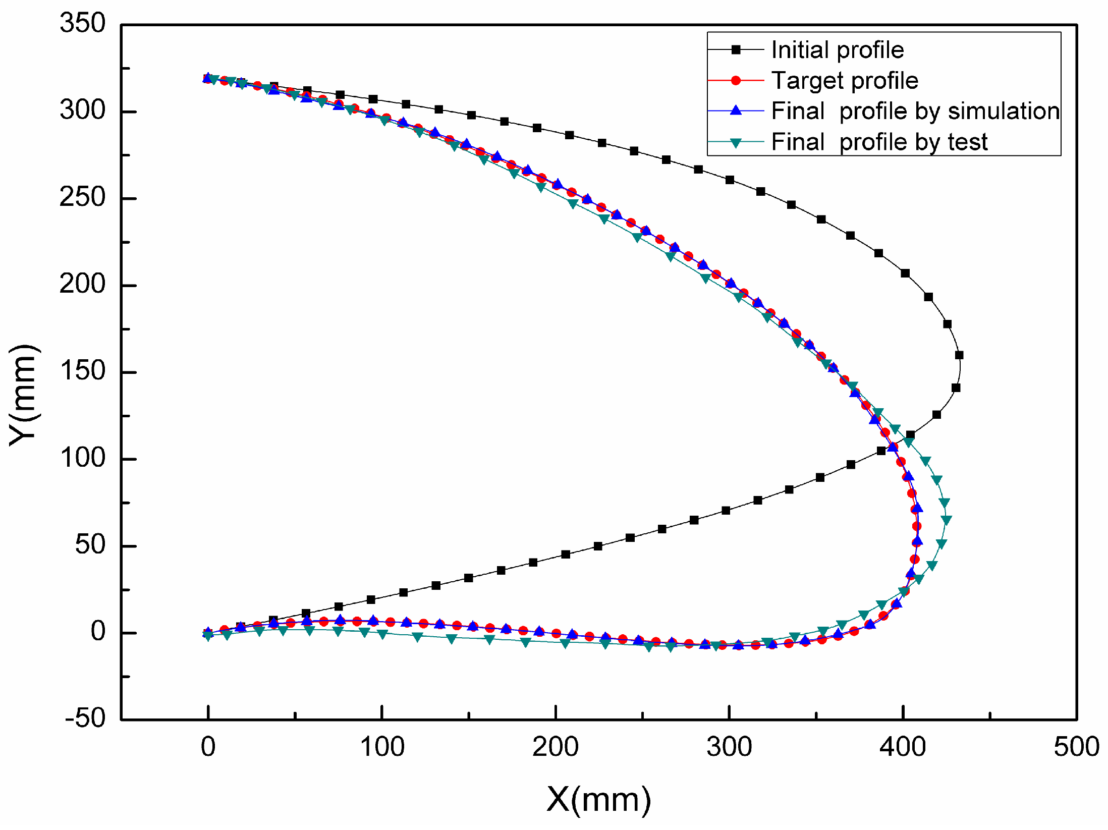
Figure 15 and
Figure 16 show the shape change curve of the leading edge and the deformation accuracy curve when the leading edge structure was lowered by 15% in the motion function test, respectively. It can be seen that the leading edge test piece meets the design target of the aerodynamic shape downward by 17°; when the leading edge structure is deflected downward by 15° (the aerodynamic shape is deflected downward by 17.5°), the difference between the leading edge tip deformation and the theoretical deformation is the largest, and the maximum deformation error is less than 10mm.
In the process of strength verification test, the deformation of the composite skin is smooth and continuous, and the joint between the skin and the stringers did not debond. All connecting parts of the test piece were normal without abnormal noise; mechanical connecting rod drive structure deformed smoothly without blocking; no damage occurred to the structure.
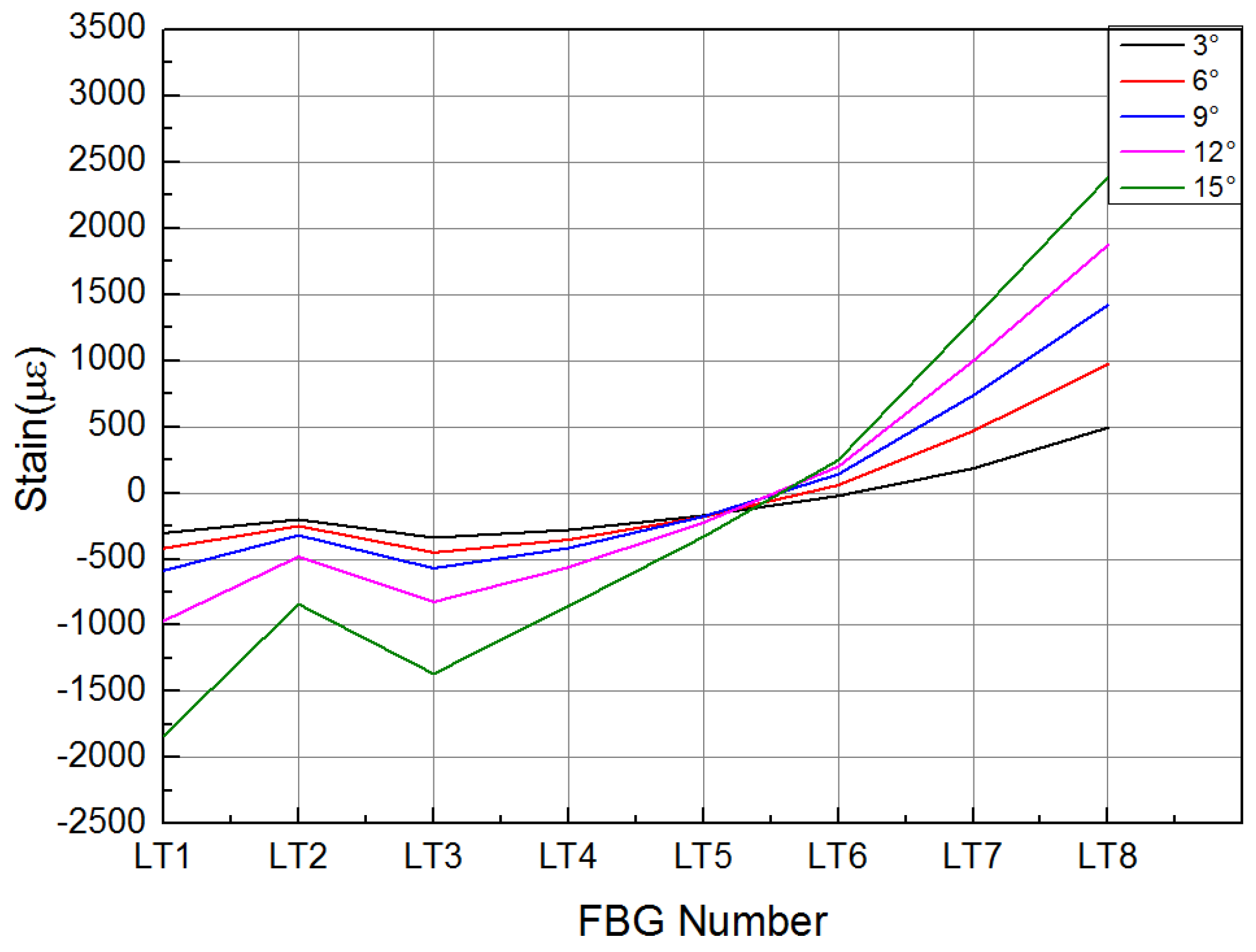
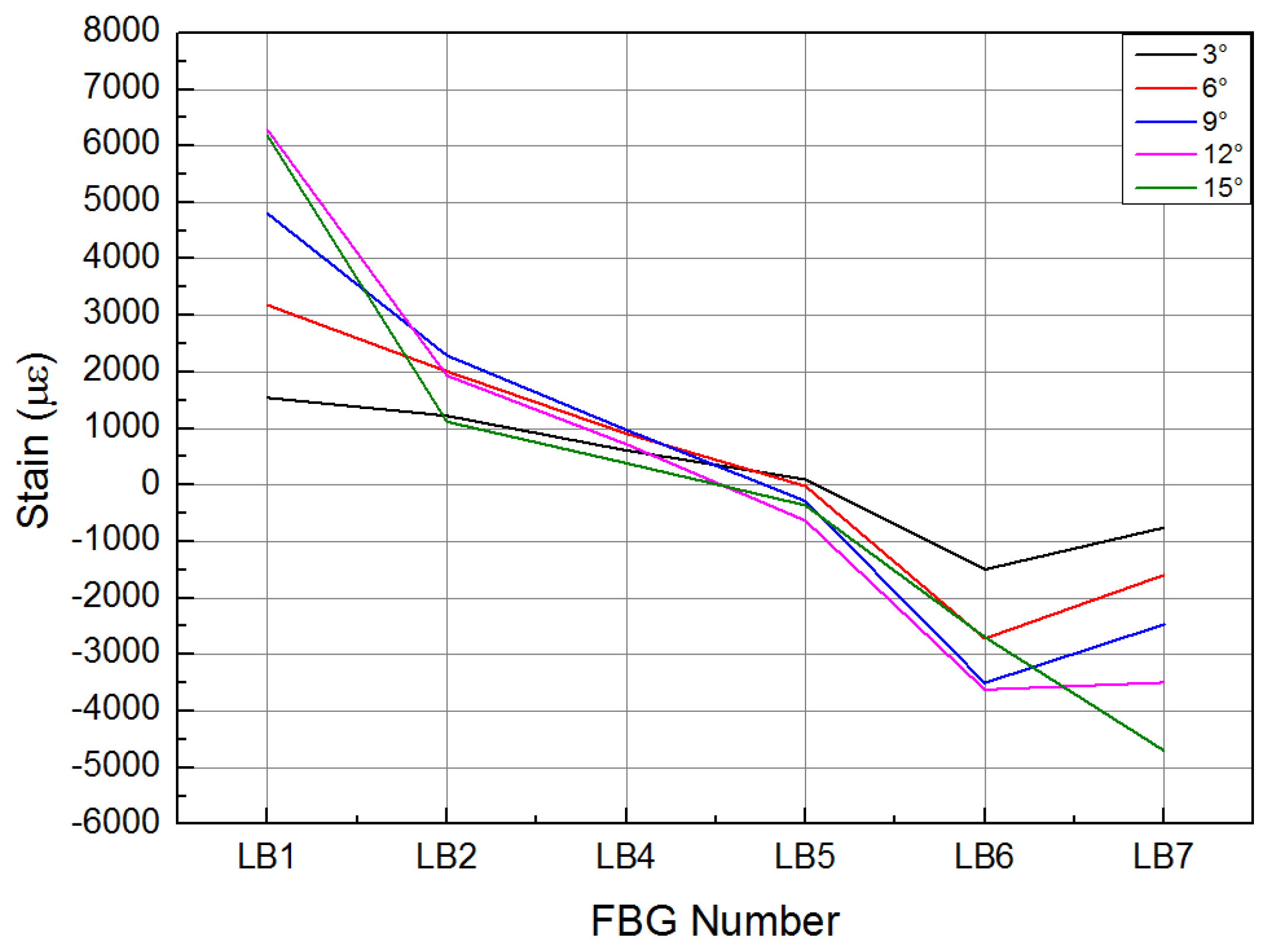
Figure 17 and 18 show the strain curves of the upper and lower wing surface under different leading edge deflection angles, respectively. According to the FBG sensor arrangement scheme in
Figure 19, it can be seen that the upper wing surface near the wing tip is in a compression state, while the upper wing surface near the wing root is in a tension state, and it tends to increase with the increase of the deflection angle. The lower wing surface near the wing root is in a tension state and the lower wing surface near the wing tip is in a compression state, and the strain increases as the deflection angle increases. The strain of the lower wing surface is greater than that of the upper wing surface. The maximum tensile strain and compressive strain occur at the maximum deflection angle (15°), and the maximum tensile strain is 6284με and the maximum compressive strain is 4698με.
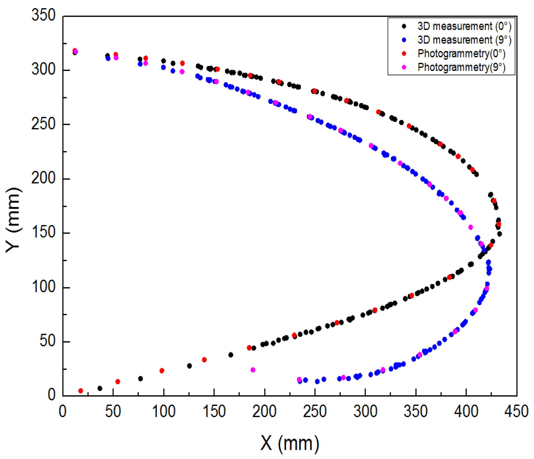
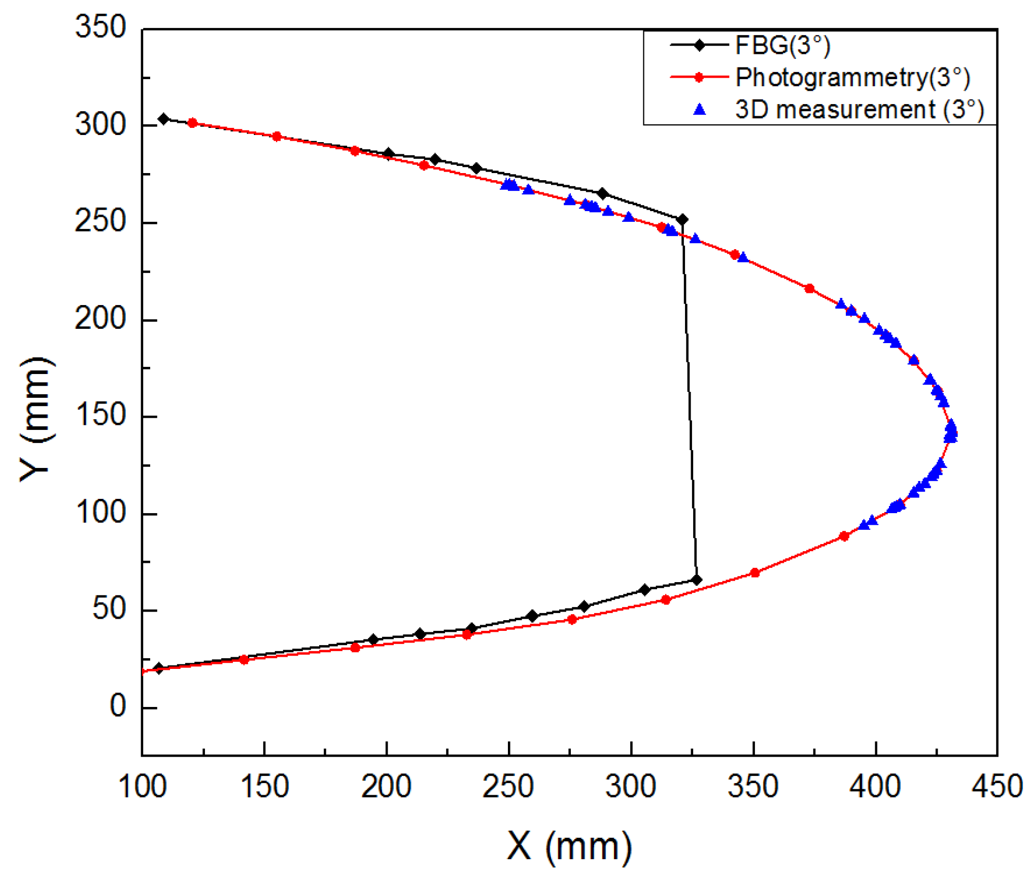
Three different measurement methods were compared and analysed. As shown in
Figure 20, the average error between the 3D scan and photogrammetric results was less than 1% when the leading edge structure was deflected downward by 0° and 9°. As shown in
Figure 21, when the leading edge structure was deflected downward by 3°, the average relative error of the FBG measurement, photogrammetry and 3D fast scan method was 8.88%. During the test, when the downward deflection angle of leading edge structure was more than 3°, the FBG sensors at the wing tip position were all ineffective. The results show that the photogrammetry and 3D scanning methods have high measurement accuracy, but are affected by the test conditions, such as light, occlusion, etc. Thus, the real-time measurement methods based on the above two methods can be further studied and applied to the test of morphing wing. The FBG method can monitor the movement process of the variable camber wing in real time, but it is affected by the sensor type, adhesive technology and data processing method for shape reconstruction. The problems such as lack of test data and measurement error caused by the above reasons need to be solved later.
5. Conclusions
The deformation process of the leading edge of full-scale variable camber wing under real flight load and drive load was accurately simulated. The test results show that the motion function and bearing capacity of the leading edge structure meet the design requirements, and the average deflection angle error is 4.59%.
A multi-point cooperative control system with precise control, fast response and stable operation was developed. The feedback results show that the control frequency of the system is as high as 1000 Hz, and the average error of applied load magnitude and direction is 0.54% and 0.24%, respectively.
The distributed sensor monitoring network was reasonably designed to ensure that the entire motion process of the leading edge can be measured and controlled. The measurement results show that the maximum error between the actual deformation and the theoretical deformation is less than 10mm, and the design target deflection angle was realised.
References
- Nie, R. Research on key technologies of morphing wing structure[D]. Doctor. Nanjing University of Aeronautics and Astronautics, 2020. [CrossRef]
- Li, X.F.; Zhang, M.J.; Wang, W.J.; et al. Research on Variable Camber Wing Technology Development [J]. Aeronautical Science & Technology, 2020, 31(02),12-24. [CrossRef]
- Ni, Y.G.; Yang, Y.; Research on the status and key technology in morphing airfoil of adaptive wings [J]. ADVANCES IN AERONATICAL SCIENCE AND ENGINEERING, 2018, 9(03), 297-308. [CrossRef]
- Leng, J.S.; Sun, J.; Liu, Y.J. application status and future[J]. Acta Aeronautica et Astronautica Sinica, 2014, 35(01), 29-45.
- He. M.; Yang. T.H.; Bai, J.Q.;, et al. Research on the drag reduction benefits of variable camber technology of civil transport jet based on trailing-edge flap deflection[J]. Acta Aeronautica et Astronautica Sinica, 2020, 41(7), 123462. [CrossRef]
- Cheng, C.X.; Li, D.C.; Xiang, J.W,et al. Analysis on aerodynamic characteristics of morphing wing with flexible trailing edge[J].Journal of Beijing University of Aeronautics and Astronautics ,2016 ,42(2), 360-367. [CrossRef]
- Schmitz, A.; Horst, P. Buckling of multiple discrete composite bundles in the elastomeric foundation of a curvature-morphing skin, Composite Structures, 2015 Volume 134, 1014-1023. [CrossRef]
- Hannig, A. Static and fatigue transverse crack initiation in thin-ply fibre-reinforced composites. 2018. ISBN 978-3-928628-97-6.
- Schmitz, A.; Horst. P. A finite element unit-cell method for homogenised mechanical properties of heterogeneous plates, Composites Part A: Applied Science and Manufacturing, 2014, Volume 61, 23-32, ISSN 1359-835X. [CrossRef]
- Wang, Z.G.; Yang, Y. Structural Design and Analysis of Compliant Skin for Morphing Wing Leading Edge [J]. Hi-Tech Fiber and Application, 2020, 45(03), 41-47.
- Zhang, P.; Zhou, L.; Qiu, T. Mechanical property analysis and structural design of flexible skin based on deformable honeycomb[J]. Chinese Journal of Solid Mechanics, 2013, 34(05), 433-440. [CrossRef]
- Yin, W. L.; Tian, D.K. Deformation of flexible skin for variable trailing-edge camber wing [J]. Journal of Nanjing University of Aeronautics & Astronautics, 2012, 44(04), 493-496. [CrossRef]
- Wang, Z. G.; Yang, Y. Optimization design of composite flexible skin for leading edge with variable camber[C].NCCM-21, Hohhot, China, 25-27 August 2020. [CrossRef]
- Zhang, Y.X.; Qiu, T.; Wang, Z.J. A flexible skin design technology and the application on variable camber trailing edge[J]. Aeronautical Science & Technology, 2012, 05, 26–28.
- Yan, F.F.; Xu, X.D. Negative poisson’s ratio honeycomb structure and its applications in structure design of morphing aircraft[J].Chinese Journal of Mechanical Engineering, 2012, 23(05): 542-546. [CrossRef]
- Vasista, S.; Nolte, F.; Monner, H.P.; Horst, P.; Burnazzi M. Three-dimensional design of a large-displacement morphing wing droop nose device. Journal of Intelligent Material Systems and Structures, 2018:1-20. [CrossRef]
- Rudenko, A.; Monner, H.; Rose, M. A Process Chain for Structural Optimization of a Smart Droop Nose for an Active Blown High Lift System. 22nd AIAA/ASME/AHS Adaptive Structures Conference, Maryland, 13-17 January 2014. [CrossRef]
- Miller, E.; William, L.; Josue, C.; et.at. Approach for structurally clearing an adaptive compliant trailing edge flap for flight. 2015.
- 19. Sui, T; Xu, Z.W. Study on Multi-motor Distributed Driving System of Morphing Wing with Flexible Skin, Mechanical Science and Technology for Aerospace Engineering. 2023, 42(09), 1551-1558. [CrossRef]
- 20. Yao, B; Cai, L.X; Bao C. Research on acquisition of mechanical properties of materials based on conical indentation[J]. Acta Aeronautica et Astronautica Sinica, 2013, 34(08), 1874-1883.
- Zhang, X.X.; Yan, B.X.; Sun, G.K.; et al. The Design of Flexible Deformation Wing and Structural Mechanical Property Analysis[J]. Machinery Design & Manufacture, 2020,(05):163-166. [CrossRef]
- Zhao, A.M; Liu. D.S; Su. Y; et al. Design and Numerical Simulation of an Innovation Overall Variable Camber Wing[J]. Aeronautical Computing Technique, 2018,48(03),111-113+121.
- Contell Asins, C.; Landersheim, V.; Laveuve, D.; Adachi, S.; May, M.; Wacker, J-D.; Decker, J. Analysis and Design of a Leading Edge with Morphing Capabilities for the Wing of a Regional Aircraft—Gapless Chord- and Camber-Increase for High-Lift Performance. Applied Sciences. 2021; 11(6),2752. [CrossRef]
- Zhang, P.; Zhou. L.; Qiu. T. Mechanical property analysis and structural design of flexible skin based on deformable honeycomb[J]. CHINESE JOURNAL OF SOLID MECHANICS, 2013, 34(05),433-440. [CrossRef]
- Liu, L.B. Mechanical analysis of trailing-adge with morphing skin[D]. Master. Harbin Institute of Technology. Harbin. 2012.
- Yang, Y.; Wang, B.W.; Lyu, S.S.; et al. Review of technical development of variable camber wing[J]. Acta Aeronautica et Astronautica Sinica. 2020. 43(01),144-163. [CrossRef]
- Rudenko, A.; Schmitz, A.; Monner, H.; Horst, P. Extremely deformable morphing leading edge: Optimization, design and structural testing. Journal of Intelligent Material Systems and Structures. 2017. 29. 1045389X1772103. [CrossRef]
- Vasista, S.; Riemenschneider, J.; Keimer, R.; Monner, H.; Nolte, F.; Horst, P. Morphing Wing Droop Nose with Large Deformation: Ground Tests and Lessons Learned. Aerospace 2019, 6, 111. [CrossRef]
- Vasista, S.; Riemenschneider, J.; Monner, H.; Nolte, F.; Horst, P. Manufacture and Testing of a Large-displacement Droop-Nose Morphing Wing Leading Edge. AIAA SciTech. 2019. [CrossRef]
- Noviello, M.C.; Pecora, R.; Amoroso, F.; Rea, F.; Arena, M.; Dimino, I. Experimental shape reconstruction of a morphing wing trailing edge in simulated operative conditions. 8th International Conference on Mechanical and Aerospace Engineering, Prague, Czech Republic, 22-25 July 2017, 249-256. [CrossRef]
- Nie, R.; Qiu, H.J.; Ji, H.L. Flexible skins theoretical and experimental research for one-dimensional wing morphing[J]. Science Technology and Engineering, 2017, 17(11),115-121.
- Chen, H.; Wang, B.F.; Lu, J.Y. et al. Shape optimization and test analysis of flexible skin for morphing wing[J]. ORDNANCE MATERIAL SCIENCE AND ENGINEERING, 2013, 36(02): 31-34. [CrossRef]
- Radespiel, R.; Heinze, W. SFB 88o: Fundamentals of high lift for future commercial aircraft. CEAS Aeronautical Journal. 2014. [CrossRef]
Figure 1.
Model of variable camber wing leading edge structure.
Figure 1.
Model of variable camber wing leading edge structure.
Figure 2.
Location of loading points.
Figure 2.
Location of loading points.
Figure 3.
Schematic diagram of follow-up loading device.
Figure 3.
Schematic diagram of follow-up loading device.
Figure 4.
Motion envelope analysis.
Figure 4.
Motion envelope analysis.
Figure 5.
Variable camber wing leading edge follow-up loading test device.
Figure 5.
Variable camber wing leading edge follow-up loading test device.
Figure 6.
Structure of slide rail.
Figure 6.
Structure of slide rail.
Figure 7.
Schematic diagram of sensor setup for test loading points.
Figure 7.
Schematic diagram of sensor setup for test loading points.
Figure 8.
Principle of multi-point cooperative closed-loop control.
Figure 8.
Principle of multi-point cooperative closed-loop control.
Figure 9.
FBG sensor attachment during test.
Figure 9.
FBG sensor attachment during test.
Figure 10.
Photogrammetric system working scenario.
Figure 10.
Photogrammetric system working scenario.
Figure 11.
Schematic diagram of 3D rapid scanning system.
Figure 11.
Schematic diagram of 3D rapid scanning system.
Figure 12.
Contrast curve of deflection angle in leading edge motion function test.
Figure 12.
Contrast curve of deflection angle in leading edge motion function test.
Figure 13.
Contrast curve of load on wing surface at leading edge strength test.
Figure 13.
Contrast curve of load on wing surface at leading edge strength test.
Figure 14.
Contrast curve of load angle between upper and lower wing surface during leading edge strength test.
Figure 14.
Contrast curve of load angle between upper and lower wing surface during leading edge strength test.
Figure 15.
Shape change curve of leading edge in motion function test (0°, 9°, 15°).
Figure 15.
Shape change curve of leading edge in motion function test (0°, 9°, 15°).
Figure 16.
Analysis of deformation accuracy of leading edge in motion function test.
Figure 16.
Analysis of deformation accuracy of leading edge in motion function test.
Figure 17.
Strain curve of wing upper surface with different deflection angle of leading edge.
Figure 17.
Strain curve of wing upper surface with different deflection angle of leading edge.
Figure 18.
Strain curve of wing lower surface with different deflection angle of leading edge.
Figure 18.
Strain curve of wing lower surface with different deflection angle of leading edge.
Figure 19.
FBG sensor arrangement.
Figure 19.
FBG sensor arrangement.
Figure 20.
contrast curve of 3D scanning and photogrammetry results (0 °, 9 °).
Figure 20.
contrast curve of 3D scanning and photogrammetry results (0 °, 9 °).
Figure 21.
FBG/3D scanning/photogrammetry results (3°).
Figure 21.
FBG/3D scanning/photogrammetry results (3°).
Table 1.
Test load of variable camber wing leading edge.
Table 1.
Test load of variable camber wing leading edge.
| Structure deflection angle(°) |
Deformation driving actuating cylinder displacement (mm) |
Wing upper surface test load (N) |
Wing lower surface test load (N) |
| 0 |
0 |
-1201.26 |
61.28 |
| 3 |
-7.306 |
-888.99 |
90.39 |
| 6 |
-14.632 |
-943.49 |
92.079 |
| 9 |
-21.960 |
-946.21 |
104.27 |
| 12 |
-29.268 |
-945.18 |
106.95 |
| 15 |
-36.353 |
-944.15 |
109.63 |
|
Disclaimer/Publisher’s Note: The statements, opinions and data contained in all publications are solely those of the individual author(s) and contributor(s) and not of MDPI and/or the editor(s). MDPI and/or the editor(s) disclaim responsibility for any injury to people or property resulting from any ideas, methods, instructions or products referred to in the content. |
© 2024 by the authors. Licensee MDPI, Basel, Switzerland. This article is an open access article distributed under the terms and conditions of the Creative Commons Attribution (CC BY) license (http://creativecommons.org/licenses/by/4.0/).
