B. Improvement in the Flow Field Environment
When the flow characteristics of the gas and its deflection effects are optimized and controlled, the near-ground flow field environment at the launch site undergoes changes, including the propagation of pressure disturbances, temperature variations, and the degree of liquid water vaporization. These changes directly impact the design of ground launch facilities and structures. This section focuses on studying the influence of the integrated dual-sided deflector system on the improvement of the gas flow field environment. By comparing and analyzing the temperature/pressure distribution characteristics of different thermal protection and cooling schemes, the superior performance of the integrated dual-sided deflector system in convective cooling, thermal protection, and improvement of the gas flow field environment can be demonstrated.
- (1)
Propagation of Pressure Disturbances
The pressure disturbances generated by the engine nozzle typically propagate through the fluid medium in the form of initial shockwaves and spread to the surrounding space. The propagation characteristics and process of these disturbances are greatly influenced by the properties of the medium and the surrounding environmental conditions.
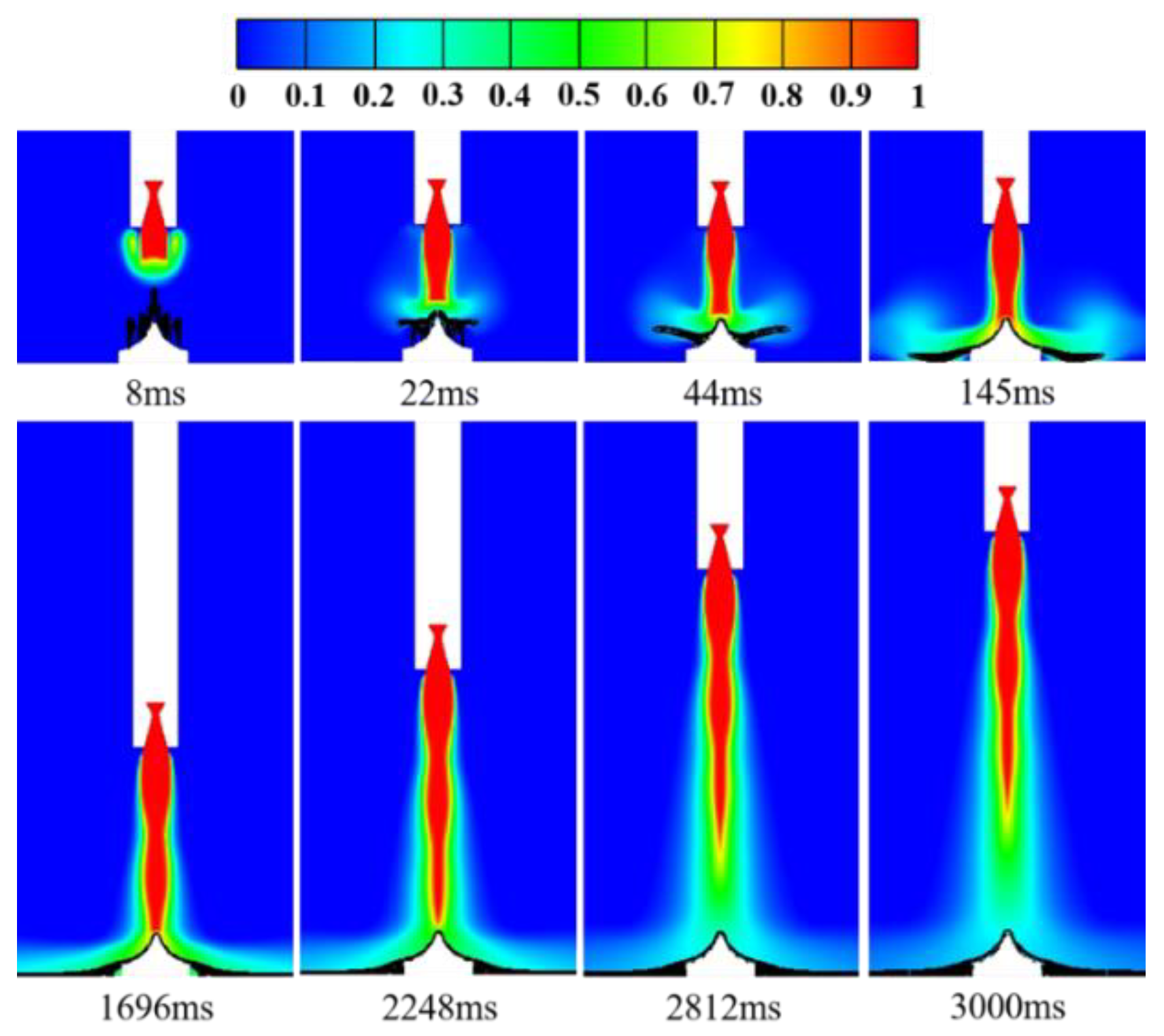
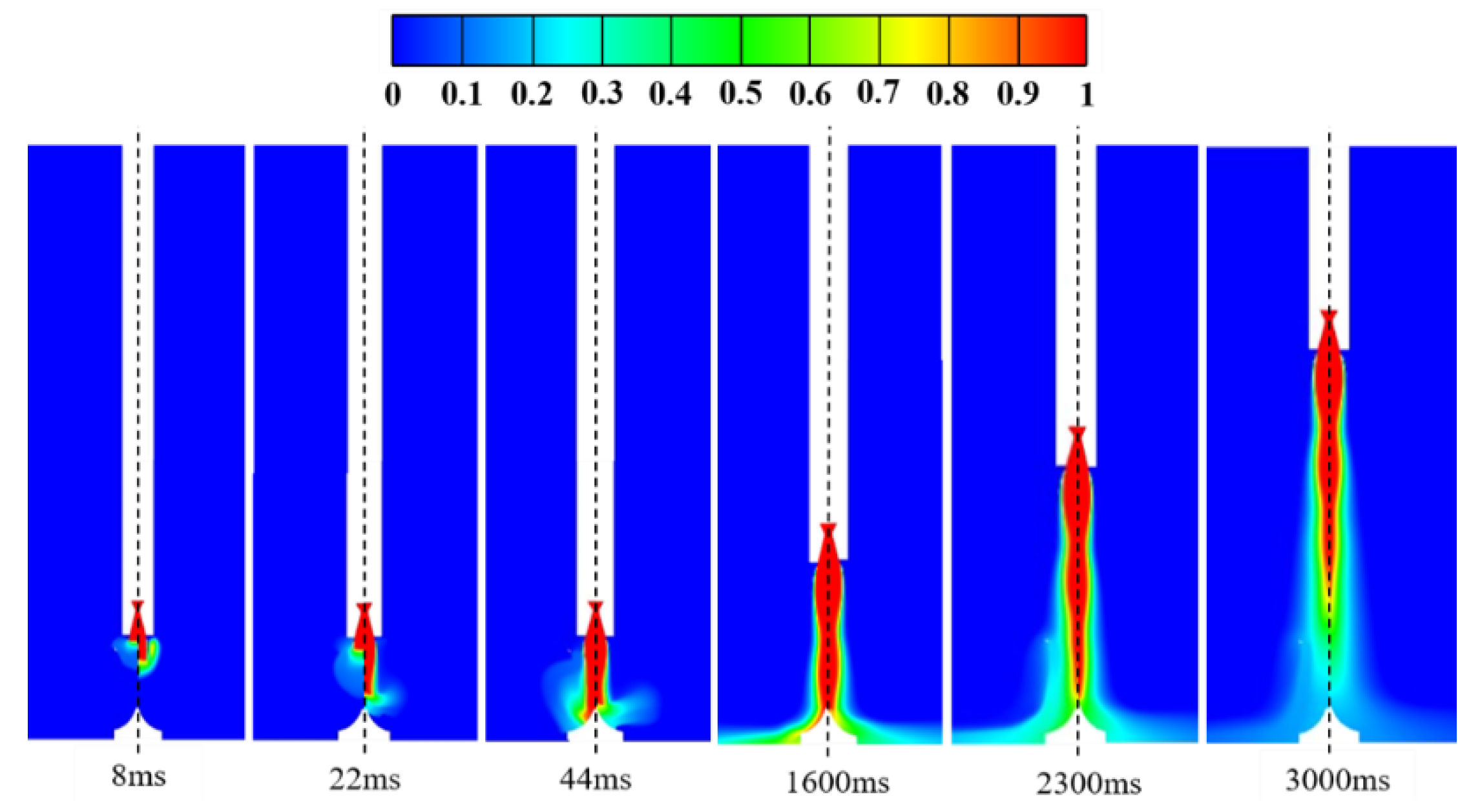
Figure 12 illustrates the pressure distribution within the flow field affected by the integrated dual-sided deflector system. From the figure, it can be observed that after the ignition of the engine, the initial shockwave interacts with the liquid water jet injected from the orifices located at the top of the deflector at an extremely high speed. The water jet is "captured" by the shockwave and vertically compressed downwards. Phenomena such as structural disruption of the water jet and localized vibration of water molecules consume a significant amount of energy from the shockwave [
36]. When the first high-pressure wave node of the gas jet reaches the top region of the deflector, the initial shockwave has propagated to a distant ground location away from the deflector, resulting in a significant weakening of the shockwave intensity. The second high-pressure wave node of the gas jet then appears and forms. At this point, the liquid water covers the top and mid-body regions of the deflector, forming a "W-shaped" distribution along the contour of the deflector. As the rocket continues to accelerate to higher altitudes, the gas jet fully develops, and there is no longer the propagation of shockwaves within the flow field. The spatial distribution of pressure at the bottom of the rocket becomes relatively uniform, and the high-pressure region at the top of the deflector disappears. At this stage, the liquid water has completely covered the surface of the deflector and the surrounding ground area.
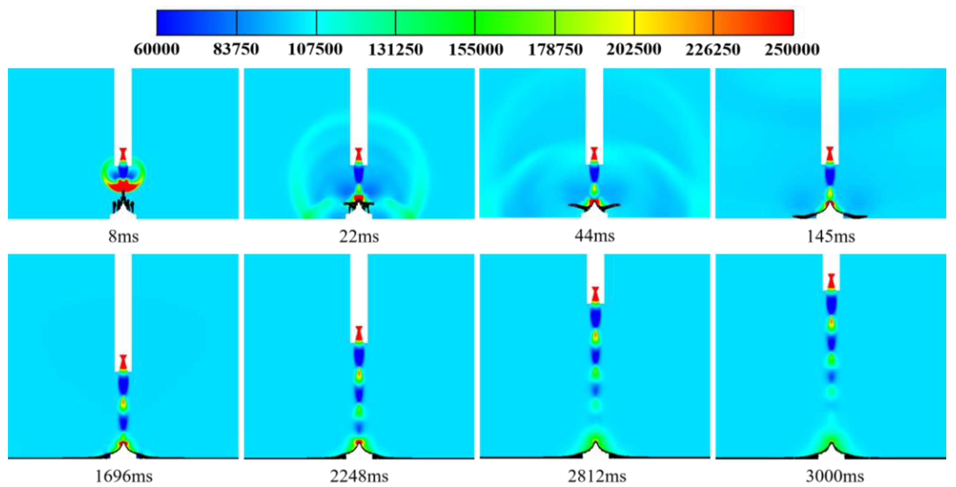
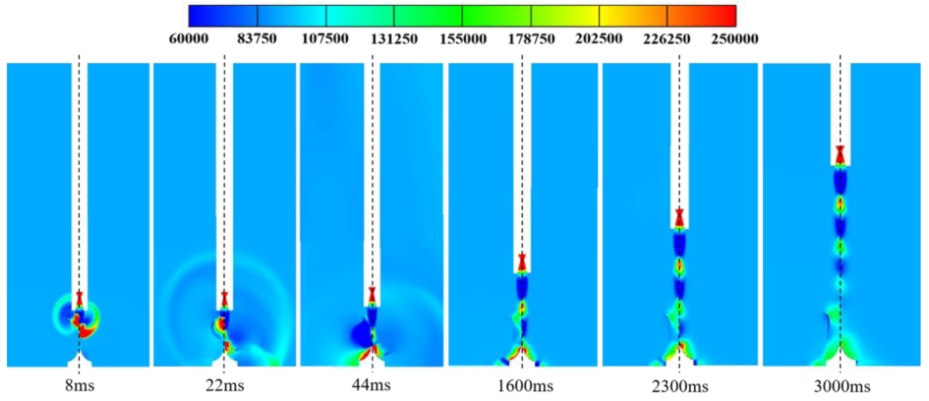
Figure 13 illustrates a typical moment of comparison between the pressure distribution of the conventional cooling system and the integrated dual-sided deflector system. From the figure, it can be observed that the conventional cooling system has a suppressing effect on the initial shockwave. The energy propagation of the shockwave is reduced, especially during the initial ignition of the engine, where the speed and intensity of the shockwave propagation are significantly delayed. As a result, the near-ground pressure environment experiences some improvement. However, a considerable area of the deflector surface is still affected by the pressure disturbances, and it remains in a high-pressure state for a prolonged period during the rocket launch. In comparison to the conventional cooling system, the integrated dual-sided deflector system exhibits a relatively weaker inhibitory effect on the propagation rate and shockwave intensity of the initial shockwave. However, the liquid water jet injected from the orifices on the deflector's surface can cover the deflector and the surrounding ground area. This provides a certain level of pressure relief protection to the deflector, significantly reducing the affected area by the pressure disturbances, primarily concentrated at the top and mid-body regions of the deflector. Additionally, when the shockwave propagates to the surface of the deflector, it disrupts the structure of the liquid water jet, causing deformation and spreading of the water jet. During this process, some of the energy of the shockwave is consumed. Furthermore, the inertia of liquid water is greater than that of gas, and the shockwave's energy is also partially consumed when it induces vibrations in the liquid water molecules through localized oscillations. The combined effect of these two mechanisms effectively weakens the dynamic load impact intensity of the shockwave on the deflector and reduces the duration and range of the pressure disturbances on the deflector surface. Therefore, the integrated dual-sided deflector system demonstrates superior improvement in terms of inhibiting the range and intensity of pressure disturbances compared to the conventional cooling system.
- (2)
Temperature Variation Process
The variation of temperature in the near-ground flow field at the launch site is highly dependent on the parameters and flow characteristics of the gas jet. When the gas jet is injected at high velocity from the rocket engine nozzle, it carries high-temperature combustion products and thermal energy [
37]. When interacting with the surrounding air and solid surfaces, it triggers complex flow phenomena, resulting in the propagation and alteration of temperature within the flow field.
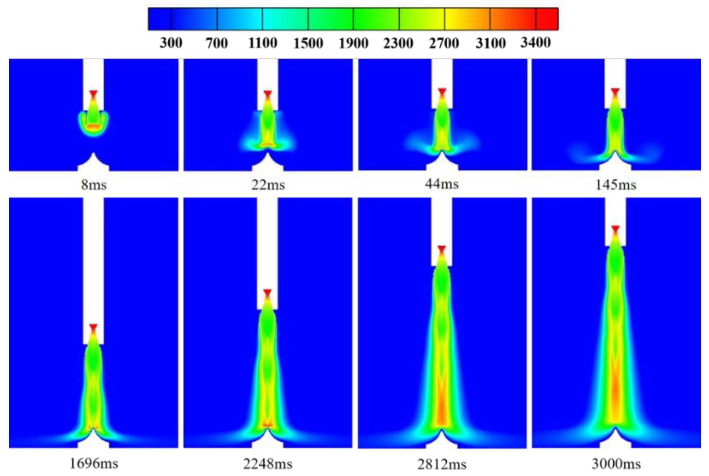
Figure 14 illustrates the temperature distribution in the
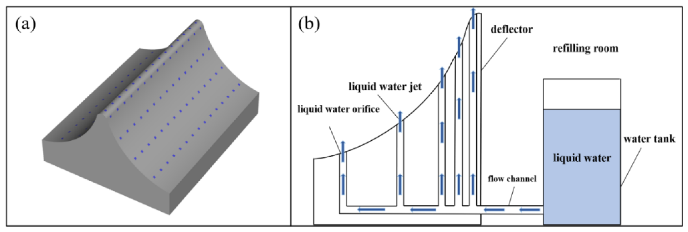
oxy-symmetric plane of the flow field affected by the integrated dual-sided deflector system. From the figure, it can be observed that throughout the entire development of the gas jet's main flow, there is no significant accumulation of high heat flux density observed on the deflector surface and its surrounding ground area. Instead, these regions remain at relatively low temperatures. The main reason for this phenomenon is the convective interaction between the downward vertical gas jet and the upward vertical liquid water jet. On one hand, the water jet is "captured" and vertically compressed by the gas jet, leading to intense momentum exchange and the dissipation of a significant amount of energy, including that of the high-temperature gas. On the other hand, the liquid water jet injected from the deflector's surface continuously undergoes compression and changes in flow direction. This gradually forms a layer of liquid water "film" on the deflector's surface and its surrounding ground area (
Figure 10), effectively isolating the high-temperature gas jet from direct contact with the deflector surface and weakening its impact on the deflector. It can be concluded that the integrated dual-sided deflector system not only significantly reduces the thermal load impact intensity of the gas jet on the deflector, but also effectively performs insulation and cooling, improving the temperature environment in the near-ground flow field.
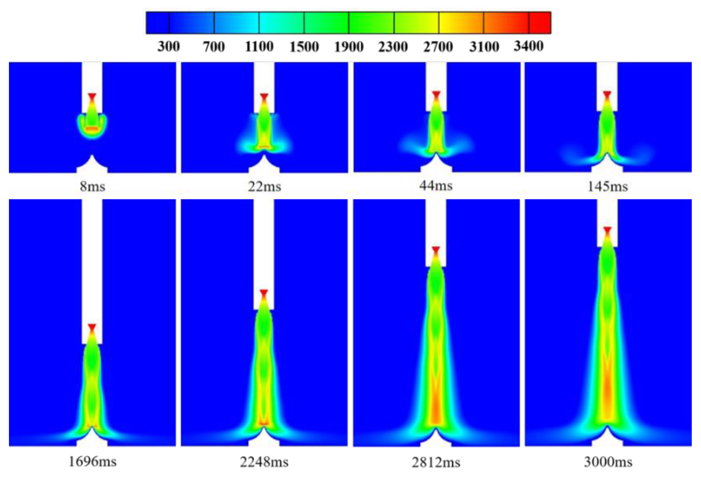
Figure 15 presents a comparison of temperature distribution in the flow field between the conventional cooling system and the integrated dual-sided deflector system. From the figure, it can be observed that the conventional cooling system restricts the diffusion of high-temperature gas into the surrounding space, significantly reducing the range of areas near the ground affected by high-temperature gas. Specifically, there are no high-temperature regions near the ground in the vicinity of the dual-sided deflector. However, the surface of the deflector, especially the top and mid-body regions, still experiences prolonged and intense thermal load impact effects. In contrast, the integrated dual-sided deflector system effectively suppresses the dynamic thermal load impact of the high-temperature gas on the deflector. The convective interaction between the liquid water jet and the gas jet forms a protective "water film" on the surface of the deflector and its surrounding ground area (
Figure 10). This directly blocks the impact of high-temperature gas, preventing the deflector surface from being enveloped by high-temperature gas and maintaining it at a lower temperature state throughout. Therefore, the integrated dual-sided deflector system demonstrates superior improvement in terms of enhancing the temperature environment in the near-ground flow field and providing active thermal protection for the deflector.
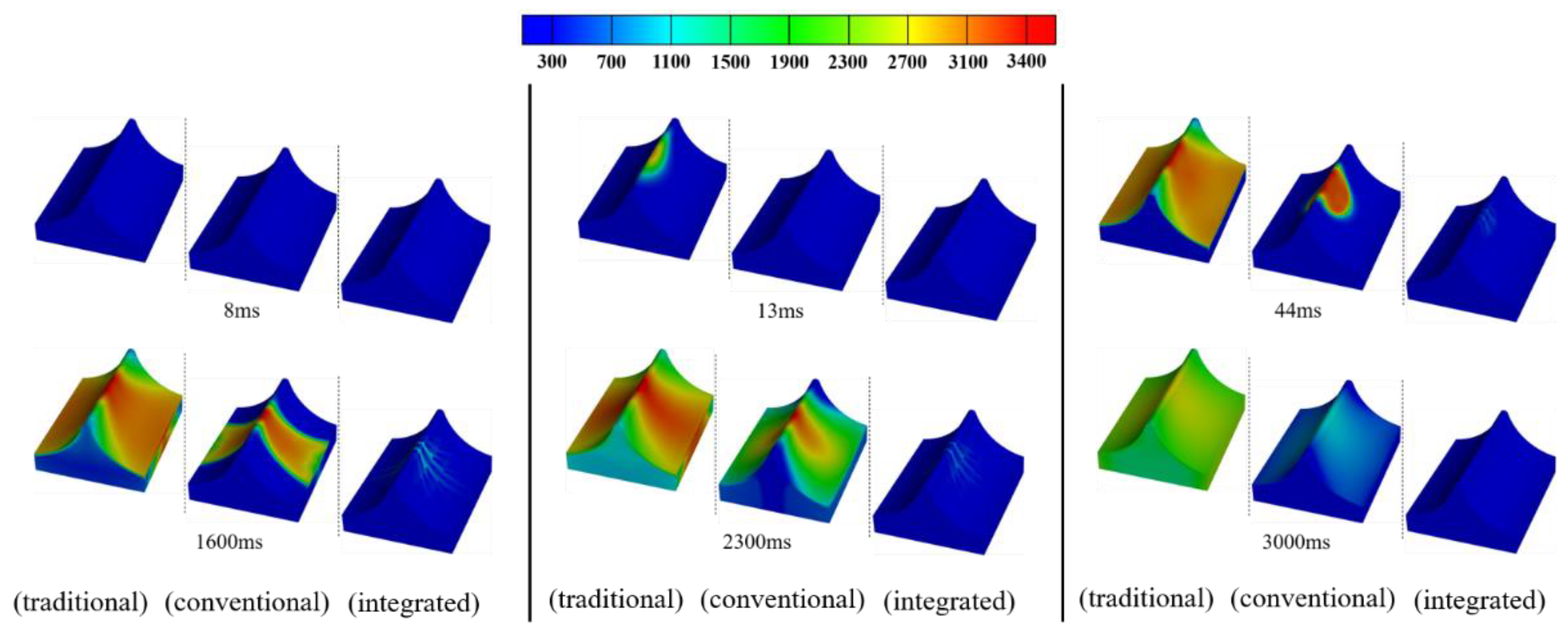
To provide a more intuitive illustration of the superior thermal protection effect of the integrated dual-sided deflector system for the deflector,
Figure 16 presents a comparison of temperature distribution maps on the deflector surface for three different scenarios. In each set of three maps corresponding to a specific moment, the leftmost map represents the traditional dual-sided deflector (traditional), the middle map represents the conventional cooling system (conventional), and the rightmost map represents the integrated dual-sided deflector system (integrated). Under the traditional dual-sided deflector, the deflector is subjected to severe thermal load impact from the gas jet during the initial stage of rocket launch. When the gas jet impacts the top of the deflector, it stagnates and forms a relatively high-temperature "core" region due to the obstruction of the top structure. Subsequently, this high-temperature "core" region spreads towards the surfaces of the deflector on both sides in an elliptical shape. At 1600 ms, high-temperature regions (2500K to 3400K) with a "hexagonal" distribution form on the surfaces of the deflector, and the temperature at the top of the deflector reaches 3400K, while the temperature in the mid-body and downstream regions is around 3000K. At 2300 ms, the high-temperature region on the deflector surface expands further, changing from a "hexagonal" shape to a "trapezoidal" shape. The temperature at the top, mid-body, downstream, and step regions of the deflector all reach 3400K. The thermal environment of the dual-sided deflector is extremely harsh. As the altitude of the launch vehicle increases, the surface temperature of the deflector gradually decreases and exhibits a more uniform distribution. However, the overall deflector still remains at high temperatures, with the highest temperature reaching close to 2100K.
Compared to the traditional dual-sided deflector, the conventional cooling system in
Figure 16 exhibits a delay of approximately 40ms in the appearance of high-temperature gas on the deflector surface. Furthermore, there is a noticeable change in the distribution of high-temperature regions on the deflector surface, transitioning from the original "hexagonal" and "trapezoidal" shapes to "quadrilateral" and "U-shaped" patterns. Additionally, due to the lateral impact and vaporization reaction of liquid water, a significant amount of energy is consumed from the high-temperature gas, reducing the impact of dynamic thermal load from the gas jet on the side edges, downstream, and step regions of the deflector. This, to some extent, improves the thermal environment on the deflector surface. However, due to the continuous impact of the gas jet core region, the regions at the top middle and mid-body of the deflector remain at high temperatures (3000K to 3400K) for a prolonged period.
In comparison to the traditional dual-sided deflector and the conventional cooling system, the integrated dual-sided deflector system effectively mitigates the intense thermal load impact from the gas jet, providing superior thermal protection for the deflector. Throughout the complete development process of the gas jet mainstream, the integrated dual-sided deflector system disperses and guides the high-temperature gas jet through the convective impact of the gas-liquid two-phase flow, reducing the concentration of high heat flux on the deflector surface. Additionally, the "water film" formed by liquid water acts as insulation for cooling, resulting in a uniform temperature distribution on the deflector surface, consistently maintaining it at a lower temperature state. This effectively prevents excessive heating of the dual-sided deflector.
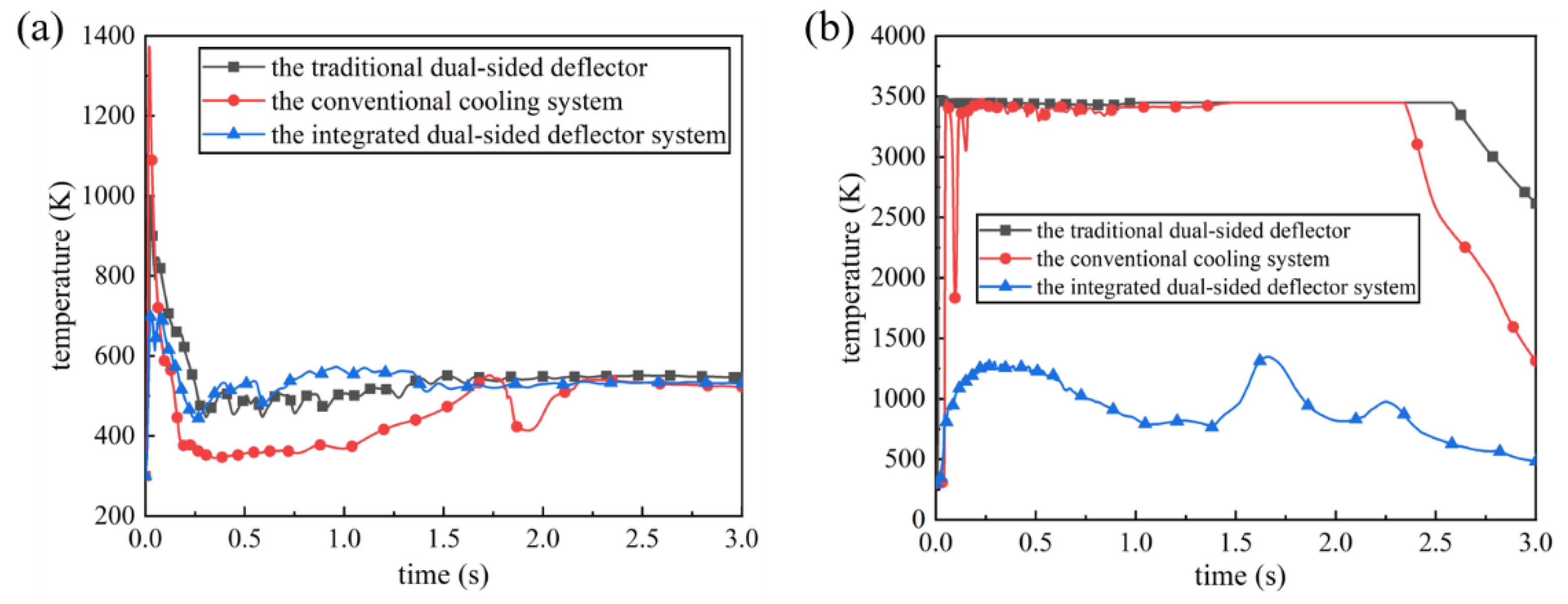
To quantitatively analyze the optimal improvement effect of the integrated dual-sided deflector system on the convective temperature environment,
Figure 17 presents the variation curves of the maximum temperatures on the bottom surface of the rocket body and the surface of the deflector over time for three different scenarios. From
Figure 17(a), it can be observed that the integrated dual-sided deflector system significantly reduces the fluctuation range of the maximum temperature curve on the bottom surface of the rocket body, delays the occurrence of the peak, and the peak value is much lower than the other two scenarios. The reason for the higher peak value in the conventional cooling system compared to the traditional dual-sided deflector is that the former has the liquid water injection nozzle located near the engine exhaust. The impact and squeezing effect of the liquid water column on the gas jet exacerbate the "rolling" phenomenon of the gas, resulting in an increase in temperature on the bottom surface of the rocket body. In the mid-stage of flow development, after the temperature curve on the bottom surface of the rocket body monotonically decreases to its minimum value, it shows a slight oscillation and upward trend. At this point, the minimum temperature value of the conventional cooling system is significantly lower than the other two scenarios, but the temperature differences among the three scenarios are not large and all remain below 580K. In the late stage of flow development, the variation curves of the maximum temperature on the bottom surface of the rocket body for all scenarios overlap and stabilize at around 530K.
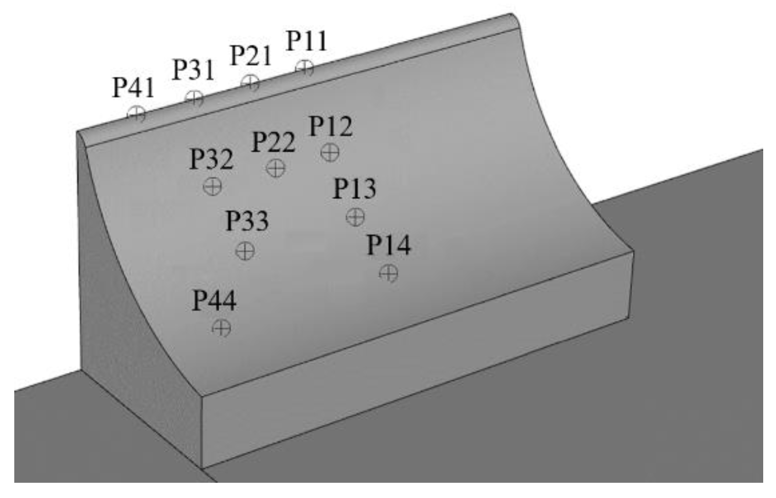
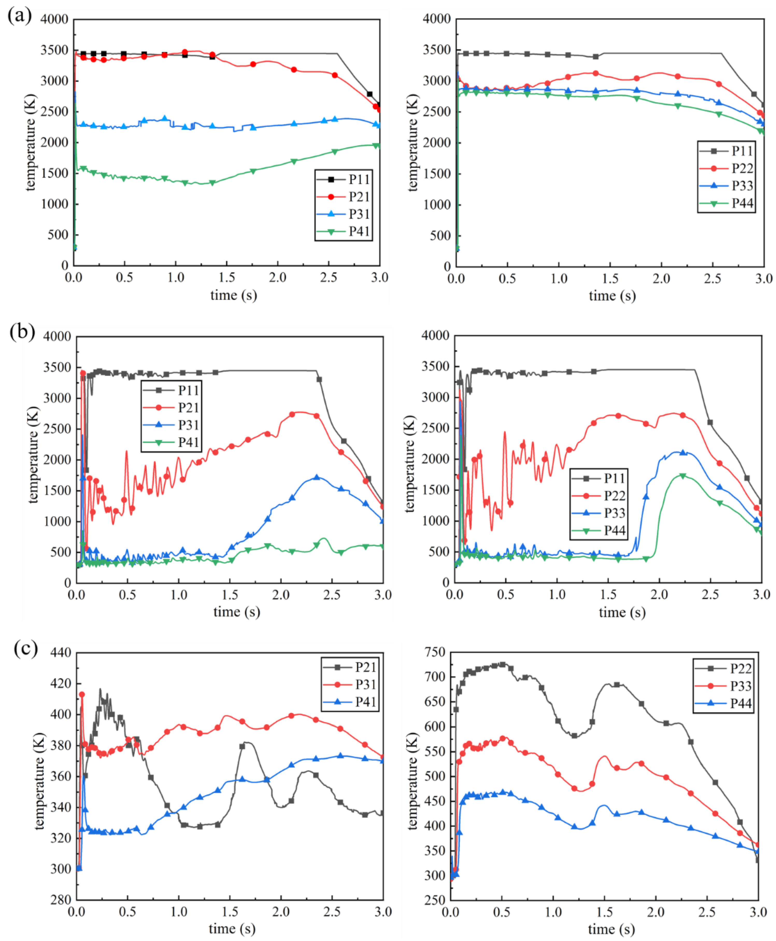
To quantitatively demonstrate the superior thermal protection provided by the integrated dual-sided deflector system for convective cooling and thermal protection of the deflector, the data of temperature variation over time for seven monitoring points P11 to P41 and P22 to P44 on the deflector surface in
Figure 6 are extracted, and the temperature curves of these points for the three different scenarios are compared as shown in
Figure 18. It should be noted that monitoring point P11, located at the liquid water injection nozzle position on the deflector surface, maintains a constant temperature value of 300K and is not plotted in
Figure 18(c). Throughout the entire development process of the gas flow field, a comparison of
Figure 18(a), (b) and (c) reveals that under the traditional dual-sided deflector, except for monitoring point P41, the temperature curves of the other monitoring points on the deflector surface remain within the range of approximately 2000K to 3400K. Under the conventional cooling system, the temperature on the deflector surface near the side edges exhibits slight oscillation and remains around 500K. The temperature curve of the deflector surface at the mid-body position fluctuates around 2000K, while the temperature near the
oxy-axisymmetric plane remains at a high temperature state of 2500K to 3400K for a prolonged period. In comparison to the other two scenarios, the temperature variation curves on the deflector surface for the integrated dual-sided deflector system show significant reduction, with none of the curves exceeding 750K. In particular, the temperature curves for monitoring points P21, P31, and P41 consistently remain below 450K. This indicates that the integrated dual-sided deflector system can more effectively optimize and regulate the temperature environment on the deflector surface. Compared to the other two scenarios, it demonstrates superior thermal protection for the deflector surface.
The peak temperature values of the temperature curves on the deflector surface for the three different scenarios in
Figure 18 are summarized and presented in
Table 3. The temperature reduction percentage of the peak values is calculated relative to the traditional dual-sided deflector (traditional), serving as the baseline. From
Table 3, it can be observed that the integrated dual-sided deflector system (integrated) exhibits a significantly greater reduction in the peak temperature values on the deflector surface compared to the conventional cooling system (conventional). The temperature reduction percentages for the former range from 76.86% to 91.29%, while the maximum reduction percentage for the latter is only 23.14%. Therefore, it can be concluded that the integrated dual-sided deflector system demonstrates superior performance in improving the temperature environment on the deflector surface.
In summary, the integrated dual-sided deflector system has a significant impact on the temperature variation process in the near-ground space of the launch site and effectively improves the temperature environment on the deflector surface. Through qualitative and quantitative comparative analysis of the thermal protection effectiveness of the deflector and its surface temperature variation curves, the superior performance of the integrated dual-sided deflector system in reducing the flow field temperature, suppressing temperature fluctuations, and providing long-lasting thermal protection has been validated. These improvements are crucial for ensuring the stability of the flow field, protecting ground launch equipment and facilities from the influence of high-temperature gases, and enhancing the operational efficiency of the ground launch system in space launch facilities.
- (3)
The degree of vaporization of liquid water
In the region exposed to high-temperature gas jet, liquid water undergoes intense vaporization, generating a large amount of water vapor. On one hand, the liquid water undergoes an endothermic phase change, consuming a significant amount of energy, including the initial shockwave and high-temperature gas. On the other hand, the generated water vapor partially dilutes the high-temperature gas, alleviating the accumulation of high heat flux density near the surface of the deflector and the surrounding ground area. During vehicle launching, the degree of vaporization of liquid water varies significantly depending on the chosen thermal protection and cooling scheme.
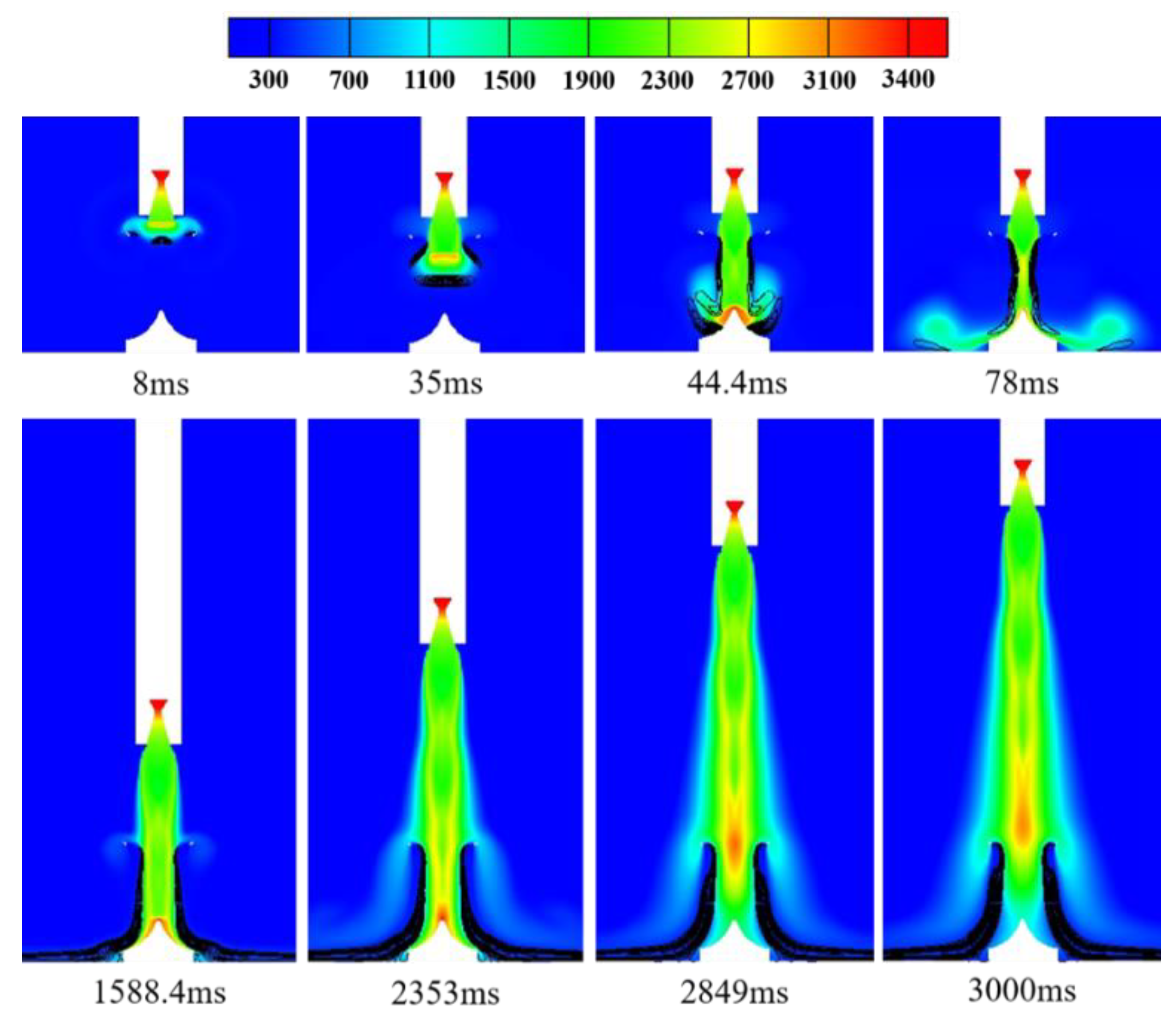
Figure 19 illustrates the distribution of liquid water vaporization phenomena within the temperature field affected by the conventional cooling system. The black contour lines in the figure represent the locations and extent of vaporization reactions of liquid water. After the high-temperature gas jet is rapidly impacted onto the liquid water column upon engine exhaust, significant vaporization reactions occur at the gas-liquid interface, with a maximum vaporization reaction rate of 0.1703 kg/(m
3·s). When the gas jets impinge on the deflector, fully covering the top surface, residual liquid water on the deflector surface undergoes vaporization reactions, with a maximum vaporization reaction rate of 0.4550 kg/(m
3·s). Subsequently, as the gas jet diffuses and flows towards the ground, the vaporization zone of liquid water exhibits an "X-shaped" distribution pattern. As the rocket continues to accelerate upward, the vaporization reaction region gradually takes on an "eight-shaped" distribution, expanding along the trajectory of the gas jet. At this stage, the maximum vaporization reaction rate of the liquid water is 1.8029 kg/(m
3·s).
Unlike the conventional cooling system, the integrated dual-sided deflector system has its water spray system located on the deflector. This results in a significant change in the location of the vaporization reaction zone of liquid water within the flow field.
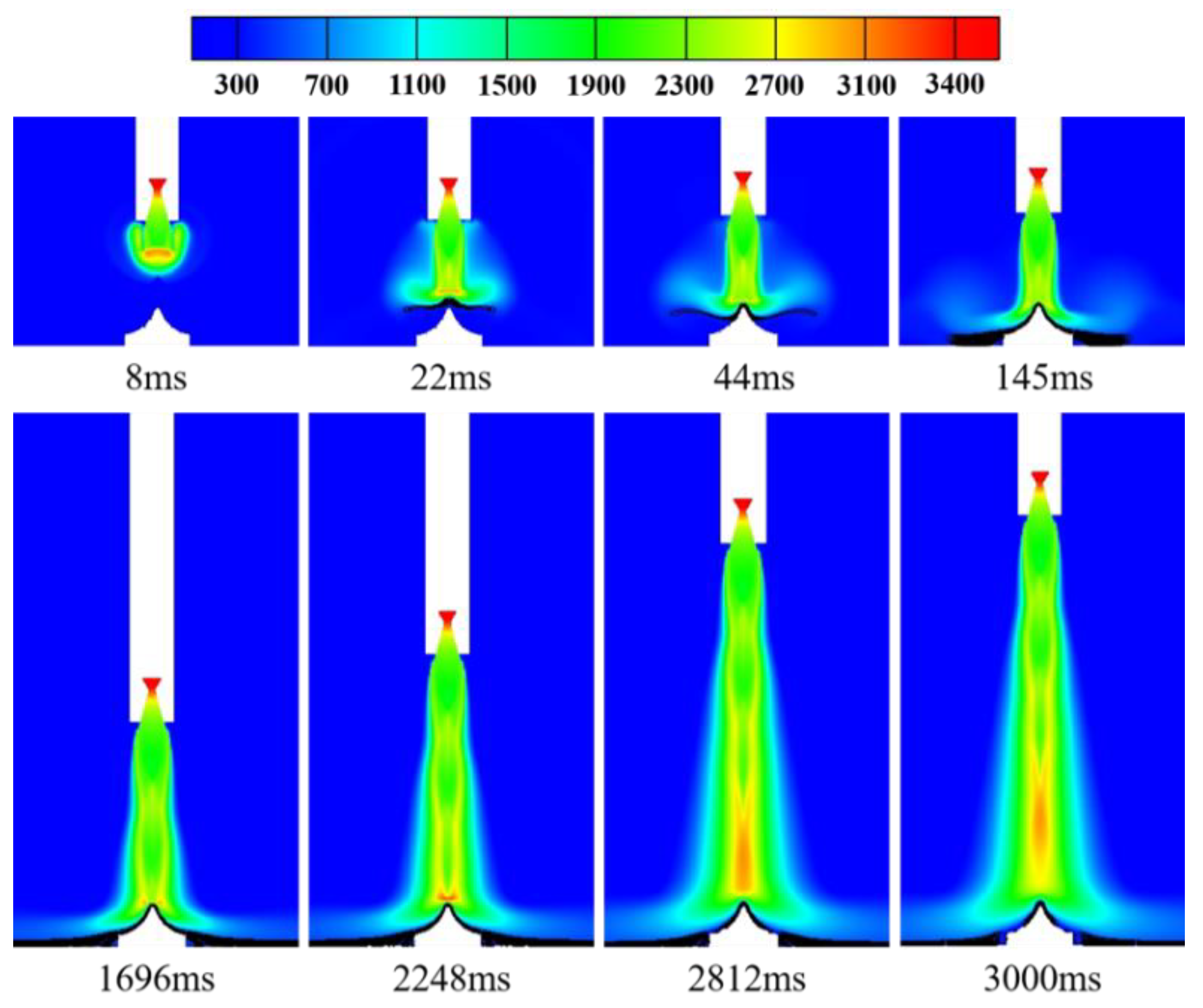
Figure 20 illustrates the distribution of liquid water vaporization phenomena within the temperature field affected by the integrated dual-sided deflector system. At the initial ignition of the engine, the high-temperature gas and liquid water move towards each other without making contact, resulting in minimal vaporization phenomena within the flow field. When the convective impact occurs between the liquid water jet and the gas jet, vaporization reactions take place at the gas-liquid interface, with a maximum vaporization reaction rate of 5.8552 kg/(m
3·s). Subsequently, as the gas jet diffuses and flows onto the surface of the deflector, the liquid water gradually covers the deflector surface. The vaporization reaction zone exhibits two different distribution patterns, namely a "W-shaped" and an "eight-shaped" distribution along the deflector's surface. The maximum vaporization reaction rate reaches 13.3604 kg/(m
3·s). When the gas flow further diffuses to the ground area away from the deflector, the liquid water has spread across the deflector surface and the surrounding ground region. The distribution range of the vaporization reaction zone expands, with a maximum vaporization reaction rate of 13.7594 kg/(m
3·s). As the rocket accelerates upward to higher positions, the gas jet core gradually moves away from the deflector, resulting in a reduction in the vaporization reaction zone of the liquid water. At this stage, the maximum vaporization reaction rate is 11.9659 kg/(m
3·s).
A comprehensive comparison between
Figure 19 and
Figure 20 reveals that the maximum vaporization reaction rate of liquid water within the flow field affected by the integrated dual-sided deflector system is significantly higher than that of the conventional cooling system. In the former case, the maximum value reaches 13.7594 kg/(m
3·s), while in the latter case, it is only 1.8029 kg/(m
3·s). This indicates that compared to the conventional cooling system, the integrated dual-sided deflector system, with the continuous injection of liquid water jet through the surface orifices of the deflector, significantly increases the contact area between the gas and liquid phases. This, in turn, enhances the degree of vaporization of liquid water within the flow field, effectively reducing the temperature and heat flux density of the flow field, and achieving optimal improvement in the flow field environment.
