Introduction
Research reactors (RR) play a vital role in producing neutrons for various applications, distinct from larger nuclear power reactors used for electricity generation. These reactors serve multiple purposes in nuclear engineering, particle physics, nuclear physics, agriculture, radiochemistry, activation analysis, material sciences, and nuclear medicine. Despite having a lower potential hazard to the public compared to power reactors, RRs demand top priority in safety to ensure the well-being of operating staff and prevent any release of radioactive fission products [
1]. Safety assessments for RRs should consider potential hazards associated with their operation. Given their diverse applications and usefulness, RRs have been constructed and are under construction in various countries.
Safety assessments are crucial for supporting licensing decisions related to plant acceptability. They involve examining all aspects of RR safety, covering normal operation, failures, and potential events that could pose risks to personnel, the public, or the environment [
2]. The deterministic safety assessment (DSA) mainly guides the safety assessment and licensing process. In newcomer countries lacking experience in performing DSA, the licensing decision can benefit from safety analyses conducted by independent assessors.
The role of independent safety assessment is to ensure that the required safety and quality levels are met, supporting the project's safe implementation. Independent assessors aid in minimizing accident risks, controlling abnormal events, and providing valuable information for reactor operation and future analyses [
3]. As mentioned earlier, this study suggests that using the IA process would be helpful to successfully conduct safety assessment for newcomer countries. IA process involves independent experts supporting the vendor/designer in system design, installation, integration, safety acceptance, decommissioning, and modification. The process includes the preparation of assessment plans, review of safety documentation, inspection of safety cases, and the preparation of assessment reports and certifications.
As part of the DSA, thermal-hydraulic system computer codes are used as simulation tools. Among these codes, the codes used for nuclear engineering design and safety analyses, whose mechanical and physical models are more realistic and based on experiments are called as the best estimate (BE) codes.
In DSA performed for RRs, BE codes are used to calculate the temperature at which nucleate boiling starts at the fuel surface (ONB temperature). In research reactors, when the temperature of the fuel cladding exceeds the ONB temperature, the coolant flow becomes unstable. The unstable flow of coolant will cause the integrity of the fuel cladding to break down and radioactive fission products from the fuel will reach the coolant.
In the past, BE codes were used in safety analyses of research reactors without conservative initial and boundary conditions uncertainty calculations. It was claimed that the uncertainties of the models were covered by conservative initial and boundary conditions. Nowadays, BE codes are used with uncertainties taken into account in order to determine safe operating margins when determining the ONB temperature.
Method of using BE codes by taking into account their uncertainties is called as the best estimate plus uncertainty (BEPU) method.
BEPU method is used for the safety analysis to study the influence of various input uncertainties on the computational results obtained with complex thermal hydraulic codes and to perform uncertainty analyses for licensing purposes [
4].
In this study, the possible roles of IA and the applicability of the BEPU method for research reactors is investigated by taking into account the input uncertainties. The investigation targeted to enhance the safety analysis performed in a newcomer country, namely Ethiopia, the country of one of the authors of this study.
The study proposes an IA methodology for the first RR projects in newcomer countries, focusing on Ethiopia. A questionnaire was distributed to nuclear industry experts to gather opinions on the applicability of IA to improve safety assessments. The study emphasizes the need for a qualified regulatory body, the potential benefits of IA, and the roles IA could play in different phases of RR projects.
The VVR-K reactor was modelled and COBRA-TF (Coolant Boiling in Rod Arrays-Two Fluid) code was used as the BE code [
5]. Ethiopia is planning to build a nuclear research reactor (RR) and has signed a contract with the Russian government. However, the type of RR has not been decided yet. Based on the conditions set by the Ethiopian Nuclear Taskforce [
6], A VVR-K type is one of the RRs designed by Russians and operated so far in foreign countries (such as in Kazakhstan).
Nuclear Technology Development and Activities in Ethiopia
Ethiopia is actively pursuing nuclear technology development, focusing on RR projects as a first step towards commercial nuclear power. The Ethiopian Multipurpose Research Reactor (EMPRR) is designed to operate at 10 MW power, utilizing low-enriched uranium fuel and providing neutron beams for research, innovation, and radioisotope production. Ethiopia aims to establish the Center of Nuclear Science and Technology (CNST) to oversee RR activities [
6]. The Ethiopian Radiation and Nuclear Authority, as the regulatory body, will play a crucial role in ensuring the safe operation of the facility. International cooperation with organizations like the International Atomic Energy Agency (IAEA) is sought to enhance safety and regulatory practices.
Study on IA process
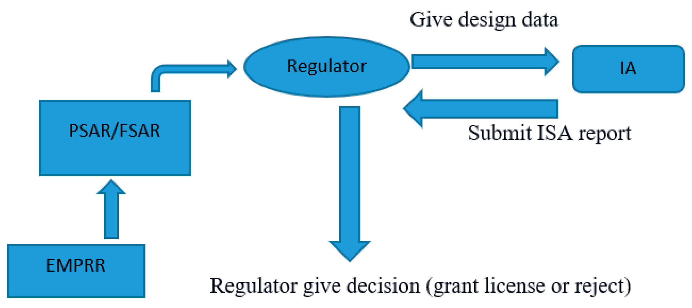
Independent assessors assess various aspects, including operator and supplier system criteria, quality and safety management systems, safety process implementation, functional and technical safety, and related safety reports. The IA process offered in this study is presented in
Figure 1.
Figure 1 shows that the regulatory body is required to perform a safety assessment of its RR before building and granting a license for the RR. So, it invites the independent assessors to carry out the safety assessment of RR designed by a designer. The independent assessor collects all information required for a safety assessment from both sides (regulator and designer or operator depending on contract), checks all basic and necessary information important for the safety of the reactor, and submits the final report of the assessment to the regulator. Based on the assessment report, the regulator makes a decision about whether to accept or reject the license. The accepted assessment that granted the license and the rejected assessment will be reported to the designer or operator for re-checking as well as to review the reason why they were rejected.
Previously, the Independent Safety Assessment has been used for the following tasks: [
7] creating an assessment plan; reviewing safety plans, safety concepts, hazards, and risk documentation; inspecting safety cases or pieces of evidence; creating assessment reports and certifications; and providing advice or lessons learned.
The evaluations completed by the impartial assessors in the past and documented in the literature are: Evaluation of the Operator's System Criteria; Evaluation of the Supplier's Quality Management System; Evaluation of the Supplier's Safety Management System; Evaluation of the Supplier's Safety Process Implementation; Evaluation of Functional and Technical Safety; Evaluation of Related Safety Reports [
7].
BEPU Method
The sources of uncertainty of a BE code fall into five general categories as shown below [
8]:
(a) Code or model uncertainties: Approximations that include only some terms in the field equations (for example, viscous stress terms are sometimes not included), uncertainties in material properties, and the assumption of fully developed flow of the system are included in this group of uncertainties.
(b) Simulation uncertainties: Uncertainties related to the discretization of the system (in other terms, uncertainties related to the representation of the nodalization or mesh cells used to obtain the system control volumes) used to obtain the control volumes represented by the field equations of the representation.
(c) Scaling uncertainty: Using data recorded in scaled experiments and relying on the laws of scale to apply data results to full-scale systems.
(d) Uncertainty of measurement and operational data: Uncertainty bands associated with boundary and initial conditions for the nuclear power plant conditions considered, e.g. core power.
(e) User influence: The variability between (i) the way various users both create and implement a system analysis code and (ii) the way they incorrectly implement the system analysis code (i.e. user errors).
An uncertainty analysis involves the identification and characterization of relevant input parameters (input uncertainty) and the methodology used to quantify the overall effect of the combination of these uncertainties on selected output parameters (output uncertainty). Different methods may handle these two key elements in different ways. In this study, the propagation of input uncertainties approach [
9] is used. In the 'propagation of input uncertainties' approach, the uncertainty is derived from the determination of 'uncertain' input parameters with certain ranges and/or probability distributions and calculations performed by varying these parameters. The propagation of input uncertainties can be performed by deterministic or probabilistic methods.
In this study, the application of the best estimation code with input uncertainties to a research reactor has been performed. Calculations were performed by varying the pressure, inlet temperature and heat generation per unit length as an input parameter (see
Table 1). This study applied the well-known statistical method called Wilks method which is standard 95% confidence and 95% probability, 93 code runs would be required, which is the number of input code runs that were performed for this study. These inputs are generated using random sampling for each the uncertain parameter showed in
Table 1.
For uncertainty calculations, the inlet pressure of the cooler was increased and decreased at 1.4 kPa intervals. This interval was determined based on a previous study [
9] which also investigated the uncertainties in the modeling of ONB.
As mentioned before, the BEPU method is also used in the licensing process of nuclear facilities. The regulatory bodies have to use logical quantifiable criteria instead of highly difficult to quantify assessments of the suitability or conservatism of a code. The fact that the calculations of BE codes are imprecise and involve uncertainty (due to the approximation of physical models and solution methods) implies that the licensing process should include appropriate uncertainty assessments. At the end of the processes, licensing is achieved by determining the conformity of the resulting BE code results with the rules and requirements set by the regulatory bodies.
Calculation of ONB temperature with COBRA-TF Code
In the calculation process of the BE code of this study, i.,e, the COBRA-TF code, the onset of nucleate boiling is calculated when the wall (i.e. fuel cladding surface) temperature is greater than the saturation temperature of the coolant and the enthalpy of the liquid film area is greater than the saturation enthalpy. Once nucleate boiling has been identified as the heat transfer regime, the Chen [
10] relation is used to find the ONB temperature in the wall-to-coolant heat transfer model. The relation can be applied to saturated bubble boiling and pressurized convection evaporation, while it can automatically switch to single-phase convection at low wall temperature and pool boiling regions at low flow rate. It also covers both extreme cases by taking into account both pressurized convection and pool boiling in wall heat transfer [
11].
Modelled Reactor
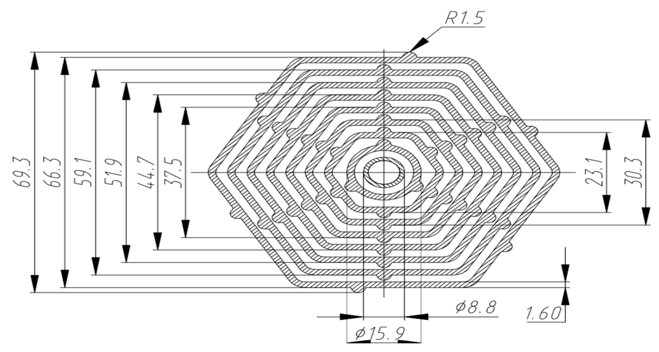
VVR-K reactors, also known as Water-Water Energetic Research Reactors, are a type of research reactor developed in Russia. These reactors are designed to produce neutron flux for various scientific and industrial purposes and have an operating power of 6 MW. The VVR-K modelled in this study was commissioned by the Republic of Kazakhstan in 1967. The VVR-K reactor has a core of low enriched nuclear fuel and water as coolant and neutron decelerator. The fuel bundle consists of eight plates of hexagonal cross-section.
The reactor vessel is housed in a cylindrical reactor vessel with a diameter of 2.3 m and a water level height of 5.3 m. Through pipelines in the bottom of the reactor vessel, cooling water is supplied to the core. The fuel elements are 1.6 mm thick and have a 0.7 mm fuel wall plus a 0.45 mm fuel cladding on both sides. The fuel is produced as a uranium dioxide- aluminum mixture, enriched with uranium-235 to 19.75%. The fuel cladding and other structural components are made of aluminum. The region between the fuels through which the coolant passes is 2 mm thick. The length of the fuel is 0.6 m.
Figure 2 shows the fuel bundle. Thermal, geometrical and material properties of the fuel and coolant are given in
Table 2.
Calculations
As mentioned before, in this study, by varying the pressure input value, inlet temperature and linear heat rate and the effect of the uncertainty in each cases in order to calculate ONB temperature for the VVR-K reactor is determined using the COBRA-TF code.
In the input file prepared for COBRA-TF, the hottest fuel plate (the third fuel element from the top in the bundle shown in
Figure 2 [
12] and the surrounding coolant channel are modelled. The inlet and outlet of this coolant channel are also defined as different channels in order to define boundary conditions.
The coolant channel containing the hottest fuel was divided into 10 volumes in the axial direction. The sensitivity of the results to number of volumes in the calculations was examined and it was decided to use 10 volumes.
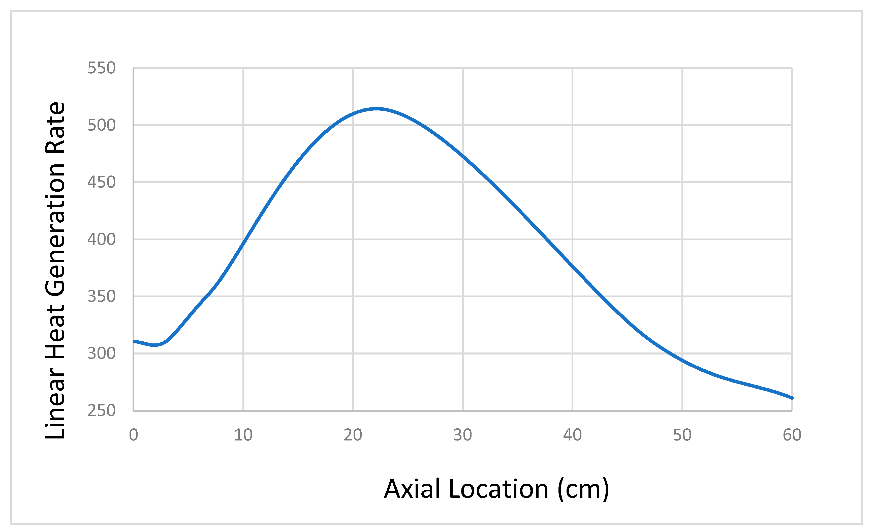
The power distribution in the axial direction for the hottest fuel was obtained by using the study by Koltochnik and Shaimerdenov. The design and operational data shown in
Table 2 is defined in appropriate places in the input file.
In the COBRA-TF model, the pressure values at the inlet and outlet of the cooling channel are entered as boundary conditions, and the outlet pressure of the channel is determined by calculating the pressure drop [
13].
The average linear power value was calculated as 6.02 kW/cm and used in the calculations.
Results
IA Case-
As above mentioned characteristics of IA present, the data related with the design of the systems are shared with the independent assessors. This means sharing the commercial data for the designer/vendor. Sharing such data would require intensive work in securing sensitive data. Sharing data, however for the research reactor design would be a bit easier since the research reactors are not widely used for the commercial purposes.
Polls and questionnaires were conducted to assess industry perspectives on the construction of new RRs, the necessity of qualified regulatory bodies, and the potential benefits of IA. The 75% of industry respondents anticipated an increase in RR construction globally, particularly in newcomer countries. Among the respondents, the 93% agreed on the need for qualified regulatory bodies in newcomer countries for RR licensing. Furthermore, 97% of respondents expressed the belief that IA would be beneficial for enhancing RR safety in newcomer countries.
Questionnaire responses from experts emphasized the importance of IA in systematically evaluating safety and quality levels throughout the RR project lifecycle. IA was seen as a valuable tool for supporting regulatory bodies during licensing, minimizing accident risks, and providing recommendations for future analyses. The roles of regulators, operators, designers, and researchers were highlighted during the IA process. International cooperation and sharing experiences were deemed essential.
BEPU Case-
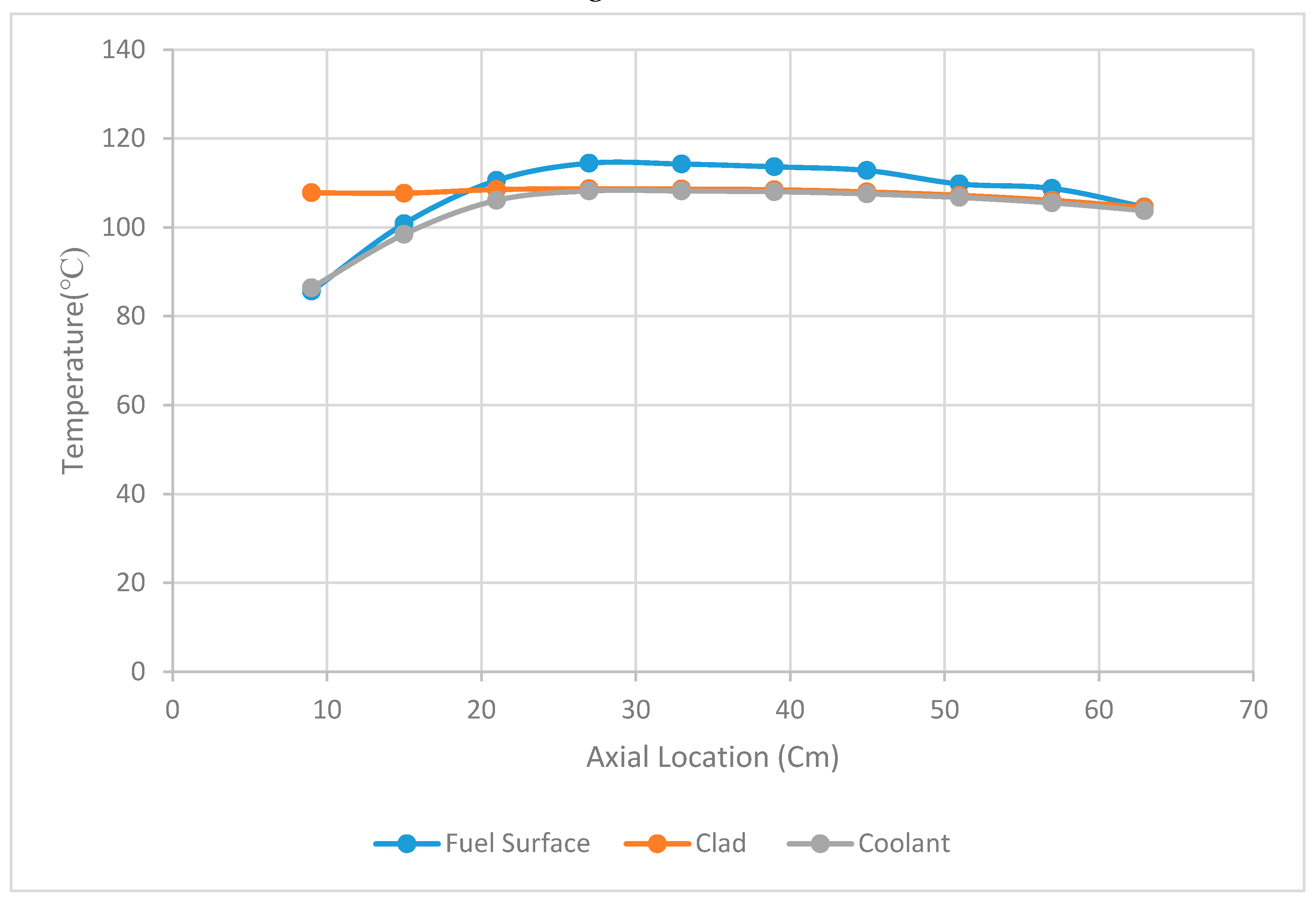
In the calculations performed with COBRA-TF, firstly the normal operating conditions (steady state) of the reactor were modelled. The steady state axial distribution of the fuel surface temperature, coolant temperature, and clad temperature is displayed in
Figure 4. Then, by increasing the heat generated in the reactor over time, the starting conditions of the ONB were determined.
As a result of the modelling of normal operating conditions, the highest temperature of the tool cladding was determined as 91.6 ◦C. This value is consistent with the 91.4 ◦C temperature given in Table-2 [
13]. This shows that the uncertainty in the COBRA-TF calculations in the normal operating model is small, considering the value taken as reference in this study. With the increase of the heat generated with time, at normal operating pressure, the ONB temperature in the axial region with the average cladding temperature was calculated as 114.44◦C. In Table-2, this value is given as 114.6 ◦C. The close agreement between the reference value and the COBRA-TF result shows that the model used in the calculation of the reference value and the Chen relation used by COBRA-TF are compatible.
In
Table 4, the simple correlation matrix (Pearson's correlation) is directly calculated from the input and output values. The positive sign means if input increases then the response also increases and vice versa. The inlet pressure has the positive correlation with the ONB temperature occurrences for σ=±1%.
In table 5, the rank correlations between the parameters of the input (fuel surface temperature, linear heat generation rate, and inlet/initial pressure) and output are listed. It displays the relative importance of each uncertain input parameter in relation to the central rod surface temperature that has been estimated. The rank for these uncertain parameters are performed based on the average correlation coefficient of each measurement, which varies slightly depending on the axial location. Ranks are determined by replacing the ranks with the original data which are obtained by the ordering data in ascending order.
As it is expected that, as the pressure decreases, the boiling temperature decreases and as the pressure increases, boiling starts at higher temperatures. Likewise as the temperature decreases by 1% and heat generation per unit length is decreases by 1% no boiling occurs. Although the result of the calculations using COBRA-TF is in accordance with this expectation, it is seen that a change of about ±1% in the inlet pressure, inlet temperature and heat generation rate per unit length causes significant deviations in the ONB temperature and even no nucleate boiling during the simulation process.
Conclusions
This comprehensive study serves as a valuable contribution to the discourse on research reactor safety, advocating for the systematic inclusion of independent assessments, robust regulatory frameworks, and meticulous uncertainty analyses in nuclear projects, especially in newcomer countries.
In this study, it is highlighted that the safety of research reactors is very important, requiring systematic safety assessments and independent evaluations. IA emerges as a crucial component to enhance safety and support the licensing process, particularly in newcomer countries. The study showed that, IA is identified as an early requirement in nuclear reactor safety, involving independent assessors who verify safety and quality levels throughout the RR project.
The BEPU calculations showed that the COBRA-TF code can be used to calculate the BEPU method and to represent uncertainties due to input uncertainties when calculating the ONB temperature for the VVR-K research reactor.
References
- IAEA Nuclear Energy Series, Application of Research Reactors. No.NP-T-5.3, Vienna 2014.
- IAEA Safety Standards for Protecting people and Environment; Safety Assessment for Research Reactors, SSG-20, Vienna, 2012.
- D’Auria, F.; Glaeser, H.; Debrecin, N. Independent assessment for new nuclear reactor safety. EPJ Nuclear Sciences & Technologies 2017, 3, 31. [Google Scholar] [CrossRef]
- Adu, S.; Horvatovic, I.; Darko, E.; Emi-Reynolds, G.; D’auria, F. Application of best estimate plus uncertainty in review of research reactor safety analysis. Nuclear Technology and Radiation Protection 2015, 30, 75–82. [Google Scholar] [CrossRef]
- Sule Ergun, Modeling of dispersed flow film boiling with two flow, five field Eulerian-Eulerian approach and effects of spacer grids on heat transfer - ProQuest. (n.d.). https://www.proquest.com/docview/305248626.
- Ethiopian National Nuclear Technology Taskforce; Pre-Project Assessment Report, Ministry of Technology and Innovation, 2019.
- Peter Wigger, Independent Safety Assessment-Benefits and Methodology.3361-3370, Procedia Social and Behavioral Science. 2012.
- Best Estimate Safety Analysis for Nuclear Power Plants: Uncertainty Evaluation, IAEA, Safety Reports Series No 52, 2008.
- Salko, R.K.; Avramova, M.N. Uncertainty analysis of sub-channel code calculated ONB wall superheat in rod bundle experiments using the GRS methodology, Progress in Nuclear Energy, Volume 65, May 2013, Pages 42-49.
- Chen, J.C. A Correlation for Boiling Heat Transfer to Saturated Fluids in Convective Flow. Process Design and Development 1967, 5, 322–327. [Google Scholar] [CrossRef]
- Sun, K.H.; Gonzalez, J.M.; Tien, C.L. Calculations of Combined Radiation and Convection Heat Transfer in Rod Bundles Under Emergency Cooling Conditions", ASME Publications, 1975.
- F. Arinkin, "SAR Descriptive Sections", Deliverable 15.2 under ANL-issued Work Order 7J-00141-0015, Institute of Nuclear Physics, Almaty, Kazakhstan, Kazakhstan, June 2014.
- Koltochnik, S.N.; Shaimerdenov, A.A. Safety analysis for the WWR-K research reactor converted to LEU Fuel 2019, 3, 204–218.
|
Disclaimer/Publisher’s Note: The statements, opinions and data contained in all publications are solely those of the individual author(s) and contributor(s) and not of MDPI and/or the editor(s). MDPI and/or the editor(s) disclaim responsibility for any injury to people or property resulting from any ideas, methods, instructions or products referred to in the content. |
© 2024 by the authors. Licensee MDPI, Basel, Switzerland. This article is an open access article distributed under the terms and conditions of the Creative Commons Attribution (CC BY) license (http://creativecommons.org/licenses/by/4.0/).


