1. Introduction
Characterization, modelling and simulation of flow in underground reservoirs are generally challenging tasks, while it becomes more complicated when dealing with naturally fractured carbonates. Well logging and laboratory measurements on core plugs are commonly utilized for characterizing both sandstone and carbonate reservoirs, where special measurements and analysis like borehole imaging, large-scale core experiments, well testing and permanent well monitoring become crucial when dealing with fractured carbonate reservoirs. The fractured reservoirs were comprehensively studied in the context of hydrocarbon production and specific approaches for reservoir characterization, modelling and flow simulation for such reservoirs have been developed and applied in the industry for decades (Barenblatt, Zheltov, & Kochina, 1960), (Warren & Root, 1963), (van Golf-Racht, 1982), (Bourdet, Ayoub, & Pirard, 1989), (Bourbiaux, Basquet, Cacas, Daniel, & Sarda, 2002), (Kuchuk, Biryukov, & Fitzpatrick, 2015).
When considering geological CO2 storage in subsurface reservoirs, including depleted oil fields, evaluation of geochemical (Machado, Delshad, & Sepehrnoori, 2023, s. 12) and geomechanical (Bohloli, et al., 2014) effects become crucial since the reservoirs rocks are exposed to new fluid (CO2) and conditions (pressure build-up) usually beyond previous operational conditions. Hydraulic properties of naturally fractured reservoirs may be sensitive to pressure changes, since these cause effective stress changes influencing fracture aperture and conductivity (Fjær, Holt, Horsrud, & Raaen, 2008) with many observations for fractured reservoirs from laboratory experiments (Bandis, S.C.; Lumsden, A.C.; Barton, N.R., 1983) and field data (Shchipanov A. , Kollbotn, Surguchev, & Thomas, 2010), (Shchipanov, Kollbotn, & Prosvirnov, 2017). There are examples of large-scale projects of CO2 storage in naturally fractured carbonates, where the In Salah storage project is very well documented in the literature (Iding & Ringrose, 2010), (Ringrose P.S., 2013), (Bohloli, Ringrose, Grande, & Nazarian, 2017). According to the literature, the following specific features of CO2 injection in the fractured reservoir may be highlighted: (1) dominating fracture flow for CO2 injected; (2) potential uplift of cap-rocks due to reservoir pressure build-up and (3) increase of hydraulic properties of the fracture rocks.
Potential of CO2 storage in a depleted oil field in the Czech Republic was previously studied for a sandstone reservoir (Berenblyum, et al., 2017) and is extended for a naturally fractured reservoir in the current study within the CO2-SPICER project (Hladik, et al., 2022). The project focuses mainly on a preparatory work for the pilot itself and developing a roadmap for potential CCS projects in the region, but not concentrating on technical evaluations of long-term large-scale CO2 storage. Overall, the project aimed at evaluating and demonstrating the CCS technology to local, national and regional stakeholders, including regulators and competent authorities. Here, getting practical experience with a real site assessment, preparation, design of facilities and CO2 handling necessary for a pilot CO2 injection are crucial for paving the way for deployment of this new technology having large potential for mitigating the climate change observed these days. Another objective of the project was to identify knowledge gaps and additional studies needed to fill this gaps prior the pilot. Choosing a mature petroleum field for the CO2 pilot has many advantages including (1) ability to utilize existing wells, (2) infrastructure (well sites, roads), (3) surface facilities and (4) benefit from available subsurface knowledge already gained during development of the field. Therefore, using an oil field at final production phase seems to be a logical choice in comparison with a deep saline aquifer, where limited data, knowledge and facilities are usually available. As an additional option, we could mention that the remaining gas volume in the gas cap of the field in focus may be considered as a potential source of “blue hydrogen” production, where by-product CO2 may be stored in the same reservoir, where from the gas is produced.
This paper focuses on describing an integrated approach that was employed to improve reservoir and fluid flow descriptions in the reservoir simulations to be capable of evaluating pilot CO2 injection for the chosen site. Injecting CO2 has specific features, which are not covered when studying a producing petroleum reservoir. This may include additional studies on geochemistry effects such as CO2-rock interactions and salt precipitation; on geomechanics, to assess CO2 impact of geomechanical parameters and impact of pressure build-up on reservoir and cap-rocks deformations; and other studies depending on scope and scale of CO2 injection project. Since pilot injection is in the focus of this study, we limited our scope by studying specific effects crucial for the pilot performance, such as evaluating safe injection envelope allowing natural fracture opening, but preventing induced fracturing and potential impact of geochemistry effects on the well injectivity related to salt precipitation. Fracture characterization was also given focus since the natural fractures govern reservoir flow capacity and the pilot performance as well.
The paper is structured in the following way:
Section 2 outlines the integrated approach used for preparing and carrying out reservoir simulations including history matching the reservoir flow model and simulation of pilot CO
2 injection.
Section 3 describes application of this integrated approach to the site in focus with results contributing to assembling of the reservoir model and matching it to the hydrocarbon production history to ensure proper reservoir description. The section completes with simulation results for the CO
2 injection pilot.
Section 4 discusses the applicability and limitations of our analysis in combination with knowledge gaps and additional studies to fill in these gaps, where the study conclusions are presented in section 5.
2. An integrated Approach to Reservoir Simulations of Pilot CO2 Injection
In this section, an integrated approach for reservoir simulations is introduced combining (1) capturing the main features of fluid flow in the fractured carbonate reservoir in focus from (1.1) geological modelling through (1.2) Dynamic Data Analysis (DDA) to (1.3) history matching at the first stage towards (2) simulating pilot CO
2 injection at the second stage.
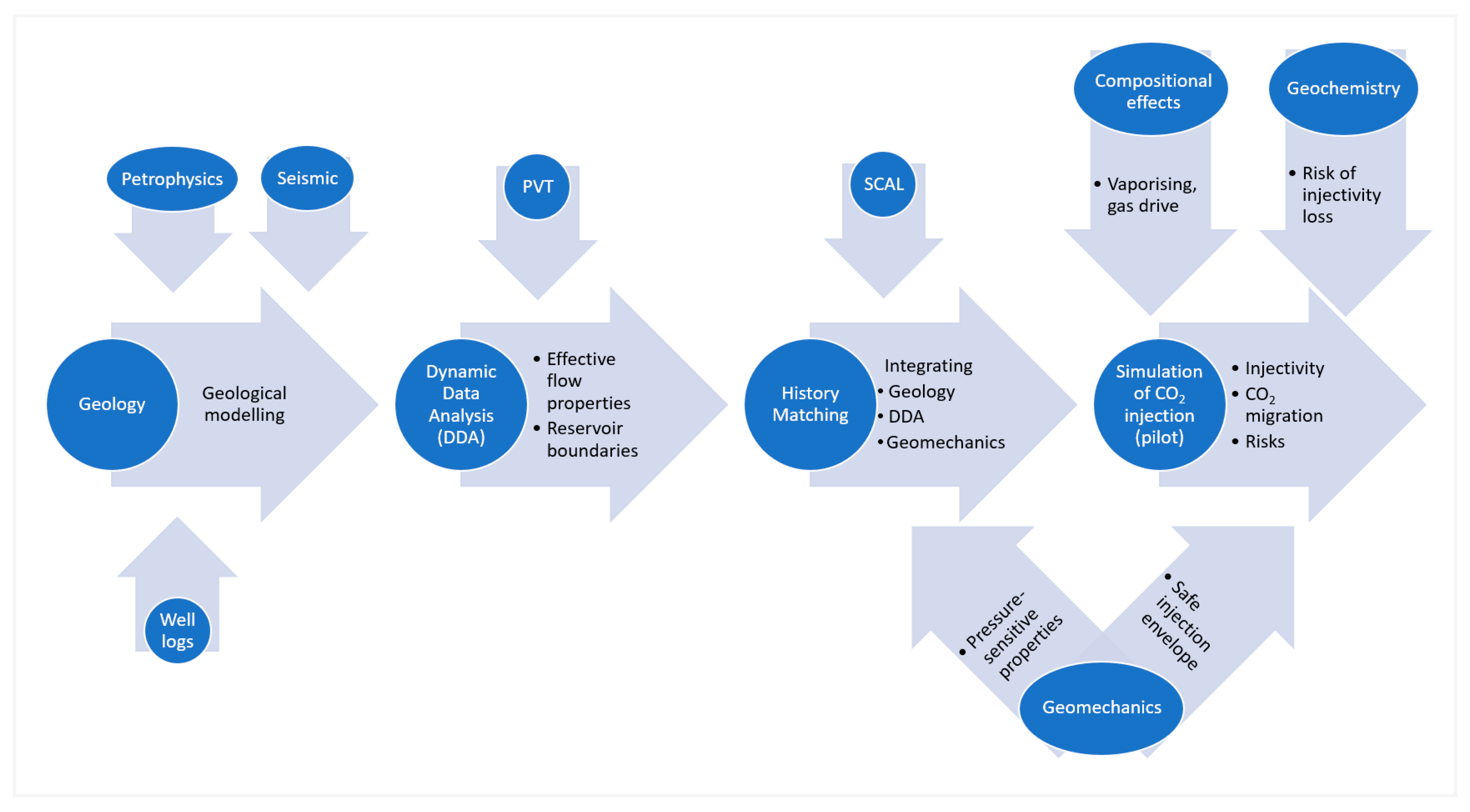
Figure 1 represents schematics of the integrated approach combining these two stages. Different sub-components of the integrated approach provide contributions at different or both stages including ‘Petrophysics’, ‘Seismic’, ‘Well logs’, ‘PVT’, ‘SCAL’ (the first stage), ‘Compositional effects’ and ‘Geochemistry’ (the second stage) and ‘Geomechanics’ (both stages).
The first stage includes conventional steps of assembling and matching a three-dimensional (3D) model of a fractured reservoir as commonly done in the oil and gas industry. Here, the geological model integrates petrophysical, seismic and well logging data (Hladik, et al., 2022). Laboratory experiments with the reservoir fluids resulted in estimating their PVT properties further employed in the dynamic data analysis (DDA) carried out to estimate the effective hydraulic properties of the fractured reservoir and reservoir boundaries, i.e., the extent of the reservoir storage complex and how it is hydraulically connected to an aquifer. Understanding of boundary conditions and the reservoir volume may be gained from the pressure dynamics during production, which will condition following CO2 injection. Integrating results of the special core analysis (SCAL) representing the multiphase flow mechanics dictated by wettability, capillary effects, and finally relative permeabilities, helps to describe and match the multiphase flow in the 3D reservoir model to the observed oil, gas and water production and pressure dynamic history. Results of the geomechanical experiments contribute to the reservoir simulations with pressure dependent functions of reservoir porosity and permeability.
This integrated approach enabled the team to develop a sufficient understanding of the reservoir complex to make credible estimates of the future CO2 injection. The CO2 simulations include additional information on compositional effects of the fluid phases as well as geochemical effects (like potential salt precipitation). Geomechanics contributes at this stage with safe injection envelope that enables the operator to develop a low-risk injection scenario. This envelope describes pressures and temperatures, where opening of existing fractures is expected, followed by possibility of tensile (induced fracturing) and shear failures (e.g. fault reactivation). This injection scenarios, i.e., how much CO2 may the reservoir take and at what rate within the injection pressure limitations, are fundamental to the whole value chain evaluation. For example, these scenarios help to evaluate capacity of transportation systems to be developed and to assess which capture projects should be developed in the region to provide sufficient CO2 volumes for such scenarios.
The next sections of this paper describe how this integrated approach has been applied to the reservoir in focus with most attention paid to the components marked by large arrows in
Figure 1 in order to create a robust description of the fractured reservoir (such as DDA, history match and geomechanics) and carry out reliable CO
2 injection simulation (such as compositional effects, geochemistry and geomechanics again). The conventional components indicated with small arrows (petrophysics, seismic, well logs, PVT and SCAL) are given less focus in the paper to limit its size.
Figure 1.
Workflow of the integrated approach.
Figure 1.
Workflow of the integrated approach.
3. Application of the Integrated Approach to a Depleted Fractured Oil Field
The integrated approach illustrated in
Figure 1 has been tested via application to the field in focus, where a multi-disciplinary team was working combining different approaches and studies including laboratory experiments and their interpretations, field data analysis and finally 3D reservoir modelling and simulations. Accounting for the study objectives, human and financial resources available and the study duration, the one-model-realization approach to geological modelling and reservoir simulations has been chosen in contrast to the ensemble-based approach with multiple model realizations currently used in the industry. Although the one-realization approach does not allow for accounting and propagating throughout simulation forecast the uncertainties resulted from well and field data interpretation and modelling, obviously present in studying such complicated reservoir setting, it enables a time-effective testing of the integrated approach in the context of preparation for the pilot CO
2 injection. Results of such testing may be useful beyond evaluation of the geological setting in focus, since combination of different components of the approach is of interest in itself and is one of the major objectives of this study. The following sections provide a short description of the study following the workflow in
Figure 1.
3.1. Geological Modelling as Conventional Basis for Reservoir Simulations
The field in focus is located 30 km South-East from Brno in the Southern Moravia in the South-Eastern part of the Czech Republic. It was discovered in 2001 at depths from 1565 to 1872 m. The field was producing with four vertical and four horizontal production wells. The field had a large gas cap on top of oil zone with a limited saline aquifer connected. The most of oil and a significant volume of initial gas reserves were produced by 2023 and the field is approaching end phase of the hydrocarbon production.
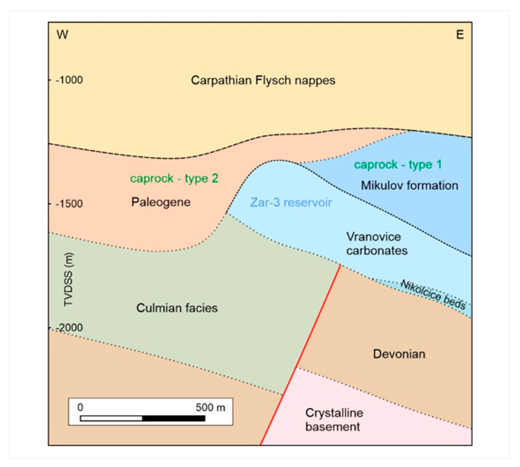
The producing reservoir is situated in a complex geological setting where the basement is formed by Precambrian age crystalline rocks, directly overlain by the Palaeozoic depositional system of Cambrian to Carboniferous age. The reservoir is formed mostly by the Vranovice Limestone and Nikolčice Formation with an overall thickness of up to 300 m. Both Mikulov Marl and the Paleogene pelites are forming the main sealing (
Figure 2).
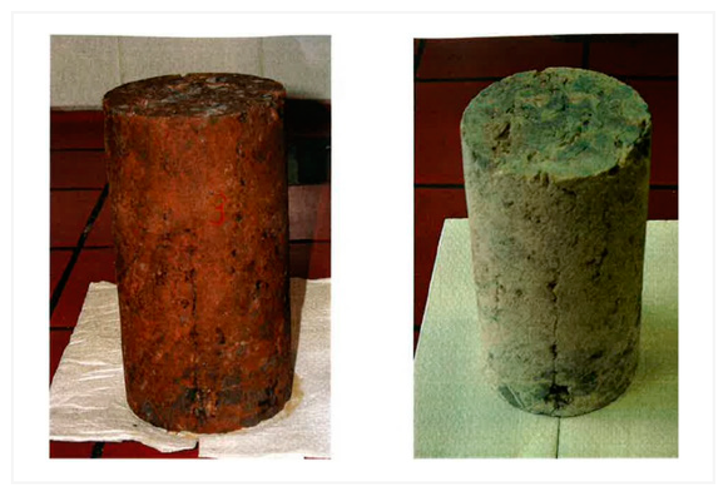
The Vranovice formation (depicted in
Figure 3) is formed by naturally fractured carbonate rocks. The petrology and geochemistry of the storage complex were studied and described in (Francu, et al., 2024). The gas cap reached initially thickness up to 150 m, and the original oil zone was approximately 105 m thick. Gas-Oil- and Oil-Water Contacts (GOC and OWC) at depths of 1490 and 1595 m were estimated based on well logging data and drill-stem tests. Both contacts are being periodically updated during production by logging in the observation well.
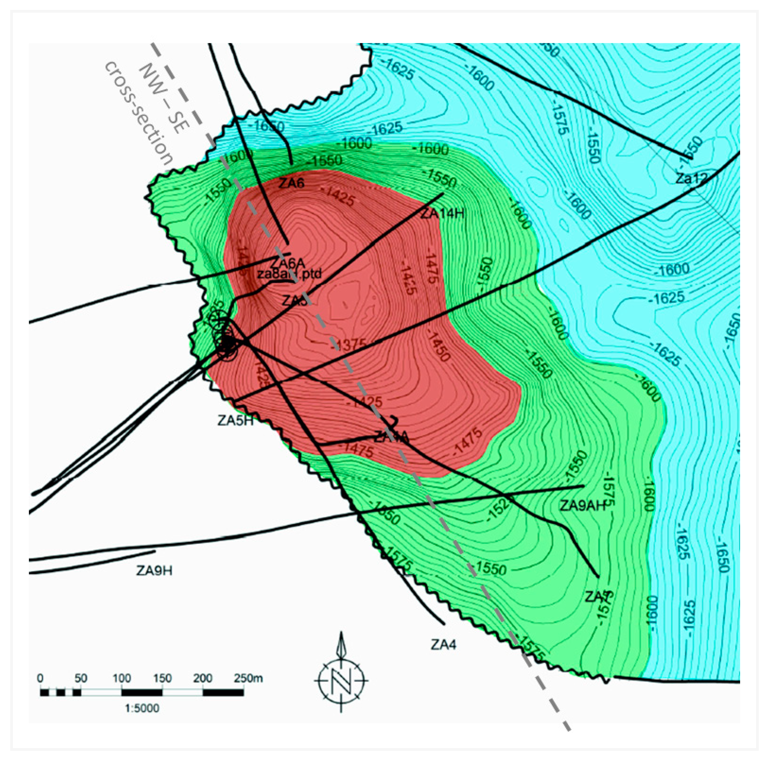
The 3D structural model served as the basis for geological modelling and further reservoir simulations. The 3D geological model, including its lithostratigraphic units, is based on seismic interpretation and fluid constituency data from wells test results, and was assembled using the Petrel software. The geological modelling and property distributions were carried out based on interpretations of the well logging data including gamma ray, spontaneous potential, resistivity, neutron, density and sonic logs. These interpretations were complemented by the calliper logs and NMR (nuclear magnetic resonance) data when available. The 3D geological model assembled covers an area larger than the reservoir itself, including an aquifer zone and the cap-rocks accounting for potential use of the model in future studies. The reservoir part of the geological model is shown in
Figure 4, describing also the fluid constituency and the well trajectories.
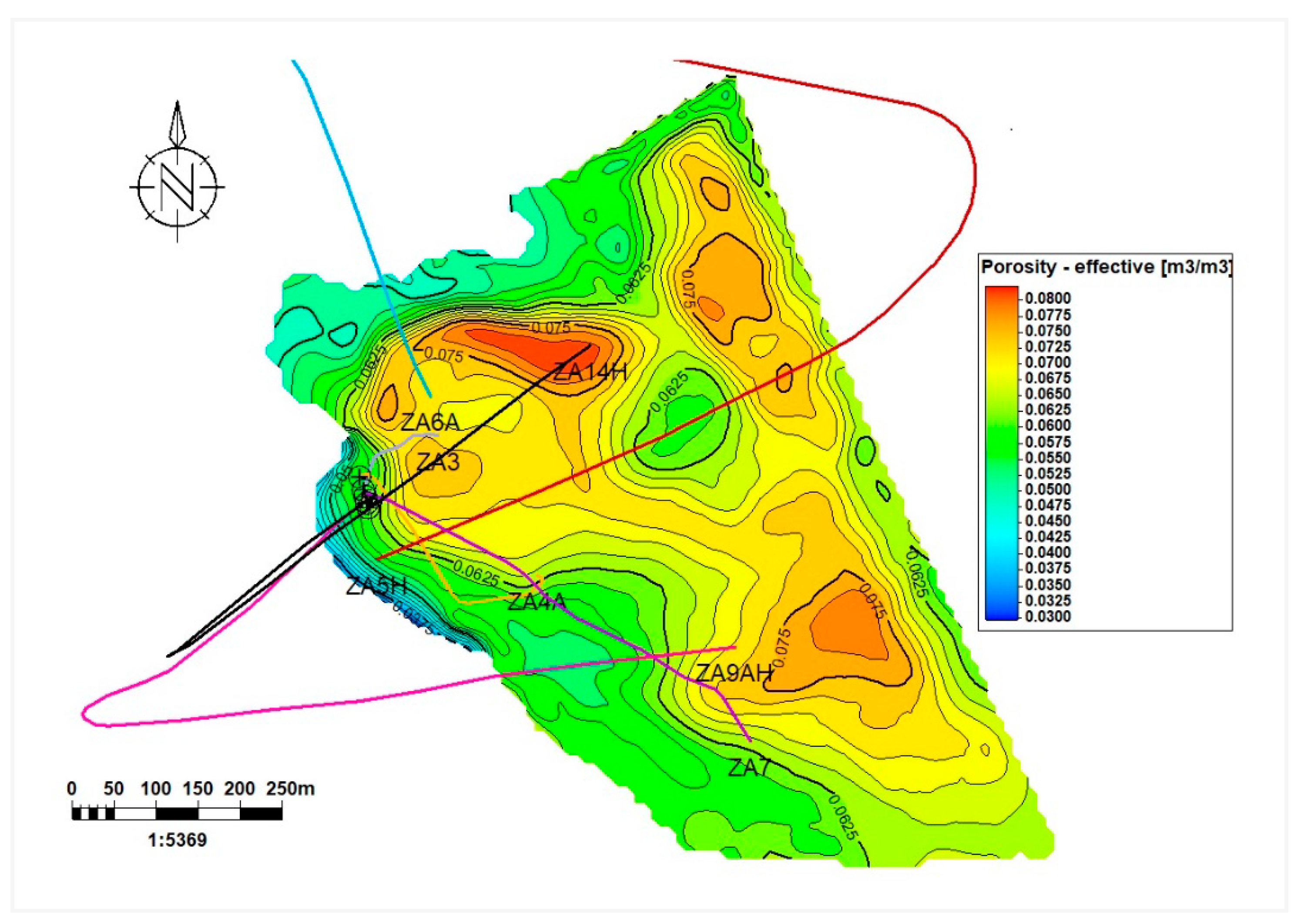
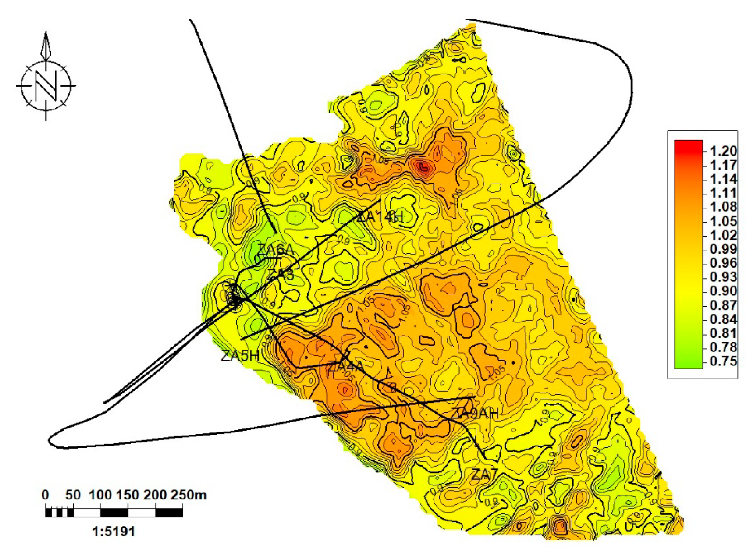
Several techniques were applied in a combination to distribute matrix porosity within the reservoir including density-neutron cross-plots and density, neutron and sonic logs, while the resulting porosity distribution was also corrected for the clay minerals presence.
Figure 5 illustrates porosity map resulting from geological model.
The initial water saturation was distributed using the resistivity of the formation water, effective porosity, cementing factor and Archies’s constant. Apart from the routine core analysis on small core plugs, a special core analysis (SCAL) was also carried out on the well-diameter core samples based on the core availability. The matrix permeability was distributed using the correlations with effective porosity and water saturation. Well test data and temperature logging were used to evaluate the temperature profile over depth. Finally, the Gaussian sequential simulation was employed to distribute the parameters described above within the reservoir volume.
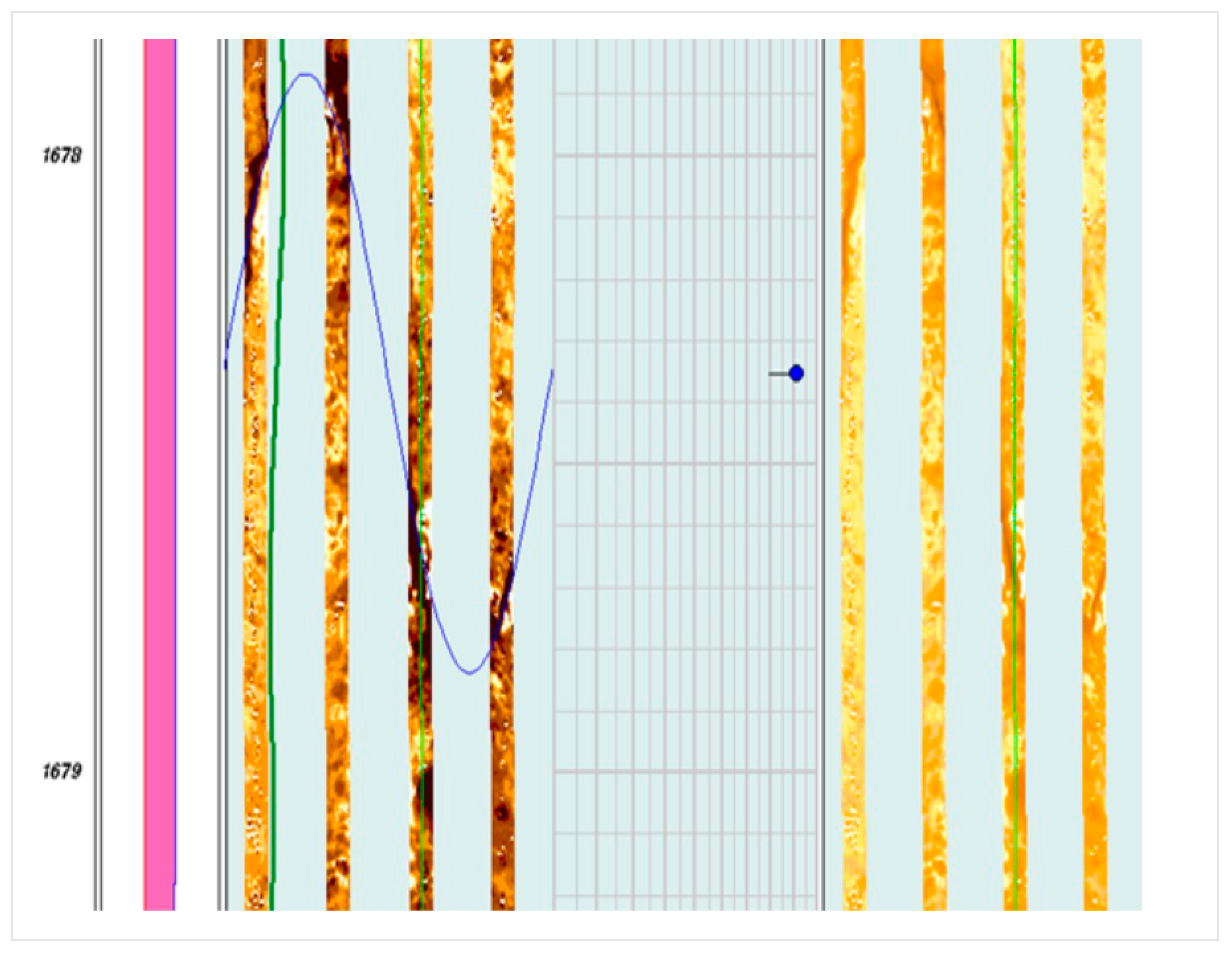
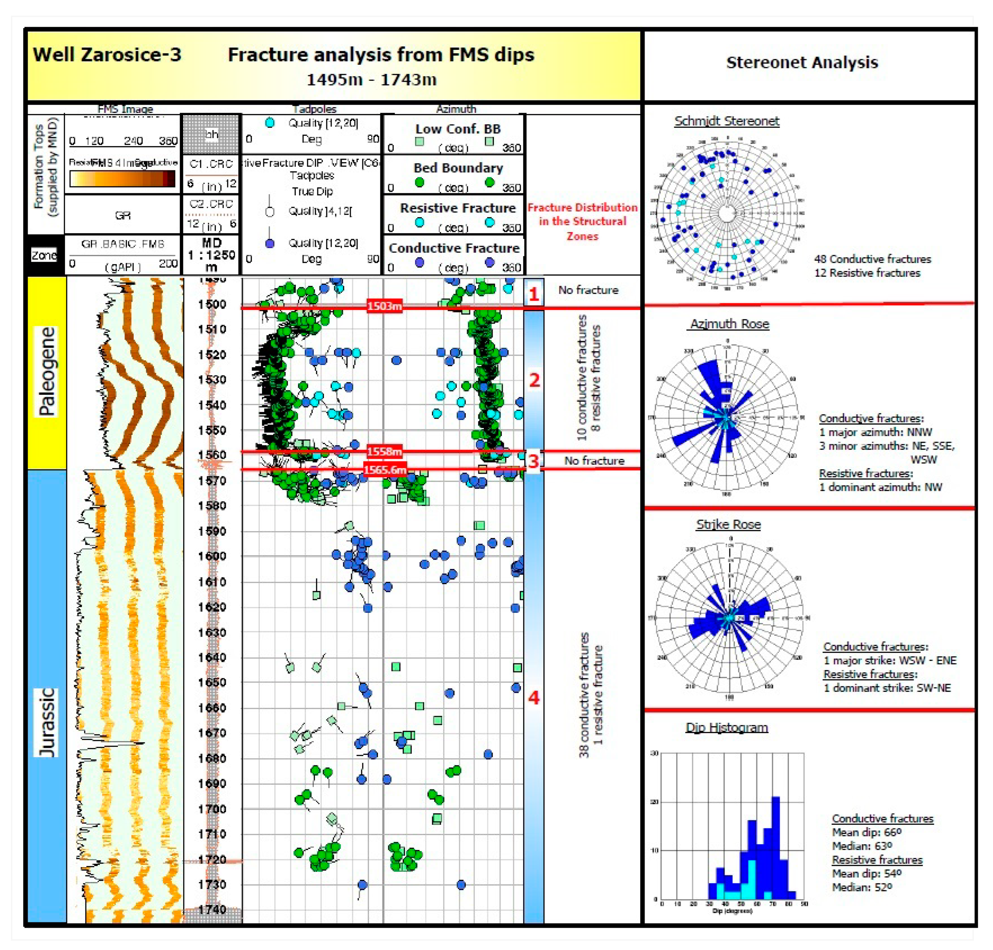
The reservoir in focus consists of naturally fractured carbonate rocks calling for special attention and specific methods for fracture assessment, characterization and modelling. The natural fracture networks were characterized using FMS logs obtained for seven wells penetrating the field. An example of the fracture analysis and characterization using the FMS data in ZA3 well is illustrated in
Figure 6 and
Figure 7. Unfortunately, these FMS data cannot be calibrated by core data since no oriented core samples are available.
The usual way for fracture modelling at the reservoir scale is to distribute the fracture properties obtained for particular wells in the whole reservoir volume using statistical characteristics of fracture sets. However, due to the large size of the geological model, this was not a viable option and a simpler process was used where densities of each fracture set (i.e., number of fractures per meter also termed as ‘intensities’) were distributed throughout the geological model using their statistical characteristics (mean orientation and dispersion). Map of the fracture intensity is displayed in
Figure 8. The resulting densities were then used to calibrate reservoir properties yielded from the well log analysis.
3.2. Dynamic Data Analysis
Based on the laboratory investigation of fluid properties the oil was identified as a medium heavy one with specific gravity of 910 kg/m3 and viscosity of 3.7 cP at the initial reservoir conditions. The gas is mainly methane (92%) with 4.8% other hydrocarbon gases and 3.2% nitrogen and CO2. The original static reservoir pressure was around hydrostatic pressure for the depths: 180 bars, and the reservoir temperature is 52°C.
The 20-year field production history is represented with different dynamic data sets including:
Pressure and rate measurements with different sampling rates (fragmentary for some wells).
Well tests carried for many wells, mainly in the beginning of production phase.
Periods of well monitoring with permanent downhole gauges installed (up to 2-year monitoring period per well).
These data were interpreted using a combination of Pressure Transient Analysis (PTA), including time-lapse PTA (Shchipanov, Berenblyum, & Kollbotn, 2014) and history matching with fit-for-purpose reservoir models using the Saphir software.
The objectives of this analysis were to:
estimate the reservoir flow capacity, defined by the permeability times the thickness (kh, respectively) and well performance, that include skin effects and effective well length for horizontal wells.
characterize the reservoir boundaries with mapping estimated reservoir properties (such as kh) to improve the reservoir description in the reservoir simulations.
evaluate the impact of fractures on flow capacity (like dual porosity and permeability effects) and fracture dynamics (like pressure-sensitivity of reservoir permeability).
design future well tests (to evaluate injection performance) and well monitoring plan with permanent gauges.
Many well tests including shut-ins at wellhead and downhole (using downhole shut-in tool) have been carried, mainly in the initial phase of production after drilling the wells. In addition, some production wells were monitored with permanent downhole gauges (PDG) resulting in long-term pressure measurements during multiple flowing and shut-in periods. These periods provided families of pressure transients which may be analysed separately or in a combination using time-lapse PTA methods (Shchipanov, Berenblyum, & Kollbotn, 2014).
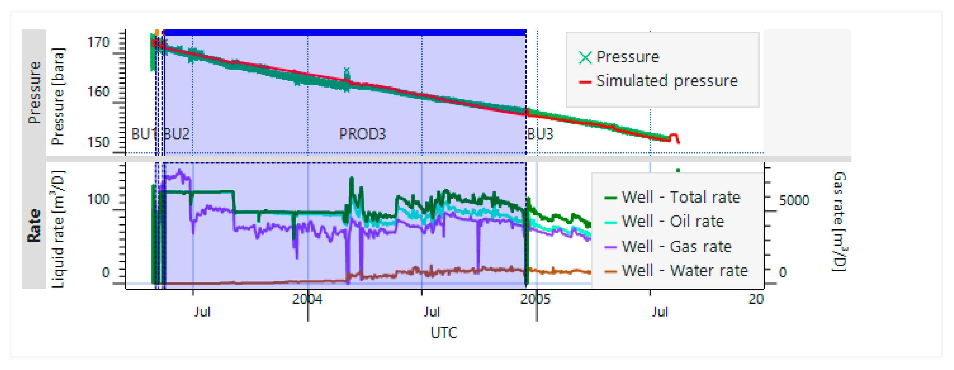
The most representative dataset is available for the horizontal production well ZA-5H drilled in the central part of the field (
Figure 9). This data were used in this paper to illustrate the time-lapse PTA application and its capabilities.
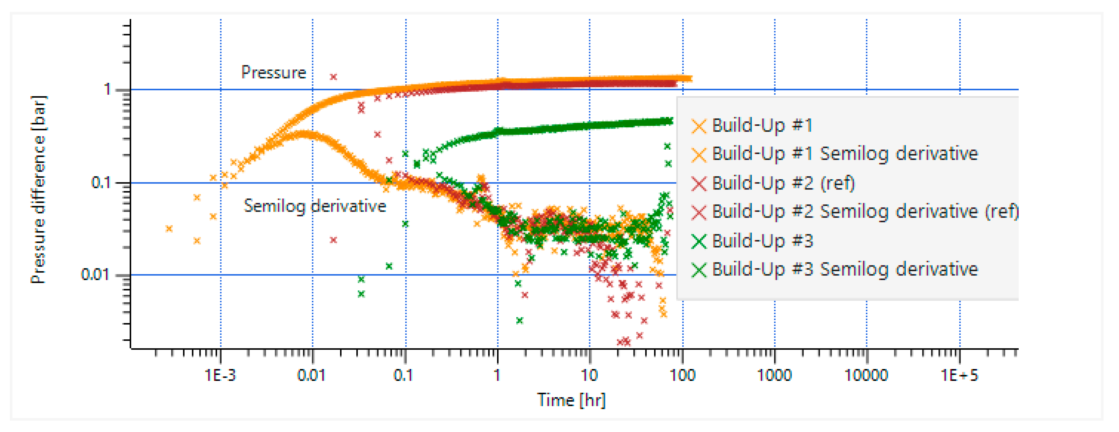
Figure 9 displays the PDG data at depth 2,484 m MD (at the bottom part of oil zone) for 2 years history since the beginning of well production, including a few flowing (production) and shut-in (pressure build-up) periods. During these two years, the well was producing above the bubble-point pressure with minor water-cut after half-year of pure oil production. Two shut-in periods with pressure build-up (BU1 and 2) and one following production (PROD3) period were analysed using the Saphir software to estimate well and reservoir parameters and reservoir boundaries.
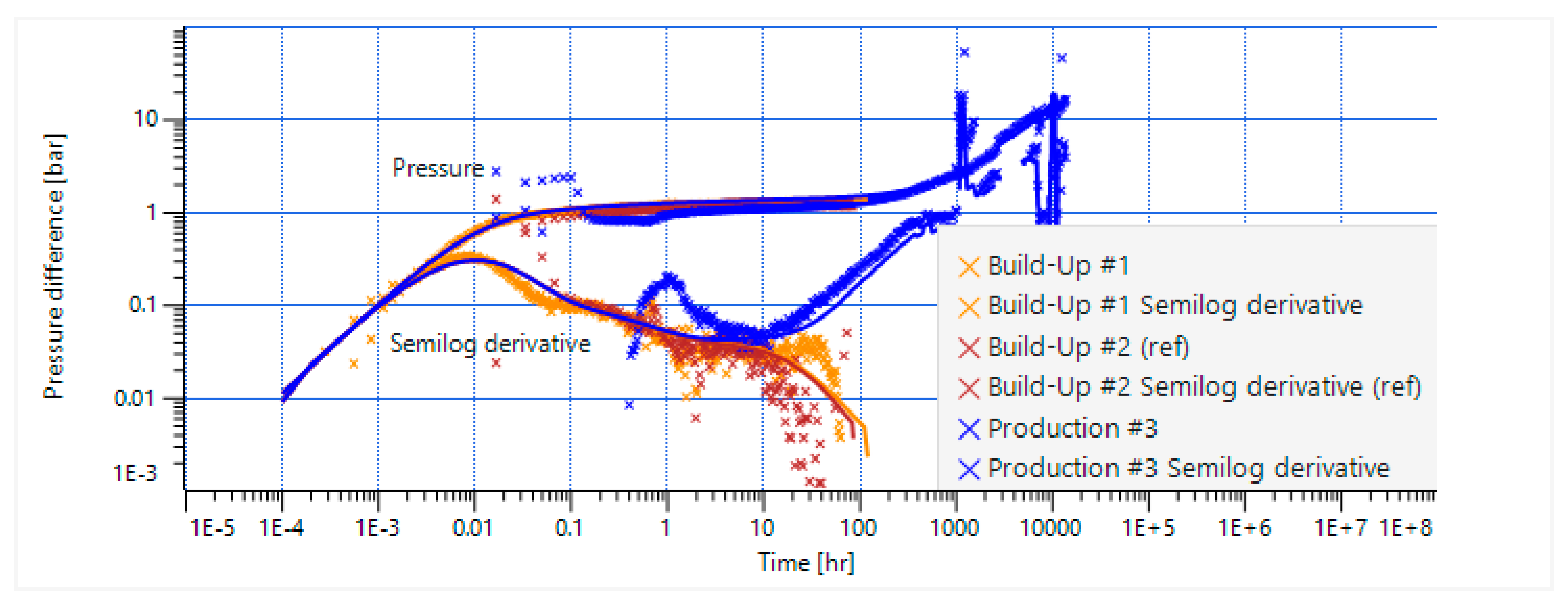
The production and build-up responses represented in log-log scale
Figure 10 clearly demonstrated a closed reservoir signature with no-flow boundaries. A fit-for-purpose analytical reservoir model was then used to estimate reservoir flow capacity,
, by using the stabilized pressure derivative level between 1 and 10 hr. This model reproduced the closed reservoir response recognized by an increasing derivative during production and decreasing derivative in the build-up periods at later times (i.e., after 10 hr).
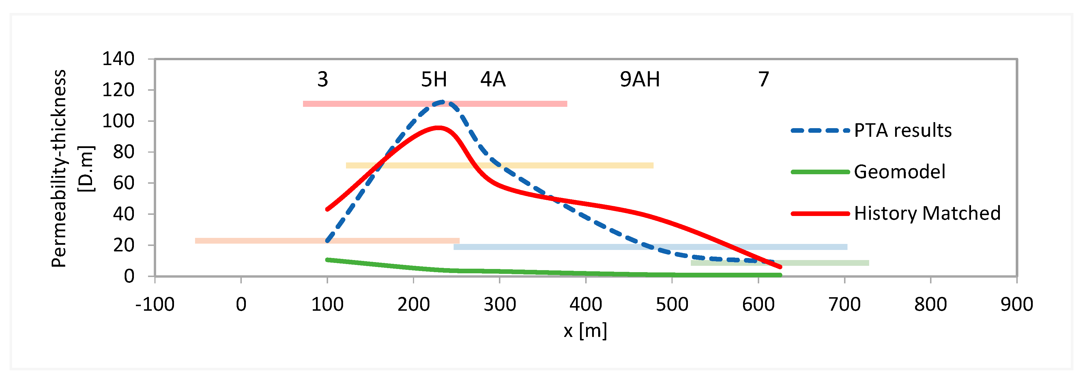
Similar PTA-interpretation was carried out for well test and pressure monitoring data for other wells (ZA-3, ZA-4A, ZA-9AH and ZA-7). Pressure build-ups were interpreted for most of the well datasets listed above, where single or repeated build-ups were available. The results of the reservoir characterization based on the dynamic data analysis may be illustrated with the reservoir flow capacity (
Figure 11) plotted versus a NW-SE cartesian axis crossing the wells ZA-3 and 4A (as shown in
Figure 4).
Among the objectives of dynamic data analysis, one was to evaluate how fractures impacted flow capacity including possible dual porosity and permeability effects, see (Bourdet, Ayoub, & Pirard, 1989), (Bourdet, 2002) . Moreover, understanding the dynamic fracture behaviour and pressure-sensitivity of overall reservoir permeability (Shchipanov A., Kollbotn, Surguchev, & Thomas, 2010) is key to develop a representative reservoir model that can also be employed for CO2 injection forecast.
The dual porosity and permeability effects are usually governed by the high porosity and permeability contrasts. While the matrix porosity may dominate over fracture volumes, the fracture permeability may dictate the overall flow capacity. This leads to fluid exchange between matrix and fractures, that is reflected in the specific ‘saddle-like’ signature in the pressure derivative (Bourdet, Ayoub, & Pirard, 1989), (Bourdet, 2002). The derivatives for the pressure responses analysed were quite noisy (
Figure 12), so identifying such ‘saddle-like’ signature confidently was difficult. Similar noise level is observed in most of the responses that have been analysed. However, some indication of the signature may be observed for the pressure build-up derivatives in
Figure 12 (in the period 1-3 hour) for the well in focus (ZA-5H). Meaningful interpretation with the dual porosity model was difficult in this case due to non-representative ratio of parameters to be applied to get derivative match. This signature may also indicate high-permeable (e.g. intensively fractured) area at some distance from the well. Similar indications of the signature were not found for other well responses analysed (keeping in mind the impact of the noise mentioned above), although further work in this direction may be useful for improving reservoir description.
A pressure-sensitivity of the overall reservoir permeability was observed for many fractured reservoirs, for example (Shchipanov A. , Kollbotn, Surguchev, & Thomas, 2010). The dynamic field data available were analysed to find indications of permeability variations caused by pressure changes. However, limited data have been available for such a study for this reservoir as tests of the same well were taken only in the beginning of the production for all wells, while permanent monitoring data covered relatively small pressure ranges. As an example, the three build-ups
Figure 12 may be compared in a time-lapse mode (Shchipanov, Berenblyum, & Kollbotn, 2014) to detect permeability changes, when characteristic shift (up and down) of pressure derivative may be observed. The comparison of build-ups 1 and 2 at reservoir pressure around 172 bar with build-up 3 at the pressure around 158 bar is complicated by high noise level (especially for BU3) making revealing permeability changes difficult. At the same time, the pressure range (158 to 172 bar) may be too small to govern significant permeability changes. As a result, it is difficult to judge about pressure sensitivity of the fractured reservoir taking data available and additional surveys (like well tests at different reservoir pressures) are needed to clarify this question. Step-rate test (Shchipanov, Kollbotn, & Prosvirnov, 2017) may be a good candidate to the additional survey, where well performance and permeability changes may be identified. The results of the geomechanical experiments described in the next section, which became available after this dynamic data analysis, argued that opening of the natural fractures may happen at pressures around 220 bar which is above the initial reservoir pressure (about 180 bar). This supports the observations made from the dynamic data analysis, although for quite narrow pressure range.
The following summarizes the dynamic data analysis:
Reservoir flow capacity (kh) and well performance (skin, eff. well length for horizontal wells) were estimated for five wells.
Reservoir characterization with kh mapping was carried out based on the results obtained for individual wells providing input for reservoir simulations.
Dual porosity, permeability and fracture dynamics (pressure-sensitivity) effects were not univocally observed from the interpretations of the field data available.
Additional well surveys, such as step-rate tests, may be designed using the fit-for-purpose reservoir models employed in PTA to evaluate injection performance.
3.3. Geomechanics
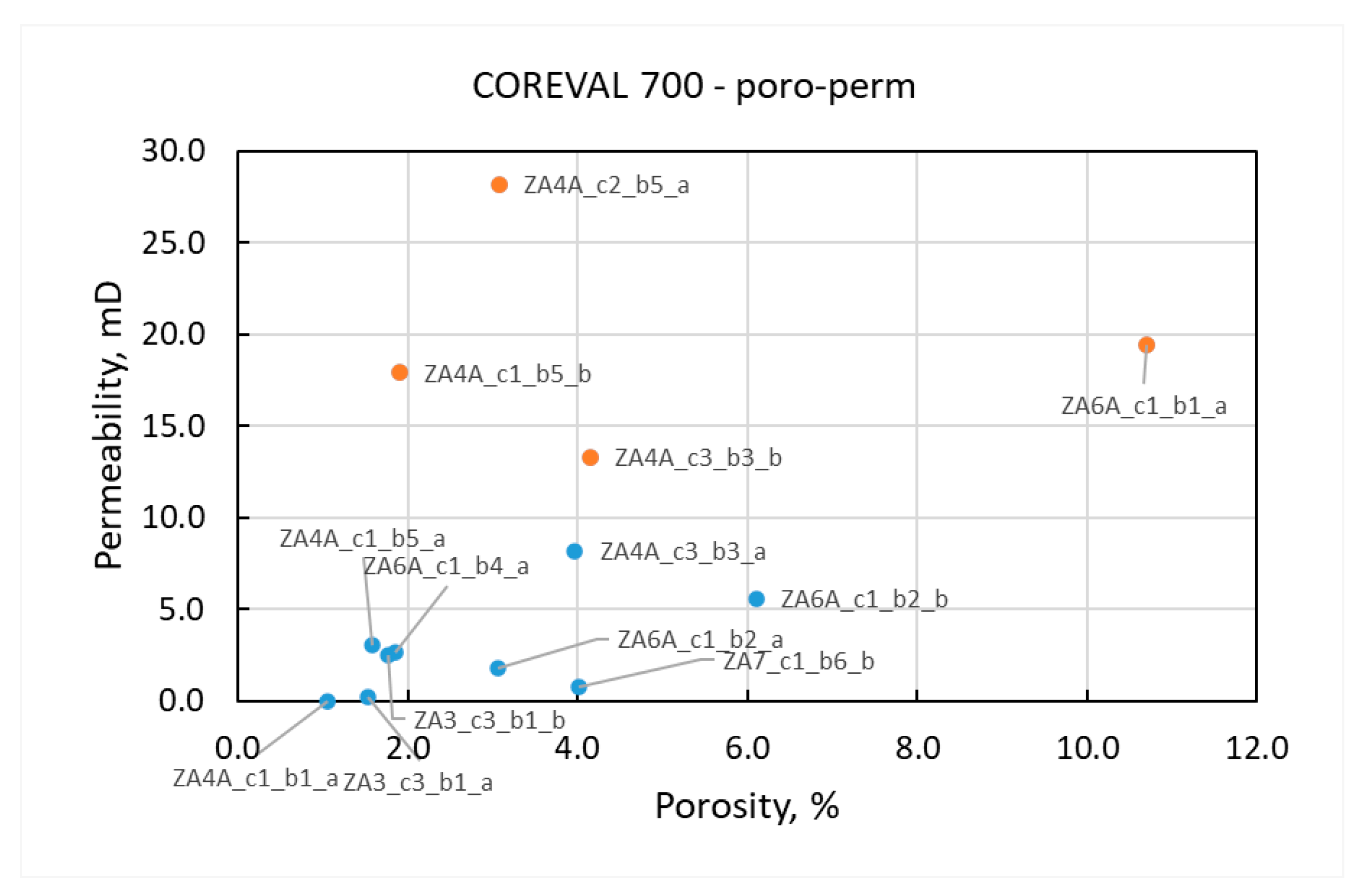
Geomechanical experiments on core samples from different parts of the reservoir complex were performed to determine elastic stiffness parameters, and plastic strengths in various stress geometries. Porosity and permeability estimated for different core samples are shown in
Figure 13 with description of the experiments in the
Appendix A.1 The whole database has been shared in (Nermoen, Porzer, Klempa, & Sancer, 2024), while the impact of cooling and re-pressurization on effective stress, when compared to the plastic strength, was used to constrain the safe operation envelope during CO
2 injection (Nermoen, Shchipanov, Porzer, & Sancer, 2024). Here, the envelope accounting for cooling and re-pressurization was assembled.
In this paper, data from the COREVAL 700-tool was used to determine how pore volume and permeability was affected by hydrostatic confining stress changes. This was done to estimate how porosity and permeability would change in respect to pore pressure by using the Biot effective stress concept. See
Appendix A.1 for a description.
Figure 13.
Porosity and permeability for the reservoir samples tested in the COREVAL 700 tool. Four high permeable samples are used to determine the transmissibility multiplier.
Figure 13.
Porosity and permeability for the reservoir samples tested in the COREVAL 700 tool. Four high permeable samples are used to determine the transmissibility multiplier.
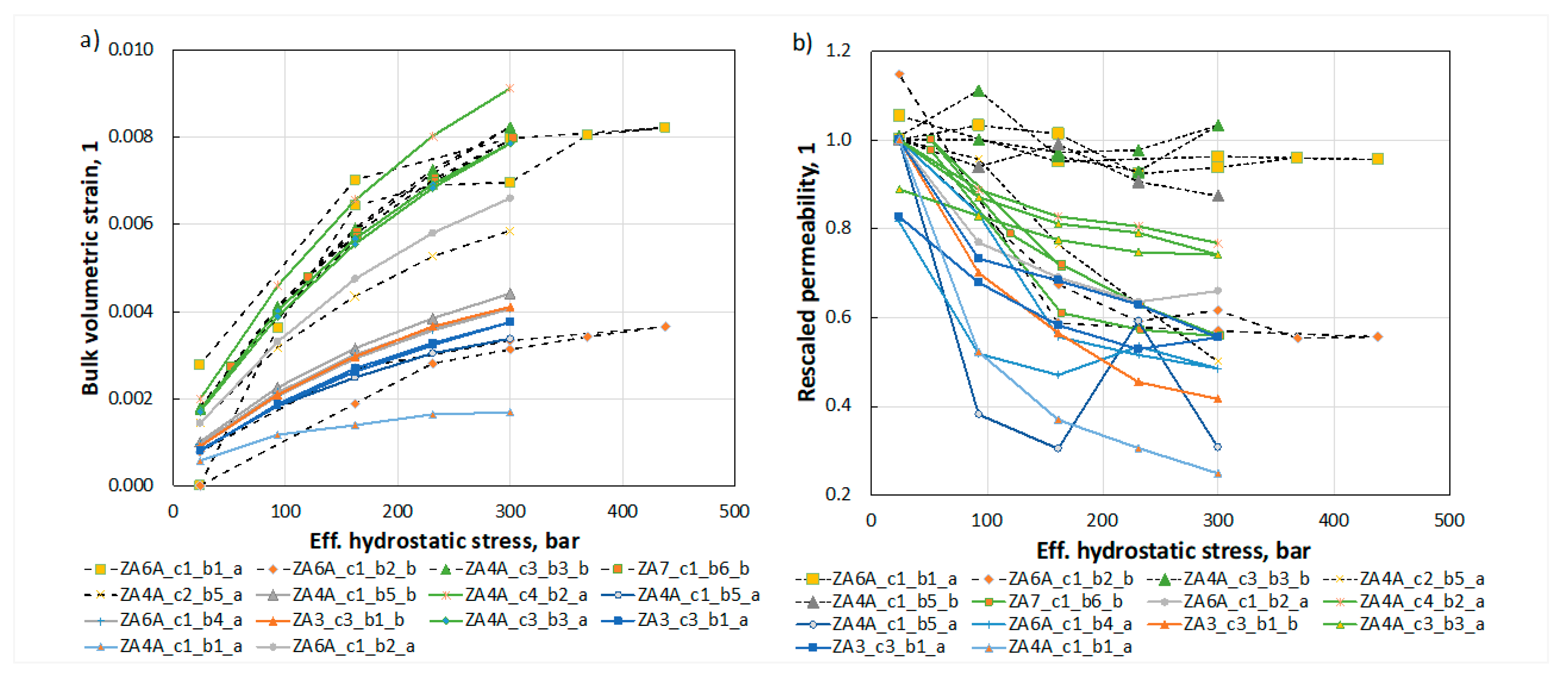
The results of all 14 reservoir samples are shown in
Figure 14a, for volumetric strain, and
Figure 14b, for rescaled permeability. A large variation between samples can be seen which is linked to the large geological variability in between samples as displayed in
Figure 13. With more than an order of magnitude differences in the permeability between the reservoir samples, the relation to confining stress becomes cleared when the permeability is rescaled by the permeability at the initial measurement of 21 bar (
Figure 14b). When calculating pore volume (porosity) and transmissibility (permeability) multipliers for the whole field (
Figure 15), only selected high porosity, high permeability samples with non-zero pore volume compressibility were used. These are marked with dashed lines in
Figure 14a and b.
The analysis is valid in the elastic domain, as the applicability of the effective stress relation is limited to reversible deformation. This data is integrated into the reservoir simulations to mimic how porosity and permeability change dynamically during the injection of CO2.
Figure 14.
Bulk volumetric strain (a) and (b) permeability rescaled by the measured value at 21 bars as function of Biot effective hydrostatic stress. For each curve, the well name, core and box number, porosity and permeability in unrested state is shown. Only reservoir samples displayed here.
Figure 14.
Bulk volumetric strain (a) and (b) permeability rescaled by the measured value at 21 bars as function of Biot effective hydrostatic stress. For each curve, the well name, core and box number, porosity and permeability in unrested state is shown. Only reservoir samples displayed here.
Because of the Biot effective stress principle, it is equivalent to vary pore pressure and the external confining stress in the elastic domain. Given the coordinate shift, as described in
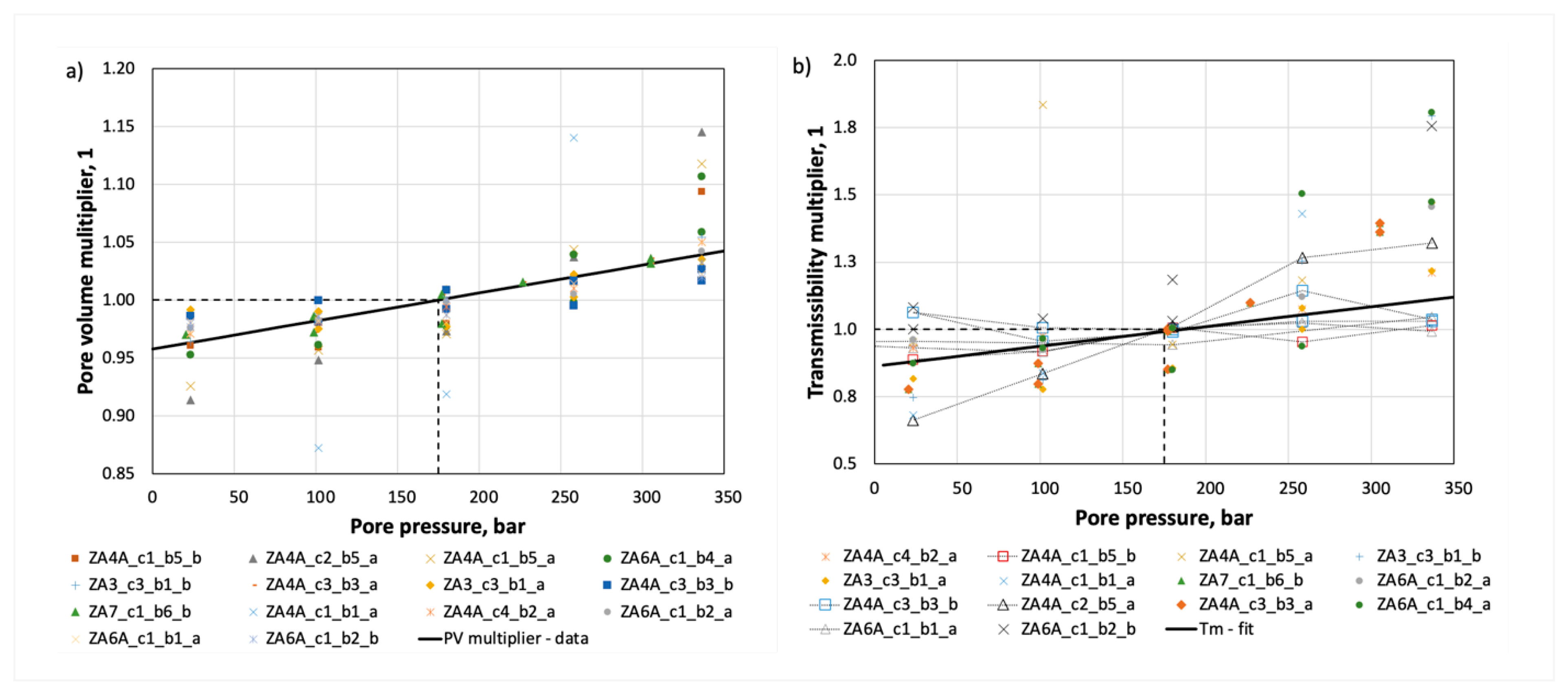
Appendix A.1, the estimated values were divided by the pore volume and permeability at 175 bar pressure so the pore volume and transmissibility multipliers were plotted (
Figure 15a and b, respectively). A large spread may be observed. The average response of the selected samples (dashed lines in
Figure 14a and b) is expressed as the solid black lines in
Figure 15a and b. It is assumed that these rock samples are more relevant to mimic the reservoir behaviour, dominated by fracture, not matrix, driven flow mechanics.
Figure 15.
Pore volume (porosity) (a) and transmissibility (permeability) (b) multipliers displaying the relation between pore volume, permeability and of pore pressure. The average relation from selected samples shown as solid line.
Figure 15.
Pore volume (porosity) (a) and transmissibility (permeability) (b) multipliers displaying the relation between pore volume, permeability and of pore pressure. The average relation from selected samples shown as solid line.
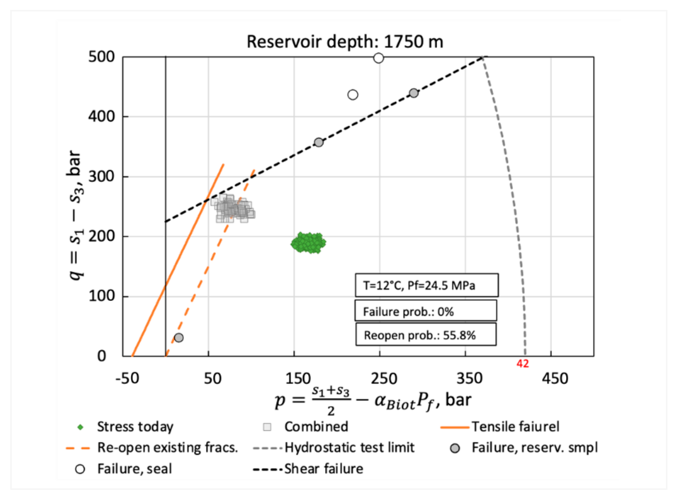
The geomechanical strength of reservoir samples were determined in the tensile regime by Brazilian tests, in the shear strength by Unconfined compressive strength and triaxial tests (Nermoen, Porzer, Klempa, & Sancer, 2024), and the stress-state at which pre-existing fractures occur is shown in
qp-space in
Figure 16. Given uncertainty in stress, Biot coefficient, thermal-elastic coupling coefficient and pore pressure, the initial stresses and the shifted stress-configuration are displayed as green and grey areas in
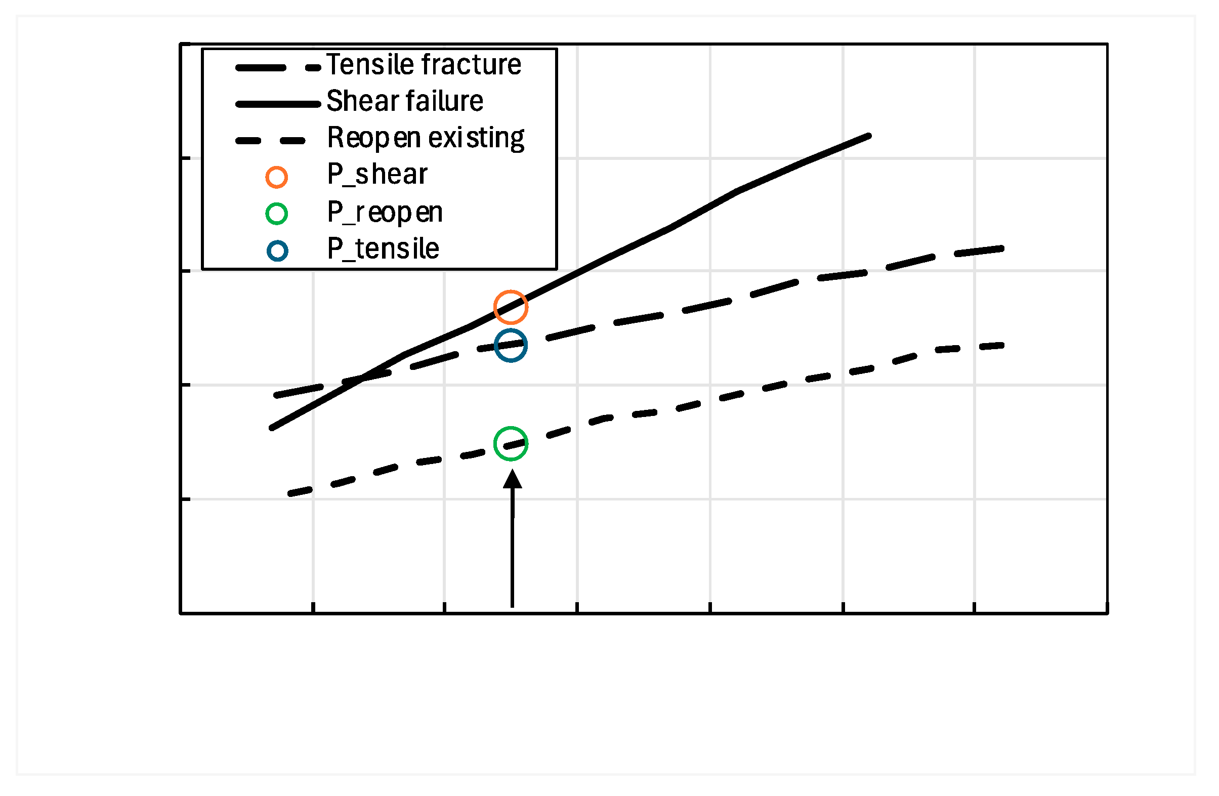
Figure 16 using Monte Carlo techniques (Nermoen, Shchipanov, Porzer, & Sancer, 2024). This enables the calculation of the pore pressure and reservoir temperature at which 1% of the simulated cases were geomechanically unstable (
Figure 17). Here, the pressure at which re-opening of pre-existing fractures, generating new tensile fractures and shear failure can be determined for each temperature.
As the COREVAL 700 tool enables a physical relation between pore pressure, pore volume and permeability, this is only valid in the elastic regime for intact rocks. When the pore pressure exceeds the least tectonic stress (224 bars), however, fractures will re-open. This will lead to a significantly increase the permeability as displayed in
Figure 18, where the estimated permeability and porosity multiplier is plotted, while calculated permeability multiplier is calculated as an exponential function of pressure. If pore pressure further exceeds the least tectonic stress plus the tensile strength (267 bars) new fractures will develop. This was however not accounted for in the multipliers in
Figure 18, since maximum injection pressure in the pilot injection scenarios is limited by the induced fracturing pressure (267 bars).
The critical pressures above rely on certainty of the input geomechanical data (i.e. the actual value and likely range), the risk appetite of the operator reflected in the probability of failure (here 1%), and temperature.
3.4. Compositional Effects
A new compositional model was created for the history matching and prediction period. The PVT data available provides a standard set of PVT experiments for the oil reservoir conducted at reservoir (52 0C) and close to standard (19 0C) conditions, however, does not address potential CO2 interaction with reservoir fluids, as it was not relevant at a time of study. An SRK equation of state was tuned to available data and both black-oil and 8-component compositional models were created. The models showed good match for relative volumes, densities and viscosities with deviation within several percent.
Different correlations were used at reservoir temperature including uncertainty to reservoir fluid parameters to estimate compositional interaction between CO
2 and reservoir fluids (
Table 1).
Judging by the correlation results, the minimum miscibility pressure is in the range of 153-182 bar, which is within the reservoir pressure range. A detailed CO2 PVT study will be needed if this reservoir will be considered for CO2-EOR, which can become an efficient oil recovery technique. For the current study, where the model is used for evaluating the pilot injection into the aquifer zone, the MMP between the CO2 and reservoir oil was set at 165 bars at 52 0C.
For the sake of reducing the simulation time in the current study, as, again, only the pilot CCS scenarios are to be simulated, the black-oil model representing CO2 through the solvent option is used.
3.5. Geochemistry Effects
As CO2 is injected into reservoirs, the near well region is exposed to proportionally huge volumes of CO2. It is then important to evaluate that the risks of formation damages are low, e. g. by salt precipitation, hydrate formation, fines migration, bacteria activity, temperature and pressure cycling (Hansen, et al., 2013) (Sminchak, Zeller, & Bhattacharya, 2014) (Zettlitzer, Moeller, Morozova, & Lokay, 2010).
Among geochemical effects two may have strong impact on pilot CO2 injection:
Hydrate formation is a function of temperature, pressure, and salinity. The hydrates form in higher pressure, lower temperature, and lower salinity environment. For the 180-200 bar system (high pressure in the vicinity of the injection well) of relatively low salinity a CO2 bottom hole temperature of around 15 degrees should prevent hydrate formation. With the expected low-rate injection in the pilot phase and geothermal heating as it travels down the well seem to provide a safe operational regime. Hydrate precipitation is therefore considered as a very low, easy to mitigate risk and will not be a part of reservoir simulation study.
Potential salt precipitation seems to be the major risk factor for well infectivity during pilot CO2 injection. Injection of dry CO2 phase will evaporate water in water-bearing formations (Miri & Hellevang, 2016). The concentration of ions in the water phase may then gradually increase until maximum solubility is reached, and salt precipitation may then occur. The potential of salt precipitation depends on several parameters, e. g. water-phase composition, residual water saturation, flow rate, pressure and temperature. The risk for permeability reduction by salt precipitation depends on the location of the precipitate in the pore-space and thereby on rock properties, fluid compositions and local flow regimes.
Formation damage by salt precipitation includes three main mechanisms: salt precipitation, migration of salt crystals and accumulation of crystals at pore throats (Ott, Snippe, & de Kloe, 2021). All these mechanisms should be included in modelling/simulations of the process. It has been reported that modelling of vaporization by equilibrium cannot describe core flooding experiments in a good way (Ott, De Kloe, Marcelis, & Makurat, 2011).
Salt precipitation has been reported to cause pressure build-up and loss of injectivity in CO2-projects. Studies related to the Ketzin project have reported dry-out radii in the range 3.8 – 13m, and maximum halite saturations in the range of 3%-80% (Baumann, Henninges, & Lucia, 2014). For the Snøhvit project, a dry-out radii of 0.7m was estimated for one reservoir zone (Grude, Landrø, & Dvorkin, 2014). The salt precipitation was reported to be removed by injection of monoethylene glycol. In some other CO2-projects, salt precipitation has been found to give complete blockage of perforations and near well region, e.g. Aquistore project (Talman, Shokri, Chalaturnyk, & Nickel, 2020). In the literature mainly experiments with permeability reduction has been reported (up to 83%), but also some experiments with increase in permeability (Miri & Hellevang, 2016).
Injection of CO2 into aquifers of high porosity and permeability rock will give longer migration due to the injection pressure (Cui, Hu, Ning, Jiang, & Wang, 2023). A large dry-out zone can be formed in the near well regions of these reservoirs. The CO2-water capillary pressure in these zones is low, and the effect of capillary pressure on salt is therefore low. Salt precipitation is often not causing much formation damage in these reservoirs. For rocks with low porosity and permeability, the CO2-water capillary pressure is high and salt precipitation becomes more important. The irreducible water saturation is much higher and the smaller pore throats is easier to block by salt precipitation. The low porosity and permeability give more back flow of brine to the well-bore due to the high CO2-water capillary pressure. This causes more salt precipitation to occur in the near-well region. Blockage of pore throats and low CO2 injectivity can occur even though the salinity is not very high.
The extension of the dry-out / salt precipitation zone depends on parameters as brine compositions, rock properties, flow regimes and time (Miri & Hellevang, 2016), (Afanasyev & Grekho, 2023). (Cui, Hu, Ning, Jiang, & Wang, 2023) found the extension of the dry-out zone to be large in high porosity and permeability formations with not much formation damage, but less extension in low porosity and permeability formations with larger formation damage. The dry-out zone can be tens of meters as reported for CO2-projects (Baumann, Henninges, & Lucia, 2014), (Grude, Landrø, & Dvorkin, 2014). (Hurter, Labregere, & Berge, 2007) reported for a rock of 200 mD a zone of 10 m in 2 years, and (Pruess, 2009) found the zone to be a few meters for a rock of 33 mD.
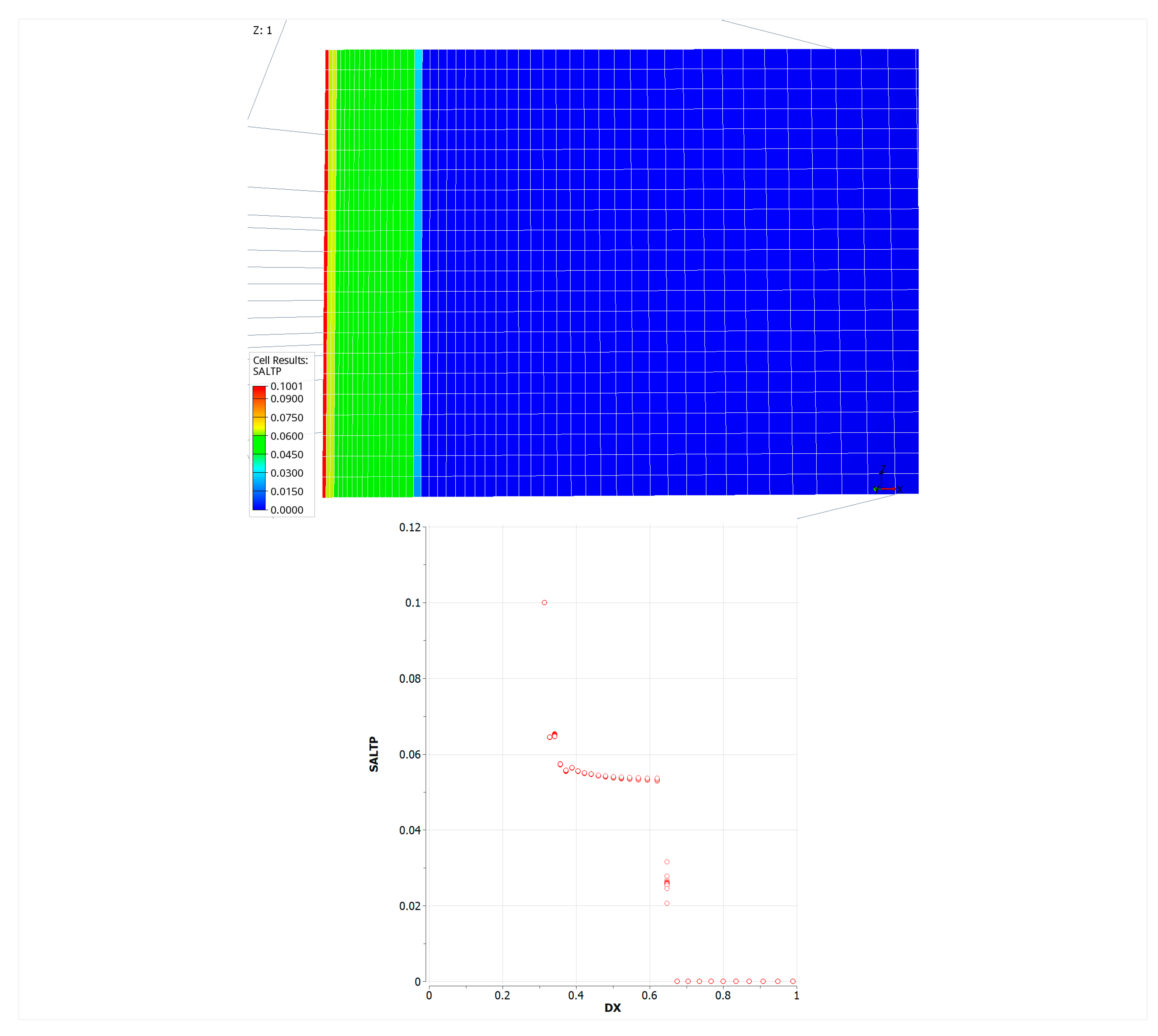
A mechanistic simulation was carried out to study salt precipitation near the wellbore. The reservoir salinity is 12 200 mg/l with chloride and around 26 000 mg/l if all ions are taken together. The near wellbore reservoir simulation was used to estimate the scale of salt precipitation in this case (assuming 25% residual water saturation, 60 m pay depth and 30 mD permeability). Maximum salt precipitation reached 10% in the cell containing the well itself. After approximately half a year of injection the salt precipitation zone stabilized, affecting in total only around 0.6 m around the wellbore. This study in combination with the literature referenced above were used as a reference for suggesting salt precipitation potential for the field in focus. The ranges for potential permeability reduction and the size of the near wellbore area affected by the salt precipitation were then assessed as: 10 - 80% and 0.5 - 5 m correspondingly. These range were further converted into well skin factor (flowing
Appendix A.2) and applied in the sensitivity studies of the CO
2 injection scenarios.
Figure 19.
Salt precipitation in the near wellbore area (full cross-section on the left) and concentration of precipitation salt vs distance first meter from the well on the right.
Figure 19.
Salt precipitation in the near wellbore area (full cross-section on the left) and concentration of precipitation salt vs distance first meter from the well on the right.
3.6. History Matching of the Reservoir Model
The geological model shortly described in the section 3.1 was used as the basis for reservoir simulations. The model included the following reservoir properties: matrix porosity and permeability as well as fracture intensity distributed at the fine geological grid with grid-blocks of 10 x 10 x 1 m. These properties were redistributed on upscaled grid (10 x 10 x 5 m) suitable for reservoir simulations in the Eclipse software using the black-oil fluid flow model. Aiming at further reduction unneeded grid blocks laying in aquifer, out of the hydrocarbon bearing area, a large part of the resulted aquifer grid-blocks were made inactive and replaced with the Fetkovich analytical aquifer model.
Based on the interpretation of the well, field and experimental data available, the single porosity and permeability approach for reservoir flow simulations has been chosen. The choice was driven by the following arguments (following the studies summarized in the previous sections):
It’s assumed that the pore volume is mainly constituted by pores and fracture-associated vugs.
Dual porosity effects were not interpreted from analysis of the pressure transient data available (dual porosity signature in the pressure derivative) and production history (e.g. fast horizontal water breakthrough in the horizontal direction between the injection and production wells).
Effective permeability of the fractured reservoir was estimated from analysis of the dynamic data available for many wells and distributed throughout the reservoir. The effective permeability estimated is much higher (50 - 1000 mD, resulted in flow capacity in
Figure 11) than the values obtained from the core measurements: 0.01 - 30 mD (
Figure 13), which represent mainly the matrix permeability and, in comparison to the core measurements, the dynamic data analysis represents reservoir-scale estimations (no need for upscaling from lab-to-field level).
The fracture porosity estimation looks unattainable task, since the fracture description is limited by fracture density without possibility to estimate fracture apertures and length.
Based on the arguments above, the series of fit-for-purpose reservoir simulations were carried out within the single medium concept in dynamic data analysis and evaluation of salt precipitation effects described above. These simulations contributed to the full-field reservoir model update.
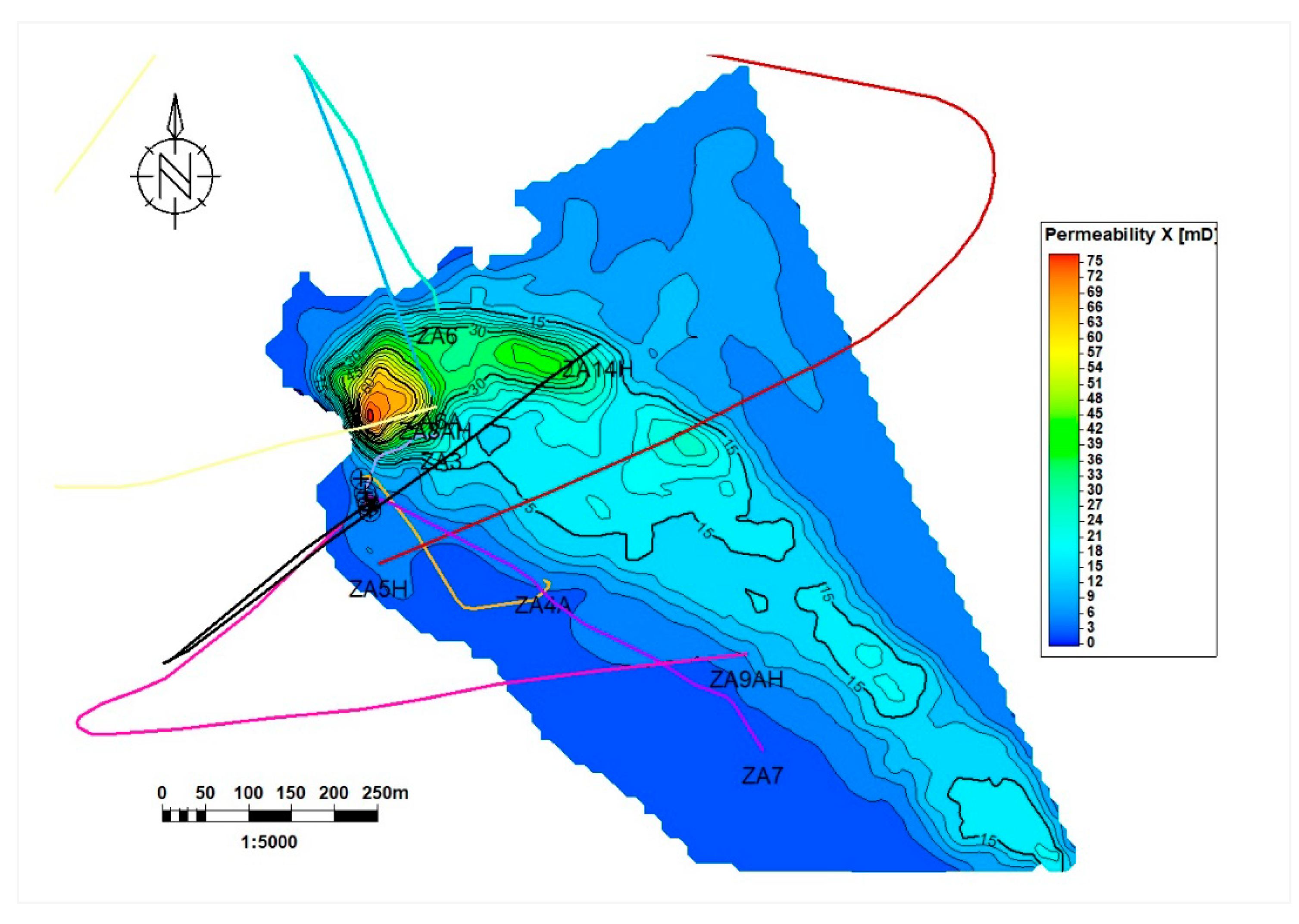
As the next step, pore volume and transmissibility multipliers obtained from the geomechanical study described in the section 3.3 were specified. The resulted first version of the full-field model was then used to condition the matrix permeability distribution to the results of the dynamic data analysis summarized in the section 3.2. The matrix permeability resulted from the geological modelling (
Figure 20) was first conditioned to the fracture density distribution (
Figure 8) and then to the permeability-thickness product obtained for different wells from the dynamic data analysis (
Figure 11). The well-based multipliers were then inter- and extrapolated to the inter-well reservoir volumes using the moving average method available in Petrel.
The resulted permeability distribution was then tested in reproducing the field production history. It should be mentioned that implementing and distributing of the well-based permeability multipliers obtained from the dynamic data analysis is a task complicated by understanding which areas these values should be assigned to and how to inter- and extrapolate these multipliers in the inter-well area of the reservoir. Thus, radius of investigation from Pressure Transient Analysis (PTA) was assigned to the multipliers obtained for the wells in the dynamic data analysis. Additional spatial control of the multiplier distribution was applied to control the distribution in the inter-well area.
The updated permeability distribution obtained via the conditioning of the fracture-density initially conditioned permeability to the well-based multipliers was tested in history matching exercises. Here, matching the well pressure history and well pressure drops were paid the main attention. Further fine tuning of the multipliers for some wells was carried out to match the well measurements. As an example, the pressure history match for the well ZA3 is shown in
Figure 21. This fine tuning has provided some deviations of the resulted permeability-thickness product, if compared to the dynamic data analysis in
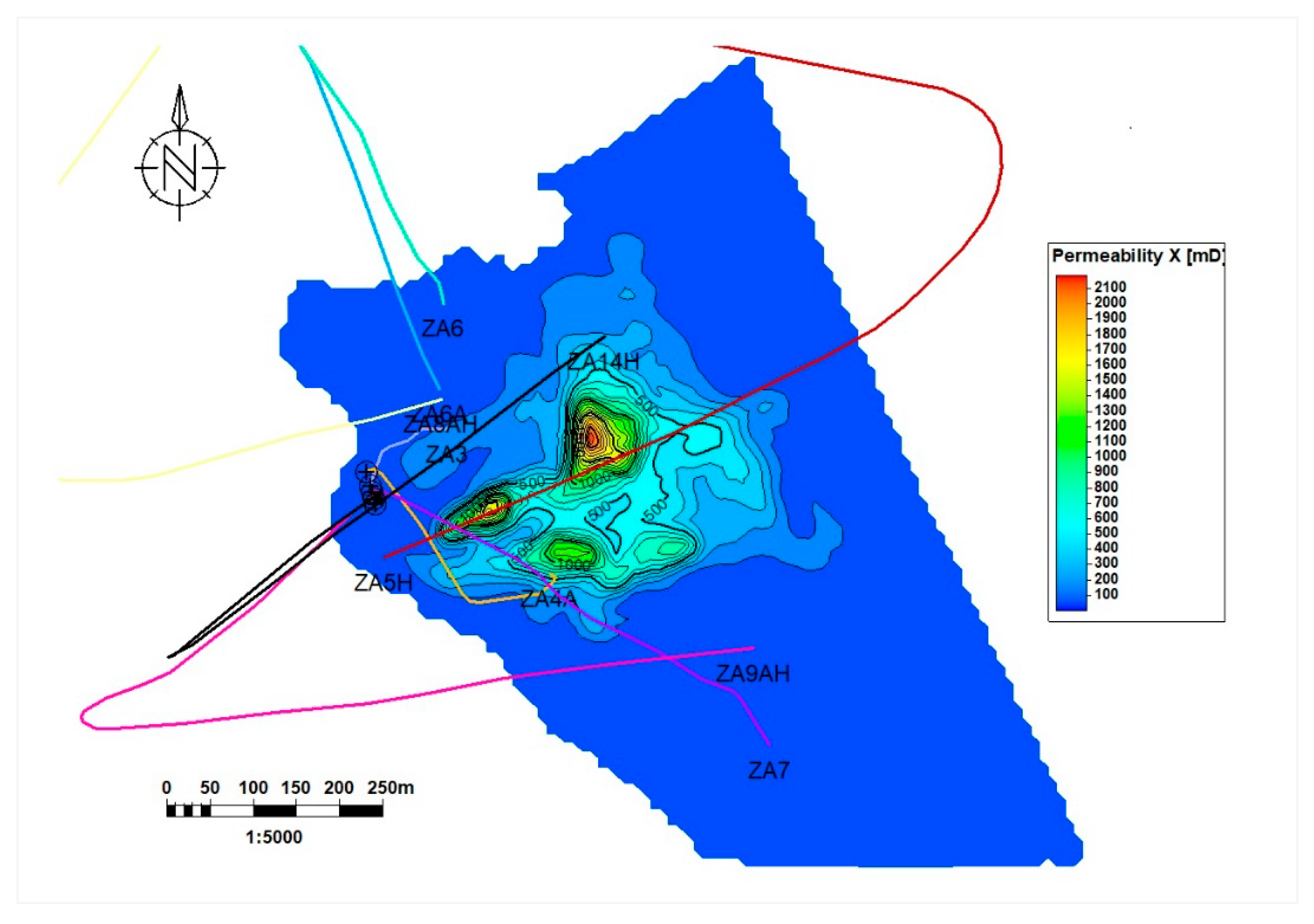
Figure 11. At the same time, reasonable match of pressure history for all the wells has been achieved. For some wells, additional minor permeability adjustments were carried out to match observed gas-oil ratios and water-cuts in individual producers. As a result of the conditioning of the permeability distribution to the dynamic data analysis results as well as matching to the production history, the final permeability map was obtained as shown in
Figure 22.
The results of the history matching of the full-field reservoir model may be illustrated with the history of the ZA3 well (the discovery and the first production well in the field). Having long open-hole interval in the oil zone, the gas from the gas cap reached top part of the open hole increasing gas-oil ratio (GOR) to the level that the production from the well was terminated. Since 2006, the producer was used as an observation well allowing occasional (with retrievable gauges) measurements of static bottom hole pressure (BHP). The pressure measurements were useful in the history matching process allowing to adjust initial hydrocarbons’ volumes and aquifer size and may also be used to evaluate the history matching results. The comparison of the pressure measurements (circles) and the BHP simulation results (line) displayed in
Figure 21 indicate reasonable matching of the measurements by the simulation results. Achieving these history matching results, the reservoir model was further used for simulation of the pilot CO
2 injection scenarios.
3.7. Simulation of Pilot CO2 Injection
The pilot CO
2 injection scenarios were set up taking into account the safe operating envelope resulted from the geomechanical evaluations described in the section 3.4. The highest risk scenario of cold CO
2 injection at 15°C was assumed resulting in the natural fracture opening at 224 bar and induced fracturing pressure at 267 bar (
Figure 17), which was considered as the maximum injection BHP in the simulations. The impact of geochemical effects related to potential salt precipitation in the near wellbore area was evaluated via sensitivity runs for the well skin factor following
Table A1.
The solvent model, which is a four-component extension of the Eclipse black-oil model, was used allowing introducing CO2 properties as the fourth reservoir fluid in addition to gas, oil and water. The main scenario of pilot CO2 injection was considered with injection into ZA7 well penetrating water zone. The pilot injection scenarios assumed commencing CO2 injection without preceding gas cap depletion, where injection starts at the current reservoir conditions. An alternative scenario of gas cap depletion with following CO2 injection may also be considered, but it is outside of the scope of this study.
The legislation of the Czech Republic allows for cumulative injected volume at maximum 100 thousand tons of CO2 for a pilot injection. Following this restriction, the pilot injection volumes were chosen as the mass injection rate of 44 thousand ton per year during nineteen months with 70 thousand tons injected in total.
One of the main advantages of the commencing the CO2 injection at the current reservoir conditions (before the gas cap depletion) is that the reservoir pressure remains sufficiently high avoiding the Joule–Thomson cooling effect observed at injection at low reservoir pressure. Another benefit here is CO2 injected and flowing inside the reservoir in the supercritical phase.
The ZA7 well was chosen as the CO2 injector profiting from the fact that the well is currently being used for produced water injection. The well was recently re-completed with fiberglass tubing, which makes it perfect candidate for the CO2 injection, without significant additional costs for converting it into CO2 injector. The nearby ZA3 well is currently used as an observation well and therefore may be further used for reservoir monitoring during the pilot CO2 injection. The well ZA7 penetrates aquifer part of the field and CO2 is therefore injected into the water zone.
Following the main CO
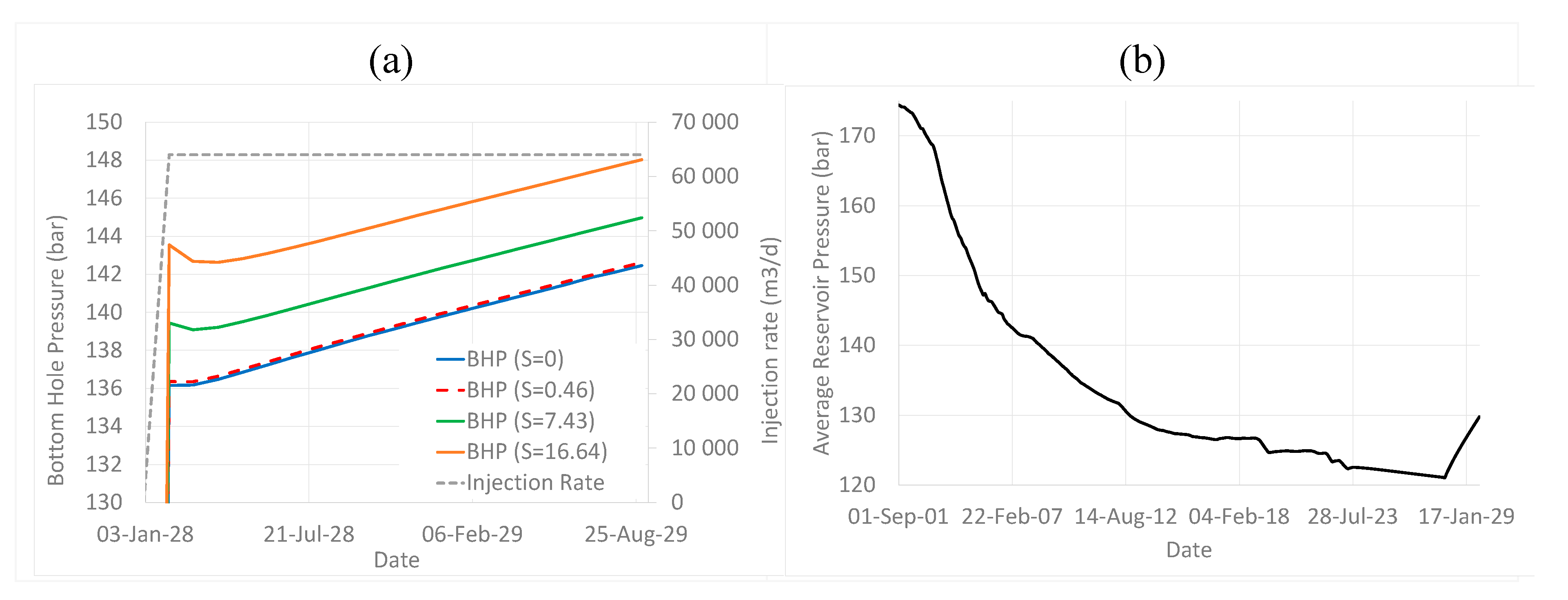
2 pilot injection design described above, the injection with the mass rate of 120 tons per day during the pilot injection period within 583 days (with 70 thousand tons cumulatively injected) was simulated. As the injection rate is relatively low, calculated BHP in the injector increased during the pilot period only by 6 bars (from 137 to 143 bar), as it can be observed from
Figure 23a.
Corresponding increase in the average reservoir pressure is shown in
Figure 23b in comparison to the pressure depletion from 174 to 121 bar during the production history. Simulation results predict minor reservoir pressure increase by 9 bar (from 121 to 130 bar) during the pilot injection.
The injected CO
2 has lower density than formation water and oil, but higher than gas in the gas cap at the current reservoir pressure and temperature. Consequently, the injected CO
2 is first accumulated around the ZA7 injection well forming a small CO
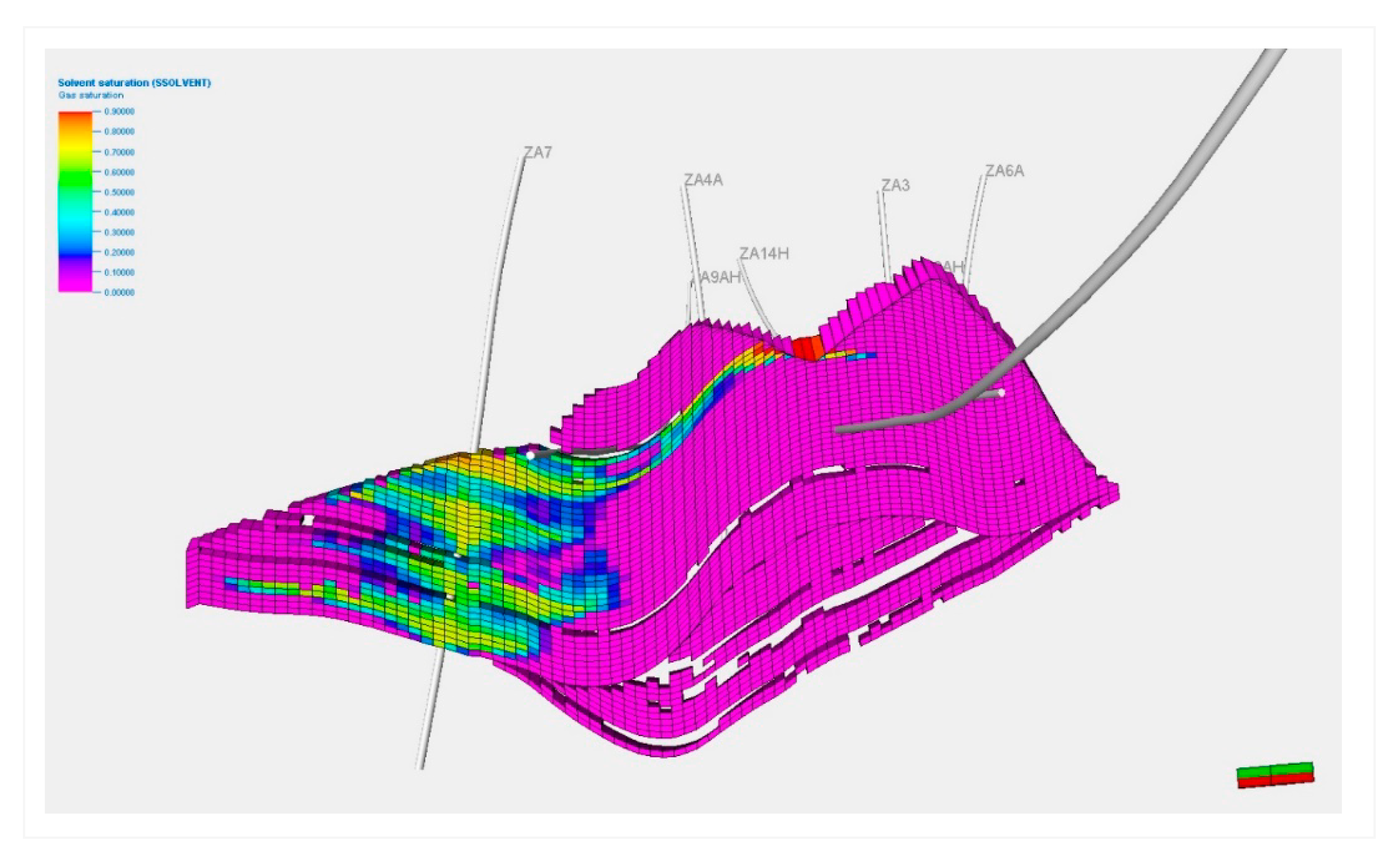
2 plume, starting to migrate throughout the formation structure (oil zone) and segregate by gravity at the top of the oil zone and bottom of the gas cap as illustrated in
Figure 24.
Additional simulations were carried out to quantify uncertainty associated with possible salt precipitation in the main pilot injection scenario. As discussed in the section 3.5, salt precipitation may cause permeability reduction in the near wellbore area of a certain radius, which can be modelled by increasing skin value in injection well following
Appendix A.2. The sensitivity was run for the permeability reduced by 10 and 80% and the radius of the near wellbore area with the reduced permeability varying from 0.5 to 5 m. These ranges resulted in the skin values of 0.21 (10%, 0.5 meters, ignored further since is very close to zero), 0.46 (10%, 5 meters), 7.43 (80%, 0.5 meters), and 16.64 (80%, 5 meters), see the
Appendix A.2. The pilot simulation described above assumed zero skin and was used as the reference case for the skin sensitivity. The skin sensitivity of the pilot injection scenario is shown in
Figure 23a and demonstrates about 6 bar of additional pressure drop due to skin in the most risky scenario with skin of 16.64. So, presence of skin may double the BHP build-up during the pilot injection (achieving 148 bar), although the BHP remains far from the natural fracture opening pressure (224 bar).
Figure 24.
CO2 saturation at the end of the pilot injection.
Figure 24.
CO2 saturation at the end of the pilot injection.
As a final step, potential CO
2 injection capacity of the reservoir assuming injection at the maximum pressure of 267 bar corresponding to the induced fracturing pressure following the geomechanical evaluations for the temperature of 15 °C (
Figure 17) was estimated. Here, since the well BHP may overcome the fracture opening pressure of 224 bar, effect of fracture opening was also studied applying two permeability multipliers: accounting and not accounting for the fracture opening (
Figure 18). In addition, the well skin sensitivity (due to the salt precipitation) was studied similarly to the simulations of the pilot injection above.
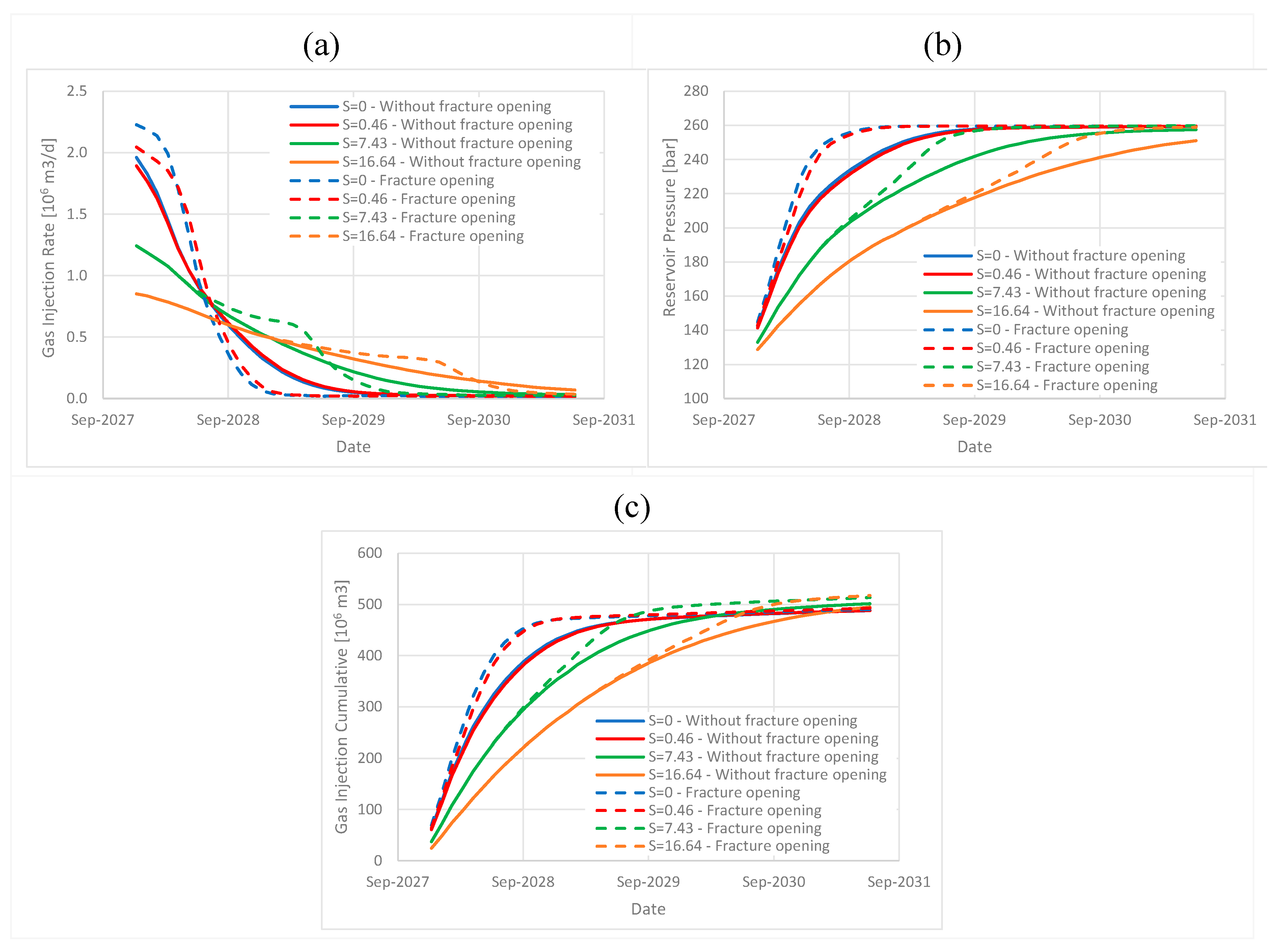
The simulation results in
Figure 25a showed that CO
2 injection rate is significantly higher for the cases of low or no skin (0 and 0.46), since reservoir pressure in the near wellbore area is close to BHP (267 bar), which is much higher than the fracture opening pressure. This causes high pressure in the near wellbore area and opening the natural fractures. In the cases with high skin (7.43 and 16.64) high well-reservoir pressure drop is established with the pressure in the near wellbore area exceeding the fracture opening pressure only after some period of time (about half-year after the injection start for the case of skin of 7.43). This is an interesting effect of interplaying between fracture opening and skin effects that should be accounted for in further evaluations of the large-scale injection scenarios. The average reservoir pressure dynamics for the sensitivity runs is illustrated in
Figure 25b. The total CO
2 storage capacity in all the scenarios with the injection at induced fracturing pressure may be estimated as around 500 million m
3 or around 900 thousand tons
Figure 25c.
4. Discussion
In this section we discuss uncertainties related to the integrated approach in the context of application to the site in focus accounting for field and experimental data available for the study.
4.1. Validity of Pressure-Dependent Multipliers Estimated from Geomechanical Analysis
Because of the validity of the Biot effective stress principle used in the geomechanical evaluations, obtained permeability and porosity multipliers are only limited by the elastic domain without any irreversible deformation occurring, such as fracturing. As is described in (Nermoen, Shchipanov, Porzer, & Sancer, 2024), the re-opening of existing fractures and moreover, the opening of new fractures will start at 230-250 bars pore pressure. In this case, the effective reservoir permeability will increase significantly more than what is obtained here. As such, since the reservoir fluid flow is primarily focused to the fractured rocks, the use of the geomechanical experiments shall be used with care.
There are however, primarily two arguments that may be presented to still choose to use the data. First, it is the only direct data that exist from the field, as field data analysis was carried out only for pressure depletion (not build-up) and did reveal any permeability changes. In addition, micro fractures are likely to exist at scales less than each sample have been observed – especially for the four samples with low/moderate porosity and, relatively speaking, high permeability (see
Figure 13). Here, it is likely that fracture flow processes contribute to the observed permeability in the COREVEAL 700 tests.
Due to survival bias in the rock sample selection, it is likely that the rock mechanical tests display a too high stiffness and strength compared to what would be the case in the reservoir scale. During drilling, coring, exhumation, storage and handling only the, relatively speaking, stronger rock volumes with a size larger than e.g., 5-10 cm can be used for mechanical strength tests. This highlights the issue of lab-to-field upscaling in getting proper geomechanics description for fractured rocks (Nermoen, Shchipanov, Porzer, & Sancer, 2024) to be addressed in further studies.
4.2. Uncertainty of the Safe Injection Envelope and Impact of CO2 on Geomechanical Parameters
The safe injection envelope presented in
Figure 17 is a result from evaluation of the in-situ stress state and geomechanical experiments on intact rock samples (Nermoen, Porzer, Klempa, & Sancer, 2024) with following application of a Monte-Carlo modelling accounting for the uncertainty of the results of the experiments (Nermoen, Shchipanov, Porzer, & Sancer, 2024). In evaluation of the in-situ stresses, only limited data for other formations and other reservoir depths were used, since no in-situ stress estimates are available for the formation in focus. The geomechanical experiments were carried out on core samples with no or very limited presence of natural fractures, since most of fractured cores were disintegrated during coring process. Impact of the natural fractures on the geomechanical parameters evaluated and lab-to-field upscaling of the geomechanical effects for the fractured rocks was not accounted for in the Monte-Carlo modelling providing as a result the safe injection envelope. In combination with the uncertainty of the geomechanics experiments discussed above, the envelope assembled may also be uncertain. In particular, presence of natural fractures may narrow down the envelope as described in (Nermoen, Shchipanov, Porzer, & Sancer, 2024).
It has previously been shown that the weak acid formed by CO2 and brine mixtures might lead to carbonate dissolution that in-turn modifies rock-mechanical strengths (Nermoen, Korsnes, Hiorth, & Madland, 2015). (Nermoen, Porzer, Klempa, & Sancer, 2024) performed ultrasonic velocity measurements on three reservoir rock samples exposed to CO2 and brine at in-situ conditions in batch experiments over three months. All three samples displayed a reduction in ultra-sonic velocities and thus dynamic Youngs modulus. As the dynamic stiffness was shown to correlate to strength, it could be expected that the rock-mechanical strength also gets affected by the injected CO2. Since the number of samples were low, and the impact is highly variable, it was concluded that firm conclusions on chemically induced mechanical weakening could not be drawn. Since the tests were performed on intact rock samples, and its applicability to mechanical integrity of fractured carbonate is uncertain, this effect on the safe operation envelope was not included in the evaluation (Nermoen, Shchipanov, Porzer, & Sancer, 2024).
Further field studies and laboratory and well tests are therefore suggested to ensure reliable evaluation of the safe injection envelope.
4.3. Approach to Reservoir Simulations of the Fracture Reservoir
The study of the fractured rocks resulted in matrix porosity (estimated from well logging data) and effective reservoir permeability (estimated from dynamic data analysis). Uncertainty with the reservoir porosity is also exist since fracture porosity was neglected in the study due to the reasons mentioned above. The matrix permeability estimated in the core experiments is in the range: 0.01 - 30 mD (
Figure 13), while the dynamic data analysis of the effective reservoir permeability provided the range of 50 - 1000 mD resulting in flow capacity estimated shown in
Figure 11. Any estimates for the fracture porosity were not obtained due to inability to characterize the fracture apertures and fracture geometry from the data available, which is commonly a challenging task. As a result, single porosity model was employed to simulate flow in the reservoir, where matrix porosity was used as the effective reservoir porosity, while the fracture permeability was used as the effective reservoir permeability. Such an approach looks like a reasonable option for the project objectives and the effective permeability estimation seems to be quite certain, since it was obtained from flow data analysis and history matching. An uncertainty with the permeability estimation may be associated with describing impact of the fracture geometry on distributing fractured areas and the permeability tensor. Here, characterizing the natural fracture networks in terms of fracture lengths and orientations would govern distributing of the fracture properties in the inter-well area. At the same time, the production history did not show any indications of large permeability anisotropy, for example water breakthrough horizontally between the injection and nearby production wells.
Well interference and tracer injection and interpretations may help in improving the fracture description, although it may be costly and late options considering phase of the production and costs involved. As an option, monitoring of pressure in nearby wells (with gauge installed below GOC) during test water of pilot CO2 injection may be suggested, providing possibility to study inter-well communication and therefore provide information for improved fracture description and effective permeability anisotropy.
4.4. Compositional and Geochemistry Effects
As both the pilot and full field implementation focus solely on CO2 storage the compositional effects are less vital than for enhanced hydrocarbon recovery process. The key elements will be effect of impurities on CO2 properties in the reservoir, freezing point and hydrate formation. It may be advised to include measurement of the relative permeabilities and capillary pressures during pilot phase to better predict CO2 migration in the reservoir. Salt precipitation studies have been initiated and hydrate precipitation would also need to be looked upon. Overall, pre-heating CO2 on the surface will efficiently reduce risk of hydrate formation and preliminary simulation studies carried out so far indicated that drying out and salt precipitation should not become a showstopper.
5. Conclusions
An integrated approach to reservoir simulations has been developed and tested for evaluating pilot CO2 injection in a depleted naturally fractured oil field on-shore Europe. The approach includes a few components combining standard reservoir simulation workflow with specific components related to modelling naturally fractured reservoirs and CO2 injection.
Special attention in the paper was given to:
Characterizing and modelling of fracture impact, including fracture analysis from well data and evaluation of effective flow properties of the fractured reservoir from dynamic field data analysis.
Geomechanical assessments contributing to (i) assembling, history matching and forecasting CO2 injection using the reservoir model via applying pressure-sensitive reservoir properties in the reservoir simulations as well as (ii) assembling safe injection envelope for conditioning CO2 injection scenarios.
Accounting for compositional and potential geochemistry effects (salt precipitation) on CO2 injection simulations and the performance of the CO2 injection scenarios.
Application of the integrated approach to the depleted oil field allowed for evaluating pilot CO2 injection scenarios and confirmed reservoir capacity, above the planned pilot injection volumes. The simulation study has also provided CO2 migration pathways driven by the gravity. Based on the simulations, the injected CO2 should migrate upwards and mix with the remaining gas cap in the field.
The application of the approach to the site in focus has also revealed large uncertainties, related to fracture description and geomechanical evaluations, resulted in an uncertain safe injection envelope (Nermoen, Shchipanov, Porzer, & Sancer, 2024). These uncertainties are related to (1) limited knowledge of the in-situ stress state without any stress estimates available for the site in focus (Nermoen, Porzer, Klempa, & Sancer, 2024), (2) accounting for fracture impact in geomechanical evaluations of the fractured rocks and (3) lab-to-field upscaling of the results of the geomechanical experiments (Nermoen, Shchipanov, Porzer, & Sancer, 2024). The study (Nermoen, Shchipanov, Porzer, & Sancer, 2024) has indicated that presence of natural fractures may have strong impact on geomechanical parameters of the fractured rocks. Any chemo-mechanical effects to the rock-strength are indicative in the geomechanical parameters obtained, but more work is needed to quantify its effect on fractured carbonates.
Thus, as more information is gathered, there is a potential of narrowing the safe injection envelope that may reduce the maximum injection pressure to avoid induced fracturing, and therefore, reducing injection capacity of the site in focus. Additional field studies including well tests, laboratory experiments with further geomechanical modelling were suggested to reduce these uncertainties and verify the safe injection envelope (Nermoen, Shchipanov, Porzer, & Sancer, 2024).
6. Acknowledgement
The approach presented in this paper has been developed and applied within the CO2-SPICER project and our colleagues participating in the project from the collaborative institutions, Norwegian Research Centre (NORCE), Czech Geological Survey (CGS) and Technical University of Ostrava (VSB) as well as the industry partner, MND, are gratefully acknowledged for their help and discussions which facilitated the approach development and application. The CO2-SPICER project benefits from a € 2.32 mil. grant from Norway and Technology Agency of the Czech Republic. MND is acknowledged for permission to publish this paper.
Author Contributions
M. Pagac: reservoir simulations, paper writing and editing; V. Opletal: geological modelling and paper writing; A. Shchipanov: integrated approach, dynamic data analysis, paper writing and editing; A. Nermoen: geomechanics, paper writing and editing; R. Berenblyum: compositional effects and geochemistry, paper writing and editing; J. Fjelde: geochemistry, paper writing; J. Rez: fracture characterization and modelling.
Data Availability Statement
The field data used in this paper are owned by the field operator (MND), permission from MND is therefore required for sharing any part of the data.
Conflicts of Interest
The authors declare that they have no known competing financial interests or personal relationships that could have appeared to influence the work reported in this paper.
Appendix A
Appendix A.1. Geomechanical Experiments and Analysis
Cores acquired from the MND core repository were drilled with a diameter of 37 mm and varying lengths before being and polished samples. Each sample was mounted in the COREVAL 700. Here, the pore pressure was increased to 20 bar, and kept constant through the test, while the hydrostatic stress was simultaneously increased to 41 bar. Then, pore volume and permeability were obtained for each confining pressure in steps of 6.9 MPa to 317 bar and 455 bar. For each hydrostatic stress (), the pore volume () was determined by a minute stepwise injection of nitrogen (N2) while monitoring the pore pressure response. Given the known PVT-behaviour of N2, the pore volume of the specimen was determined. Moreover, from the equilibration time, the permeability of the sample () was estimated.
The hydrostatic effective stress relation is defined by the hydrostatic stress minus the Biot coefficient multiplied by the pore pressure:
Given a constant pore pressure of 20 bar, and Biot coefficient of 0.88 (Nermoen, Porzer, Klempa, & Sancer, 2024), the hydrostatic effective stress was varied. For 12 tests the effective stress varied from 21 to 297 bar while 2 tests were loaded till 435 bar. 7 of the samples were exposed to a loading only, while 7 samples were both loaded and un-loaded.
For each step in effective stress, the pore volume and nitrogen permeability were measured. Thus,
and
) was determined. Given that calcium carbonate is the primary constituency with a mineral stiffness of
74 GPa the solid volume evolution is estimated via
, where
was the solid volume in the 21 bar effective stress state. This volume was estimated via
, where
was the porosity and
the initial bulk volume. From the estimated solid volume and measured pore volume, the bulk volume for each effective stress could then be determined
. As such, the bulk volumetric strain was estimated via
so volumetric strain as function of confining stress for all 14 samples could be displayed in
Figure 14a (see also Nermoen 2024a for how bulk modulus relates to porosity).
The Eclipse simulations allow for porosity and permeability changes in response to pore pressure variations. In the COREVAL 700 tests, the external stress was changed. Re-organizing Eqn. (1) with respect to pore pressure, allows for a co-ordinate shift to determine how pore pressure correspond to the observed pore volumes and permeabilities:
Where 350 bar has been used from estimates of vertical weight (410 bar) and estimates of least horizontal stress (230 bar) assuming uniaxial strain assumption and measurements of Poisson ratio (Nermoen, Shchipanov, Porzer, & Sancer, 2024). The average Biot coefficient for the reservoir rocks was measured to be 0.88 (Nermoen, Porzer, Klempa, & Sancer, 2024). Now, for each value of pore pressure the pore volume and permeability were obtained, i.e., and , was obtained from the measurements.
In the, reservoir the initial hydrostatic pore pressure at 1750 m depth was 175 bar, and the pore volume and permeability at this pore pressure was then used as a reference for scaling, i.e.,
and
. This number was used to scale changes in porosity and permeability as function of pore pressure, as relative changes are more appropriate due to the large geological variability between samples. Based on this, the pore volume and transmissibility multiplier, could be determined via:
Appendix A.2. Well Skin to Approximate Salt Precipitation Effect
The salt precipitation effect on the near wellbore area of the reservoir may be approximately modelled using the well skin factor concept (Bourdet, 2002). The skin may be calculated based on permeability reduction inside a limited near wellbore area as (Bourdet, 2002):
where
is well skin, dimensionless;
– reservoir permeability, mD;
– reduced permeability due to salt precipitation;
– radius of reduced permeability area, m;
- wellbore radius, m.
Based on the results of evaluations of potential salt precipitation effects discussed above, the following ranges for permeability reduction and damaged near wellbore area were suggested: 10 - 80% and 0.5 - 5 m. Following the equation (A5), a set of well skin factors based on these ranges may be calculated as listed in
Table A1. First three skin values were used in the sensitivity simulation runs focused on evaluating risks associated with salt precipitation for the CO
2 pilot injection performance.
Table A1.
Permeability reduction ratio, radius of reduced permeability area and resulted skin factor calculated using the relationship (5).
Table A1.
Permeability reduction ratio, radius of reduced permeability area and resulted skin factor calculated using the relationship (5).
| Permeability reduction [frac] |
Damage zone [m] |
Well Skin [dimensionless] |
| 0.2 |
5 |
16.64 |
| 0.2 |
0.5 |
7.43 |
| 0.9 |
5 |
0.46 |
| 0.9 |
0.5 |
0.21 |
References
- Afanasyev, A., & Grekho, S. (2023). Analytical expression for the skin factor of the salt deposition zone around a CO2 injection well: Extension to the case of ternary miscible displacement. Geoenergy Science and Engineering, 228, 1-12. [CrossRef]
- Bandis, S.C.; Lumsden, A.C.; Barton, N.R. (1983, December). Fundamentals of rock joint deformation. International Journal of Rock Mechanics and Mining Sciences & Geomechanics Abstracts, 20(6), 249-268. [CrossRef]
- Barenblatt, G., Zheltov, I., & Kochina, I. (1960). Basic Concepts in the Theory of Seepage of Homogeneous Liquids in Fissured Rocks. Journal of Applied Mathematics and Mechanics. Journal of Applied Mathematics and Mechanics, 24(5), 852-864. [CrossRef]
- Baumann, G., Henninges, J., & Lucia, D. (2014). Monitoring of saturation changes and salt precipitation during CO2 injection using pulsed neutron-gammalogging at the Ketzin pilot site. International Journal of Greenhouse Gas Control, 28, 134–146. 10.1016/, 134-146. [CrossRef]
- Berenblyum, R., Khrulenko, A., Kollbotn, L., Nermoen, A., Shchipanov, A., Skadsem, H., . . . Hladik, V. (2017). Integrated Approach to CO2 EOR and Storage Potential Evaluation in an Abandoned Oil Field in Czech Republic. 19th European Symposium on Improved Oil Recovery, 24-27 April. Stavanger, Norway: EAGE. [CrossRef]
- Bohloli, B., Ringrose, P., Grande, L., & Nazarian, B. (2017). Determination of the fracture pressure from CO2 injection time-series datasets. International Journal of Greenhouse Gas Control, 85-93. [CrossRef]
- Bohloli, B., Skurtveit, E., Grande, L., Titlestad, G., Børresen, M., Johnsen, Ø., & Braathen, A. (2014). Evaluation of reservoir and cap-rock integrity for the Longyearbyen CO2 storage pilot based on laboratory experiments and injection tests. Norwegian Journal of Geology, 94, 171-187.
- Bourbiaux, B., Basquet, R., Cacas, M., Daniel, J., & Sarda, S. (2002). An Integrated Workflow to Account for Multi-Scale Fractures in Reservoir Simulation Models: Implementation and Benefits (SPE-78489). 10th Abu Dhabi international Petroleum Exhibition and Conference. SPE. [CrossRef]
- Bourdet, D. (2002). Well Test Analysis: The Use of Advanced Interpretation Models. Elsevier.
- Bourdet, D., Ayoub, J., & Pirard, Y. (1989). Use of Pressure Derivative in Well-Test Interpretation (SPE-12777-PA). SPE Formation Evaluation, 293-302. [CrossRef]
- Cui, G., Hu, Z., Ning, F., Jiang, S., & Wang, R. (2023). A review of salt precipitation during CO2 injection into saline aquifers and its potential impact on carbon sequestration projects in China. Fuel, 334, 1-12. [CrossRef]
- Fjær, E., Holt, R., Horsrud, P., & Raaen, A. (2008). Petroleum Related Rock Mechanics, 2nd Edition. Amsterdam: Elsevier.
- Francu, J., Ocásková, D., Pařízek, P., Vácha, J., Pereszlényi, M., Jirman, P., . . . Ličbinská, M. (2024). Geochemistry and Petrology of Reservoir and Cap Rocks in Zar-3 Pilot CO2 Storage Complex, SE Czechia. Geosciences, 14, 1-28.
- Grude, S., Landrø, M., & Dvorkin, J. (2014). Pressure effects caused by CO2 injection in the Tubåen Fm., the Snøhvit field. International Journal of Greenhouse Gas Control, 27, 178–187. [CrossRef]
- Hansen, O., Gilding, D., Nazarian, B., Osdal, B., Ringrose, P., Kristoffersen, J.-B., . . . Hansen, H. (2013). Snøhvit: The History of Injecting and Storing 1 Mt CO2 in the Fluvial Tubåen. Energy Procedia, 3565-3573. [CrossRef]
- Hladik, V., Opletal, V., Berenblyum, R., Porzer, M., Prochac, R., Jirman, P., . . . Ford, E. (2022). Assessment of a mature hydrocarbon field in SE Czech Republic for a CO2 storage pilot. Proceedings of the 16th Greenhouse Gas Control Technologies Conference (GHGT-16) 23-24 Oct 2022. SSRN. [CrossRef]
- Holtz, M., Lopez, V., & Breton, C. (2005). Moving permian basin technology to the Gulf coast: the geologic distribution of CO2 EOR potential in Gulf coast reservoirs. West Texas Geological Society Publication No. 05-115 Presented at the Fall Symposium, October 26–27. Retrieved from https://citeseerx.ist.psu.edu/document?repid=rep1&type=pdf&doi=613e955f194c9fa4bb2b3fe3ba9fd1b90ec5b9f3.
- Hurter, S., Labregere, D., & Berge, a. J. (2007). Simulations for CO2 injection projects with compositional simulator. SPE 108540. SPE Offshore Europe Oil and Gas Conference and Exhibition, Aberdeen, Scotland, U.K. (pp. 1-7). Aberdeen, Sotland, U.K.: SPE. [CrossRef]
- Iding, M., & Ringrose, P. (2010). Evaluating the impact of fractures on the performance of the In Salah CO2 storage site. International Journal of Greenhouse Gas Control, 4(2), 242-248. [CrossRef]
- Kuchuk, F., Biryukov, D., & Fitzpatrick, T. (2015). Fractured Reservoir Modeling and Interpretation (SPE-176030-PA). SPE Journal, 20(5), 893-1004. [CrossRef]
- Lasater, J. (1958). Bubble point pressure correlation (Vol. 10(5)). Journal of Petroleum Technology, Society of Petroleum Engineers. [CrossRef]
- Machado, V., Delshad, M., & Sepehrnoori, K. (2023). Injectivity assessment for CCS field-scale projects with considerations of salt deposition, mineral dissolution, fines migration, hydrate formation, and non-Darcy flow. Fuel, 353, 1-12. [CrossRef]
- Miri, R., & Hellevang, H. (2016). Salt precipitation during CO2 storage – A review. International Journal of Greenhouse Gas Control, 51, 136-147. [CrossRef]
- Mungan, N. (1981). Carbon Dioxide Flooding-fundamentals. Journal of Canadian Petroleum Technology. [CrossRef]
- Nermoen, A., Korsnes, R., Hiorth, A., & Madland, M. (2015). Porosity and permeability development in compacting chalks during flooding of nonequilibrium brines: Insights from long-term experiment. J. Geophysical Research – Solid Earth, 120(5), 2235-22. [CrossRef]
- Nermoen, A., Porzer, M., Klempa, M., & Sancer, J. (2024). Geomechanical Data Base of Rock Samples from the Žarošice Hydrocarbon and Storage Complex (South Moravia, Czech Republic): Petrophysics, Stiffness, Strength, and Effective Stress Estimates for Mechanical Stability Evaluations During CO2 Injection. doi:https://papers.ssrn.com/sol3/papers.cfm?abstract_id=4698108.
- Nermoen, A., Shchipanov, A., Porzer, M., & Sancer, J. (2024). Evaluation of safe operating envelope for CO2 injection under uncertain rock mechanical parameters and earth stresses. Journal of Greenhouse Gas Control.
- Ott, H., De Kloe, K., Marcelis, F., & Makurat, A. (2011). Injection of supercritical CO2 in brine saturated sandstone: pattern formation during salt precipitation. Energy Procedia, 4, 4425-4432. [CrossRef]
- Ott, H., Snippe, J., & de Kloe, K. (2021). Salt precipitation due to supercritical gas injection: II. Capillary transport in multi porosity rocks. International Journal of Greenhouse Gas Control, 105, 1-11. [CrossRef]
- Pruess, K. M. (2009). Formation dry-out from CO2 injection into saline aquifers: 1. Effects of solids precipitation and their mitigation. Water Resources Research, 45, 1-11. [CrossRef]
- Ringrose P.S., M. A. (2013). The In Salah CO2 Storage Project: Lessons Learned and Knowledge Transfer. Energy Procedia, 37, 6226-6236. [CrossRef]
- Shchipanov, A., Berenblyum, R., & Kollbotn, L. (2014). Pressure Transient Analysis as an Element of Permanent Reservoir Monitoring (SPE-170740). SPE Annual Technical Conference and Exhibition. Amsterdam, The Netherlands, 27-29 October. [CrossRef]
- Shchipanov, A., Kollbotn, L., & Prosvirnov, M. (2017). Step rate test as a way to understand well performance in fractured carbonates (SPE-185795). SPE Europec featured at 79th EAGE Annual Conference & Exhibition, 12-17 June. Paris, France. [CrossRef]
- Shchipanov, A., Kollbotn, L., Surguchev, L., & Thomas, K. (2010). A New Approach to Deformable Fractured Reservoir: Case Study of the Ekofisk Field (SPE 130425). SPE EUROPEC/EAGE Annual Conference and Exhibition, 14–17 June. Barcelona, Spain: SPE. [CrossRef]
- Sminchak, J., Zeller, E., & Bhattacharya, I. (2014). Analysis of unusual scale build-up in a CO2 injection well for a pilot-scale CO2 storage demonstration project. Greenhouse Gases Science. Technology, 4, 357–366. [CrossRef]
- Talman, S., Shokri, A., Chalaturnyk, R., & Nickel, E. (2020). Chapter 11. Gas Injection into Geological Formations and Related Topics. In Y. C. Ed. Wu, & 2. http, Salt precipitation at an active CO2 injection site. Wiley Online Books. [CrossRef]
- van Golf-Racht, T. (1982). Fundamentals of Fractured Reservoir Engineering. Elsevier.
- Warren, J., & Root, P. (1963). The Behavior of Naturally Fractured Reservoirs (SPE-426-PA). SPE Journal, 3(3), 245-255. [CrossRef]
- Zettlitzer, M., Moeller, F., Morozova, D., & Lokay, P. (2010). Re-establishment of the proper injectivity of the CO2-injection well Ktzi 201 in Ketzin, Germany. International Journal of Greenhouse Gas Control, 952–959. [CrossRef]
Figure 2.
Geological cross-section of the storage complex (Hladik, et al., 2022).
Figure 2.
Geological cross-section of the storage complex (Hladik, et al., 2022).
Figure 3.
Image of whole diameter core from the Vranovice carbonate formation for well ZA4A, depth 1781 – 1781.3 m. The left image displays a core sample before and right image after cleaning and drying.
Figure 3.
Image of whole diameter core from the Vranovice carbonate formation for well ZA4A, depth 1781 – 1781.3 m. The left image displays a core sample before and right image after cleaning and drying.
Figure 4.
Top-view depth map of the field with gas (red), oil (green) and water (blue) saturated areas with well trajectories. The NW - SE (North-West – South-East) cross-section is further used in reservoir characterization studies.
Figure 4.
Top-view depth map of the field with gas (red), oil (green) and water (blue) saturated areas with well trajectories. The NW - SE (North-West – South-East) cross-section is further used in reservoir characterization studies.
Figure 5.
Porosity map resulting from geological model.
Figure 5.
Porosity map resulting from geological model.
Figure 6.
A conductive fracture dipping 80 degrees towards 270° West from the FMS logging in well ZA3.
Figure 6.
A conductive fracture dipping 80 degrees towards 270° West from the FMS logging in well ZA3.
Figure 7.
Fracture analysis based on FMS data for ZA3 well.
Figure 7.
Fracture analysis based on FMS data for ZA3 well.
Figure 8.
Fracture intensity map resulted from FMS-based fracture analysis and modelling.
Figure 8.
Fracture intensity map resulted from FMS-based fracture analysis and modelling.
Figure 9.
Three sequential shut-in (build-ups: BU1, 2 and 3) and one flowing (production: PROD3). Solid red line for pressure is result of simulation with the PTA-model.
Figure 9.
Three sequential shut-in (build-ups: BU1, 2 and 3) and one flowing (production: PROD3). Solid red line for pressure is result of simulation with the PTA-model.
Figure 10.
Pressure transient responses in the log-log scale for the build-up and production periods from
Figure 9. Solid lines with corresponding colours are simulation results with the PTA-model.
Figure 10.
Pressure transient responses in the log-log scale for the build-up and production periods from
Figure 9. Solid lines with corresponding colours are simulation results with the PTA-model.
Figure 11.
Reservoir flow capacity (kh) estimated from the analysis the dynamic data obtained for different production and injection wells (ZA-3, ZA-5H, ZA-4A, ZA-9AH and ZA-7). The x-axis corresponds to NW-SE cross-section as shown in
Figure 4.
Figure 11.
Reservoir flow capacity (kh) estimated from the analysis the dynamic data obtained for different production and injection wells (ZA-3, ZA-5H, ZA-4A, ZA-9AH and ZA-7). The x-axis corresponds to NW-SE cross-section as shown in
Figure 4.
Figure 12.
Pressure transient responses in the log-log scale for the build-up and production periods from
Figure 9.
Figure 12.
Pressure transient responses in the log-log scale for the build-up and production periods from
Figure 9.
Figure 16.
The reservoir strength envelope, and reservoir effective stress (dots) at in-situ conditions (52°C and 172 bar in green) and in cooled and re-pressured state (12°C and 240 bar grey). Variation in Earth stresses, thermal-elastic coupling coefficient, Biot coefficient was used to span a likely range. The number of stress-instances exceeding re-opening existing fractures, tensile failure, and shear failure is calculated for each pressure and temperature. For more information see (Nermoen, Porzer, Klempa, & Sancer, 2024) and (Nermoen, Shchipanov, Porzer, & Sancer, 2024).
Figure 17.
The pore pressure at which 1% of the instances in the Monte Carlo simulation as function of temperature for three failure modes. At 15 °C, this corresponds to critical pressures of 224, 267 and 285 bars, respectively. These critical pressures were used in the dynamic permeability exceeding the elastic limit (transmissibility multiplier).
Figure 18.
Porosity and permeability (without fracture opening) multipliers for the elastic regime (from
Figure 15). As pore pressure exceed the threshold as shown in
Figure 17, the permeability multiplier for re-opening of existing fractures (titled as fracture opening) is included.
Figure 18.
Porosity and permeability (without fracture opening) multipliers for the elastic regime (from
Figure 15). As pore pressure exceed the threshold as shown in
Figure 17, the permeability multiplier for re-opening of existing fractures (titled as fracture opening) is included.
Figure 20.
Map of thickness-averaged matrix permeability from the geological model.
Figure 20.
Map of thickness-averaged matrix permeability from the geological model.
Figure 21.
a: Matching a period of pressure history of the ZA3 well. b: Matching history of bottom hole pressure in the observation ZA3 well.
Figure 21.
a: Matching a period of pressure history of the ZA3 well. b: Matching history of bottom hole pressure in the observation ZA3 well.
Figure 22.
Map of thickness-averaged effective permeability of the fractured reservoir resulting from conditionning to dynamic data analysis reseults and history matching.
Figure 22.
Map of thickness-averaged effective permeability of the fractured reservoir resulting from conditionning to dynamic data analysis reseults and history matching.
Figure 23.
a: Simulated BHP for the pilot CO2 injection into the ZA7 well, sensitivity to skin factor (S). b: Average reservoir pressure during production history and the pilot CO2 injection (base case with zero well skin).
Figure 23.
a: Simulated BHP for the pilot CO2 injection into the ZA7 well, sensitivity to skin factor (S). b: Average reservoir pressure during production history and the pilot CO2 injection (base case with zero well skin).
Figure 25.
Sensitivity to salt precipitation and fracture opening at the scenario of CO2 injection at maximum pressure, a: CO2 injection rate, b: average reservoir pressure, c: gas injection cumulative volume.
Figure 25.
Sensitivity to salt precipitation and fracture opening at the scenario of CO2 injection at maximum pressure, a: CO2 injection rate, b: average reservoir pressure, c: gas injection cumulative volume.
Table 1.
Correlations used to model the interaction between CO2 and reservoir fluids.
Table 1.
Correlations used to model the interaction between CO2 and reservoir fluids.
| Temperature Current |
Oil density |
Molecular weight of C5+ (Lasater, 1958), MW1 |
Molecular weight of C5+ (Mungan, 1981), MW2 |
MMP (Holtz, Lopez, & Breton, 2005) for MW1 |
MMP (Holtz, Lopez, & Breton, 2005) for MW2 |
|
0C |
kg/m3
|
|
|
bar |
bar |
| 52 |
903.2 |
252.4 |
256.7 |
152.7 |
155.7 |
| 52 |
911 |
294.0 |
|
181.6 |
|
|
Disclaimer/Publisher’s Note: The statements, opinions and data contained in all publications are solely those of the individual author(s) and contributor(s) and not of MDPI and/or the editor(s). MDPI and/or the editor(s) disclaim responsibility for any injury to people or property resulting from any ideas, methods, instructions or products referred to in the content. |
© 2024 by the authors. Licensee MDPI, Basel, Switzerland. This article is an open access article distributed under the terms and conditions of the Creative Commons Attribution (CC BY) license (http://creativecommons.org/licenses/by/4.0/).
