Preprint
Article

Development and Implementation of a Smart Charging System for Electric Vehicles based on the ISO 15118 Standard

Altmetrics

Downloads

106

Views

49

Comments

0

A peer-reviewed article of this preprint also exists.

Submitted:

02 May 2024

Posted:

07 May 2024

You are already at the latest version

Alerts
Abstract
There is currently an exponential growth in the electric vehicle market, which will require an increase in the electrical grid capacity to meet the demand of charging. If, on the one hand, the introduction of energy generation from renewable sources can be used to meet that requirement, the intermittent nature of some of these sources poses challenges to the required real time equilibrium between generation and consumption. The impossibility of controlling generation from some of these sources leads to the attempt of controlling and manage the consumption of electricity, according with the levels of generation. In this context, the emergence of smart grids has introduced mechanisms that guarantee a balance between consumption and generation of electricity. One of these mechanisms is the smart charging of electric vehicles. Effective smart charging relies on communication between the supply equipment and the electric vehicle, en-abling the adjustment of the energy transfer according with the generation levels. Thus, there is a necessity for a standardised system that guarantees this communication. In this context, the ISO 15118 standard, allows high level communication mechanisms, much beyond the basic control solutions offered by the IEC 61851-1 specification. In this context, this paper presents the development of a charge emulation system, based on the ISO 15118 communication protocol and discusses its application for demand response purposes.
Keywords: 
Subject: Engineering  -   Electrical and Electronic Engineering

1. Introduction

Introduced as a clean energy initiative due to its CO2 emissions (relatively low or null) [1], electric vehicles (EVs) support a new paradigm of sustainable mobility. At a global level, taking into account the average carbon emissions used for electricity generation (518 grams of carbon dioxide equivalent per kilowatt-hour [518 g CO2-eq / kWh]) [2], an EV emits a smaller amount of greenhouse gases than the average internal combustion vehicles. In 2022 the global market share of EVs reached 14% (more than 26 million EVs around the globe) [3], however, the uncontrolled charging requirements of this growing fleet represent a major challenge for the electrical grid, especially if the charging demand from EVs coincides with the peak consumption periods already existing in the grid, which can lead to its overload [4,6].
The two main solutions to this challenge could be, on the one hand, to introduce Renewable Energy Sources (RES), and particularly those that are generated at the distribution level, reducing the need for conventional energy sources, and, on the other hand, the introduction of demand response mechanisms, that allow adjusting the charging power of EVs according with the power output from these RES. Through this mechanism, known as Smart Charing, EVs can minimise the requirements they place to electrical grids, by shaping their demand pattern, by varying the intensity and charging periods [4,6]. At this level, EVs can be thought as an additional storage unit, either for the sole purpose of mobility, but also to support vehicle-to-grid (V2G) energy transfers [2]. In both cases, interoperability mechanisms between the EV and the Electric Vehicle Supply Equipment (EVSE) are needed. One of the challenges associated with the implementation of grid-to-vehicle (G2V) and V2G energy transfers is the limited capacity for exchanging information between the EV and the EVSE. Currently, most of this information exchange is performed by low-level control mechanisms (IEC 61851-1), through the control pilot and proximity pilot signalling pins. Mostly used in the Alternating Current (AC) power transfer mode, the signalling carried out through these pins only indicates when the EV is connected to the EVSE and what is the available electrical current that the supply equipment can supply to the vehicle. That reduced set of control options limits the implementation of smart charging solutions [1,5,6].
In order to optimise charge management, an improved interoperability between the EVSE and EV is necessary. Information such as the State of Charge (SoC) and its power limits are crucial to perform charge scheduling. Thus, there is a clear need for bidirectional communication between them, much beyond the control level solutions offered by IEC 61851-1.
In this context, this work describes the development of a system that emulates a charging process between an EV and the EVSE according with the ISO 15118 digital communication protocol. The development process involves a comprehensive analysis of the ISO 15118 protocol, culminating in the design and implementation of the charging emulation system. Key steps include: (1) characterisation of system parameters; (2) architectural design; and (3) development of Human-Machine Interfaces (HMI) for both EVs and EVSE (these interfaces play an important role in the process to demonstrating the system implemented). The system involves the use of two microcomputers to emulate the communication between the Supply Equipment Communication Controller (SECC) and the Electric Vehicle Communication Controller (EVCC). Communication controllers were implemented to establish dynamic communication sessions, and they were performed through the open-source library RISE V2G [9]. Each machine (EVSE and EV) will implement a respective program code that will manage all its operations, related to charging emulations while task scheduling algorithms ensure synchronised information exchange between EVs and EVSE. The system's performance was validated through emulator based testing, demonstrating its efficacy in demand response scenarios.
The rest of this work is structured as follows. Section 2 describes the ISO 15118 standard and of the RISE V2G library. In Section 3 a description is made of development of the charging emulator system, including its characterization, architecture and description of the task scheduling algorithms. Section 4 presents the obtained system and evaluation. Finally, Section 5 concludes this work, discussing future developments.

2. Related Work

In this section we start by describing the ISO 15118 standard with some examples of message exchanges between SECC and EVCC. Then in section 2.2 we describe the RISE V2G library, used to implement the emulation system described in Section 3.

2.1. ISO 15118 V2G Messages

The ISO 15118 standard defines general information about the charging infrastructure, describing communication protocols used by the EV and EVSE during the charging process. Its architecture defines two endpoints of communication called SECC and EVCC. When an EV connects to an EVSE, the controllers establish communication via a data link that allows the exchange of high-level messages. The purpose of this communication link is to exchange information between them including the start and end of charging, authentications and security protocols [10].
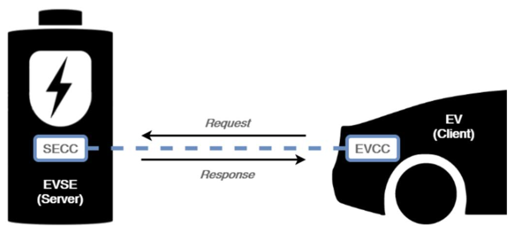
Communication controllers are responsible for the high-level communication, which controls the charging process. Communication in the ISO 15118 standard is performed in the client-server model, through request-response message pairs shown in Figure 1.
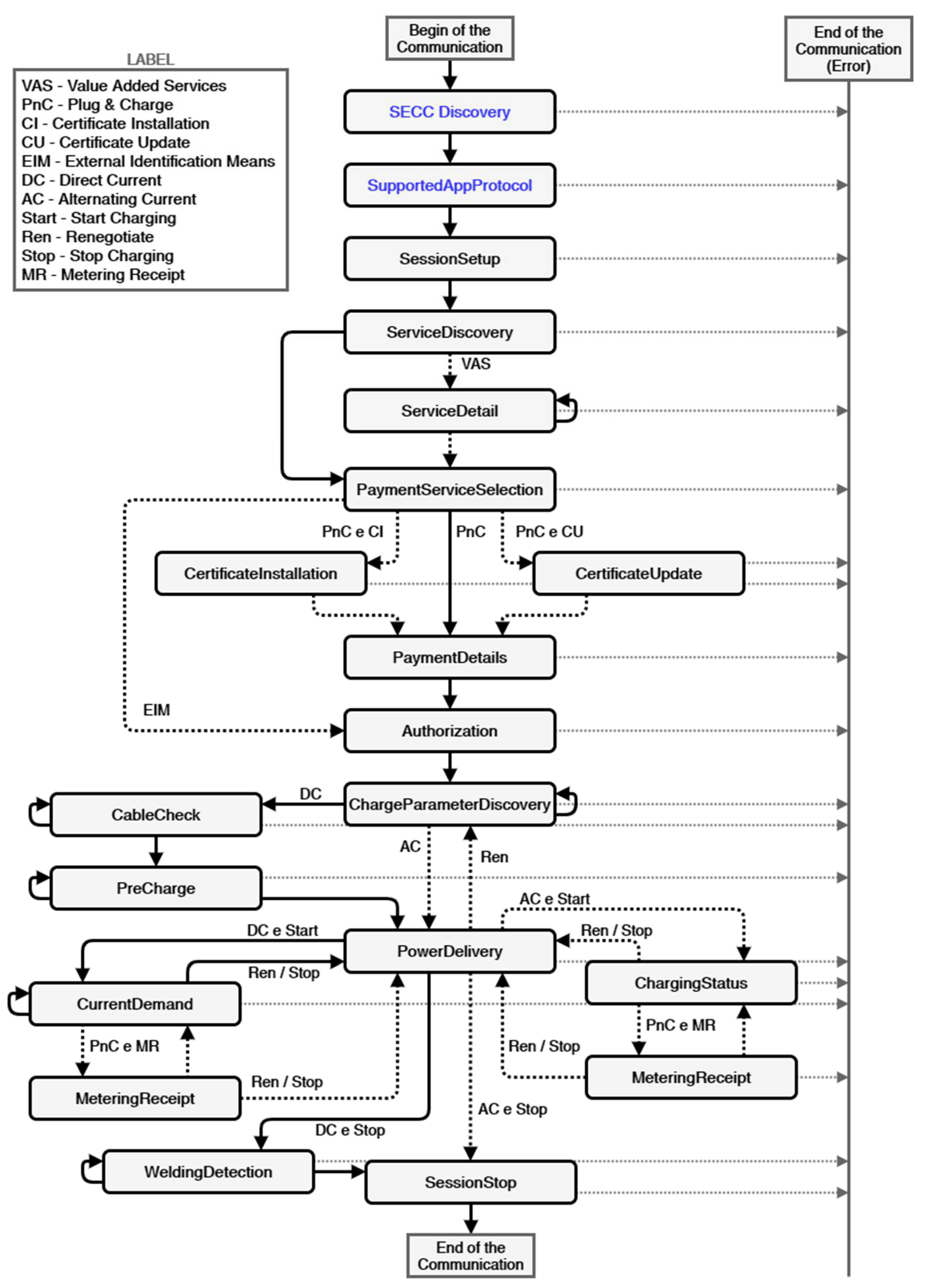
Each V2G message contains detailed information that depend on its type, in order to satisfy its own purpose. In Table 1 it is possible to observe all types of V2G messages, their associated actions and for which power transfer mode they are applied, i.e., AC or Direct Current (DC). These message types are defined in the ISO 15118 standard for conductive charging, and can be exchanged by the EVCC and SECC during a V2G communication session [11,12]. Figure 2 illustrates how the different types of V2G messages are used during a communication session.
As illustrated in Figure 2, to establish the connection for the communication session through V2G messages, firstly, two types of special messages are used: the SECCDDiscovery and the SupportedAppProtocol. Although these two messages do not belong to the group of the ISO 15118 V2G message type, it is through them that communication between controllers is initiated. In the SECCDDiscovery, the communication controllers exchange their respective IPv6 to establish an IP-based connection. In the SupportedAppProtocol, the controllers exchange information regarding the protocols supported by both. The connection via this standard is only established if both machines support the ISO 15118 communication protocol [12]

2.2. RISE V2G Open-Source Library

The RISE V2G library [13] stands out as the standard in terms of the implementation of the ISO 15118-2 communication protocol. It is an open-source implementation of the communication protocol between the EVCC and the SECC coded in JAVA language. This code offers the possibility to change configuration files, from SECC and EVCC, to simulate various implementation scenarios for digital communication during the charging process between them. These configuration files hold parameters such as the network interface through which the messages will be exchanged, the supported power transfer modes for conductive charging (AC and/or DC), and the payment options allowed, among a list of many others.
Communication controllers can be implemented through this library in two ways. The first one is using a single machine, allowing two entities (SECC and EVCC), implemented separately, to run and exchange messages. The second way is to implement SECC and EVCC on separate machines and still achieve interoperability between them. Further, in the present work communication controllers are implemented on separate machines.
In a practical charging situation where communication is set via V2G messages, while the EV is charging, the communication controllers must exchange the V2G messages referring to the charging loop during a certain period. This period must correspond to the time it takes to the EV battery to charge. Thus, the communication controllers must exchange the V2G messages referring to both the loop as to the charging time. In this library this is not the case. It only allows simulating communication during charging depending on the number of loops (i.e., the number of times the V2G messages referring to the charging loop are repeated) and not depending on the time.
Although the RISE V2G library implements communication through V2G messages according to ISO 15118, the parameters exchanged through the body of these messages remain static during the communication session. In other words, this mechanism does not allow to vary parameters like the SoC, charging currents or voltages.
Before starting the communication session, the parameters must be configured and the number of charge loops, that are intended to simulate, must be given. Then the communication session starts and ends a few seconds later, with success. Afterwards, all messages exchanged by the controllers in these seconds by the communication controllers are displayed in the console of a JAVA IDE. Observing these messages, it is possible to verify that the parameter values entered before the start of the communication session remain the same during all session. To develop a platform that would emulate the charging through the ISO 15118 communication protocol, it was necessary to develop changes to the source code of the RISE V2G library, as well as to develop additional code blocks. That process is described in the next section.

3. Charging Emulation System

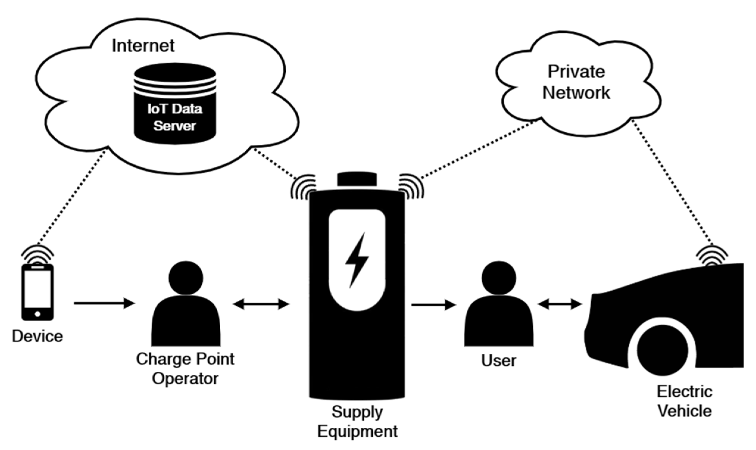
After analysing the ISO 15118 communication protocol and designing a solution for its implementation, the next step was to develop the charging emulation system between the EVSE and the EV. Figure 3 presents the general scheme of the system to be implemented, including the EV user and the Charge Point Operator (CPO).

3.1. Characterisation

The charging emulation system's main objective is to monitor and manage the main parameters exchanged during the charging process, according to the ISO 15118 digital communication protocol, using the open-source library RISE V2G.
According to ISO 15118 standard, the communication is performed through power line communication over the control pilot line. Although the RISE V2G library does not implement the physical and data link layers of the ISO 15118 standard, it uses as a resource to communicate via the network interface of the machine in which it is installed. So, in this system, communication is performed through the wireless network interface, using the Wi-Fi standard as the means of communication.
In this system there is no practical power transfer, i.e., the system only emulates de communication during the charging process between the EV and the EVSE. However, it is necessary to adopt a power transfer mode to simulate the communication through the corresponding V2G messages. Since this system was specified in the follow-up of a project, only the DC power transfer mode was chosen, because the number of parameters exchanged between the EVSE and EV in this mode is wider, which allows a better charge management. Certificates was chosen as the payment option, as it is already implemented in the RISE V2G library and offers greater security to the system. Considering this characterisation, when the system starts a communication session, it follows the V2G message flowchart represented in a black continuous line depicted in Figure 2.
This system also has the ability of sending data related to the charging process to an Internet of Things (IoT) data server. In this case, the charging data are sent to an open-source web application, dedicated to the storage and visualisation of energy data.

3.2. Architecture

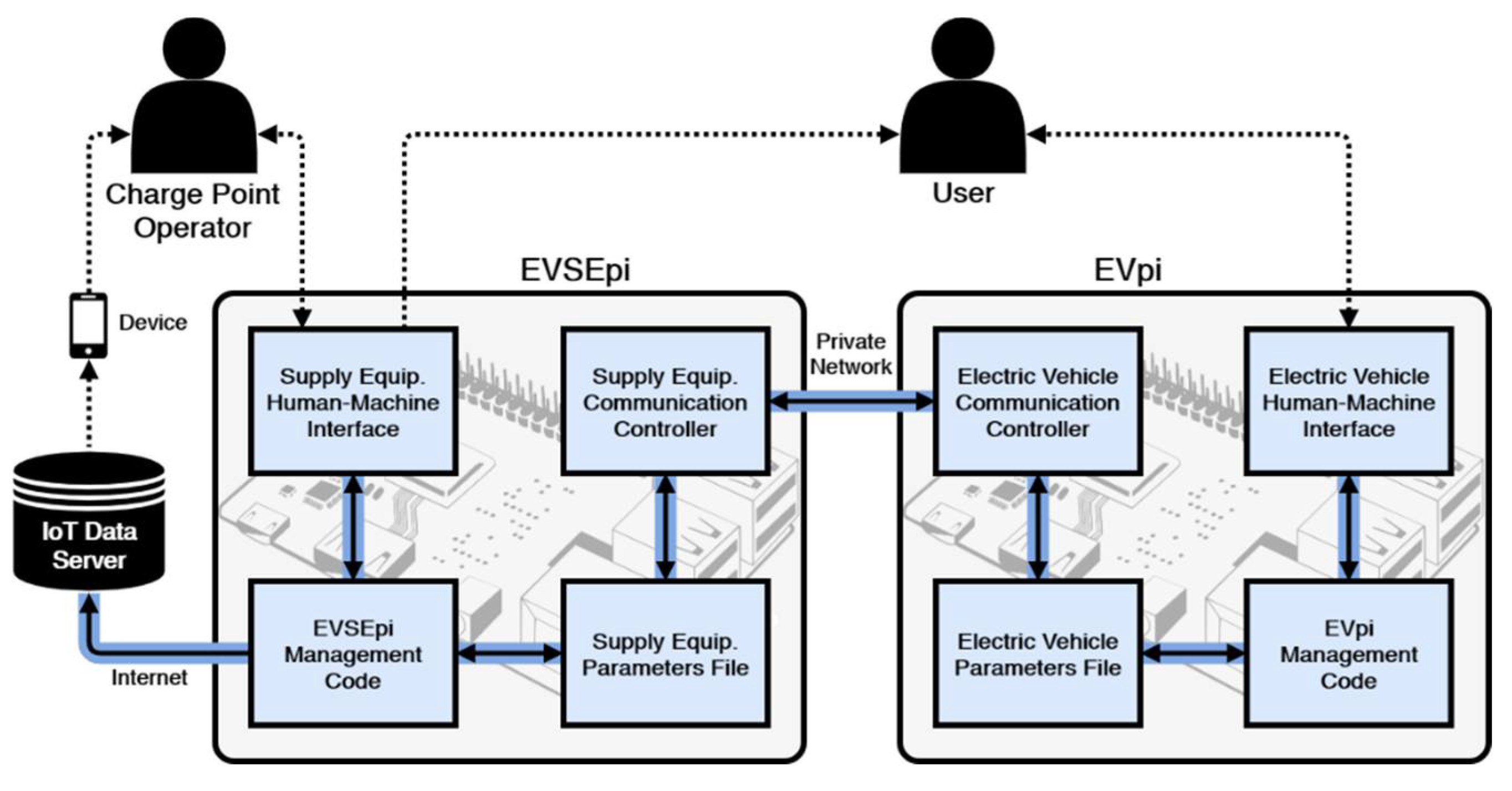
The charging emulation system is divided into two main blocks represented in Figure 4, the EVpi on the vehicle side and the EVSEpi on the supply equipment side. Each of these blocks is divided into four sub-blocks, which use the same communication principle, namely the communication controller, the parameters file, the management code, and the HMI. Both blocks were implemented on a dedicated Raspberry Pi 3 – Model B.
Communication Controllers. The communication controllers of both blocks aim to establish the communication session, through IP, to enable the dynamic exchange of charging parameters on the system. However, the RISE V2G library only allows to exchange static charge parameters. To overtake this feature of the RISE V2G library, firstly the most relevant parameters used were selected, during a communication session running on DC power transfer mode. These parameters, on library code, have been changed from static to a value that is taken from a specific line in the parameters file of the respective block. In other words, each time the communication controllers get access to a parameter, instead of directly accessing the static value of a variable in library source code, they obtain the value from a prerecorded line in the parameters file. This prerecorded line contains the value of the parameter that the communication controller wants to access, which is updated every five seconds by the management code of the respective block. These communication controllers are handled by the management code of their respective block and have an associated log file, which stores their communication records individually.
Parameters Files. The main purpose of the parameters files is to serve as an intermediary between the communication controller and the management code of the respective block. Each file has its respective parameters register list, where each parameter occupies a predefined position. Each parameter saved in this register list has its respective unit and type. This labelling is important because the communication controllers, implemented through the RISE V2G library, only allow the exchange of parameters if they are in accordance with a specific unit, and more importantly, with their specific type of variable. Thus, these parameters must keep the same name, unit, and type, on the management code side as well on the communication controller side.
In addition to the ISO 15118 communication protocol parameters, the parameters register list file also contains local interaction indicators (flags) so that the communication controller and the management code of the same block can be synchronised (more on this later). All flags are defined as boolean type, with initial value set to “False”.
Management Codes. The management codes were developed in the JAVA programming language and their main objectives are to control the charging process, the communication controller and the information processed on the HMI of the respective block. Each management code is implemented according to its respective finite state machine, where each state is responsible for a certain set of tasks of the respective code.
One of the main objectives of the EVpi management code is to control the charging process of the EV battery. This approach allows to define batteries with different characteristics in the EVpi management code. In this paper, a virtual Li-ion battery was implemented which only helps emulate the typical functioning of an EV charging process, generating the corresponding curves, and bringing the developed system closer to a real charging process. Nonetheless, some influencing behaviours such as temperature and cell balance were set aside.
The charging process of the EV lithium-ion virtual battery, applies both the Constant Current (CC) and Constant Voltage (CV) charging techniques, known as the CC-CV strategy. The CC-CV strategy consists of dividing the charging process into the former two charging techniques [14,15].
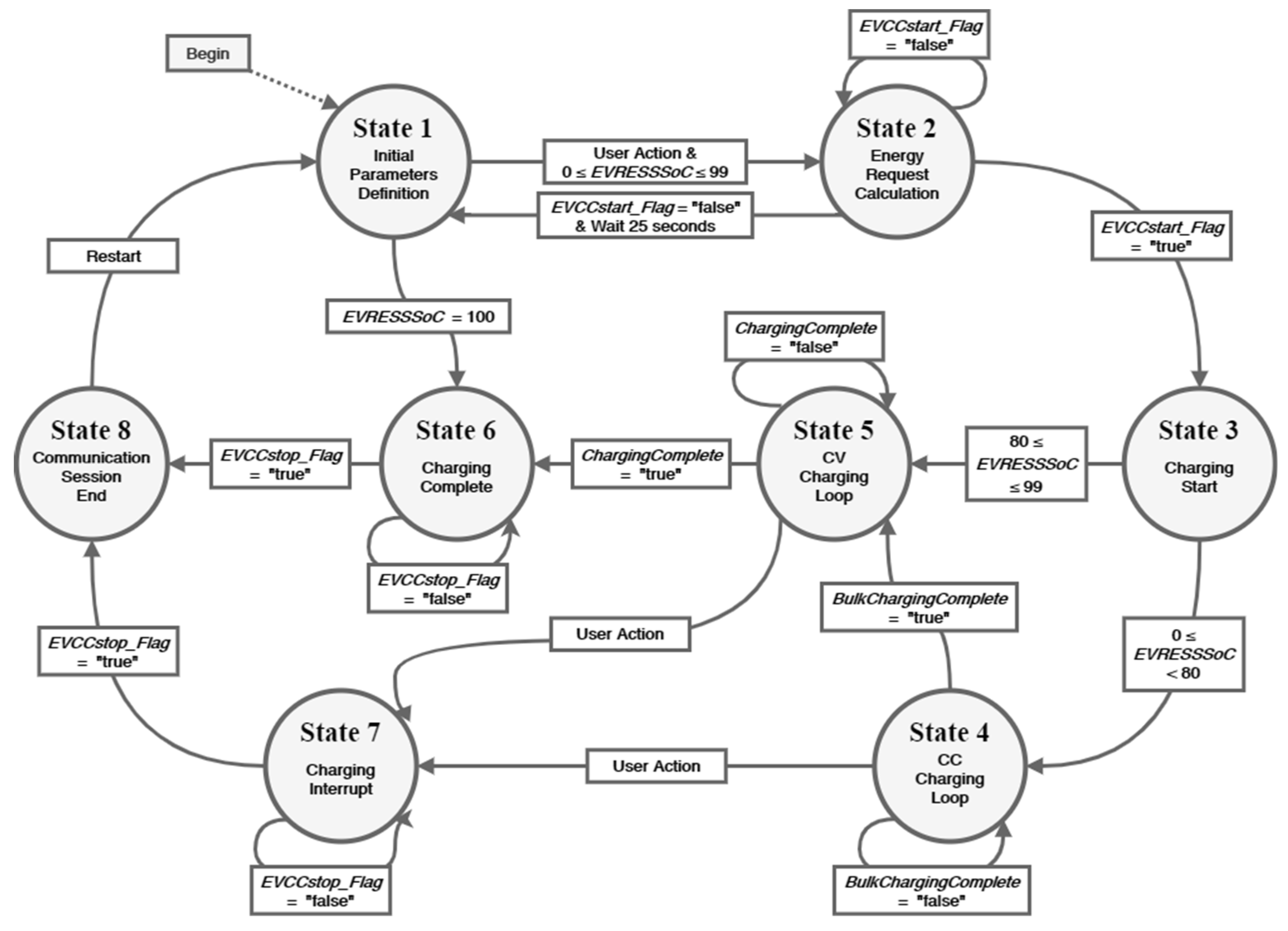
The EVpi management code implements a finite state machine, consisting of eight states, as shown in the diagram represented in Figure 5. Next, the states will be described.
EVpi State 1. Named Initial Parameters Definition, this initial state is when the vehicle user starts by defining, through the EV HMI, the limits of the current and voltage as supported by the vehicle. The user can also define with which state of charge the EV starts the charging emulation. The EVpi management code, in this state, is only responsible for accepting these parameters values. To obtain a more realistic charge emulation these values should be introduced according to the values of the virtual battery implemented in the management code. After having the initial parameters defined, the user promotes the EVpi management code to change its status through interaction with the EV HMI. If the vehicle battery is fully charged, the EVpi management code changes to state 6. If the vehicle battery needs charging, the EVpi management code changes to state 2.
EVpi State 2. Named Energy Request Calculation, the EVpi management code calculates the amount of energy required to charge the vehicle to 100% SoC, and then gives the order to the EVCC to start the communication session. Through the EVCC start flag, the management code checks whether the EVCC has been able to establish the communication session with the SECC. In case of success, the EVpi management code changes to state 3. After 25 seconds, if the EVpi management code does not establish communication, it goes back to state 1.
EVpi State 3. Named Charging Start, in this state the charging parameters are changed before the charge of EV takes place. In other words, the EVpi management code sends the EV parameters to its own communication controller and receives the EVSE parameters from it. The parameters sent by the EVCC are: (1) The EVCC identifier, (2) the maximum current and voltage limits supported by the EV and (3) the EV SoC. The parameters received by the EVCC are: (1) The communication session identifier, (2) the EVSE identifier, (3) the maximum current, voltage and power limits supported by the EVSE, and (4) the minimum current and voltage limits supported by the EVSE. After this exchange, current, voltage and power limits are established for charging, to not compromise the EV or the supply equipment. Once these limits are established, charging emulation is started by sending the ‘Start’ value through the charge progress parameter. Thus, there is a change from state 3 to state 4 if the SoC of the vehicle is below 80%, or to state 5 if the SoC is above or equal to 80%. This change of state depending on the SoC is due different charging techniques are used in each of the next states.
EVpi States 4 and 5. Named CC Charging Loop and CV Charging Loop, respectively, these states represent the charging loops according to the charging techniques. In these states, the EVpi management code sets the target current and voltage values to charge the EV battery according to the respective charging technique. The target current and voltage values are sent to the SECC, via the EVCC, so that the supply equipment can meet the vehicle's needs. In these states, the values of the remaining time to full charge and the EV SoC are also established, considering the values of the EVSE present current and voltage. While the EVpi management code remains in one of these two states, the parameters mentioned above are constantly changing and updating, with a periodicity of 5 seconds. The transition of these states can be performed in two different ways, which are through the EV user's action using the vehicle's HMI or by checking the EV SoC. When using user action, both states change to state 7. This user action results from pressing the stop button on the EV HMI. On the other hand, when checking the EV SoC, there are different situations for each of these two states. In state 4 when the vehicle SoC reaches 80%, the value of the bulk (or fast) charge complete indicator is changed to ‘true’ and the EVpi management code goes to state 5. This is due the charging technique is changed from constant current to constant voltage. In state 5 when the vehicle SoC reaches 100%, the full charge complete indicator value is changed to ‘true’ and the EVpi management code goes to state 6.
EVpi States 6 and 7. Named Charging Complete and Charging Interrupt, respectively, these states represent the last 5 second charging loop and consequently the stop of charging. In state 6 the stop is performed due to the fully charged status of the EV, while in state 7 the stop is due to the interruption of charging process by the vehicle user. In these states, the EVpi management code is responsible for setting the EV target current and voltage values to zero, as well as the parameter charge progress value to 'Stop'. Through the charge progress parameter, the EVCC informs the SECC that a charging stop has been requested, thus ending the exchange of the V2G message related to the charging loop and starting the exchange of V2G messages responsible for the end of communication session. Once the communication session is ended, the EVpi management code sets the EVCC end flag with the value ‘true’ and goes to state 8.
EVpi State 8. Named Communication Session End, the main task of the EVpi management code here is to update all its variables to their initial values and terminate processes that were started during the previous communication session, so that a new communication session can be started. After this update, the management code waits 10 seconds and go to state 1 (i.e., transits to its initial state), where a new charge emulation can be started.
Moving on to the EVSEpi management code, its main objective is to manage the EVSE charging process. To do this, it is necessary to have access to the voltage and current limit values. Under real circumstances, these values are limited by the electrical grid, or by the battery system (in case there is no connection to the electrical grid). In this charge emulator system, these limits are established by the CPO, through the EVSE HMI. The EVSEpi management code is also responsible for calculating the energy transferred during each charge and applying the appropriate energy tariff, as well as sending the information about the charges for an IoT data server.
The IoT data server used in this system is Emoncms [16], where it is possible to generate graphs of the charging parameters over time. These temporal graphs are extremely important for the CPO, as they can monitor all the information that was and is being processed during charges.
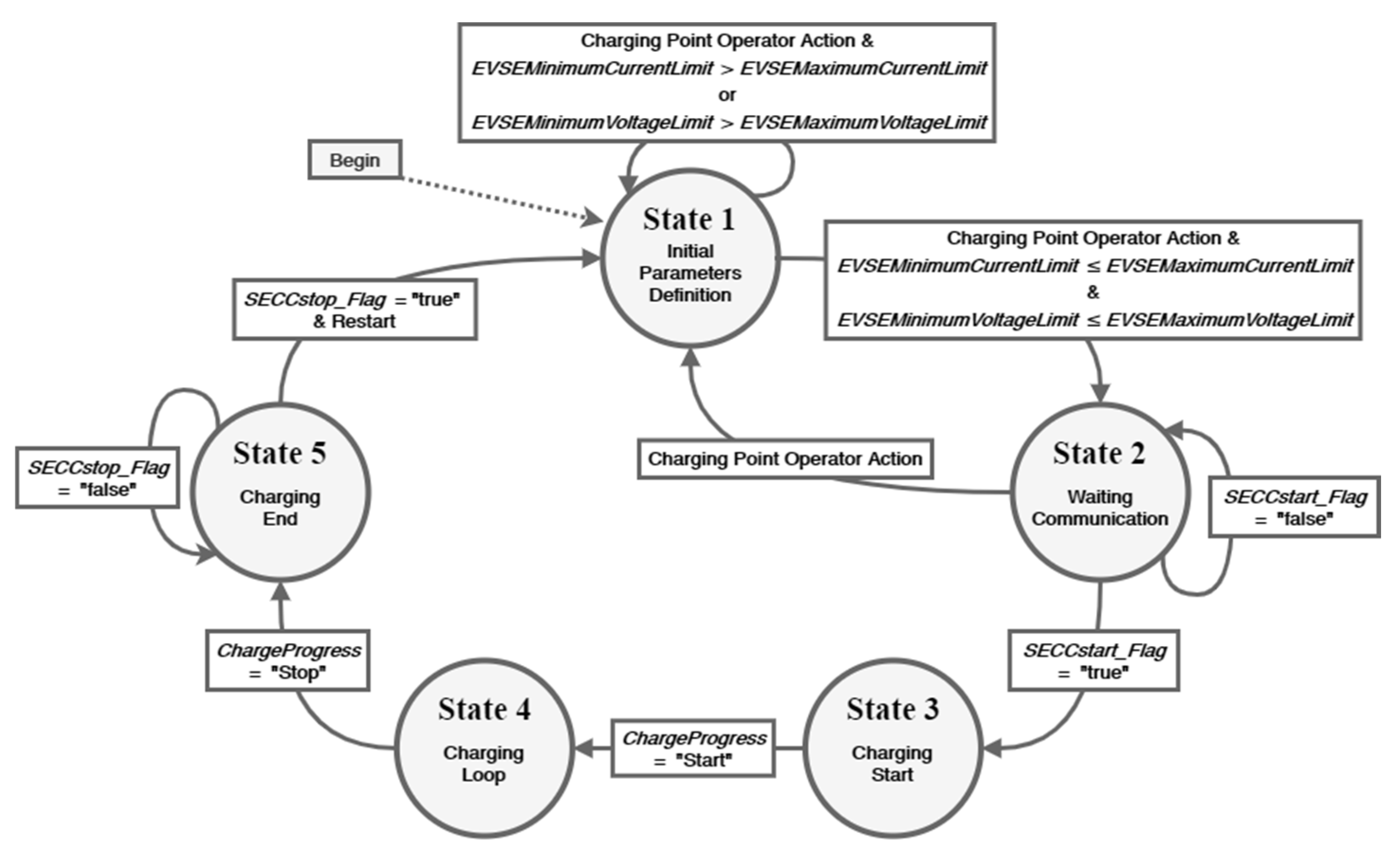
The EVSEpi management code implements an finite state machine consisting of 5 states and as shown in the diagram in Figure 6. These states are described next.
EVSEpi State 1. Named Initial Parameters Definition, in this initial state the CPO starts by defining, through the supply equipment HMI, the values of the maximum and minimum current and voltage limits supported by the EVSE. Once the initial parameters have been defined, and after the operator gives an indication through the human-machine interface, the EVSEpi management code checks the values entered before changing his status. Whenever the values of the defined minimum limits are greater than the values of the defined maximum limits, EVSEpi remains in the first state and requests a new initial definition of parameters to the CPO. Otherwise, the EVSEpi management code goes to state 2.
EVSEpi State 2. Named Waiting Communication, in this state the EVSEpi management code activates the SECC so that it waits for a connection with the EVCC. If a new communication session is detected, the SECC informs the EVSEpi management code through the “true” value of SECC start flag and goes to state 3. The EVSEpi management code can be in this second state for an indefinite period of time if a new communication session is not established. Then the CPO has the ability of making the management code return to its initial state (state 1), through a stop button present in EVSE HMI.
EVSEpi State 3. Named Charging Start, this state uses the same principle as EVpi state 3 where the charging parameters are exchanged before the charging takes place. So, in this state, the EVSEpi management code sends the supply equipment parameters to its communication controller and receives the vehicle parameters from it. The parameters sent by the SECC are: (1) The communication session identifier, (2) the EVSE identifier, (3) the maximum current, voltage and power limits supported by the EVSE and (4) the minimum current and voltage limits supported by the EVSE. The parameters received by the SECC are: (1) The EVCC, (2) the maximum current and voltage limits supported by the EV and (3) the EV SoC. Then, the current, voltage and power limits for charging are established, as well as the hourly period of the tariff and its associated cost. After that, the EVSEpi management code sends the processed information to the IoT data server. After accomplishing this set of tasks, the EVSEpi management code checks the charge progress parameter value. If the value is 'start', the charge emulation begins and, consequently, the exchange of the V2G message related to the charging loop, which leads to the transition to state 4.
EVSEpi State 4. Named Charging loop, in this state the EVSEpi management code gets the values of the remaining time to reach full charge, the target current and voltage for charging the EV and the EV SoC from the vehicle. The code then establishes the current values of the EVSE electrical current and voltage considering the availability of the electrical grid or renewable generation system plus batteries. In this state, the EVSEpi management code also sets up parameters values that are not part of the ISO 15118 communication protocol, such as the EVSE present power, the charge energy, and the charge energy cost. These parameters are set and updated considering the duration of the charging loop (5 seconds). In state 4, the EVSEpi management code is still responsible for sending the charge information to the IoT data server. This information is sent with a periodicity of 1 minute (i.e., every 12 charging loops). The EVSEpi management code goes to the next state (state 5) only when charging ends, that is, when the charge progress parameter shows the value 'Stop'.
EVSEpi State 5. In this state, named Charging End, the EVSEpi management code ensures that the EVSE present current, voltage and power values are zero. Thereafter, the connection between the communication controllers is finished and the final information about the charge is sent for the last time to the IoT data server. Finally, the EVSEpi management code checks the value of the SECC's end flag to know if the communication session has ceased. Once the communication session is finished, it resets the local variables, waits for 10 seconds, and returns to its initial state (state 1).
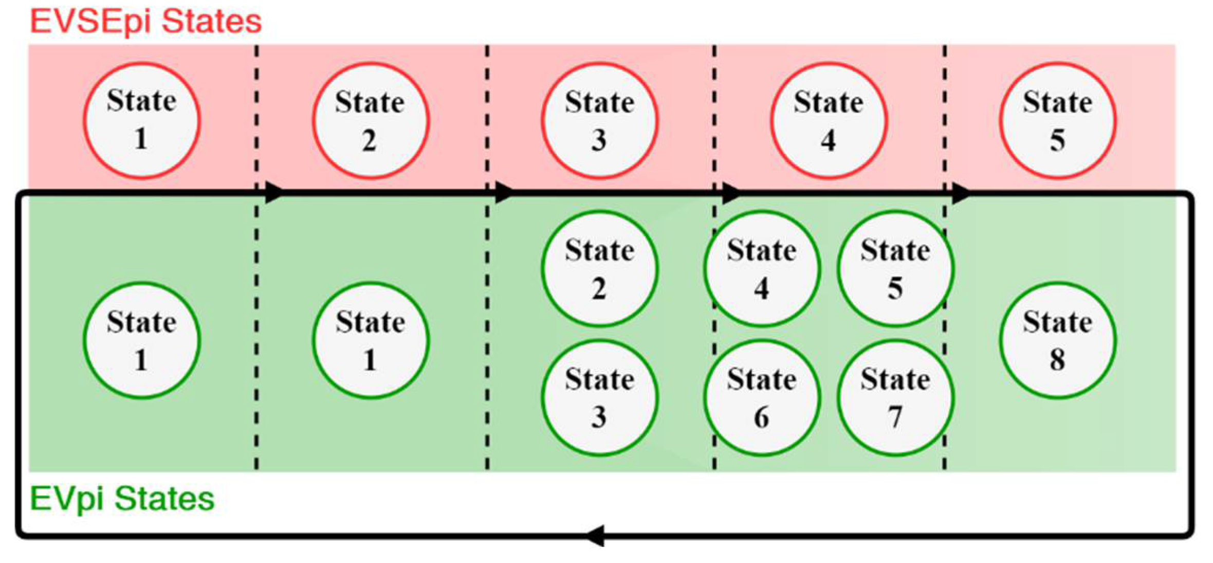
Figure 7 illustrates how the states of each block (EVpi and EVSEpi) are combined to make the implemented system works. During system operation, each EVSEpi state is related to one or more EVpi states, however, it can only be conjugated to one of these related states at one time instant. For example, state 4 of EVSEpi is related to states 4, 5, 6 and 7, but for the system to operate it can only be combined with one of these four states. So, in the case where the EV charges according to the CC charging loop technique, while EVpi must be set to state 4 EVSEpi will be set on state 4.
It should be noted that for the system to operate correctly, the EVSEpi management code must be in state 2 before the EVpi management code goes from state 1 to state 2, as shown in the diagram in Figure 7. This rule applies for every state transition.
Human-Machine Interfaces. The HMI are intended to allow defining limit values of voltage and current supported by each machine (EV and EVSE) before the communication session is started. This way, the system allows different charging scenarios to be emulated. These interfaces also provide the information about the EV charging that is updated every 5 seconds. Its respective source codes were developed in JAVA programming language, with the aid of the graphical user interface tool Swing of Netbeans IDE and are controlled by the respective management codes. Next, these interfaces are described according to their block (EVpi and EVSEpi).
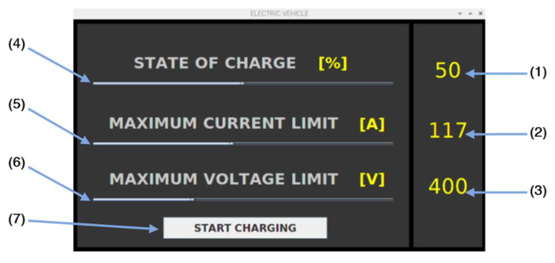
Electric Vehicle Human-Machine Interface. In its initial appearance, the EV HMI presents the initial parameterisation screen (Figure 8) which corresponds to the behavior of state 1 of the EVpi management code.
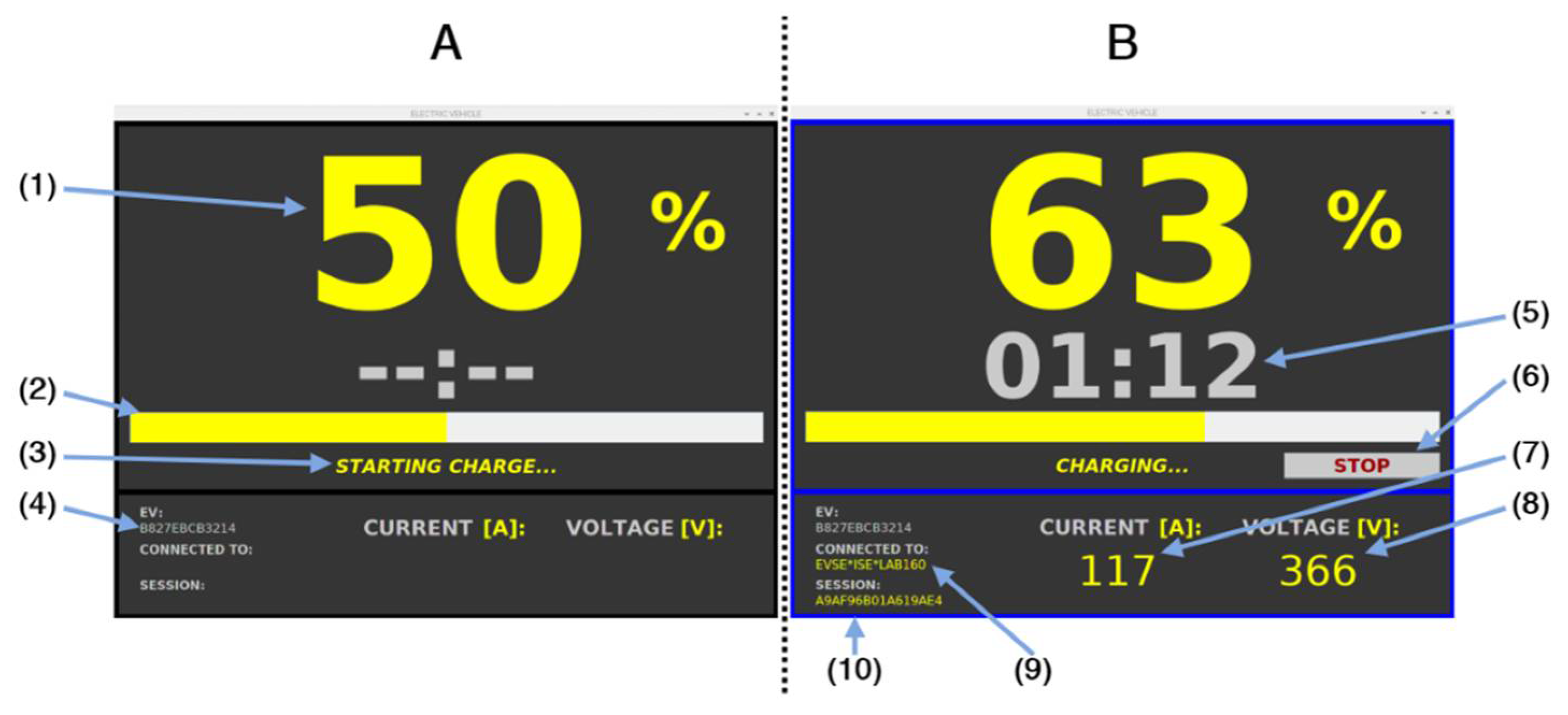
When button (7) is pressed (Figure 8), the EV HMI goes to a new screen, the EV charging screen (Figure 9). This screen is used to follow all the behaviours of the EVpi management code states except the first one. From there it is possible to observe information related to the charging status, as well as information related to the communication session status.
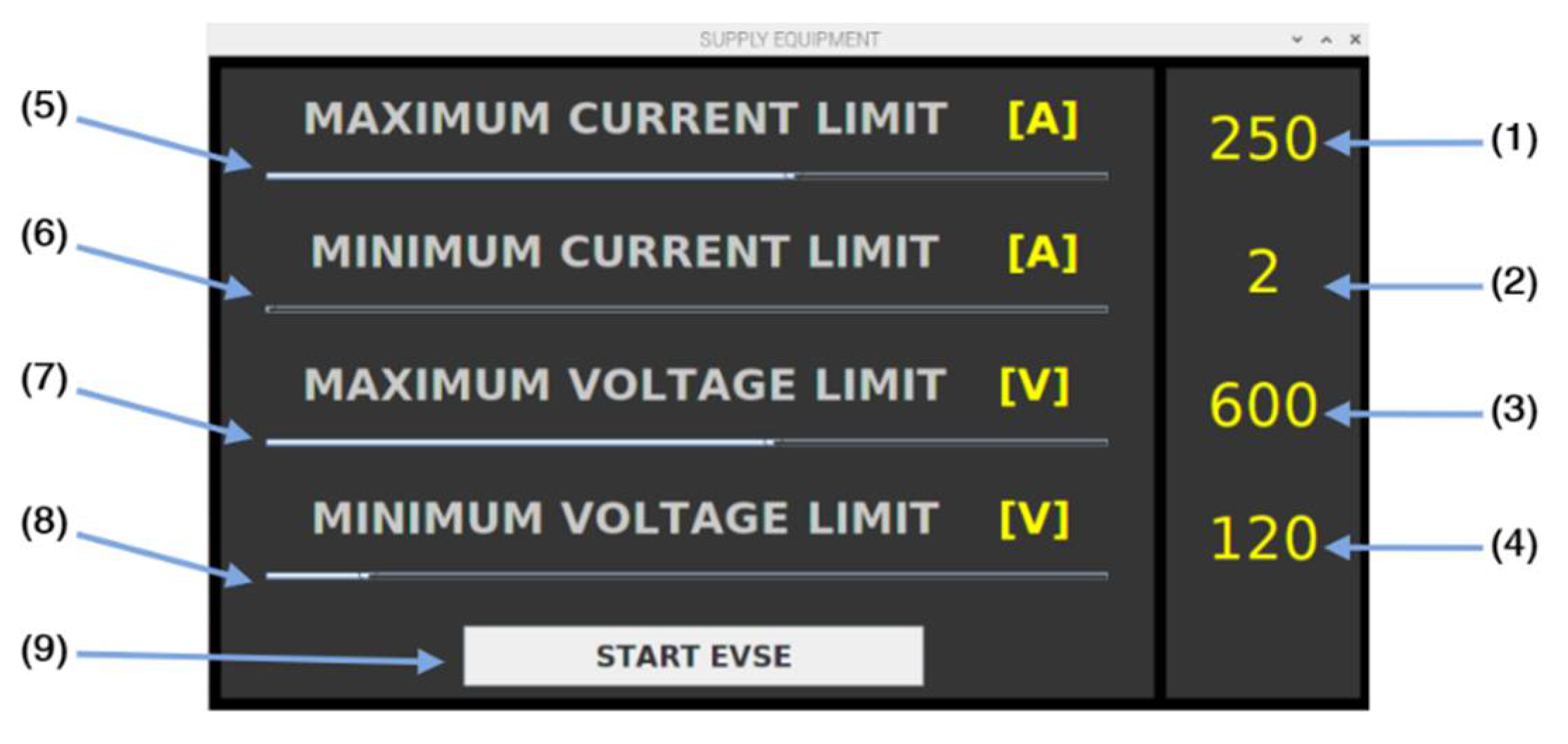
Charging Point Human-Machine Interface. The supply equipment HMI uses the same principle as the EV’s but dedicated to the charging station. Thus, in its initial appearance, this interface presents the EVSE initial parameterisation screen (Figure 10).
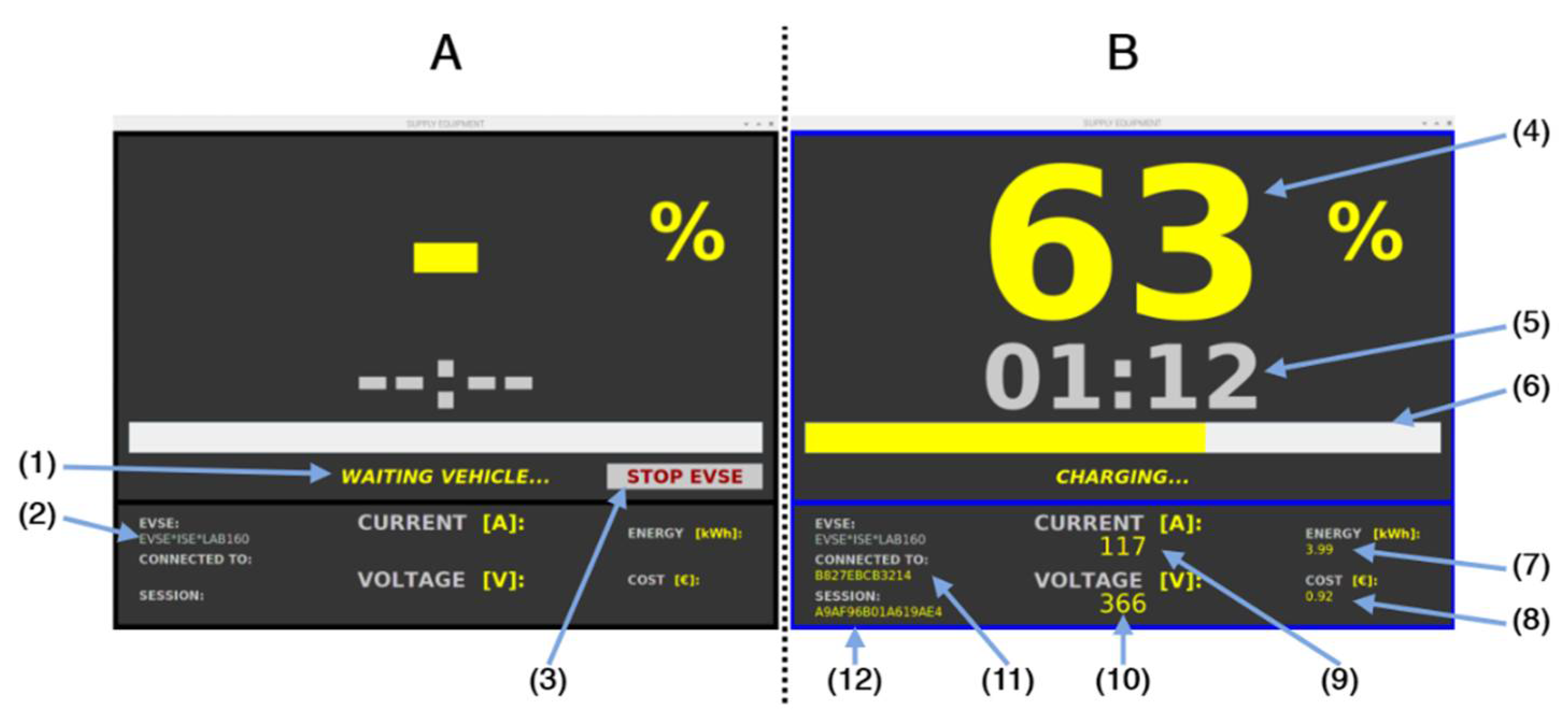
After this information is sent, the EVSE's HMI goes to its charging screen. The charging screen is used to monitor all behaviours of the EVSEpi management code states, except for the first one. Alternatively, it is possible to observe information about the charging, as well as the communication session (Figure 11). But unlike the EV HMI charging screen, the EVSE HMI charging screen in this first phase is made available before the communication session starts.
3.3. Task Scheduling Algorithm

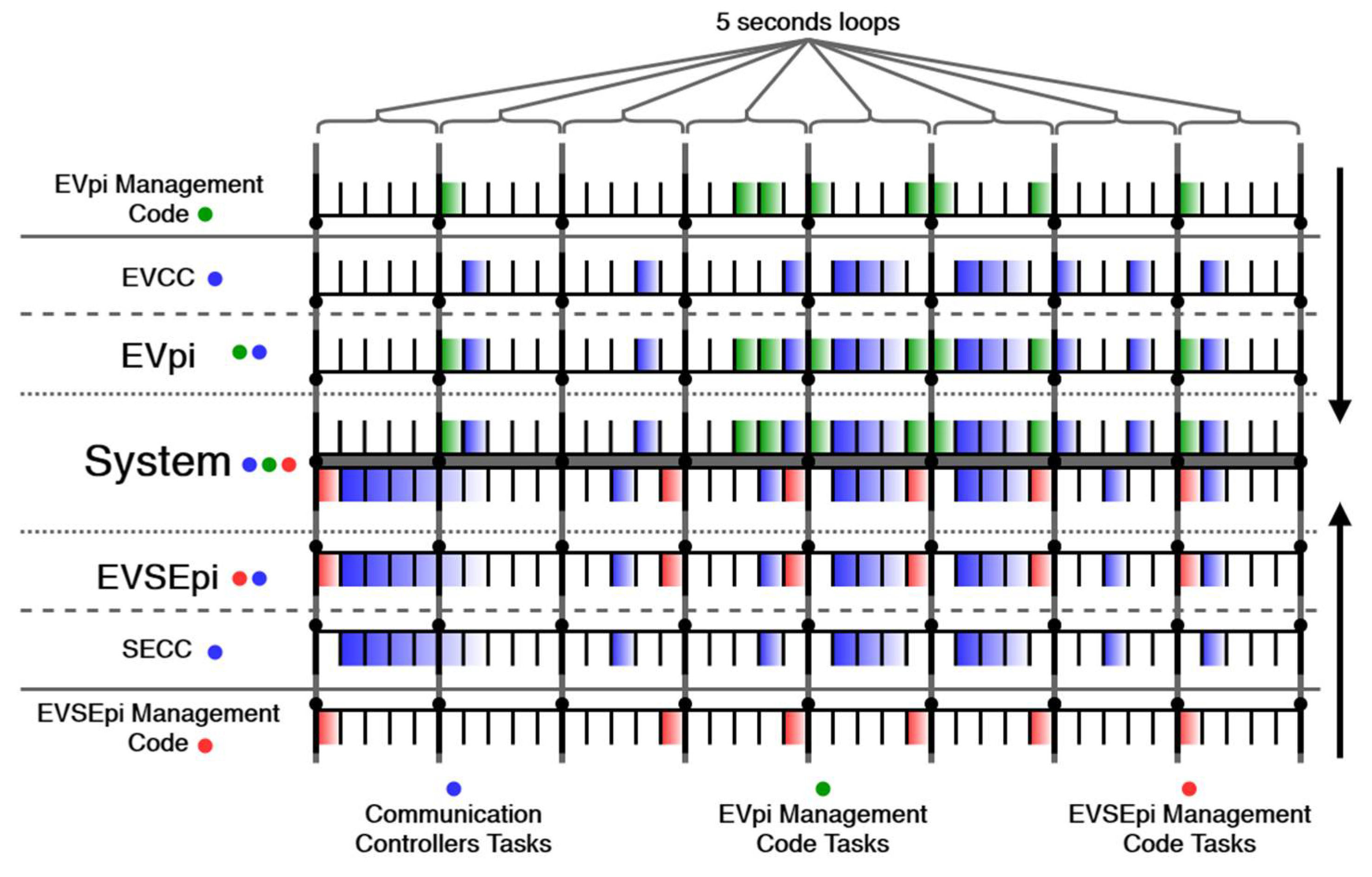
The charging emulation system also implements a task scheduling algorithm, so that the entire information can flow in a synchronised way and without failures or collisions. This algorithm not only allows the system to become lighter at the processing level, but also avoids access collisions to the parameters file of each block. The tasks performed in the system are composed by the tasks performed by EVpi and EVSEpi. The tasks performed by EVpi are composed of the tasks performed by the EVpi management code and the EVCC. The tasks performed by EVSEpi are composed of the tasks performed by the EVSEpi management code and the SECC. Figure 12 presents the task scheduling at both extremes.
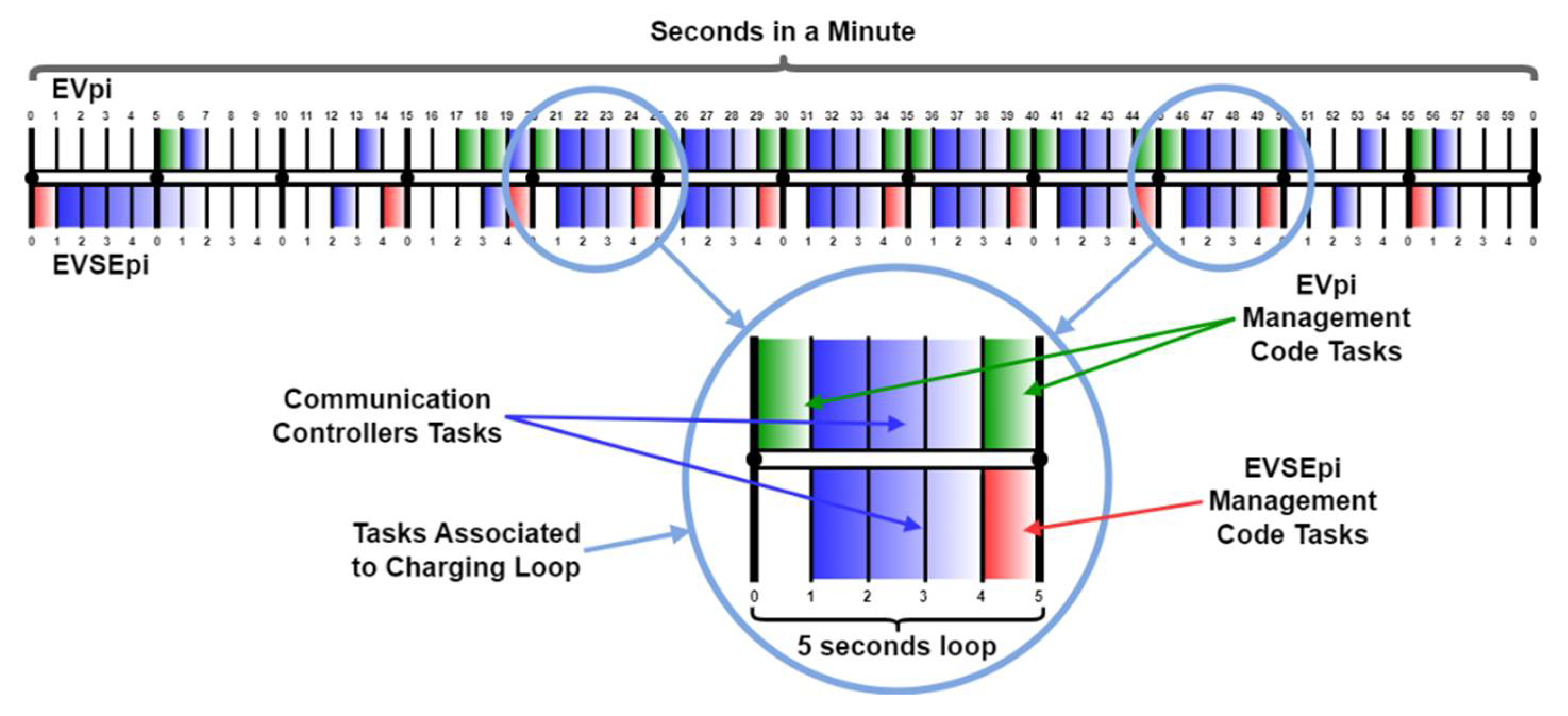
This algorithm is based on 5 seconds loops, where each second corresponds to a set of tasks that do not compromise the information flow, as can be seen in Figure 13.
Task sets divided by 1 second intervals, usually, have a running time of less than 1 second, yet a full second interval is reserved for each set, thus lightening the system. Its scaling at intervals along the 5 seconds loop is performed whenever the clock seconds are a multiple of 5. For example, if a given task runs in the time interval [0 to 1], the algorithm performs this same task when the seconds of the minute are multiples of 5, i.e., this task can be started in seconds 0, 5, 10, 15, 20, 25, etc… as can be followed in Figure 14.
Through this timestamp, the EVCC adopts the same time as the SECC, making it possible to implement synchronisation during the communication session.
The use of the 5 seconds loops for the algorithm was performed based on the tasks that the blocks can perform without compromising the system operability. Since each block is implemented in a Raspberry Pi 3 – Model B microcomputer, and the controllers communicate through wireless networks, 3 seconds were reserved for communication purposes only. The remaining 2 seconds, out of the 5 seconds of the loop, were reserved for tasks in the management code of each block, such as analysing and updating charging parameters and updating its respective HMI.
On the other hand, one of the scenarios in the development of this communication system was the integration with a charging system that allows generation of renewable energy. Since the energy arising from the renewable generation is too intermittent, it is necessary to transmit viable information, i.e., the information about the energy transmitted between the communication controllers of the system must follow the energy that is generated instantly by the RES. Only in this way are avoided exceptional consumptions from the grid, with only the energy generated by the renewable source being consumed by the charging.

4. Resulting System and Demand Response Evaluation

This section describes the developed ISO 15118 EVSE and EV emulator system and evaluates its capability to support demand response when conjugated with a photovoltaic renewable energy source.

4.1. ISO 15118 EVSE and EV Emulation Platform

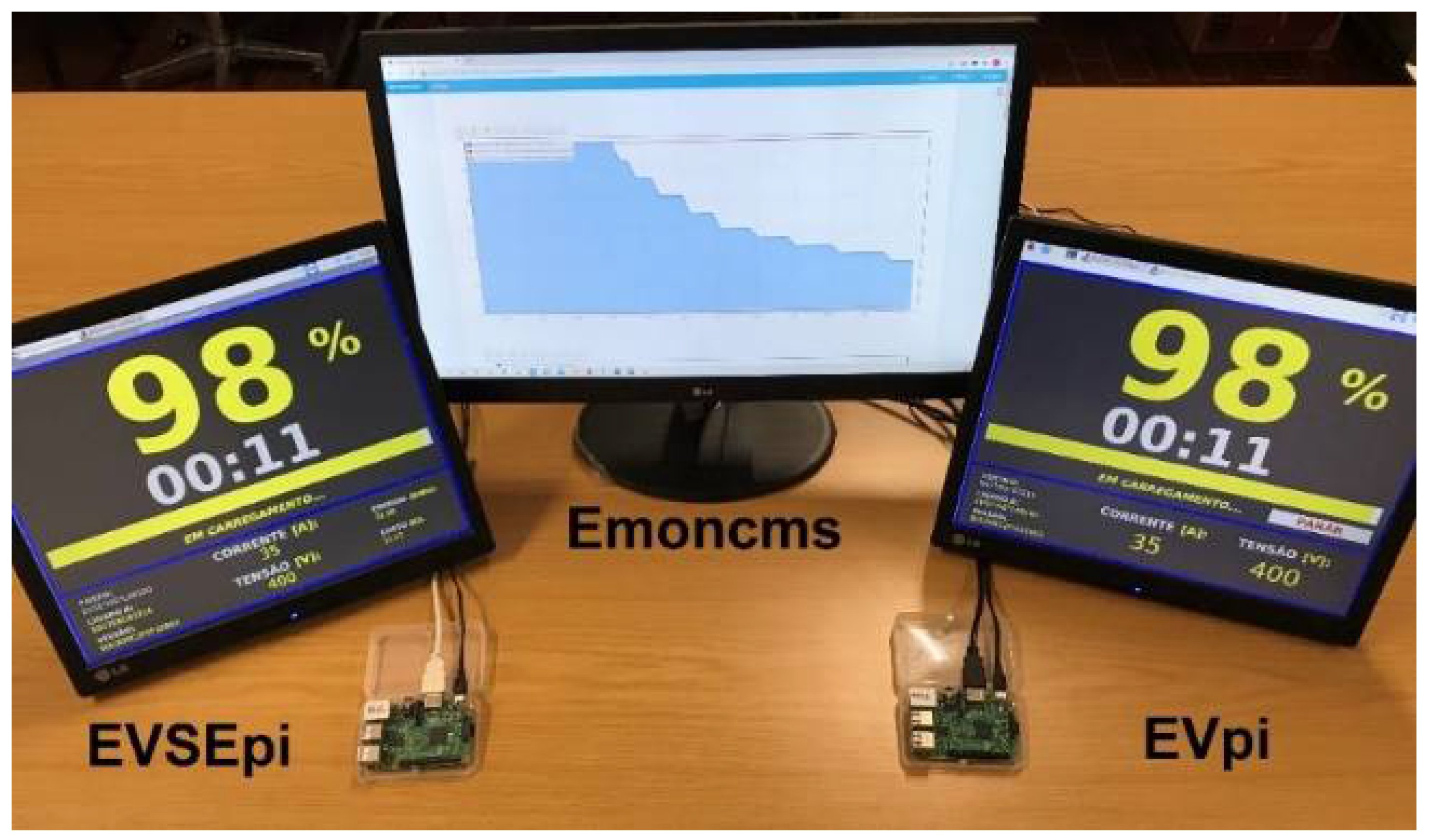
In Figure 15, it is possible to observe the final product of the charging emulation system, resulting from the architecture presented above.
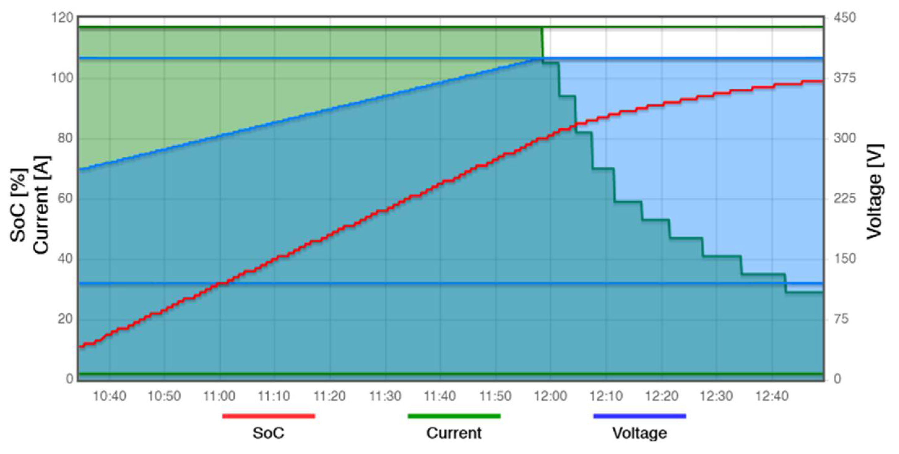
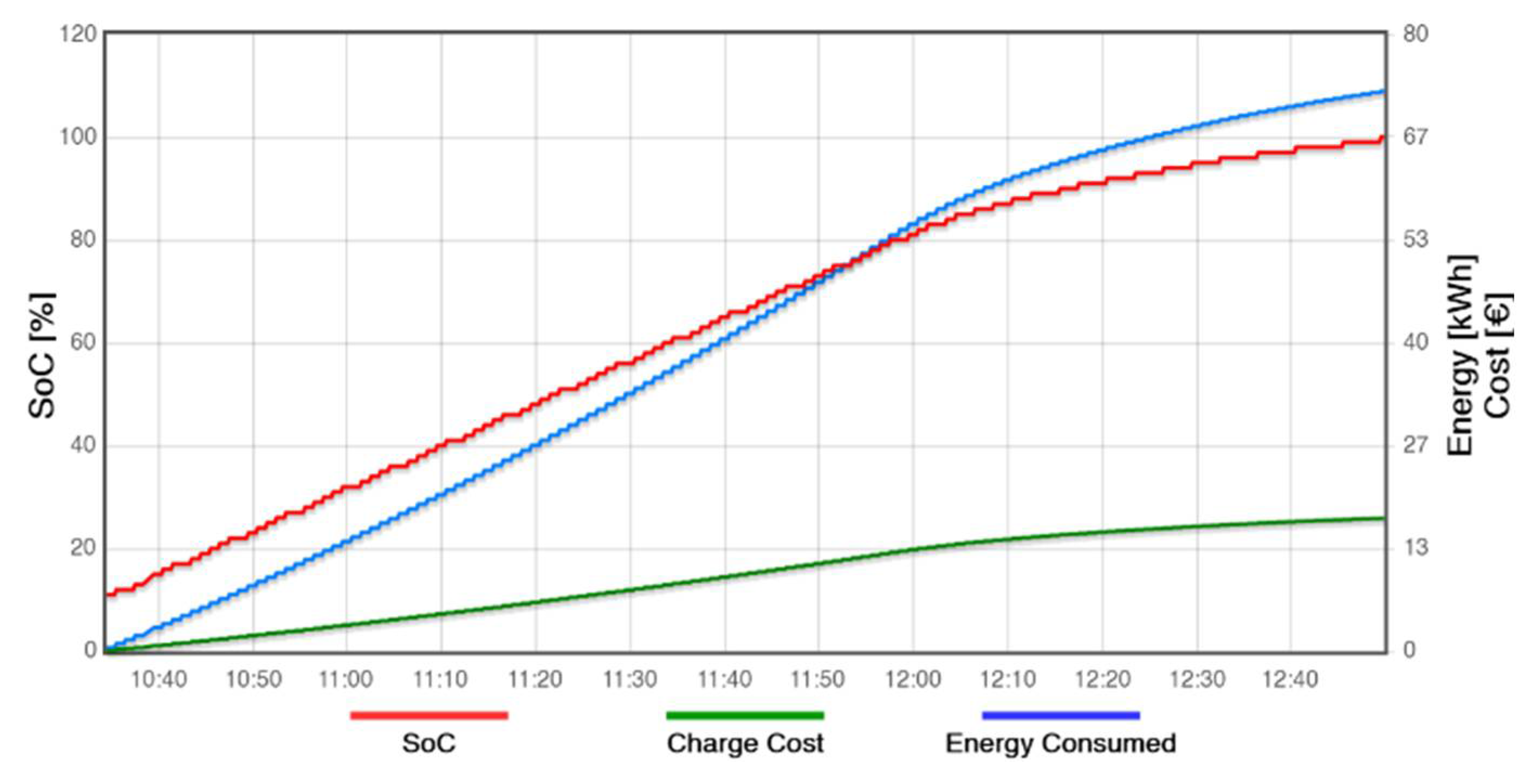
The information presented on graphs in the data server is based on the initial parameters of the EV and EVSE, and the time period in which the charge emulation is performed. For each charge emulation, a temporal graph is created in the IoT data server, with information from the EV and EVSE. This information is sent to the server every 1 minute by the EVSE, which makes it possible to observe the dynamism of the ISO 15118 communication protocol parameters throughout the charging emulation. Next, two of these graphs are presented (Figure 18 and Figure 19), as an example of running a simulation where the initial conditions of emulation are given in Table 2.
The graph in Figure 16 illustrates the behaviour of current and voltage during the charging emulation.
Figure 16. Charging Graph (current and voltage behaviour). The red line represents the SoC in percentage, the green line represents the current of charging in amperes, and the blue line represents the voltage of charging in volts. The top and bottom straight green lines represent the maximum and minimum current that the charging process can reach. The top and bottom straight blue lines represent the maximum and minimum voltage that the charging process can reach.
Preprints 105477 g016
The graph in Figure 17 illustrates the behaviour of energy consumed and its associated cost during the charging emulation for the same scenario.
Figure 17. Charging Graph (Energy and Cost Behaviour). The red line represents the SoC in percentage, the green line represents the charge cost in Euros, and the blue line represents the energy consumed during the charging in kilowatts hour.
Preprints 105477 g017
With the information in this graph, it is possible to verify that the EV starts the charging emulation with a SoC of 10%, around 10:34h and ends it, with a SoC of 100%, around 12:49h. During these 2 hours and 15 minutes, the EV charges 90% of its battery, where approximately 72.7 kWh were transferred. This emulation was performed in a time period in which electricity has its highest cost (peak hours), so the 72.7 kWh transferred from the electricity grid to the EV battery results in a charging cost of €17.30 according to the tariff applied at the EVSE.

4.2. Evaluation of the Responsiveness of the System for Demand Response Purposes

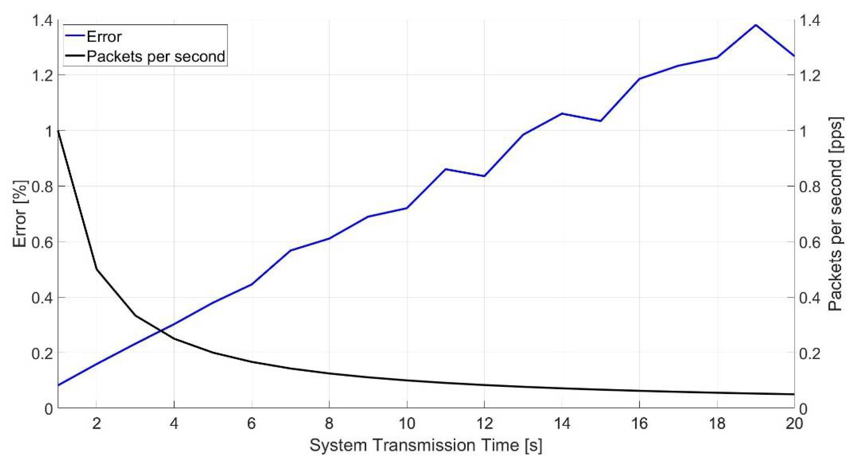
In this section we evaluate the responsiveness of the performed system in a Demand Response scenario, according with the periodicity between SECC and EVCC transmissions. In the development of the system a periodicity of 5 seconds was selected, however it is important to assess of this value is adequate in terms of: (i) difference between charging and generation powers and (ii) number of packets per second.
In order to perform this assessment, we considered an energy generation dataset, of a high-definition sampling from a photovoltaic unit, with the power per square meter collected by a unit of photovoltaic panels during nearly 11 hours of daily light, in one day [17]. The dataset selected considers a cloudy day with high intermittency levels.
In order to evaluate the mismatch between generation levels and charging levels we simulated the responsiveness of the system with different communication periods between SECC and EVCC. We considered that the photovoltaic generation levels are transmitted to the SECC every 100 milliseconds. We then varied the transmission periodicity between controllers, from 1 to 20 seconds, and computed the percentual error between generation and charging powers, and the number of packets per second that would be required in each case.
Figure 18 shows the associated results.
Figure 18. Communication System Error. The blue line represents the percentage of error associated with the system transmission time. The black line represents the rate of packets per second associated with the system transmission time.
Preprints 105477 g018
In this graph it is possible to conclude that the 5 seconds periodicity communication between the controllers used in the task management algorithm, results in a low associated error between generation and charging levels (0.3798%). It is also possible to conclude that the rate of packets per second is relatively low (0.2 packets per second).
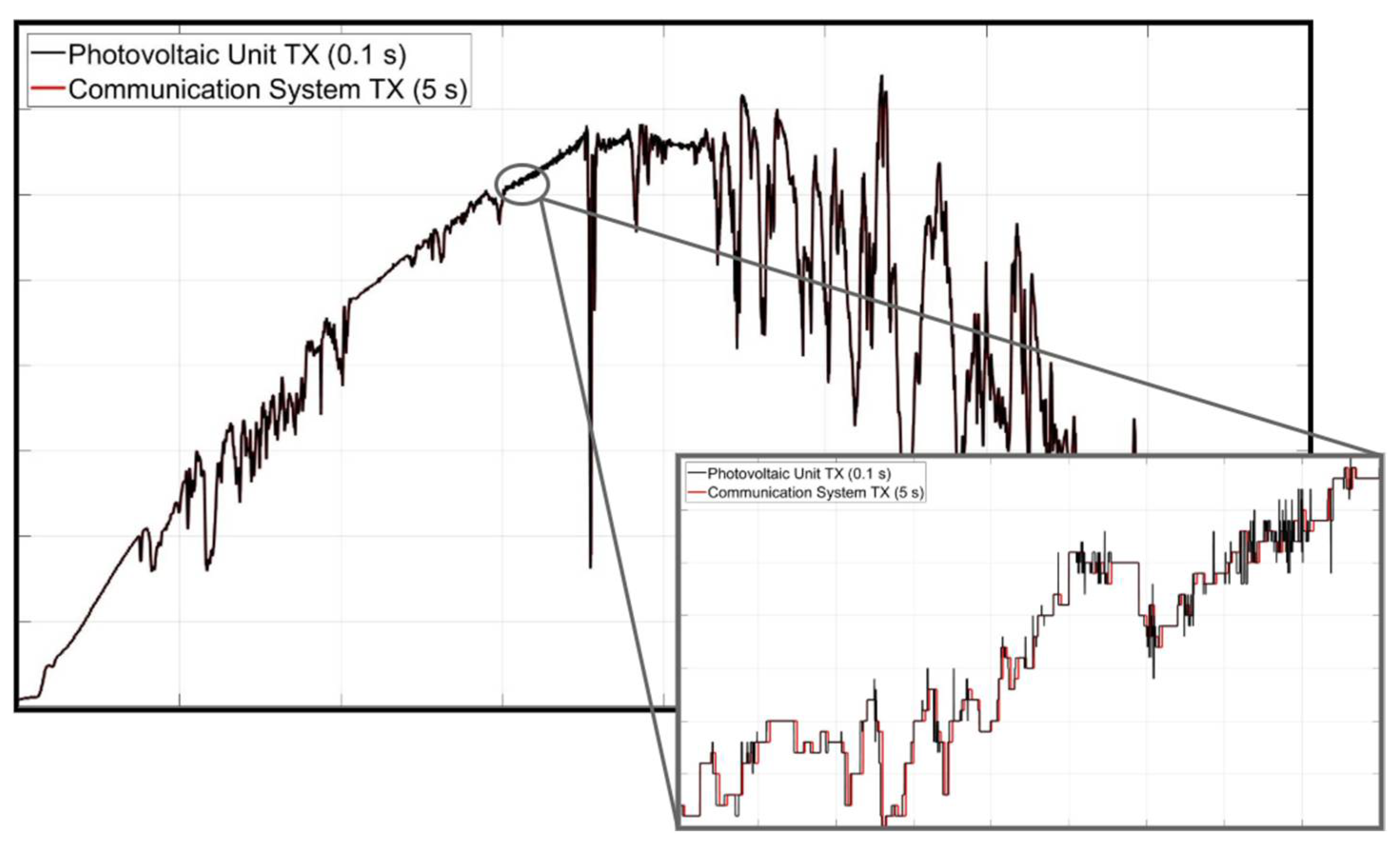
Considering a periodicity of communications between SECC and EVCC of 5 seconds Figure 19 plots the difference between generation and charging levels. It can be seen that the values transmitted by the photovoltaic panel unit and the values transmitted between the communication controllers are very close throughout the daily sample. In light of these results, the utilization of the 5 seconds between transmissions in the setup for the task scheduling algorithm is justified.
Figure 19. Photovoltaic Unit and System Communication deviation Samplings. The black line represents the photovoltaic unit transmission values, and the red lines represents the communication system transmission values. The excerpt representing around 15 minutes, shows that the difference between charging and generation levels is low.
Preprints 105477 g019

5. Discussion, Conclusion and Future Developments

The system developed allows the emulation of a charging system using the ISO 15118 communication protocol, through two microcomputers, allowing observing the dynamism of the parameters exchanged throughout the communication session. To perform this dynamism in parameters, management codes were developed for the two main blocks (EV and EVSE). In the EV block (EVpi) there was a need to implement a virtual battery that would provide dynamism to the change of some charging parameters. To do this, charging techniques for Li-ion batteries (CC and CV) were implemented, approximating the behaviour of the parameters exchanged in this system with the parameters exchanged in a real charge. In the EVSE block (EVSEpi) charging tariffs were implemented, as well as a connection with an IoT data server, which allows the information of all emulations to be saved for future consultation. HMI were also developed for the EV and the EVSE, which allow interaction with the user and the CPO, as well as showing the dynamism of the charging parameters created through the management codes in real time.
It is possible to conclude that the system adjusts itself, through communication via V2G messages, when there are limitations on the electrical grid part. In this context, these adjustments are crucial for the implementation of charging stations that integrate generation of renewable energy. In this scenario, the EVSE can communicate to the EV the power limit at which it could charge, and this limit varies depending on the energy generated through its photovoltaic panels or the energy stored in its batteries.
Through this charge scheduling, and combined with load management algorithms, the charging can be further optimised. Furthermore, future developments aim to integrate the two main modules (EVpi and EVSEpi) in a physical system (that integrates renewable energy sources and local storage), the digital twin of which was introduced in [18]. Additionally, there are plans for implementation within the context of renewable energy communities, specifically the case of Culatra Island (in [19], [20]), for electric boats.

Acknowledgements

This work was supported by the Portuguese Foundation for Science and Technology (FCT) through the individuals research grants: 2021.08721.BD & 2021.08754.BD. The work was also supported by the Project AGERAR+, Almacenamiento y Gestión de Energía Renovable para el fomento de la participación de pequeños y medianos prosumidores en redes eléctricas inteligentes (Project ID 0091_AGERAR_PLUS_6_E) funded by the European Union, under the FEDER (Fundo Europeu de Desenvolvimento Regional) and INTERREG programs.

List of Acronyms

AC Alternate Current
CC Constant Current
CPO Charge Point Operator
CV Constant Voltage
DC Direct Current
EV Electric Vehicle
EVCC Electric Vehicle Communication Controller
EVSE Electric Vehicle Supply Equipment
HMI Human-Machine Interface
IoT Internet of Things
SECC Supply Equipment Communication Controller
SoC State of Charge
V2G Vehicle-to-Grid

References

  1. E. M. Szumska, “Electric Vehicle Charging Infrastructure along Highways in the EU,” Energies. 2023. [CrossRef]
  2. Global EV Outlook 2019. 2019.
  3. International Energy Agency, “Global EV Outlook 2022 - Data product,” 2022.
  4. J. A. P. Lopes, F. J. Soares, and P. M. R. Almeida, “Integration of electric vehicles in the electric power system,” Proc. IEEE, 2011. [CrossRef]
  5. J. De Hoog et al., “Electric vehicle charging and grid constraints: Comparing distributed and centralized approaches,” 2013. [CrossRef]
  6. K. Momoh, S. A. Zulkifli, P. Korba, F. R. S. Sevilla, A. N. Afandi, and A. Velazquez-Ibañez, “State-of-the-Art Grid Stability Improvement Techniques for Electric Vehicle Fast-Charging Stations for Future Outlooks,” Energies. 2023. [CrossRef]
  7. A. Bahrami, “EV Charging Definitions, Models, Levels, Communication Protocols and Applied Standards,” 2020.
  8. V. Schwarzer and R. Ghorbani, “Current State-of-the-Art of EV Chargers,” 2015.
  9. M. Multin and C, “RiseV2G library.” https://github.com/SwitchEV/RISE-V2G.
  10. International Organization for Standardization (ISO), “ISO 15118-1:2019.” 2019.
  11. S.-H. Ju, I.-H. Lee, S.-H. Song, and H.-S. Seo, “Communication Interoperability between Ev Charging Infrastruture and Grid,” Int. J. Eng. Technol., 2018.
  12. International Organization for Standardization (ISO), “ISO 15118-2:2014.” 2014.
  13. V2G CLARITY, “RISE V2G.”.
  14. S. J. Thomson, P. S. J. Thomson, P. Thomas, R. Anjali, and E. 2018. [Google Scholar] [CrossRef]
  15. W. Shen, T. T. Vo, and A. Kapoor, “Charging algorithms of lithium-ion batteries: An overview,” 2012. [CrossRef]
  16. Emoncms.org, “Emoncms.”.
  17. Government of Canada, “High-Resolution Solar Radiation Datasets,” 2020.
  18. A. M. B. Francisco, J. Monteiro, and P. J. S. Cardoso, “A Digital Twin of Charging Stations for Fleets of Electric Vehicles,” IEEE Access, vol. 11, no. IEEE Vehicular Technology Society Section, pp. 125664–125683, 2023. [CrossRef]
  19. Pacheco, J. Monteiro, J. Santos, C. Sequeira, and J. Nunes, “Energy transition process and community engagement on geographic islands: The case of Culatra Island (Ria Formosa, Portugal),” Renew. Energy, 2022. [CrossRef]
  20. J. Santos, A. J. Santos, A. Pacheco, and J. Monteiro, “Implementation Process of a Local Energy Community in Portugal – The Case of Culatra Island BT - INCREaSE 2023,” 2023, pp. 173–191.
Figure 1. ISO 15118 client-server communication model between the Supply Equipment Communication Controller (SECC) and the Electric Vehicle Communication Controller. , and for each type of V2G message, the client, on the EVCC side, sends a request message, to which the server, on the SECC side, interacts with a response message The EVCC (client), on the Electric Vehicle (EV) side, made the requests. The SECC (server), on the Electric Vehicle Supply Equipment (EVSE) side, provides the response to the EVCC request.
Preprints 105477 g001
Figure 2. V2G message types flowchart. In this flowchart it is possible to see how the V2G message types flow depending on the power transfer modes (AC or DC), payment options (Certificates and EIM), value-added services, metering receipt request and charging progress (‘Start’, Stop’ or ‘Renegotiate’). The black continuous lines represent V2G message flow, implemented in the system created in this work, during a charging communication session.
Preprints 105477 g002
Figure 3. Charging emulation system general scheme which comprises the exchange of information between the vehicle, the supply equipment, the EV user and the Charging Point Operator (CPO) during the charging emulation process.
Preprints 105477 g003
Figure 4. Communication System Architecture composed by two main blocks. On left side, the EVSEpi block is composed by the SECC, the EVSE parameters file, the EVSEpi management code and the EVSE HMI. On right side, the EVpi block is composed by the EVCC, the EV parameters file, the EVpi management code, and the EV HMI. Together, these eight sub-blocks, allow the implementation of the proposed charging emulation system according to V2G messages, as well as the interaction with the charge point operator, user and the Internet of Things (IoT) data server.
Preprints 105477 g004
Figure 5. Finite State Machine Diagram of the EVpi Management Code. It uses 8 states, beginning at state 1.
Preprints 105477 g005
Figure 6. Finite State Machine Diagram of the EVSEpi Management Code. It uses 5 states, biggening at state 1.
Preprints 105477 g006
Figure 7. Diagram of the EVpi and EVSEpi Conjugation of States. In order to the system works, each state from the EVpi need to be associated to an EVSEpi state.
Preprints 105477 g007
Figure 8. EV Initial Parameterisation Screen. In this screen, the values of the EV SoC (1), the maximum current limit supported by the EV (2) and the maximum voltage limit supported by the EV (3) become defined. These parameters are defined individually through their respective slider (4), (5) and (6). Each slider is limited to a range of values that can be easily changed in the source code. Once the initial parameters have been defined, the button in (7) is responsible for sending the information to the EVpi management code, prompting the start of the communication session that will lead to the EV emulation charging.
Preprints 105477 g008
Figure 9. EV Charging Screen. When charging has not started yet (representation A), the charging screen has a black background and only some information is available such as the EV SoC (1), the progress SoC bar (2), the information bar (3) and the EVCC identifier (4). When charging starts (representation B), the charging screen makes available the remaining information, which is the remaining time to full charge (5) presented in hour-minute format (hh:mm), the EV target current (7), the EV target voltage (8), EVSE identifier (9) and the communication session identifier (10). While charging, the vehicle user can yet request the charge to stop through this interface, using the stop button (6).
Preprints 105477 g009
Figure 10. EVSE Initial Parameterisation Screen. This screen establishes the values of the maximum current limit supported by the EVSE (1), the minimum current limit supported by the EVSE (2), the maximum voltage limit supported by the EVSE (3), and the minimum voltage limit supported by EVSE (4). These parameters are individually established through their respective slider (5), (6), (7) and (8). Once the initial parameters have been defined, the button (9) is responsible for sending the information to the EVSEpi management code.
Preprints 105477 g010
Figure 11. EVSE Charging Screen. In the first stage (representation A), this screen makes available the information bar (1), the EVSE identifier (2) and the stop button (3). Button (3) can be used by the CPO, only during this stage, so that the EVSE HMI goes back to the initial parameterisation screen, cancelling the wait for the establishment of a new communication session. Once charging starts (representation B), the remaining information on the charging screen is make available, such as the EV SoC (4), the time remaining to full charge (5) displayed in hour-minute format (hh:mm), the progress SoC bar (6), the charge energy (7), the charge energy cost (8), the EVSE present current (9), the EVSE present voltage (10), the EVCC identifier (11) and the communication session identifier (12).
Preprints 105477 g011
Figure 12. Communication System Task Scheduling. In this figure, the tasks performed by the EVpi Management Code are represented in green and the tasks performed by the EVSEpi are represented in red. The tasks performed by the communication controllers (EVCC and SECC), although implemented on separate machines, are represented in same colour (blue) because they perform tasks together during the communication session. Seeing this figure in detail, it is possible to observe that no task is overlapped in the same block (EVpi or EVSEpi).
Preprints 105477 g012
Figure 13. Task Scheduling Algorithm Loops. The 60 seconds of a minute are divided into 12 loops of 5 seconds. Each 5 seconds loop corresponds to a charging loop of the respective management code and each second interval in a 5 second loop corresponds to a set of tasks associated with that charging loop.
Preprints 105477 g013
Figure 14. Task Scheduling Algorithm Intervals Splitting. When a given task is executed, for example, in the interval [3 to 4], the algorithm performs this same task when the seconds of the minute are multiples of 5 and remainder 3, i.e., this task can be started in seconds 3, 8, 13, 18, 23, 28, etc….
Preprints 105477 g014
Figure 15. Communication System. On the left side, is shown the EVSE HMI, and a little further down the microcomputer (EVSEpi) responsible for executing the EVSEpi management code and the SECC source code. On the right side, is shown the EV HMI. A little further down the microcontroller (EVpi) responsible for executing the EVpi management code and the EVCC source code are shown. In the centre of the figure, the web page of the IoT data server (Emoncms) is presented to show the information about all the charging processes.
Preprints 105477 g015
Table 1. ISO 15118 different V2G message types and its associated action.
V2G Message Types Associated Action
SessionSetup
[AC & DC]
Establish the V2G communication session;
ServiceDiscovery
[AC & DC]
EVSE makes available all its services to EV (e.g., Charge Services and Payment Options);
ServiceDetail
[AC & DC]
EV gets more information about an additional EVSE service;
PaymentServiceSelection
[AC & DC]
EV chooses which services to use, as provided by EVSE previously;
PaymentDetails
[AC & DC]
Exchange details when certificates are chosen as a payment option (e.g., E-Mobility Account Identifier);
Authorization
[AC & DC]
EVSE allows, or not, the EV to have access to its energy, depending on the validation of the payment option;
ChargeParameterDiscovery
[AC & DC]
EV and EVSE negotiate charging parameters (e.g., Current, Voltage and Power Limits);
PowerDelivery
[AC & DC]
EVSE supplies power to its outlet terminals so the EV can charge its battery;
CertificateUpdate
[AC & DC]
EV requests a new certificate when it is about to expire;
CertificateInstallation
[AC & DC]
EV requests a new certificate when it does not have a valid one. SECC may have to request this certificate from a secondary actor;
SessionStop
[AC & DC]
Finish the V2G communication session;
MeteringReceipt
[AC & DC]
EVSE digitally signs the charging energy metering information.
ChargingStatus
[AC]
Responsible for charging loop in AC power transfer mode. EV verifies and validates the power consumed by the EVSE;
CableCheck
[DC]
Checks if the connector is locked and if the EV is ready for charge;
PreCharge
[DC]
Adjust EVSE voltage to EV battery voltage;
CurrentDemand
[DC]
Responsible for charging loop in DC power transfer mode. Control parameters are exchanged;
WeldingDetection
[DC]
Safety checks the electrical contacts after the power transfer derived from charging.
Table 2. Charging Emulation Initial Conditions.
EVSE Maximum Current Limit 250 A EV State of Charge 10 %
EVSE Minimum Current Limit 2 A EV Maximum Current Limit 117 A
EVSE Maximum Voltage Limit 600 V EV Maximum Voltage Limit 400 V
EVSE Minimum Voltage Limit 120 V Tariff Period Peak
Disclaimer/Publisher’s Note: The statements, opinions and data contained in all publications are solely those of the individual author(s) and contributor(s) and not of MDPI and/or the editor(s). MDPI and/or the editor(s) disclaim responsibility for any injury to people or property resulting from any ideas, methods, instructions or products referred to in the content.
Copyright: This open access article is published under a Creative Commons CC BY 4.0 license, which permit the free download, distribution, and reuse, provided that the author and preprint are cited in any reuse.
Prerpints.org logo

Preprints.org is a free preprint server supported by MDPI in Basel, Switzerland.

Subscribe

© 2024 MDPI (Basel, Switzerland) unless otherwise stated