
Submitted:
06 June 2024
Posted:
11 June 2024
You are already at the latest version
Abstract
A typical orchard's mechanical operation consists of three or four stages: lining, digging for plantation, moving the seedling from nurseries to the farm, moving the seedling to the planting hole, and planting the seedling in the hole. However, the digging the planting hole is the most time-consuming operation. In fruit orchards, robots' usage is increasingly becoming more prevalent to increase operational efficiency. They offer practical and effective services to both industry and people, whether they are assigned to plant trees, reduce the use of chemical fertilizers, or carry heavy loads to relieve staff. Robots can operate for extended periods of time and can highly adept at repetitive tasks like planting many trees. The present study aims to identify the locations for planting trees in orchards using geographic information systems (GIS), to develop an autonomous drilling machine and use the developed robot to open planting holes. There isn't a comparable study on autonomous hole planting in the literature in this regard. The agricultural mobile robot is a four wheeled nonholonomic robot with differential steering and forwarding capability to stable target positions. The designed mobile robot can be used in fully autonomous, partially autonomous, or fully manual modes. The drilling system, which is a y-axis shifter driven by a DC motor with reducer includes an auger with a 2.1 HP gasoline engine. SOLIDWORKS software was used for designing and drawing of the mobile robot and drilling system. The Microsoft Visual Basic.NET programming language was used to create the robot navigation system and drilling mechanism software. The cross-track error (XTE), which determines the distances between the actual and desired holes positions, was utilized to analyze the steering accuracy of the mobile robot to the drilling spots. Consequently, the average of the arithmetic means was determined to be 4.35 cm, and the standard deviation was 1.73 cm. This figure indicates that the suggested system is effective for drilling plant holes in orchards.
Keywords:
GIS
; navigation
; orchard
; robotics in agriculture
; soil drilling machine
1. Introduction
The aim of agricultural mechanization is to reduce dependence on labor, increase farm productivity, speed up field operations, and achieve high income while minimizing costs [1]. Automation and precise management technologies have significantly improved agriculture during the last few decades. The implementation of automation and precision management, however, has not been focused on specialized crops, such as tree fruit, because orchard tasks are difficult and orchard systems are inconsistent [2]. For this reason, human labor continues to be a major component of most tree fruit producing operations. In the meanwhile, more food must be produced to feed a population that is growing steadily while there are less resources available, such water and agricultural area. Whatever happens in the orcharding sector, in order to reduce the production inputs and environmental impact of agricultural systems, precision agriculture has become crucial in today’s dynamic environment. Precision agriculture has been applied extensively to field crops and is becoming increasingly popular among academics and industry participants working with tree fruit crops [3]. As a result, intelligent mechanical and automated systems are the answers to the problems facing the tree fruit sector, as they lower the need for labor.
Agricultural production areas, whether plant production areas or orchards, have a complex and heterogeneous structure. The environment in which robots are to be commissioned is crucial to the development of agricultural robotic solutions since the cost of the system increases with its complexity. In the last few years, numerous research institutes have created robot tractors and mobile robot for different agricultural purposes. Even though orchard platforms have been demonstrated to increase productivity, their limited applicability and high cost in relation to the advantages they offer have prevented them from being widely adopted. A shared mobile platform that can be utilized in fully manual, partially manual, or totally autonomous modes is crucial for the orchard environment. This kind of technology is feasible and will increase efficiency in a variety of applications [4]. Orchards appear to be the best location for robots and automated systems to be implemented in agriculture because of their organized environment [5]. Furthermore, a serious danger to orchard industries is the declining availability of skilled labor for seasonal orchard task. For this reason, it’s critical to develop robotic orchard solutions [6]. Many studies on the automation of various orchard tasks, like as spraying and harvesting, have been conducted during the previous fifty years. The majority of these research studies focus on a single task [7]. There are numerous automated harvesting robot prototypes for orchards [8,9,10,11,12]. Additionally, there are also studies in the literature on robotic tasks like thinning [13], spraying [14], pruning [15], and mobile navigation [16] in orchard environments. Every orchard management operation listed above requires a mobile platform in order to move the actuators around the orchard. Mobile platforms must be precisely navigated through orchards. In addition to being accurate in guiding robots from point A to point B inside the orchard, the system must consider the simultaneous manipulations directed towards the tree or fruits. Precise orchard maps are essential for accurate mobile robot localization in orchards because they enable the robot to navigate between tree rows by accurately estimating its position and orientation [17]. The mapping of the orchard can also be utilized to create an autonomous navigation system that uses an appropriate control strategy to manage the mobility of the mobile robot within the orchard. As a result, a priori environment map is required for all the navigation and localization techniques for mobile robot platforms.
Mobile robots must be able to successfully navigate through feature extraction, mapping, localization, path planning, and obstacle avoidance in orchard environments. Using its on-board sensors, a mobile robot can map the orchard and identify its surroundings, updating the map in real time. Accurate orchard maps are crucial for agricultural robots’ navigation, localization, and path planning. The accuracy of the orchard map can be increased by integrating several sensors for developing the feature extraction and mapping orchard. The process of precisely calculating a mobile robot’s attitude in relation to an environment map using information gathered from the robot’s sensors is known as localization [18]. Reliability in gathering sensor data and its automatic association with the environment map constitute the basis of the localization challenge. All the navigation and localization expressions explained above indicate that an environmental map should be created starting from the establishment phase of the orchards. Global Navigation Satellite Systems (GNSS)-based technologies and GIS are becoming increasingly popular among farmers these days for their farming tasks, particularly in the area of landscape design. Software known as GIS (Geographic Information System) is designed specifically to work with spatial data and enable the creation of intricate, scaled maps with quantifiable features [19]. The core of orchard planting plan, which is about comprehending and creatively planning the natural and artificial topography of a particular place, is closely tied to GIS [20]. In this respect GIS can be regarded as an instrument to create orchard planting maps and development in orchard planning research and design.
An orchard layout is a plan that illustrates how the plants are arranged in an orchard. Any orchard design strategy should provide to accommodate the greatest number of plants and provide enough space for the orchard’s easy cultural operations [21]. Planting systems can be broadly classified into two categories: vertical system of planting and alternate row planting system. The first tree in the vertical system of planting is precisely perpendicular to the trees in the orchard’s subsequent rows. The vertical systems of planting include square and rectangular systems. The alternate row planting system is used when the trees in the neighboring row are not quite vertical. This planting method includes the quincunx, triangular, and hexagonal systems. The most effective and economical management of the orchard requires a meticulous plan. The optimum spacing to accommodate the maximum number of trees per unit area can be the result of good planning [22]. The simplest and most widely used planting method for fruit trees is the square system. Trees are planted in this technique on every corner of a square, regardless of the planting distance (the space between plants and rows remains the same). The similarity in distances between trees and rows (5 x 5 m, 6 x 6 m, etc.) allows for the execution of intercultural operations in both directions. Establishing an orchard begins with selecting the suitable planting method and correctly marking the planting spots [23]. Geospatial analysis, which includes methods and techniques for analyzing data in its spatial context, is regarded as the fundamental component of GIS [24]. GIS can assist farmers in effectively managing their orchard design strategy, in providing the planting coordinates of trees for autonomous tree planting, and in creating coordinate maps for autonomous subsequent orchard operations.
It is challenging to complete the afforestation sector’s massive work volume solely through manual labor due to the requirement to afforest ever-larger areas in orchards [25]. Especially, digging holes for tree planting is a laborious and time-consuming task. In the future, planting more trees will be required over even larger areas. As a result, we believe that employing GIS-based autonomous soil drilling robot to automate the process of drilling holes in order to plant saplings is the best course of action in this situation. There are several different types of ground augers on the market that can mechanically dig holes for saplings. Nevertheless, there isn’t a mobile robot system on the market or in the literature that can drill plant holes on its own using maps. Based on the planting map generated by the GIS software, the developed mobile robot navigates to the drilling spots on its own and drills holes. The study’s conceptual structure is presented in Figure 1.
2. Materials and Methods
The digital image data of the study field taken from the Landsat satellite was used to enable the developed the GIS-based soil drilling robot to function autonomously in the orchard. The coordinates of the spots where the robot would drill holes were identified using the ArcMap application on the digital satellite image, and a task file was generated. The generated task file was loaded to the onboard computer of the mobile robot. A navigation program has been developed so that the mobile robot can move autonomously in the study field. The mobile robot was autonomously steered to the holes location and drilled the holes using the navigation program according to the coordinates in the task file. The photograph of the GIS-based Autonomous Soil Drilling Robot is shown in Figure 2. The principal objective of the paper is to employ ArcGIS software to ascertain the geographic locations of the sapling holes in the orchard and to ensure the development and adaptation of the autonomous mobile robot and soil auger machine. There are four primary structures in the system:
- Development of autonomous mobile robot and navigation algorithm: The four-wheeled autonomous robot is steered by four DC motors. There has a differential steering mechanism. It can be maneuvered manually or autonomously from point to point.
- Adaptation of the autonomous mobile robot and soil auger machine: The soil auger machine is a specially designed solution for the task of drilling soil; it is a modification of the autonomous mobile robot that we previously developed.
- Determination of drilling spots of planting holes on the digital map: Drilling spots of planting holes were determined using ArcGIS software to handle and merge data, carry out detailed analysis, and model and automate procedural operations.
- The designed system’s software solutions: The software is designed to enable autonomous navigation of the mobile robot and operation of the auger system.
2.1. Autonomous Mobile Robot and Navigation Algorithm
The agricultural mobile robot which has four wheels can be maneuvered both manually and automatically. To steer the robot under field circumstances, four rubber wheels measuring 2.50 x 17 were selected. During field operations, the traction and overall driving performance of the machine are significantly impacted by the wheel characteristics of the machine. It is a well-known fact that reducing the detrimental impact of heavy agricultural machinery on soil compaction requires large wheel widths. But, especially in orchards, narrow wheels should be used for inter-row operations. Wider wheels may result in pressure being put on seedlings during driving, and the increased wheel width will lead to an increase in the torque of the vehicle. The increasingly widespread use of agricultural mobile robots has brought many challenges with completing agricultural tasks. Among them is the fact that they have an effective amount of energy source especially battery to maintain motion and mission planning. For long-term or difficult tasks will not be completed as intended if there is insufficient energy. The mobile robot’s efficient use of its available energy became crucial due to the rising demand for energy. The developed mobile robot weighs about 150 kg and is a lightweight vehicle. For the movement of wide wheels, more torque is required. Increased torque shortens the mobile robot’s operating time by forcing the DC motors to draw more power from the battery. Because of this, wide wheels were not used in order to extend the life of the mobile robot battery.
The steering mechanism of mobile robot is differential. The right front motor of the mobile robot is connected to the right rear motor, and the left front motor is connected to the left rear motor in an electrically series configuration. In this arrangement, the right and left motors are operated differentially, enabling the mobile robot to utilize a differential driving system. The robot’s left and right wheels can move at different speeds from one another. All of the wheels’ speeds need to match for the mobile robot to steer in a straight line. The robot turns to the side of the slowest wheel if the left and right wheels are moving at different speeds. The mobile robot can turn 360 degrees in its current location by rotating its left and right wheels in opposition to one another. Four 24 V, 0.25 kW, 1440 rpm DC motors are used to power the mobile robot. The mobile robot’s electric motor output for traction is 1 kW in total. This power distribution between the four wheels allows the mobile robot to deliver traction power without excessively draining the battery. They are connected to a 1:10 reduction gearbox. The mobile robot was equipped with motor-gearbox assemblies installed on its chassis, to which each wheel was connected independently. This allows the wheels to receive all of the torque produced by the motors. The torque of gear reducer is 16.58 Nm. The shaft torque is 34.99 Nm. The robot has a maximum speed of 15.2 km/h and weighs about 150 kg when batteries and the measurement system are included. To guide the mobile robot, two RoboteQ FDC3260 3-channel DC motor control units (Roboteq Inc., Scottsdale, AZ, USA) were utilized to adjust the motors’ speed and direction. The RoboteQ FDC3260 is an advanced motor controller for high-performance electric vehicle applications. It is capable of handling up to 60 V and 60 A per channel, which allows it to manage significant power levels, essential for demanding drive applications. The FDC3260 features numerous inputs and outputs, including analog, digital, and pulse, along with RS232, USB, and CAN bus interfaces, which facilitate robust and versatile communication options. Furthermore, the FDC3260 integrates advanced safety mechanisms such as emergency stop, voltage, temperature monitoring, and fault detection features, which help ensure safe operation under a variety of conditions. The mobile robot and other equipment were powered by two 12 V-72 Ah sealed, rechargeable, maintenance-free batteries (Mutlu Battery Inc., Istanbul, TR). The batteries are standard car batteries. In addition, two batteries were linked in series to give the DC motors 24 V. A technical drawing of the mobile robot is presented in Figure 3.
Mobile robot energy consumption and operating time calculation is given Table 1. This calculation assumes that the robot operates continuously under orchard conditions, cycling between the 250 W motors and the 500 W motor, with all other components running constantly. Mobile robot’s operating time is approximately 3.53 hours. During this period, the mobile robot can open approximately 270 seedling holes.
Geographical data for the autonomous steer system was gathered using a Promark 500 RTK-GPS receiver (Magellan Co., Santa Clara, CA, USA). Up to 20 Hz data output rate and 75 channels were available on the receiver. The ProMark 500 GPS receiver is a high-precision device commonly used in geospatial applications such as surveying, mapping, and construction. The ProMark 500 features RTK (Real-Time Kinematic) capability, providing centimeter-level accuracy in real-time data collection. Additionally, the receiver is designed with robustness in mind, featuring a rugged housing suitable for fieldwork in various weather conditions. The ProMark 500 also includes long battery life, which is critical for extended field operations, ensuring that users can work uninterrupted throughout the day. The mobile robot is steered to drilling locations using geographic data (latitude, longitude, speed, time, etc.) obtained from the GPS receiver. The digital compass Honeywell HMR3200 (Honeywell International Inc., Charlotte, NC, USA) was utilized to obtain the robot's precise heading angle for navigation software. The Honeywell HMR3200 integrates sensors for detecting magnetic fields along three axes and accelerometers for tilt compensation, enabling it to provide accurate heading information regardless of its orientation. The device operates over a wide range of temperatures, making it suitable for various environmental conditions. With its low power consumption, the HMR3200 is ideal for battery-operated applications such as handheld navigation devices, marine electronics, and robotics. Additionally, it features a serial communication interface for easy integration with other systems and devices. The most crucial element for minimizing mobile robot turns is quadrant control. There are four different ranges of degrees on the compass dial: quadrant 1 is 0 to 90 degrees, quadrant 2 is 90 to 180 degrees, quadrant 3 is 180 to 270 degrees, and quadrant 4 is 270 to 360 (or 0) degrees. Based on quarter control, the mobile robot determines whether to move straight forward, left, or right. This control is made according to which quadrant the robot and the target point are in [26]. The quadrant control mechanism's flowchart is shown in Figure 4.
The heading angle is the angle in the horizontal plane formed between the present direction of a mobile robot's longitudinal axis and North, whether it is magnetic or true North. The angle between North and the destination point is known as the azimuth. The heading and azimuth angles are used to determine the angle difference. The azimuth and heading angle difference is computed instantaneously by the navigation algorithm. The mobile robot can be guided in the desired direction in this manner. The distance between the target point and the mobile robot location is the computed. Finally, the mobile robot reaches its destination when the heading angle equals the azimuth angle and the distance equals zero. The flowchart for the mobile robot navigation method is shown in Figure 5.
2.2. Adaptation of the Autonomous Mobile Robot and Soil Auger Machine
An instrument for drilling holes in the earth is called a soil auger. Usually, it is made out of a vertical metal rod or pipe that rotates and has one or more blades attached to the lower end of it to scrape or cut the soil. A GIS-based autonomous mobile robot that may be used to drill holes for planting trees, installing telephone or electricity poles, and other suitable sites is the idea behind this work. We have decided that it is more acceptable to combine our built autonomous mobile robot with the gasoline-powered hole drilling equipment that is currently on the market for this reason. The technical drawings for the mobile robot attached to the soil auger machine are presented in Figure 6.
In the study, the Palmera ZLAG520B soil auger machine (Remaş Inc., Istanbul, TR) was coupled to the vertical movement mechanism designed for the rear of the developed mobile robot. The soil auger has the following technical specifications: It features an engine power of 2.1 hp (1.6 kW) and a cylinder volume of 51.7 cm3. The auger has a diameter of 20 cm and a depth of 90 cm. It comes with a standard transmission and a fuel tank capacity of 0.8 liters. The weight of the machine is 14.8 kg, and it has a reduction ratio of 34:1. Stainless steel was used to construct the vertical movement mechanism. Some of the mechanisms’ parts were made of square steel tube that measured 30 x 30 x 3 mm. The H-shaped carrier grid and the soil auger machine are the two components that make up the system’s mechanical structure. Two 30 x 30, 910 mm and three 30 x 30, 800 mm square steel tubes were used to build an H-shaped carrier grid for the system’s vertical movement. Then this H-shaped carrier grid was attached to the rear of the autonomous mobile robot. The soil auger machine was mounted on an H-shaped grid (Figure 7). The two steel linear guides on the H-shaped grid are adjusted by pillow blocks and 30 mm linear rail shaft guide supports. The linear guides have a length of 910 mm. For vertical movement, a 1:40 reduction gearbox was connected to a 24 V, 500 W, 1440 rpm DC motor that drove a 30 x 850 mm ball screw, forming a linear actuator.
The developed four-wheel differential driving mobile robot on a two-dimensional plane is displayed in Figure 8. It shows the local coordinate system (X1, O, Y1), where Y1 is the robot’s lateral direction, O is the robot’s center point, and X1 is the driving direction.
For a nonholonomic 4WD mobile robot, the differential equations of motion can be written as:
Here, the position, velocity, and angular velocity of the mobile robot are represented by ((x, y, θ), v, ω), and their derivatives are denoted by (, ), respectively. L denotes the breadth of the left and right wheels, while and respectively represent the left and right driving wheels’ velocities. Based on the given formula, when and ω = 0, the robot travels straight at a consistent speed. If , it will spin around its center of mass. When , the robot follows a curved path with a specific radius (ρ). The formula for calculating the radius of this curve is detailed in Equation (3):
Upon reviewing the above equations, the kinematic equation for the nonholonomic mobile robot can be formulated as shown in Equation (4):
2.3. Determination of Drilling Spots of Planting Holes on the Digital Map
With the aid of a GIS, users can produce interactive maps with multiple layers that are useful for both geographical analysis and the visualization of complicated data. GIS is essentially the fusion of database technology and mapping. GIS are utilized in urban planning, emergency management, photogrammetry, cartography, remote sensing, land surveying, and geography. The most important advantages of GIS for fruit cultivation are the provision of a planned land use strategy obtained by predetermining the most suitable areas according based on products and the preparation of the seedling planting plan. Assessing the aforementioned benefits, it is clear that the first step in implementing autonomous systems for orchards will be planning the planting of trees on a digital map and mapping out the location of seedling holes. In this context, a digital image of the orchard was first imported into the ArcMap program in order to locate the seedling holes. Next, holes locations were marked on the image, separated by 6 meters in both the horizontal and vertical orientations (Figure 9). Finally, a database table was created after the coordinate information of the seedling holes was extracted from the image. In order to autonomously guide the mobile robot to the drilling holes, the database table was used as a task file.
2.4. Determination of Drilling Spots of Planting Holes on the Digital Map
The navigation program was built in Visual Studio.NET 2015 using the Visual Basic.NET language to control the mobile robot both manually and automatically (Figure 10). Furthermore, the developed software instantly activates the soil drilling mechanism when the mobile robot arrives at the target spot. All of these activities to occur depend on the task file being uploaded to the mobile robot’s industrial computer. Task file is a list of points defined by a geographical position, latitude and longitude coordinates used by the mobile robot navigation. Furthermore, the locations of the drill spots for the soil are indicated by these coordinates as well.
The azimuth angle of the destination point and the robot’s heading angle are the two key angles for mobile robot navigation. The navigation program uses the HMR3200 digital compass to determine the heading angle of the robot. It additionally computes the azimuth angle continually. It also computes the distance between the robot position (X1, Y1) and the target position (X2, Y2). For the purpose of statistically analyzing the discrepancy between the desired drilling spots and the real drilling spots where the robot stops, all location data is stored in the SQL Server 2005 database.
2.5. Field Study Experiment
All experimental evaluations with the developed robot system were performed in land of University of Akdeniz (36° 53′ 54" N and 30° 38′ 27″ E). The experimental field is 32 m above sea level and areas 3.1 da. The mobile robot was autonomously navigated to 84 distinct spots throughout the investigation in the experimental field. The soil auger was used to dig a planting hole that was 40 cm deep at each spot. The autonomous stop-and-go navigation approach was employed to drill planting holes in this study. The main idea behind the stop-and-go technique is to halt the robot while it is drilling the planting holes. With this approach, the agricultural robot travels to the first drilling spot, stops, digs a hole, and then moves on to the next.
2.6. Data Analysis, Interpretation and Visualization
The main purpose of the navigation software in mobile robot navigation is to minimize XTE, which allows the robot to precisely approach the destination spot. XTE is utilized to estimate the overall 2D positional error statistics or to make comparisons [27]. XTE is the Euclidean distance between desired target position and the real position of the robot:
The mobile robot’s latitude and longitude are represented by the values XR and YR in the equation. The desired target’s latitude and longitude are represented by the values XTP and YTP. The XTE values’ standard deviations and standard errors were calculated for each drilling process. The XTE data acquired for 84 places was interpreted in order to assess the system’s overall success. ArcGIS 10.5 software was used for the purpose of visualization.
3. Results
There are two stages to the experimental study of the GIS-based autonomous soil drilling robot. The first stage involves setting up the task file for the mobile robot by utilizing the ArcMap application in an office setting to find the holes locations that need to be dug in order to plant seedlings. In the second phase, the prepared task file is uploaded to the mobile robot computer, after which it autonomously goes the drilling locations one after the other and drills the holes. In the study area, a total of 84 seedling drilling locations with ranges of 6 x 6 m were identified for the task file. The target locations and the locations where the mobile robot drills a hole are displayed in Figure 11. No data was lost because of a weak GPS signal. The operating duration of the mobile robot is roughly 3.53 hours. In this time frame, it is capable of creating about 270 seedling holes. The calculations presented here consider maximum speeds. In the field study, engine speeds were halved. Under these conditions, it was observed that the mobile robot operated continuously for approximately 5 hours without interruption.
The mobile robot’s images in the study field for drilling holes operation are displayed in Figure 12. The drill holes are approximately 20 cm in width and 30 cm in depth. However, attaching augers with varying diameters to the drilling mechanism allows for the opening of deeper and wider holes. The images of the drilled holes are shown in Figure 13.
Data visualization is often achieved through the use of histograms. Histograms are graphical depictions of a data collection that indicate the frequency at which each value appears. The histogram of XTE values between the location where the mobile robot digs a hole and the intended digging point is displayed in Figure 14. For a total of 84 spots, the minimum and maximum XTE values were calculated to be 2.41 and 9.41 cm, respectively. The data’s standard deviation was computed to be 1.73 cm. Also, the data’s mean was computed to be 4.35 cm. It is seen that the majority of XTE values are found to be stuck between 2.51 cm and 5.96 cm. It is important to know the shape of our data sets on the histogram. Positive or right-skewed graphs have a tail that seems to be pulled to the right. Positively skewed data are characterized by a large number of values that are near to the lower end of the range and a rare occurrence of higher values. This indicates that the data mean is usually higher than the median and that the distribution is not symmetrical. When Figure 14 is examined, it is observed that the histogram is positive or right-skewed. For this data set, the skewness is 1.38 and the kurtosis is 4.07, which indicates moderate skewness and kurtosis. It can see that the largest frequency of XTE were in the 2.51-5.96 cm range, with a longer tail to the right than to the left. The characteristic of the data reflected in this histogram is significant to understand at which points the position errors of the mobile robot increase.
One kind of graphic that we can use to determine whether or not a set of data may have originated from a theoretical distribution is the Quantile-Quantile (Q-Q) plot. A dataset’s univariate normality can be determined by looking at the points on the Normal QQ plot. A 45-degree reference line will be where the points fall if the data is normally distributed. In the event that the data is not normally distributed, the points will deviate from the line of reference. The corresponding quantile values of the dataset are represented on the y-axis of the Normal QQ plot in Figure 15 below, while the quantile values of the standard normal distribution are plotted on the x-axis. It can be seen that the points almost fall close to the 45-degree reference line. The main departure from this line occurs at high values of XTE. Right-skewed data shows up as a concave curve on a normal Q-Q plot. X-Axis represents the theoretical quantiles of the standard normal distribution. This axis has values ranging from -2.51 to +2.51, which are the expected minimum and maximum quantile values for a standard normal distribution. Y-Axis represents the quantiles of the observed dataset. In this study, the data values vary approximately from 2.51 to 9.41 cm. As observed in the graph, most points are close to the line, indicating that the dataset largely conforms to a normal distribution. However, there are deviations, especially at the extremes. Such deviations suggest the presence of outliers or non-normal behavior at the tails of the dataset, indicating possible extreme values or different behaviors at the dataset’s ends.
The simple kriging method was used to understand the differences to the research area. Simple kriging is less complex than ordinary kriging, yet it produces a smoother result by averaging of the entire dataset. No general trends were subtracted, nor the data values transformed or declustering to produce regularity. The spatial distribution of the XTE is shown in Figure 16. It shows that the XTE is less than 4.7 cm in a significant part of the studied area. This indicates that the GIS-based autonomous soil drilling robot may function in the work area with reasonable XTE errors.
4. Discussion
The need to modify orchard mechanization technologies to meet contemporary demands has resulted in the development of new, efficient machinery. Intensive orchards ensure favorable circumstances for large fruit production and autonomous mechanized processes. Table 2 showed that the spacing between rows varies from 2.5 to 6 meters, while the spacing between trees within a row varies from 0.5 to 5.5 meters depending on the planting density and culture type. In this study, the horizontal and vertical spacing between the trees for the seedling pits was determined to be six meters. Depending on the type of tree that needs to be established for the orchard, the user can adjust this predetermined distance on ArcMap software. The following stages must be completed in order to set an orchard: selecting planting material, determining spacing, field marking, ditching holes, and planting trees. In this process, mechanization is needed in two stages: ditching holes and planting trees. The presented study focuses on GIS-based autonomous soil drilling robot.
The majority of research on automated methods for producing tree fruits focuses on operations related to pruning and harvesting. In the literature, no GIS-based autonomous robot has been found to dig holes in orchard setup. The issue of mechanized operations must be carefully considered while building a new orchard and it must be equipped with autonomous systems and related supporting infrastructure [28]. Thus, the study is crucial for figuring out where the trees should be planted when establishing a new orchard. Because the actual location of the trees is predetermined by this technology, autonomous machines can operated for the following planting and following maintenance procedures.
Mechanization is crucial to agriculture since it ensures timely completion of tasks and lower costs per unit area. Nowadays, due to the rapid development of fruit tree cultivation, horticultural practices now largely require the use of various mechanical equipment. One of the most significant tools for horticulture is the soil drilling machine. The process of preparing the planting hole takes about 30% of the total time required for mechanical seedling transplanting in horticulture [29]. This rate covers a very large amount of time in the total process. In addition to being time-consuming and physically demanding, the traditional method of digging soil can quickly cause operator fatigue. The two main categories of soil drilling machine are hand augers and power augers. Power augers run on an engine or a drill, whereas hand augers need human labor and are best for smaller projects. There are several types of power augers, including tractor augers, gas-powered augers, and electric augers. The primary purpose of all these soil drilling machines used in horticulture is to reduce manpower and increase horticultural productivity [30]. One of the biggest concerns with soil augers driven by gasoline engines is its transportation; because to their weight, they are very difficult to handle and generate a lot of dust, which can be harmful to the workers' health. When all these explanations are evaluated, it is clear that the development of an autonomous soil drilling mobile robot will result in significant benefits including lower labor costs and higher productivity per unit of time.
Autonomous agricultural robots and guidance systems have been the subject of several researches. The most critical factor is location accuracy for regarding the navigation of agricultural robots. In other words, the accuracy with which the mobile robot arrives at the desired location. Stombaugh et al. [31] reported that the lateral position error was 16 cm (95% confidence) on the position accuracy of high-speed mobile robots. Nagasaka et al. [32] showed that the robot deviated from the desired path by more than 12 cm maximum for autonomous rice transplanting robot. The authors reported that the robot's position accuracy was below 1 m. Ünal and Topakci [26] were designed a remote-controlled and GPS-guided autonomous robot for precision farming. Authors reported that the linear target point precision ranged from 10 to 12 cm and the distributed target point precision ranged from 15 to 17 cm. When the studies in the literature are examined, it is understood that the location sensitivity varies between 0.1-1 m. In our study, the minimum and maximum XTE values were observed to be 2.41 and 9.41 cm, respectively. This shows that the study results are better than other results in the literature.
Every orchard management operation needs for a mobile platform in order to move the actuators around the orchard. Accurate mobile platform navigation is necessary in an orchard, and it must consider simultaneous manipulations towards the tree or fruits [33]. In the literature, some studies about navigating mobile systems have been done in orchard environments using a priori maps [34,35,36]. Dong et al. [37] generated a semantic map of an orchard using RGB-D cameras. Authors reported that the information is not limited to coordinates on these maps. Nevertheless, no robotic system has been used to evaluate this technology. Han et al. [38] reported that the four categories can be used to categorize the autonomous driving path definition techniques for orchards. The first approach is georeferencing aerial images to construct an autonomous driving path [39]. However, this system has a drawback about the additional costs to construct an autonomous driving path. The second approach involves first identifying the ends of fruit tree rows in order to create an autonomous driving route [40]. But, the disadvantage of this system is that an incorrect path may occur when an incorrect location is obtained due to the performance of the LiDAR or camera. The third approach involves using cameras and/or LiDAR to detect tree trunks in order to create a map of an orchard [41]. However, bad weather or lighting can cause the LiDAR or camera to collect erroneous data, which could lead to inaccurate mapping of object placements in the resultant map. The fourth approach involves obtaining location data before the field study for the autonomous driving route. However, this system has a risk of collision while autonomous driving because this system only knows the location of the road and not the trees. On the other hand, our suggested system is similar to the fourth method but has some advantages. The first advantage is that the locations of the trees in the orchard are known to the mobile robot. Secondly, it has the potential to create various route algorithms depending on the positions of known trees.
5. Conclusions
The agriculture robots market is rapidly expanding and is projected to reach significant growth milestones in the coming years. As of 2024, the market value is estimated to be $13.5 billion. This market is expected to grow at a compound annual growth rate (CAGR) of 24.3%, reaching approximately $40.1 billion by 2028. In this dynamic market, a lot of robotic research is being done to move the fruit growing industry forward. Robotic systems for digging seedling holes in orchards show great promise in enhancing management accuracy and efficiency, reducing labor, and yielding higher yields. Various designs and implementations demonstrate high precision and autonomy in navigation and operation, making them valuable tools for modern agriculture. These systems typically involve autonomous navigation, advanced sensing technologies, and precise control mechanisms to perform tasks traditionally done by human labor. Horticulture automation with mobile robots is a field that is constantly evolving. Mechanized and intelligent operations are becoming more and more prevalent in the process of planting orchards, especially during the establishing phase. No published studies have been done on the use of autonomous mobile robots for orchard soil drilling. In this context, a new design for a GIS-based autonomous soil drilling robot for efficient tree cultivation and orchard planting has been presented in this paper. This proposed GIS-based autonomous soil drilling robot meets the demands of orchard for digging hole. Additionally, it has the potential to create a variety of routing methods based on known tree positions for different orchard operations. Our study demonstrates that fruit producers need to utilize this robot to automate the labor-intensive and time-consuming task of digging seedling pits; furthermore, it promises to offer new benefits to the horticulture sector, indicating a broad impact potential.
Author Contributions
İ.Ü. was responsible for the project administration, conceptualization, data curation, formal analysis, methodology, software, and writing—original draft. O.E. was responsible for funding acquisition, investigation, resources, validation, and visualization, software, writing—original draft and writing—review and editing. All authors have read and agreed to the published version of the manuscript.
Funding
This work is financially supported by The Scientific Research Projects Coordination Unit of Akdeniz University (project number: FDK-2024-6549).
Data Availability Statement
The data described in this article are openly available at https://drive.google.com/drive/folders/1cFUdBbd026j0aIYeKrekEH3TnUqkZb8I.
Conflicts of Interest
The authors declare no conflict of interest.
References
- Chi, Y.; Zhou, W.; Wang, Z.; Hu, Y.; Han, X. The Influence Paths of Agricultural Mechanization on Green Agricultural Development. Sustainability 2021, 13, 12984. [Google Scholar] [CrossRef]
- Jiang, A.; Ahamed, T. Navigation of an Autonomous Spraying Robot for Orchard Operations Using LiDAR for Tree Trunk Detection. Sensors 2023, 23, 4808. [Google Scholar] [CrossRef] [PubMed]
- Karunathilake, E.M.B.M.; Le, A.T.; Heo, S.; Chung, Y.S.; Mansoor, S. The Path to Smart Farming: Innovations and Opportunities in Precision Agriculture. Agriculture 2023, 13, 1593. [Google Scholar] [CrossRef]
- Bergerman, M.; Singh, S.; Hamner, B. Results with autonomous vehicles operating in specialty crops. In Proceedings of the IEEE International Conference on Robotics and Automation, St Paul, MN, USA, 14–18 May 2012; pp. 1829–1835. [Google Scholar]
- Bochtis, D.; Griepentrog, H.W.; Vougioukas, S.; Busato, P.; Berruto, R.; Zhou, K. Route planning for orchard operations. Comput. Electron. Agric. 2015, 113, 51–60. [Google Scholar] [CrossRef]
- Verbiest, R.; Ruysen, K.; Vanwalleghem, T.; Demeester, E.; Kellens, K. Automation and robotics in the cultivation of pome fruit: Where do we stand today? J. Field Rob. 2021, 38, 513–531. [Google Scholar] [CrossRef]
- Silwal, A.; Davidson, J.R.; Karkee, M.; Mo, C.; Zhang, Q.; Lewis, K. Design, integration, and field evaluation of a robotic apple harvester. J. Field Rob. 2017, 34, 1140–1159. [Google Scholar] [CrossRef]
- Bac, W.C.; van Henten, E.J.; Hemming, J.; Edan, Y. Harvesting robots for high-value crops: State-of-the-art review and challenges ahead. J. Field Rob. 2014, 31, 888–911. [Google Scholar] [CrossRef]
- Onishi, Y.; Yoshida, T.; Kurita, H.; Fukao, T.; Arihara, H.; Iwai, A. An automated fruit harvesting robot by using deep learning. Robomech J. 2019, 6, 1–8. [Google Scholar] [CrossRef]
- Zhang, K.; Lammers, K.; Chu, P.; Li, Z.; Lu, R. System design and control of an apple harvesting robot. Mechatronics 2021, 79, 102644. [Google Scholar] [CrossRef]
- Xiong, Z.; Feng, Q.; Li, T.; Xie, F.; Liu, C.; Liu, L.; Guo, X.; Zhao, C. Dual-Manipulator Optimal Design for Apple Robotic Harvesting. Agronomy 2022, 12, 3128. [Google Scholar] [CrossRef]
- Chen, K.; Li, T.; Yan, T.; Xie, F.; Feng, Q.; Zhu, Q.; Zhao, C. A Soft Gripper Design for Apple Harvesting with Force Feedback and Fruit Slip Detection. Agriculture 2022, 12, 1802. [Google Scholar] [CrossRef]
- Gonzalez Nieto, L.; Wallis, A.; Clements, J.; Miranda Sazo, M.; Kahlke, C.; Kon, T.M.; Robinson, T.L. Evaluation of Computer Vision Systems and Applications to Estimate Trunk Cross-Sectional Area, Flower Cluster Number, Thinning Efficacy and Yield of Apple. Horticulturae 2023, 9, 880. [Google Scholar] [CrossRef]
- Liu, L.; Liu, Y.; He, X.; Liu, W. Precision Variable-Rate Spraying Robot by Using Single 3D LIDAR in Orchards. Agronomy 2022, 12, 2509. [Google Scholar] [CrossRef]
- Botterill, T.; Paulin, S.; Green, R.; Williams, S.; Lin, J. A robot system for pruning grape vines. J. Field Rob. 2017, 34, 1100–1122. [Google Scholar] [CrossRef]
- Jia, L.; Wang, Y.; Ma, L.; He, Z.; Li, Z.; Cui, Y. Integrated Positioning System of Kiwifruit Orchard Mobile Robot Based on UWB/LiDAR/ODOM. Sensors 2023, 23, 7570. [Google Scholar] [CrossRef]
- Shalal, N.; Low, T.; McCarthy, C.; Hancock, N. Orchard mapping and mobile robot localisation using on-board camera and laser scanner data fusion – Part B: Mapping and localization. Comput. Electron. Agric. 2015, 119, 267–278. [Google Scholar] [CrossRef]
- Cheein, F.A.; Carelli, R. Agricultural robotics: Unmanned robotic service units in agricultural tasks. IEEE Ind. Electron. Mag. 2013, 7, 48–58. [Google Scholar] [CrossRef]
- Li, X.; Yue, J.; Wang, S.; Luo, Y.; Su, C.; Zhou, J.; Xu, D.; Lu, H. Development of Geographic Information System Architecture Feature Analysis and Evolution Trend Research. Sustainability 2024, 16, 137. [Google Scholar] [CrossRef]
- Yadav, N.; Rakholia, S.; Yosef, R. Decision Support Systems in Forestry and Tree-Planting Practices and the Prioritization of Ecosystem Services: A Review. Land 2024, 13, 230. [Google Scholar] [CrossRef]
- Javaid, K.; Qureshi, S.N.; Masoodi, L.; Sharma, P.; Fatima, N.; Saleem, I. Orchard designing in fruit crops. J. Pharmacogn. Phytochem. 2017, 6, 1081–1091. [Google Scholar]
- Haque, M.A.; Sakimin, S.Z. Planting Arrangement and Effects of Planting Density on Tropical Fruit Crops—A Review. Horticulturae 2022, 8, 485. [Google Scholar] [CrossRef]
- Murcia, H.F.; Tilaguy, S.; Ouazaa, S. Development of a Low-Cost System for 3D Orchard Mapping Integrating UGV and LiDAR. Plants 2021, 10, 2804. [Google Scholar] [CrossRef] [PubMed]
- Carballada, A.M.; Balsa-Barreiro, J. Geospatial Analysis and Mapping Strategies for Fine-Grained and Detailed COVID-19 Data with GIS. ISPRS Int. J. Geo-Inf. 2021, 10, 602. [Google Scholar] [CrossRef]
- Pica, A.D.; Boja, F.; Teuşdea, A.; Fora, C.; Moatar, M.; Boja, N. The usage motor drill in forestry planting. Actual Tasks on Agricultural Engineering. In Proceedings of the 48th International Symposium, Zagreb, Croatia, 2–4 March 2021; pp. 237–248. [Google Scholar]
- Ünal, İ.; Topakci, M. Design of a Remote-controlled and GPS-guided Autonomous Robot for Precision Farming. Int. J. Adv. Robot. Syst. 2015, 12, 1–10. [Google Scholar] [CrossRef]
- Sharp, I.; Yu, K. Positional accuracy measurement and error modeling for mobile tracking. IEEE Trans. Mobile Comput. 2012, 11, 1021–1032. [Google Scholar] [CrossRef]
- Lei, X.; Yuan, Q.; Xyu, T.; Qi, Y.; Zeng, J.; Huang, K.; Sun, Y.; Herbst, A.; Lyu, X. Technologies and Equipment of Mechanized Blossom Thinning in Orchards: A Review. Agronomy 2023, 13, 2753. [Google Scholar] [CrossRef]
- El-Gendy, H.; Abd El-Halim, S.; Morghany, H.; Aboukarima, A. Evaluating performance of a post hole digger. Journal of Soil Sciences and Agricultural Engineering. 2009, 34, 5783–5793. [Google Scholar] [CrossRef]
- Kaur, B.; Mansi; Dimri, S.; Singh, J.; Mishra, S.; Chauhan, N.; Kukreti, T.; Sharma, B.; Singh, S.P.; Arora, S.; et al. Insights into the harvesting tools and equipment’s for horticultural crops: From then to now. J. Agric. Food Res. 2023; 14, 100814. [Google Scholar]
- Stombaugh, T.S.; Benson, E.R.; Hummel, J.W. Guidance Control of Agricultural Vehicles at High Field Speeds. Trans. ASAE. 1999, 42, 537–544. [Google Scholar] [CrossRef]
- Nagasaka, Y.; Umeda, N.; Kanetai, Y.; Taniwaki, K.; Sasaki, Y. Autonomous guidance for rice transplanting using global positioning and gyroscopes. Comput. Electron. Agr. 2004, 43, 223–234. [Google Scholar] [CrossRef]
- Verbiest, R.; Ruysen, K.; Vanwalleghem, T.; Demeester, E.; Kellens, K. Automation and robotics in the cultivation of pome fruit: Where do we stand today? J. F. Robot. 2021, 38, 513–531. [Google Scholar] [CrossRef]
- Paton, M.; Pomerleau, F.; MacTavish, K.; Ostafew, C.J.; Barfoot, T.D. Expanding the Limits of Vision-based Localization for Long-term Route-following Autonomy. J. F. Robot. 2017, 34, 98–122. [Google Scholar] [CrossRef]
- Gu, Y.; Ohi, N.; Lassak, K.; Strader, J.; Kogan, L.; Hypes, A.; Harper, S.; Hu, B.; Gramlich, M.; Kavi, R.; et al. Cataglyphis: An autonomous sample return rover. J. F. Robot. 2018, 35, 248–274. [Google Scholar] [CrossRef]
- Kragh, M.; Underwood, J. Multimodal obstacle detection in unstructured environments with conditional random fields. J. F. Robot. 2020, 37, 53–72. [Google Scholar] [CrossRef]
- Dong, W.; Roy, P.; Isler, V. Semantic mapping for orchard environments by merging two-sides reconstructions of tree rows. J. F. Robot. 2020, 37, 97–121. [Google Scholar] [CrossRef]
- Han, J.-h.; Park, C.-h.; Jang, Y.Y.; Gu, J.D.; Kim, C.Y. Performance Evaluation of an Autonomously Driven Agricultural Vehicle in an Orchard Environment. Sensors 2022, 22, 114. [Google Scholar] [CrossRef] [PubMed]
- Gonzalez-de-Santos, P.; Ribeiro, A.; Fernandez-Quintanilla, C.; Lopez-Granados, F.; Brandstoetter, M.; Tomic, S.; Pedrazzi, S.; Peruzzi, A.; Pajares, G.; Kaplanis, G.; et al. Fleets of robots for environmentally-safe pest control in agriculture. Precis. Agric. 2017, 18, 574–614. [Google Scholar] [CrossRef]
- Bayar, G. Long distance autonomous trajectory tracking for an orchard vehicle. Ind. Robot. 2013, 40, 27–40. [Google Scholar] [CrossRef]
- Qin, J.; Wang, W.; Mao, W.; Yuan, M.; Liu, H.; Ren, Z.; Shi, S.; Yang, F. Research on a Map-Based Cooperative Navigation System for Spraying–Dosing Robot Group. Agronomy 2022, 12, 3114. [Google Scholar] [CrossRef]
Figure 1.
The study’s conceptual structure for marking drilling points from satellite images and drilling with a mobile robot.
Figure 1.
The study’s conceptual structure for marking drilling points from satellite images and drilling with a mobile robot.
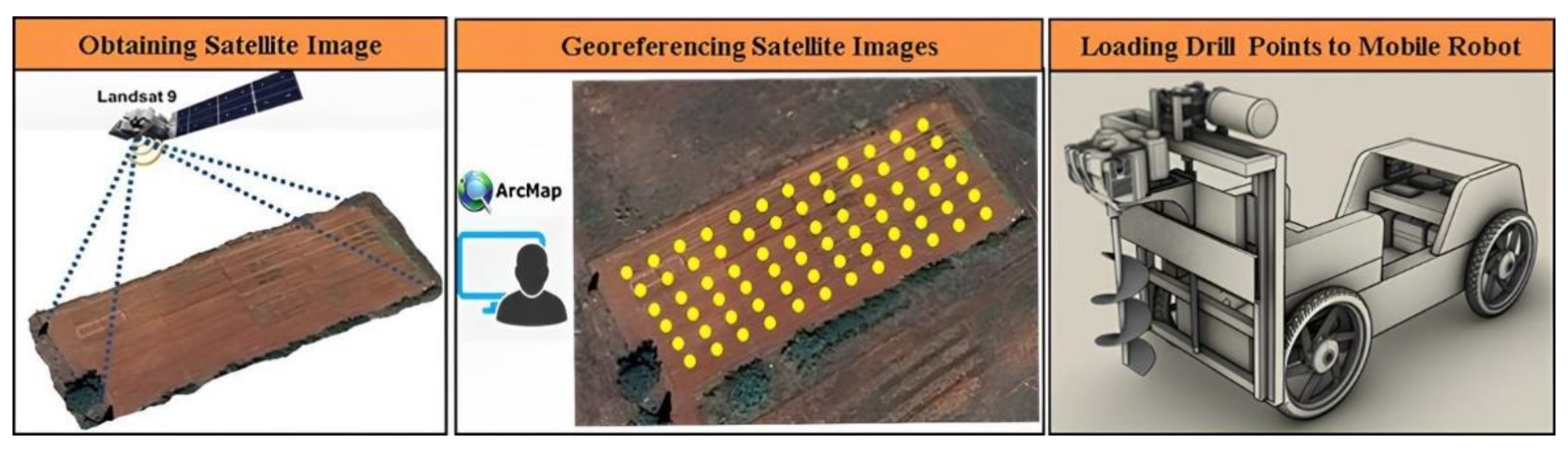
Figure 2.
Equipment used on GIS Based Autonomous Soil Drilling Robot and photo of the developed robot.
Figure 2.
Equipment used on GIS Based Autonomous Soil Drilling Robot and photo of the developed robot.
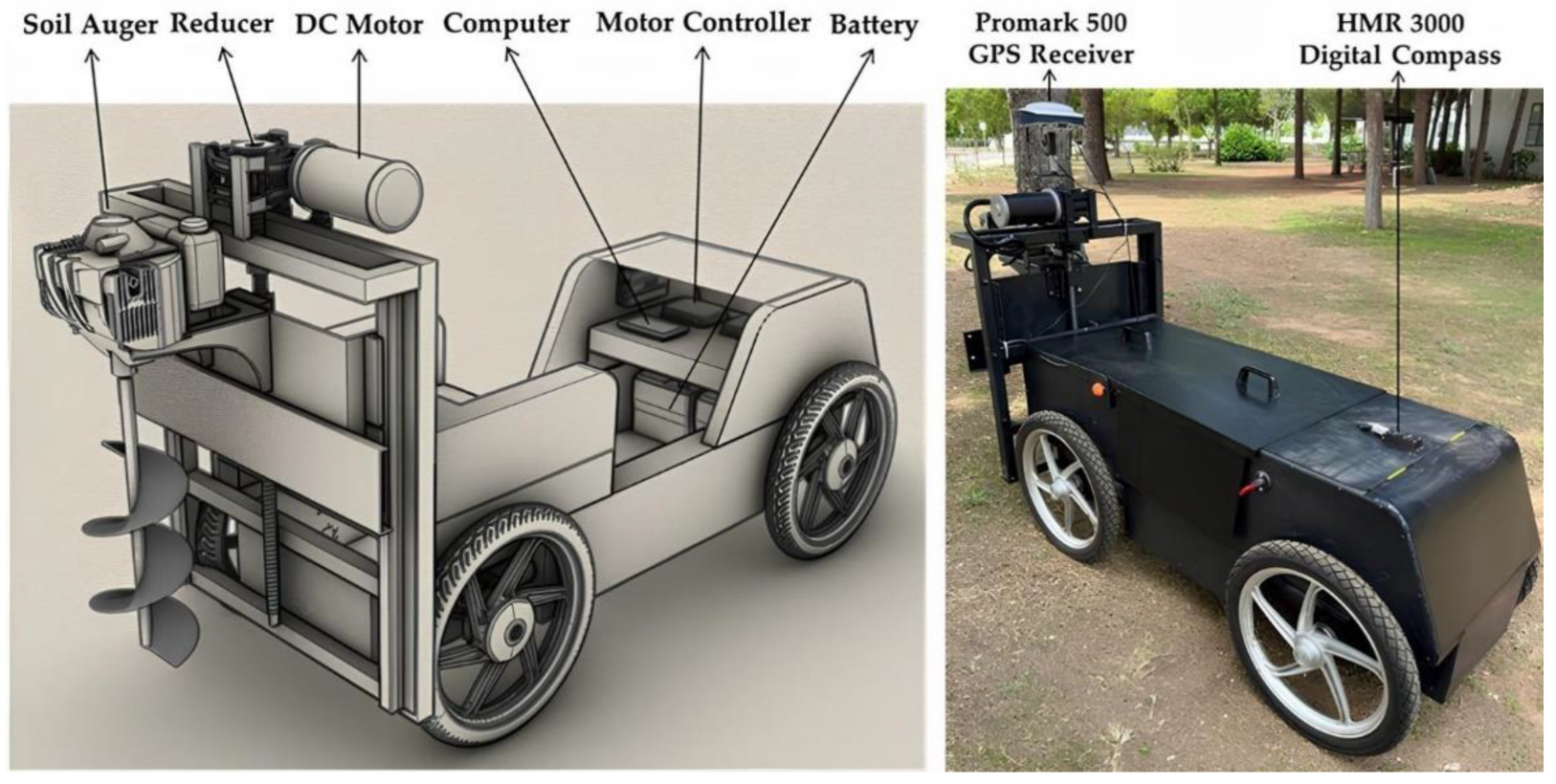
Figure 3.
Top, front, and side views of the technical drawing of the mobile robot.
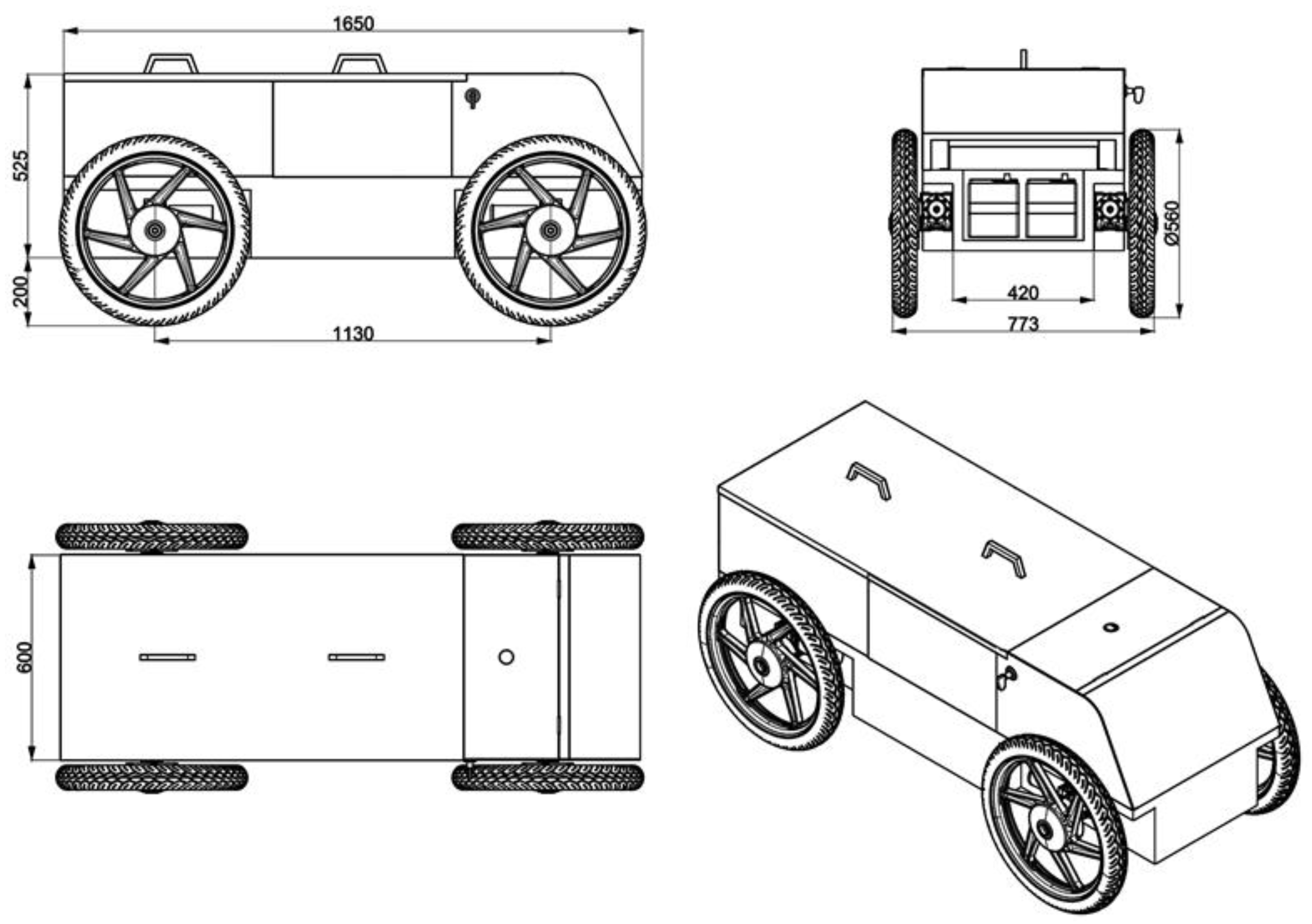
Figure 6.
Top, front, and side views of the technical drawings for the mobile robot attached to the soil auger machine.
Figure 6.
Top, front, and side views of the technical drawings for the mobile robot attached to the soil auger machine.
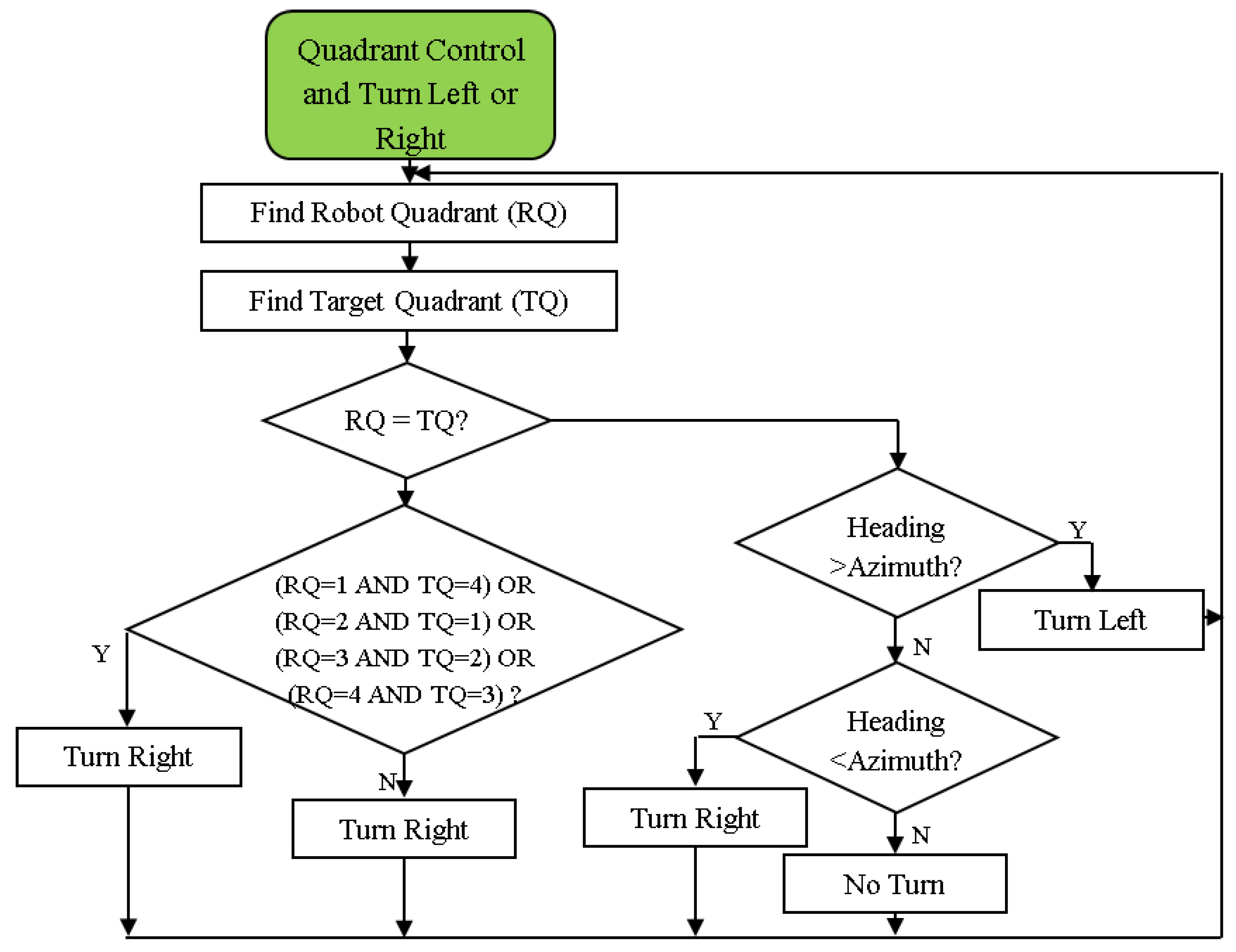
Figure 7.
Full-scale technical drawing of the soil auger machine and H-shaped grid.
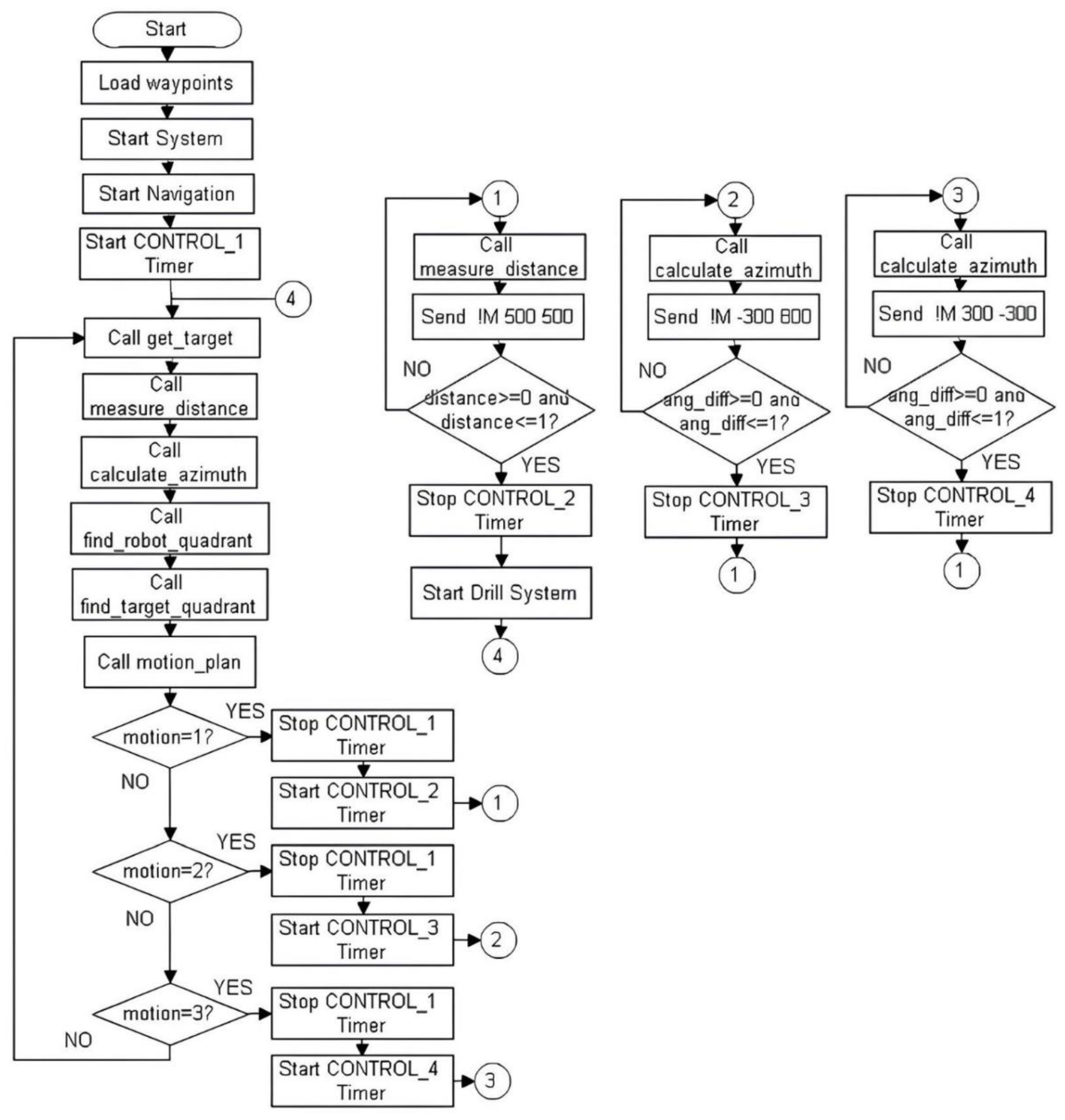
Figure 8.
The kinematics schematic of the differential drive mobile robot.
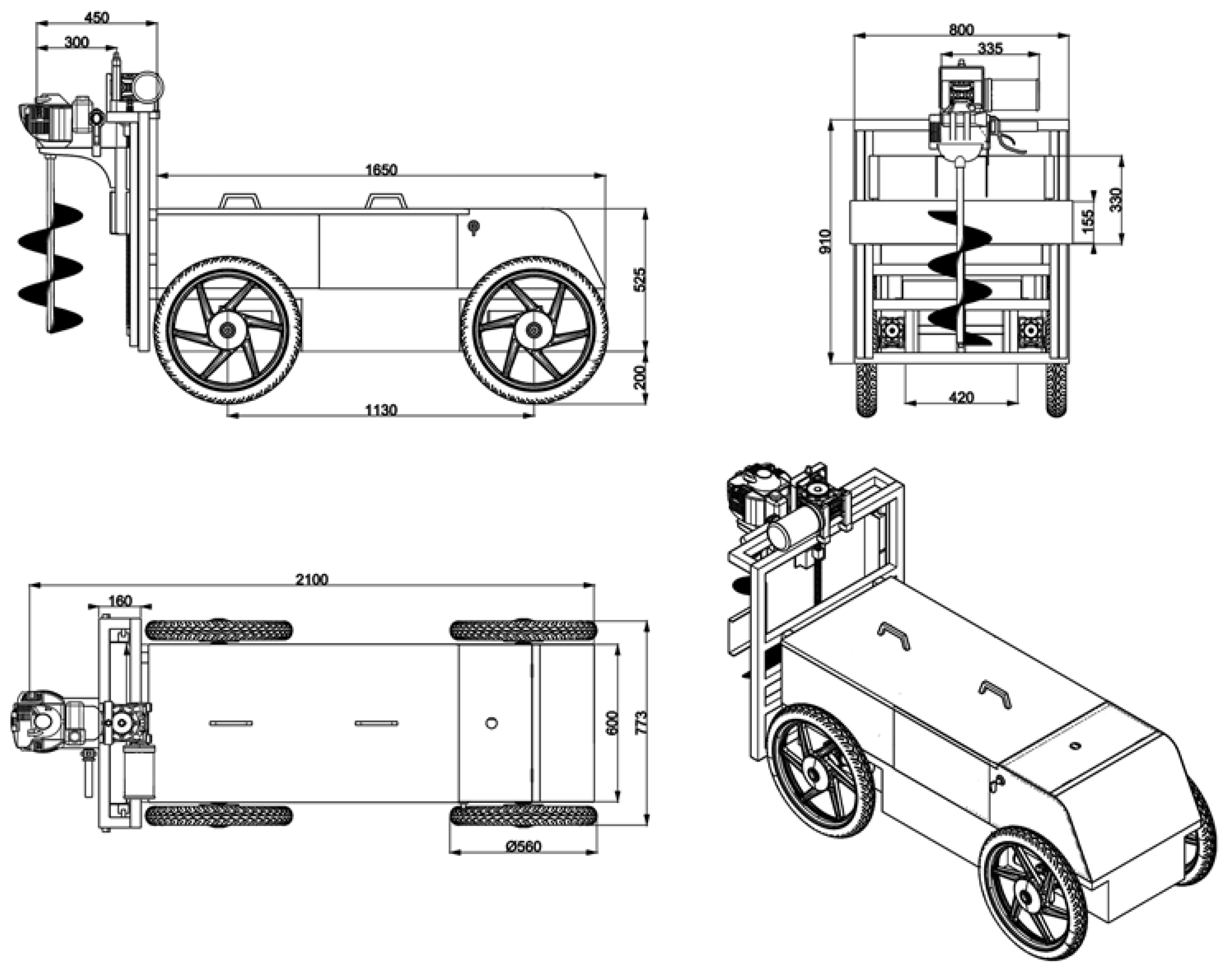
Figure 9.
ArcMap program in order to locate the seedling holes.
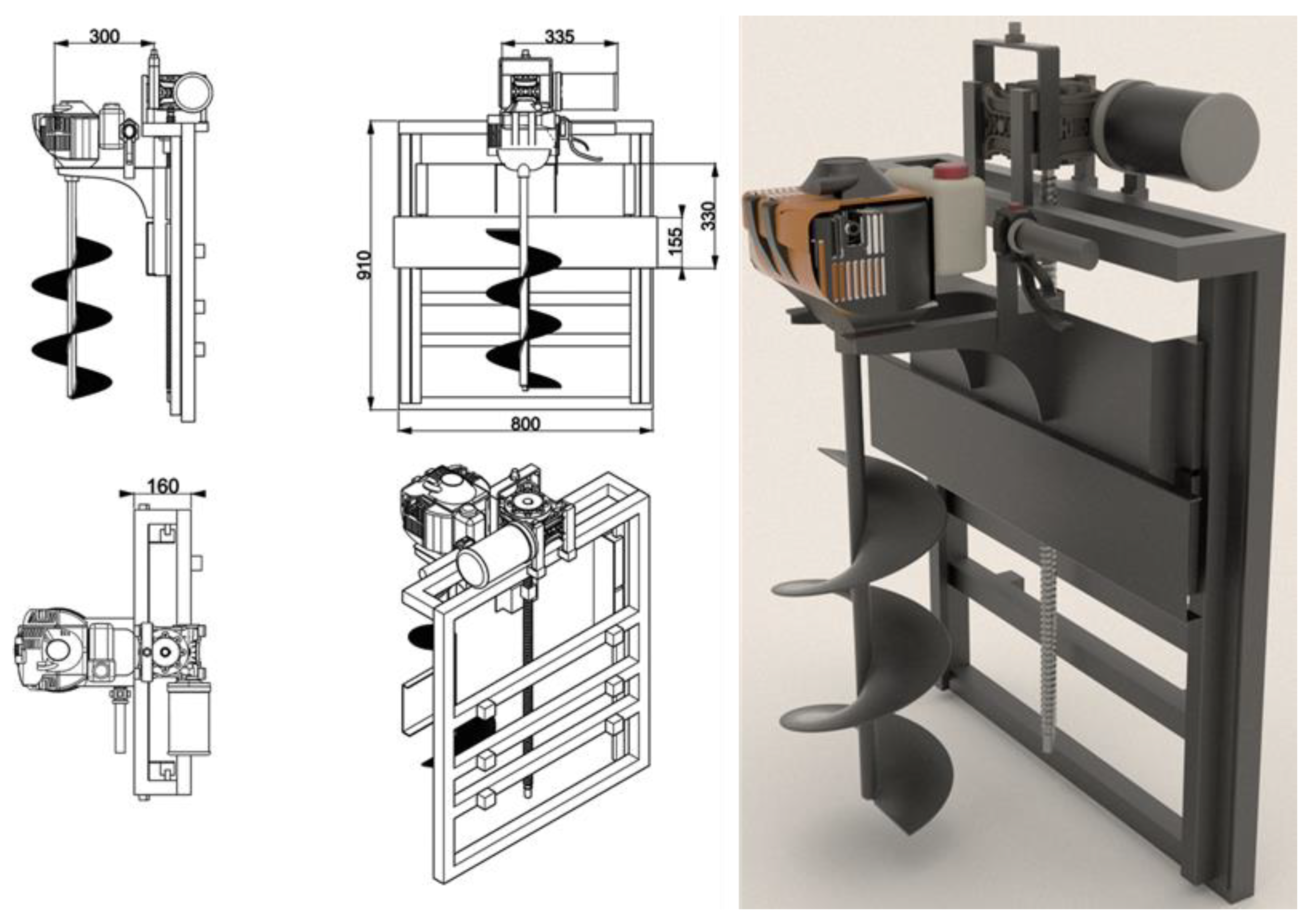
Figure 10.
Developed navigation and drilling software: (a) The software that was designed for mobile robot navigation; (b) soil drilling procedures.
Figure 10.
Developed navigation and drilling software: (a) The software that was designed for mobile robot navigation; (b) soil drilling procedures.
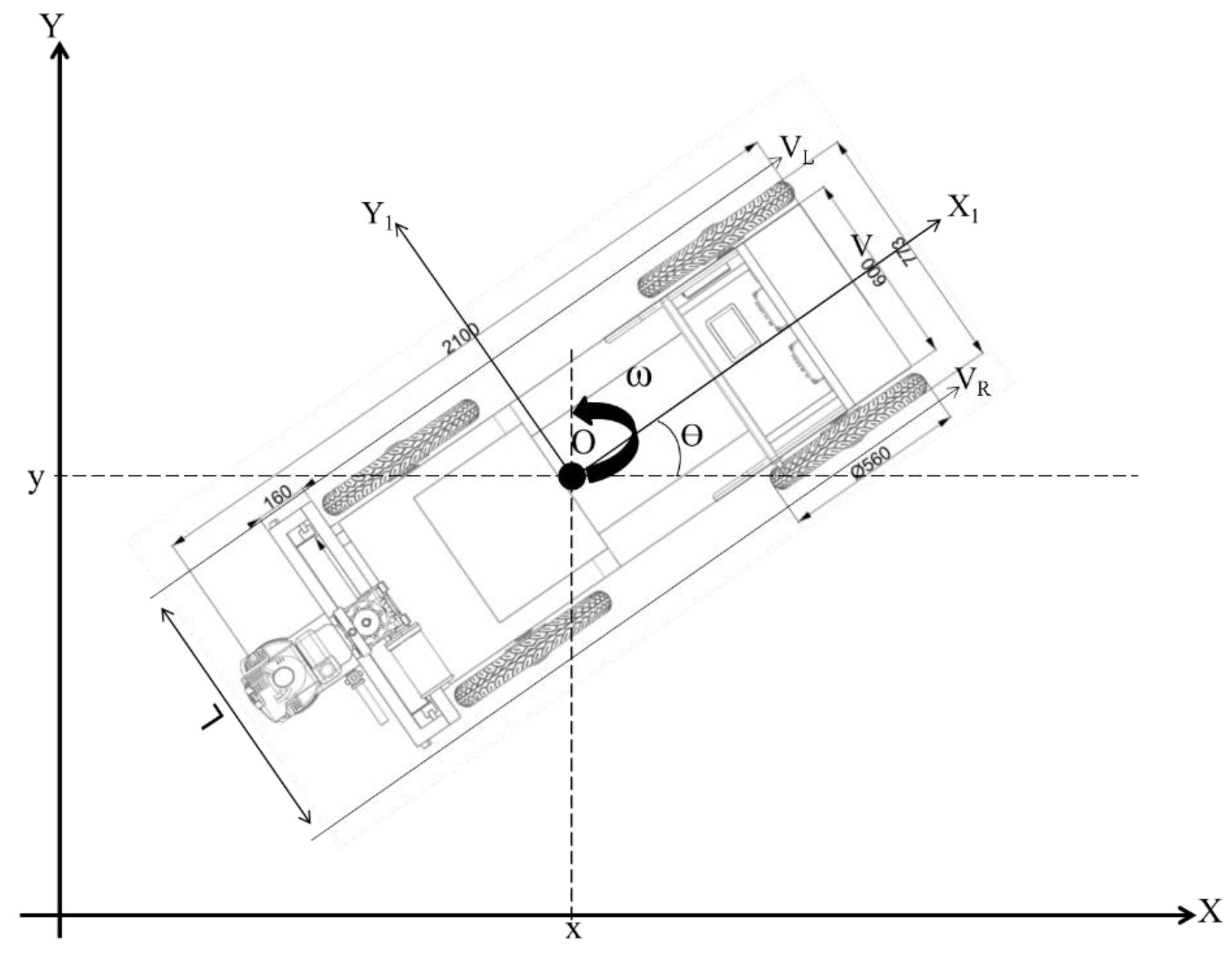
Figure 4.
The quadrant control mechanism’s flowchart [26].
Figure 4.
The quadrant control mechanism’s flowchart [26].
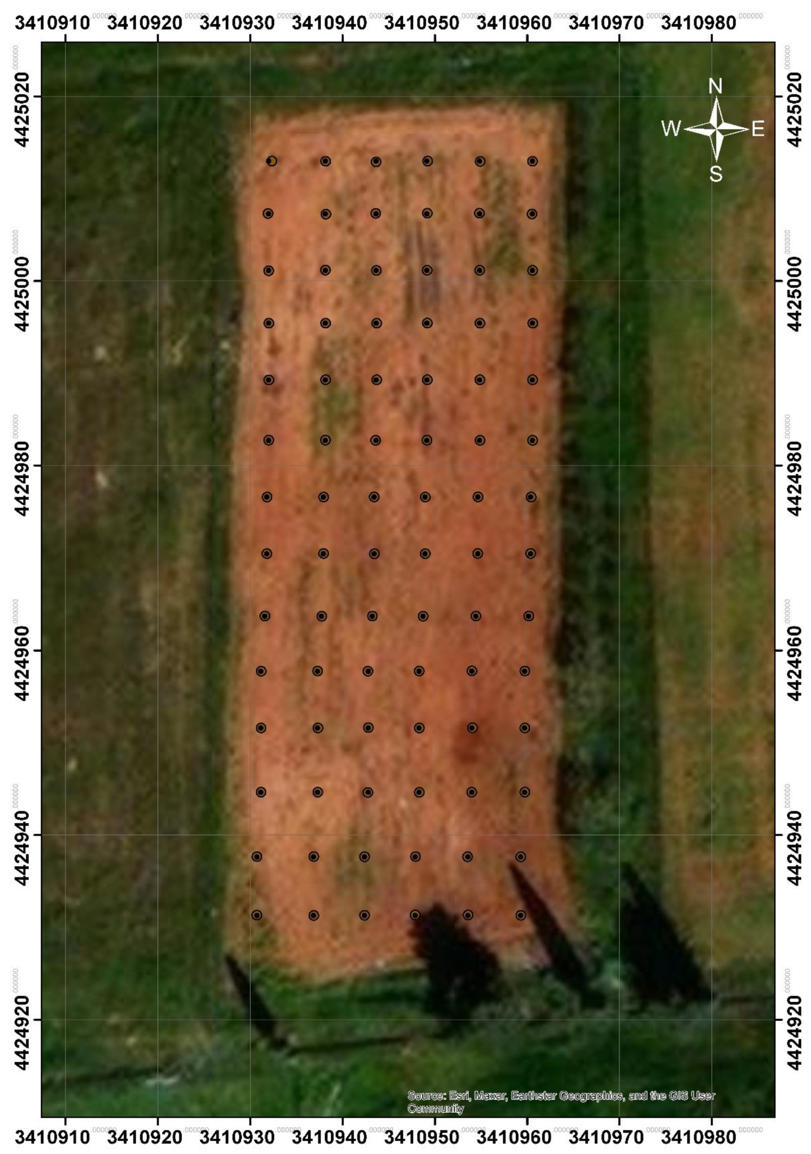
Figure 5.
The flowchart for the mobile robot navigation method.
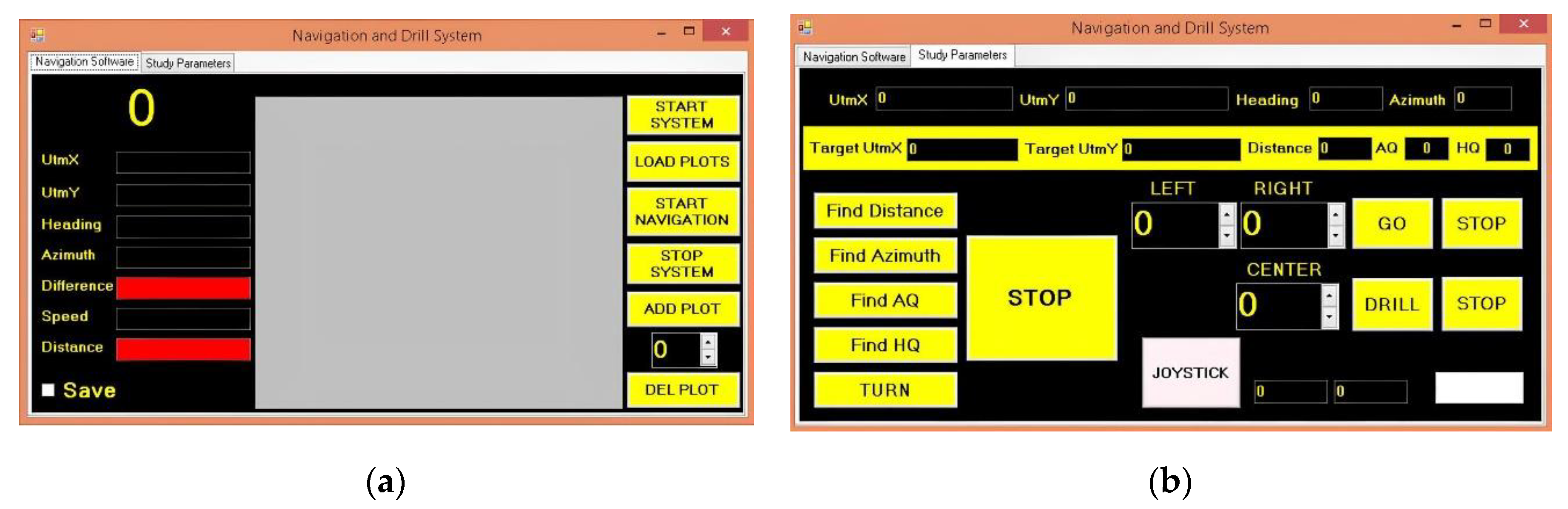
Figure 11.
The target locations and the locations where the mobile robot drills a hole.
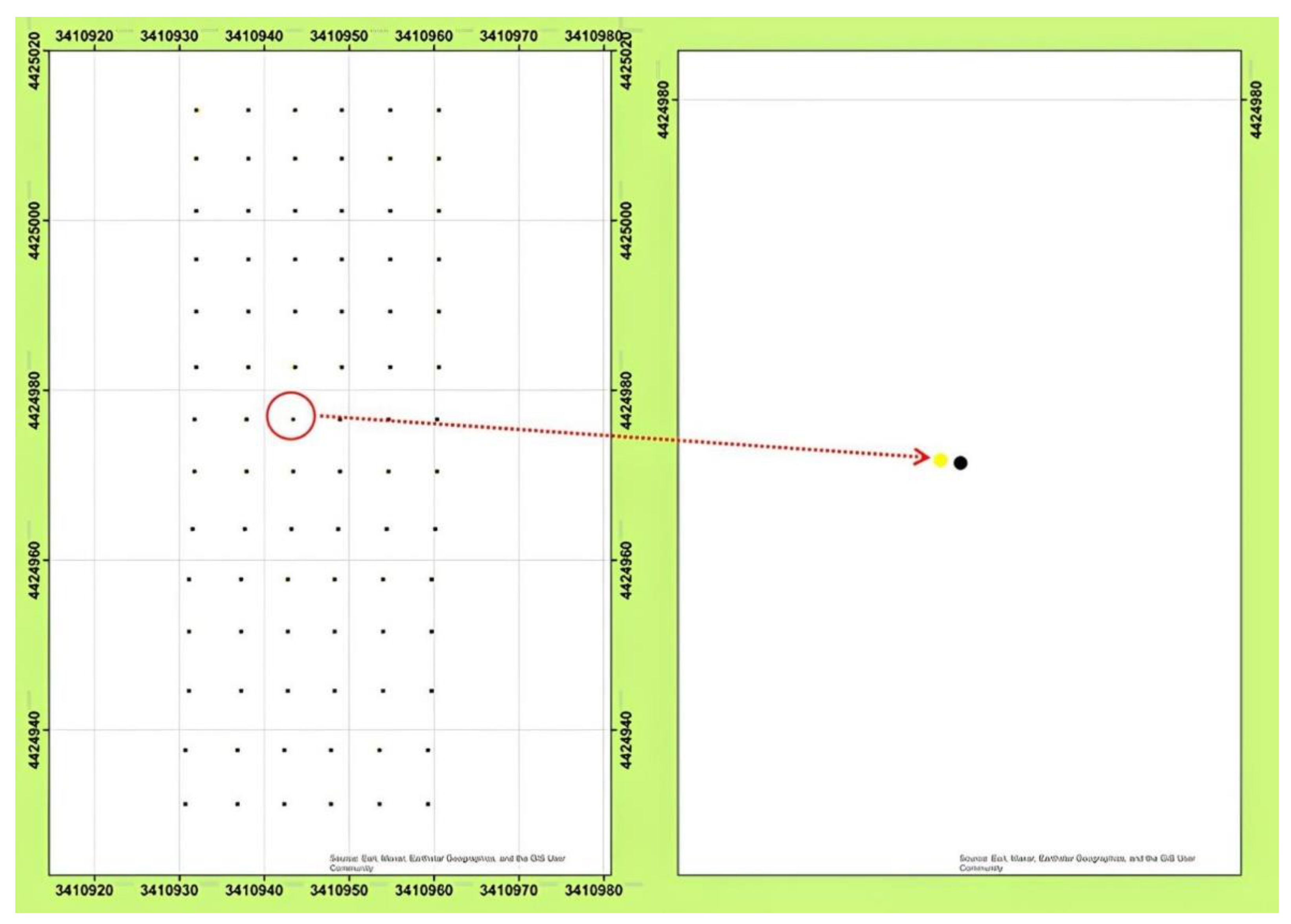
Figure 12.
The mobile robot’s images in the study field for drilling holes operation.
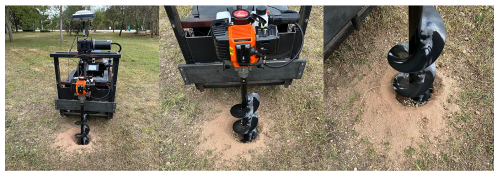
Figure 13.
The images of the drilled holes.
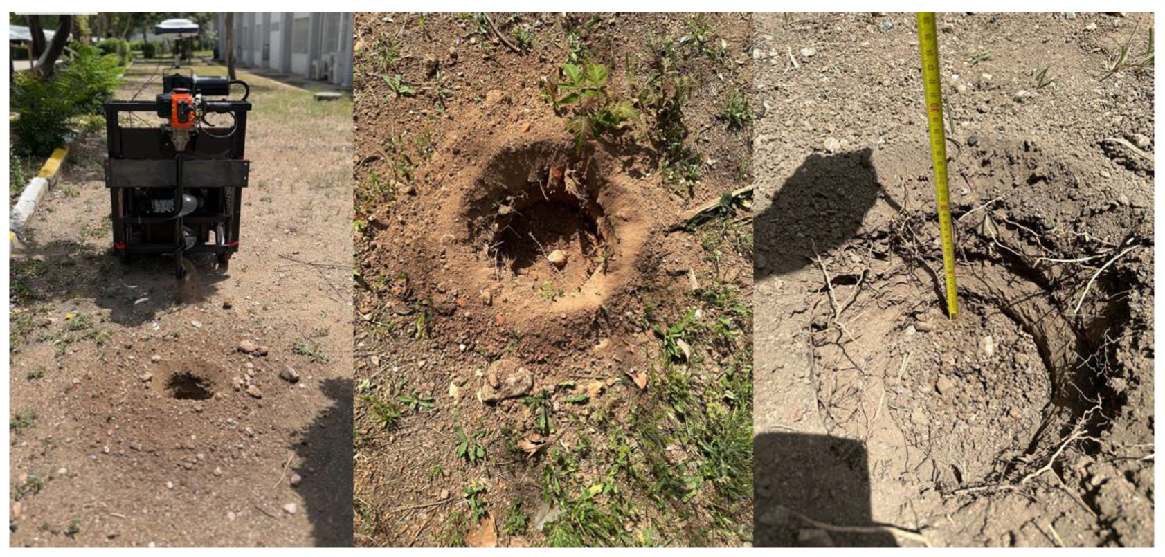
Figure 14.
Histogram of the XTE values of the mobile robot. The x-axis of a histogram represents the range of XTE values of the mobile robot. The y-axis represents the frequency or count of XTE values.
Figure 14.
Histogram of the XTE values of the mobile robot. The x-axis of a histogram represents the range of XTE values of the mobile robot. The y-axis represents the frequency or count of XTE values.
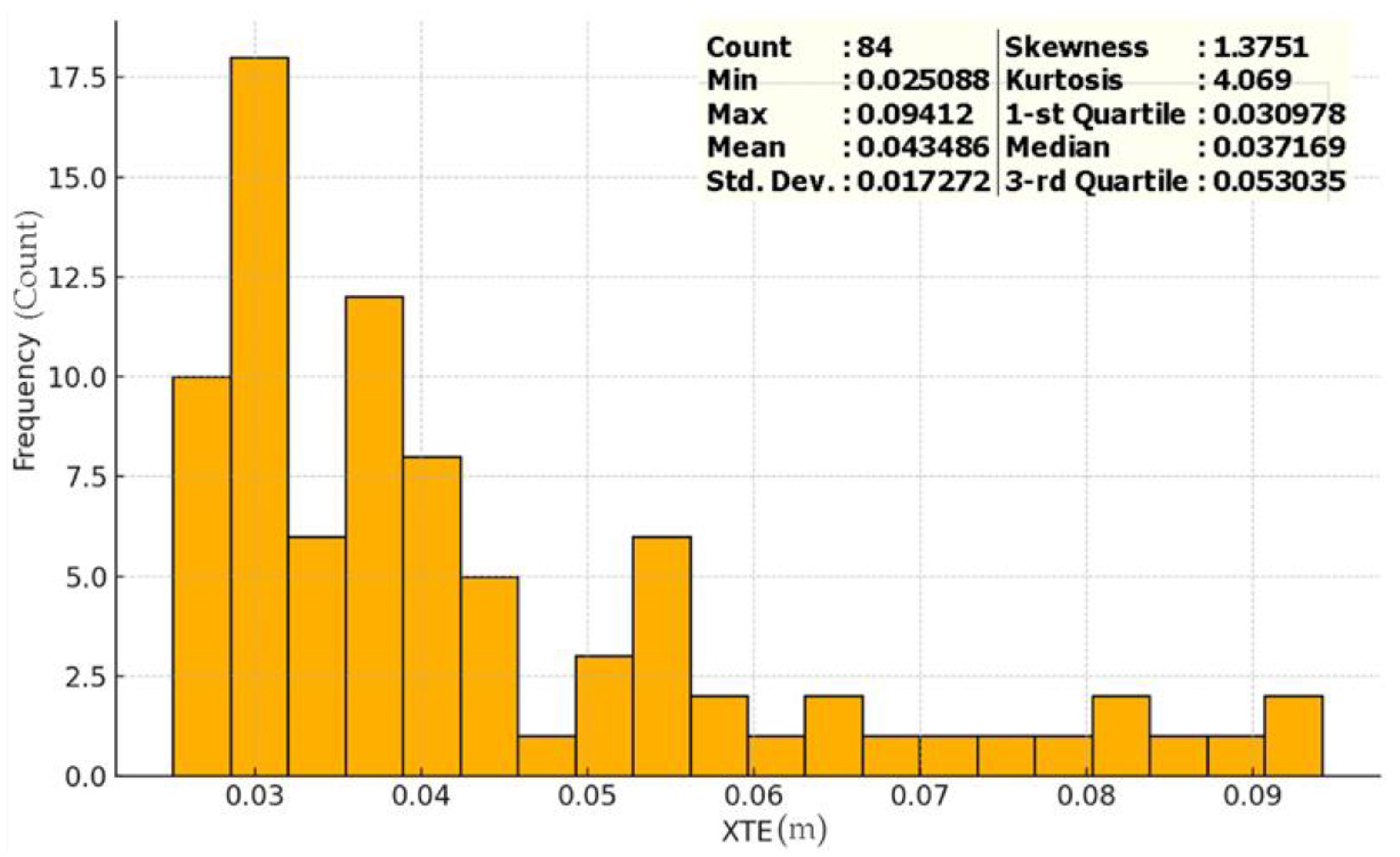
Figure 15.
Normal QQ plot of XTE values. This Q–Q plot compares the XTE values on the vertical axis to a statistical population on the horizontal axis.
Figure 15.
Normal QQ plot of XTE values. This Q–Q plot compares the XTE values on the vertical axis to a statistical population on the horizontal axis.
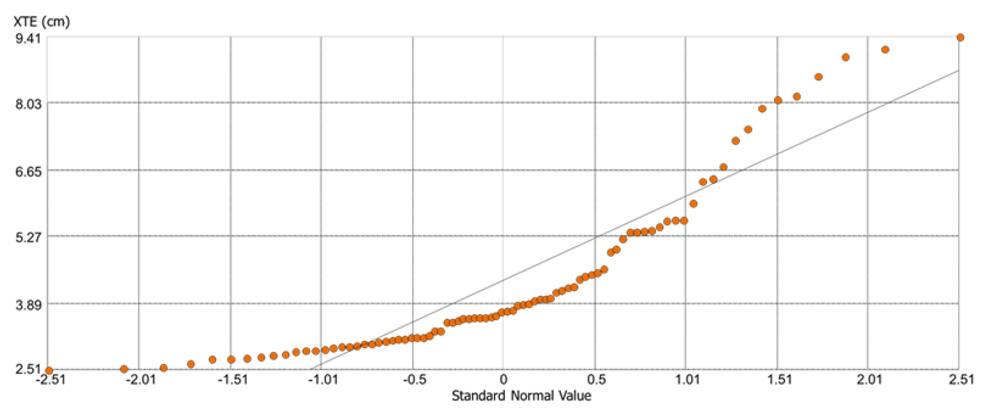
Figure 16.
The spatial distribution of the XTE. This spatial distribution map represents the correlation between XTE values and the all locations of the study field.
Figure 16.
The spatial distribution of the XTE. This spatial distribution map represents the correlation between XTE values and the all locations of the study field.


Table 1.
Mobile robot energy consumption and operating time calculation.
| Component | Current Draw (A) | Duration (s) | Total Current Seconds (A·s) |
| 250 W Motors | 3 | 7 | 21 |
| 500 W Motor | 15 | 40 | 600 |
| Other Components | 7.185 | 47 | 337.695 |
| Total | 958.695 |
Table 2.
Density of planting depends on the type of culture.
| Tree Name | Spacing between rows (m) | Spacing in rows (m) |
|---|---|---|
| Apple | 2.5 – 6 | 0.8 – 5 |
| Pear | 3.5 – 5 | 1.5 – 4.5 |
| Plum | 5 - 6 | 3.5 – 4.5 |
| Apricot | 5 – 6 | 3.5 – 5.5 |
| Peach | 4.5 – 5.5 | 3 – 4 |
| Cherry | 5 – 7 | 4 – 5.5 |
| Sour Cherry | 4 – 6 | 2 – 4.5 |
| Currant | 2.8 – 3 | 1 – 1.2 |
| Raspberry | 2.5 | 0.5 |
| Blackberry | 2.5 | 1.5 – 1.8 |
| Nut | 4 - 5 | 3 – 3.5 |
Disclaimer/Publisher’s Note: The statements, opinions and data contained in all publications are solely those of the individual author(s) and contributor(s) and not of MDPI and/or the editor(s). MDPI and/or the editor(s) disclaim responsibility for any injury to people or property resulting from any ideas, methods, instructions or products referred to in the content. |
© 2024 by the authors. Licensee MDPI, Basel, Switzerland. This article is an open access article distributed under the terms and conditions of the Creative Commons Attribution (CC BY) license (http://creativecommons.org/licenses/by/4.0/).
Copyright: This open access article is published under a Creative Commons CC BY 4.0 license, which permit the free download, distribution, and reuse, provided that the author and preprint are cited in any reuse.


