1. Introduction
Current mainstream technology for the fabrication of nanofiber membrane is electrospinning and it is enabling continuous and nanoscale fibers to be produced from different types of polymers, which have already shown immense potential across the fields in environmental protection, biomedicine, microelectronics and so on [
1,
2,
3].
Currently, single-nozzle electrospinning technology is the most widely used method to produce the nanofibers, which has relatively simple equipment and operation but the low productivity is still a huge problem to solve [
4,
5]. For improving the productivity in industrial-scale and high-quality production of nanofiber membranes, multi-needle and needleless electrospinning have emerged as techniques for efficient nanofiber fabrication which will be widely used in the future [
6,
7]. Needleless electrospinning systems commonly utilize a large rotating or stationary spinneret to ensure a sufficiently strong electric field to generate the individual or multiple polymer jets in the polymer solution surface, which can effectively avoid the clogging in the needle and attain the stable fabrication [
8,
9]. Although the above technology has the advantage of low-cost production, compared with the multi-needle electrospinning, there are still the following disadvantages that affect the performance and application of nanofibers. The first disadvantage is lower productivity, special nozzles (such as rotating disks, rollers, etc.) and high-precision control requirements result in higher maintenance costs. The second disadvantage is that needleless electrospinning lacks the concentrated charge in the needle tip, resulting in uneven distribution of the electric field in which influence the uniformity of fiber diameter and film formation [
10]. Compared to needleless one, multi-needle electrospinning demonstrates greater advantages in material adaptability and the diversity of film application [
11,
12,
13]. As the number of needles increases, productivity is greatly improved and the nanofiber diameter become easier to control, which is meeting requirements for large-scale nanofiber fabrication. The devices of Multi-needle electrospinning devices is mainly including high-voltage power supply, solution supply, multi-needle spinning module and collector [
14]. Combining individual needles as an integrated spinneret can effectively increase nanofiber yield. Applied voltage [
15], flow rate [
16] and needle length-to-diameter ratio [
17] are three critical parameters for designing multi-needle electrospinning devices. It has validated that the applied voltage and flow rate both can effect the multi-needle electrospinning process in existing research. In 2005, Angammana et al. [
18] designed a two to four needles electrospinning device and confirmed that stronger electric field interference exists in multi-needle systems could increase the deflection angle from the both sides of the needle tips and decline nanofiber uniformity. In 2008, Zhou et al. [
19] claimed the interference strength is closely related to the pitch between adjacent needle tips, and smaller pitch could lead to stronger interference and poorer fiber quality. However, most research are focusing on needle configurations currently, and there are only a few studies on flow rate control, which is determining the efficiency and productivity in electrospinning process [
20,
21].
In multi-needle electrospinning, it is difficult to ensure the same liquid flow are delivered to each needle tip. As the number of needles increases, achieving precise liquid flow control to the tip becomes a technical challenge [
22,
23]. It is not advisable to simply control and distribute the flow rate through a simple spinneret. It results in inconsistent flow rates across each needle, subsequently leading to poor electric field distribution, and resulting in non-uniform nanofiber. In multi-needle electrospinning spinneret, the layout and grading of flow runner can produce complicated effects. In the case of solution delivery to a multi-needle spinneret, it is of great significance to optimize the distribution of flow runners in which can ensure synchronized flow rates to reduce the problems caused by the jet at different flow rates, such as electrostatic interference, jet dripping and insufficient stretching [
24]. In 2006, Kim et al. [
25] investigated the relationship between nozzle geometry and fluid flow and utilized computational fluid dynamics to optimize nozzle structures. The simulation results showed that employing a hierarchical design with bend headers can keep each needle in synchronization flow. Wang et al. [
26] proposed a multi-needle electrospinning device to realize large-scale production of thermoplastic polyurethane (TPU) nanofiber. The spinneret was cylindrical with multiple linearly arranged needles, which can boost the yield of nanofiber but it is difficult to ensure consistent fluid flow to each needle. Gan et al. [
27] have proved that the distribution of the velocity and pressure is closely related to the structure of spinneret runners by using Fluent to make the simulation in the spinneret runners. Marla et al. [
28] have pointed out that the melt-blown outlet flow rate is relatively uniform during the production of nanofibers by using the hanger-type runners. But they have not applied the hanger-type structure runner to multi-needle electrospinning yet. In summary, it is very important for the widening nanofiber fabrication to develop a smooth spinneret to ensure the diameter uniformity of nanofiber.
Combining the hanger-type die heads runners [
29] and the research of spinneret runners [
30], the paper has proposed a novel multi-stage runner spinneret, which satisfies requirements for uniform distribution and velocity consistency of the flow. First, it is utilizing simulation to analyzing outlet velocity distributions across runner. After that, optimizing spinneret runner geometry and ensuring the pressure or flow rate delivery to each needle tip smoothly. And then, the effect between process parameter effects and nanofiber diameter is explored by constructing a regression model with response surface methodology (RSM) method. Finally, finishing the post-experiment data analysis via Design-Expert software and figure out the best statistical process parameters configuration.
2. Design and Simulation of Spinneret
The stability of the polymer outflow in the spinneret and the uniformity of the flow distribution are the keys to determining the quality of the nanofiber membrane. To ensure the performance of multi-needle electrospinning, the new multi-stage flow runner spinneret was designed. Finite element analysis was used to simulate the velocity during the polymer flow under different flow runner angles, and then the influence of flow runner with different structures on the stability of polymer flow was analyzed, which is providing guidance for the optimization of spinneret.
The geometric model and mesh division of the designed spinneret as shown in Figure 1 a-b respectively. The runners directly determine the polymer flow whether can be flowed out evenly so it is very important to consider the internal runner structure of spinneret. The structure of the multi-stage runners is roughly a clothes hanger type, as shown in Figure 1a, which can avoid the phenomenon of superfast flow and uneven distribution of polymer in the vertical flow runners. The polymer is squeezed into the flow runner inlet by applying high pressure. The polymer after entering the entrance is divided into two parts through the primary flow runner, and then two parts divided into four parts through the secondary flow channel, and divided into four parts through the thirdly flow channel, and finally reaches each outlet of the spinneret. Above structure facilitates the uniform polymer flow from entrance to each outlet. The design of the new spinneret is simplified to 8 outlets for simulation. The width is designed to be 800mm, the height is 240mm. The inlet size of the flow runner is 40mm×80mm and the inlet size of the secondary and thirdly flow runners are 25mm×15mm. The inlet size of the runners is 20mm×20mm and the height of the polymer retention area is 15mm. After the geometric model is established, the meshing is the key to simulation. Considering the requirements of meshing, some simplifications were made to the geometry of the flow runners, and small excessive fillets were ignored to improve calculation precision and speed. COMSOL is used to simulate the isothermal polymer flow process during electrospinning. The characteristics of polymer flow are mainly high viscosity and low Reynolds number. In order to meet the engineering conditions and simplify the calculation, the following necessary assumptions are made for the polymer flow. Steady-state flow occurs in the flow runners, the wall velocity is sat to zero, and only considering the viscous force.
The results of finite element analysis can guide the geometry and evaluation of different structural runner configurations for the novel spinneret. The two-dimensional or three-dimensional flow field velocity distribution can easily attain. Figure 2a-f shows the flow velocity distribution of polymer at different runner angles. It established six kinds of different spinneret flow runner structure for studying the influence of different angles on the velocity field and calculate the velocity distribution at the outlet. The difference between above structure is the angle between the primary flow runner are 130°, 140°, 150°, 160°, 170°, and 180° respectively. Gear pump is selected to continuously supply and the inlet pressure is 0.5Mpa. The research results have guiding significance for the optimization of new spinnerets.
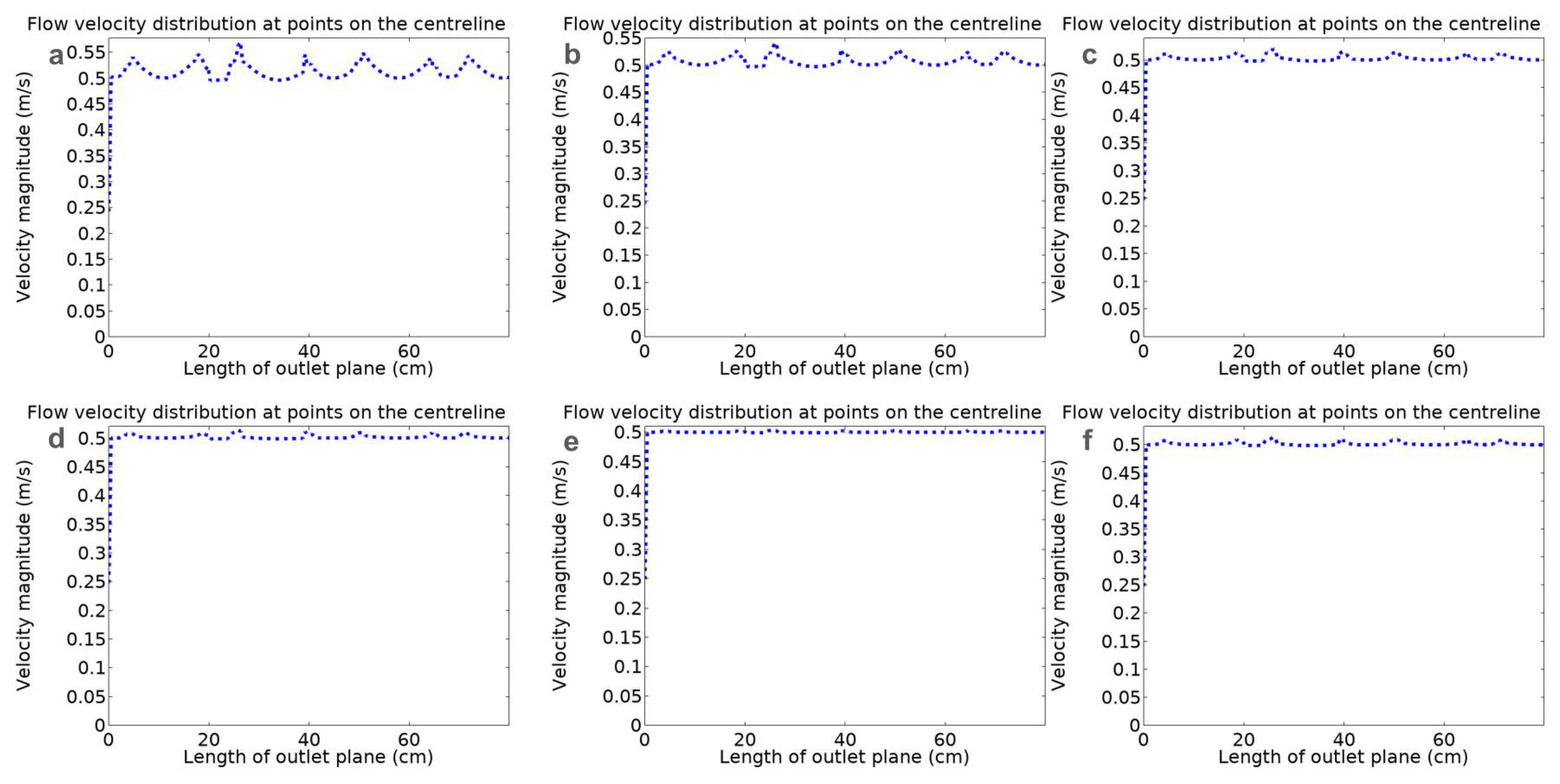
According to the flow distribution of the polymer at different angles in the spinneret runner, the flow velocity distribution curve at the outlet can be obtained, as shown in
Figure 3a-f. The abscissa is the length of the outlet and the ordinate is the flow velocity at different part at the outlet. It can see that each curve represents the velocity at the outlet and the velocity distribution at each point on the outlet are draw. In order to compare the flow rate at same outlet with different angles, 100 points are taken evenly in the width direction and the flow rate of the polymer vertical to the outlet plane are extracted for analysis. Setting U as the maximum deviation between the real flow velocity of each point and the average flow velocity, which is an indicator to evaluate the non-uniformity degree of flow velocity. The
(i=1,2,3,4...,100) represents the polymer velocity at each point in the direction vertical to the outlet plane.
Since different flow runner meet and merge in the polymer retention area, more fluid will flow longitudinally, i.e. vertical to the direction of the outlet plane, which results in the formation of an uneven velocity area. The increase in the angle will slow down the polymer flow rate, so making the outlet velocity more uniform. After passing through primary flow runner, the velocity gradually slows down. Before entering the secondary flow runner, the polymer flow generate fluctuation. It is because the size of the secondary flow had changed, which caused readjustment of the fluid flow. Finally, after the thirdly flow runner, the velocity in the spinneret is decreased. Each flow runners shrinks according to a proportion until it connects in the flow retention area, which all plays the role of distribution and buffering. The primary runner affects the polymer distribution and determines the polymer supply situation of the subsequent runners. It can be seen from the figure.4 that as the angle increases, the flow velocity at the outlet centerline becomes more and more uniform. This trend can be seen from the calculation results of the non-uniformity index U. When the angle is 130°, U is 9.1%. When the angle increases to 140°, the U is 8.36%. When the angle is 150°, the U is 7.81%. When the angle is 160°, the U is 5.67%. When the angle is 170°, the U is 4% and when the angle is 180°, the U is 6.38%. Through simulation, it was found that as the angle increases, the uniformity of the overall outlet flow rate can be further improved. However, when the angle is 180°, the polymer flow velocity will slow down in the area, which also affects the uniformity of flow distribution. It is easy to produce vortex and flow buffering effects in the end of primary runner, affecting the uniformity of flow distribution.
3. Experiment
3.1. Experimental Materials
Polyvinylidene fluoride (PVDF) with an average molecular weight of 300,000 g/mol (USA, Sigma-Aldrich) and N, N-dimethylformamide called DMF (China, Shanghai Aladdin Chemical Co) are used as received without further purification.
3.2. Characterization
In order to observe the fiber morphology more clearly, following instruments were used to assist in characterization. The plasma thin film sputtering instrument (IBS, ISC150, SuPro) is used to spray gold on the fiber membrane. Then, the scanning electron microscope (SEM, TM3030, Hitachi) is used to observe the morphology of the nanofibers. Next, the nanofiber diameter was measured using Image J software (NIH, USA) in which is selecting approximately 100 nanofibers in each sample to measure the diameter. Finally, Origin software was used to draw the distribution frequency of fiber diameter.
3.3. Experimental Design
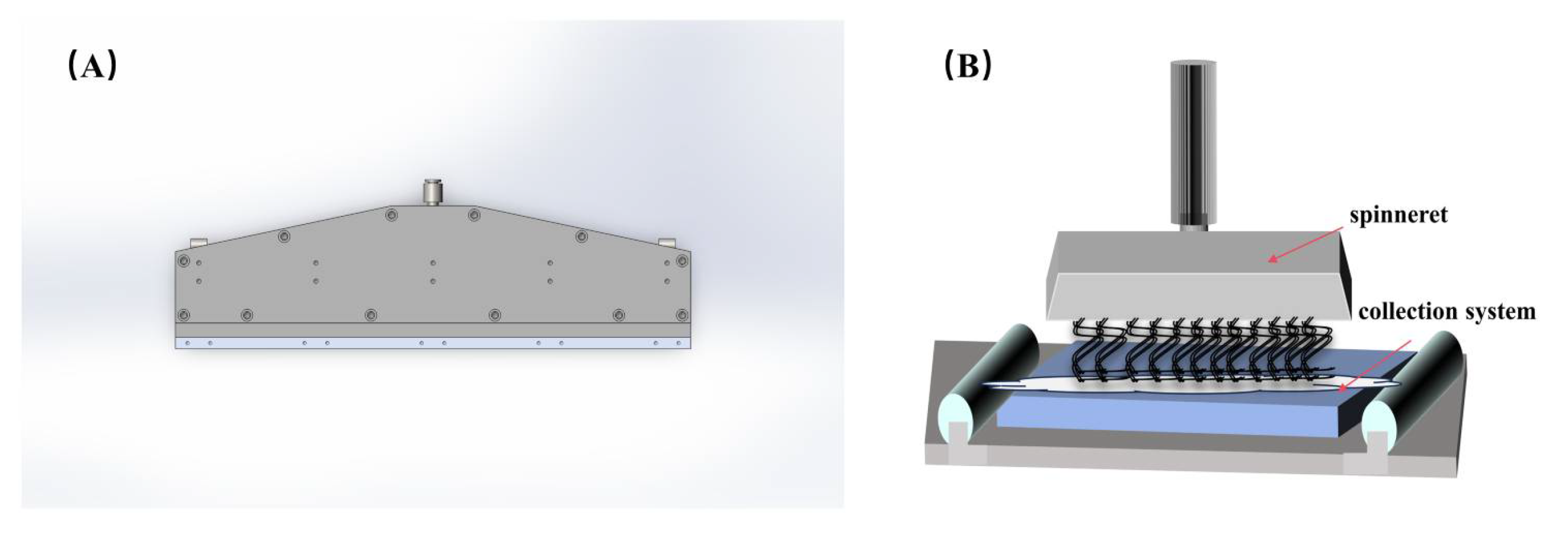
A novel multi-stage runners spinneret was used to fabricate the nanofiber membranes in this experiment, as shown in
Figure 4a. First, the prepared polymer solutions are transported to the liquid supply module. And then, adjusting the distance between the collector and the needles to make sure the distance is suitable. Next, the high spinning voltage is applied in the spinneret by high-voltage power module. Under the influence of the electric field force, the jet is pulled to the grounded collector, as shown in
Figure 4b. Finally, the nanofibers composed of micro-nano sized jets is obtained and gradually generate the membrane products.
In order to study the influence between process parameters and diameter on the generated nanofibers, the Box-Benhnken (BBD) response surface method was used to design experimental plans and analyzed the experimental results. The floating range of the process parameters was found based on single-factor experiments individually, which are needed to optimized and divided into three factor levels as shown in
Table 1. The coding levels of spinning voltage are 55kv, 60kv and 65kv, and the collection distance are 20cm, 25cm and 30cm, the solution concentrations are 11wt%, 13wt% and 15wt%. According to the BBD method, the 17 sets coding factor of process parameters are combined to design the optimal experiments. After that, it has achieved every nanofiber diameter data as shown in
Table 2.
4. Results and Discussion
4.1. RSM Testing
Establishing a regression model can optimize process parameters and predict response indicators, and finally obtain the optimal regression fitting equation. Using Design-Expert software, a response surface regression model and a response index mathematical model were constructed for the average fiber diameter data obtained from the experiment, as shown in
Table 4. Comparing and evaluating the P-value of above model with the significance level, the P-value is used to analyze the significance of the objected model. When P > 0.1 indicates that the response model is not significant. When P < 0.05, it means that the model is significant level. When P < 0.0001, it means that the response model has reached an extremely significant level. The analysis results show that C and C2 are important model factor and their P values are less than 0.0001, which is indicating that the effect of solution concentration is extremely significant. The P value of B less than 0.05, which is indicating that the collection distance has a significant effect on the nanofiber diameter. The P values of the remaining factors were all higher than 0.1, which is indicating that they had slight effect on the nanofiber diameter. Comparing the mean square values, it is found that the influence strength of process parameters on nanofiber diameter is C>B>A; the strength of interaction is AB>BC>AC. In this experiment, the response index mathematical model established using the RSM method is:
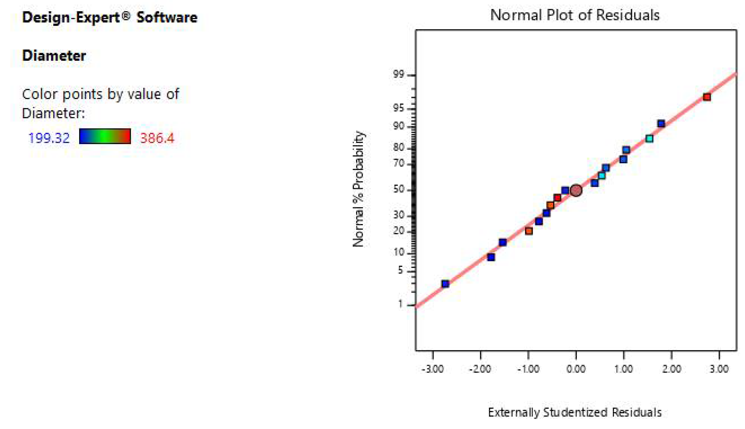
The residual normal probability plot is used to verify the model reliability by observing the data whether obeys a linear distribution basically. The normal probability plot is shown in
Figure 5. The data in the
Figure 5 basically shown as a beeline, which shows that the accuracy of the model is reliable.
4.2. Response Surface Analysis
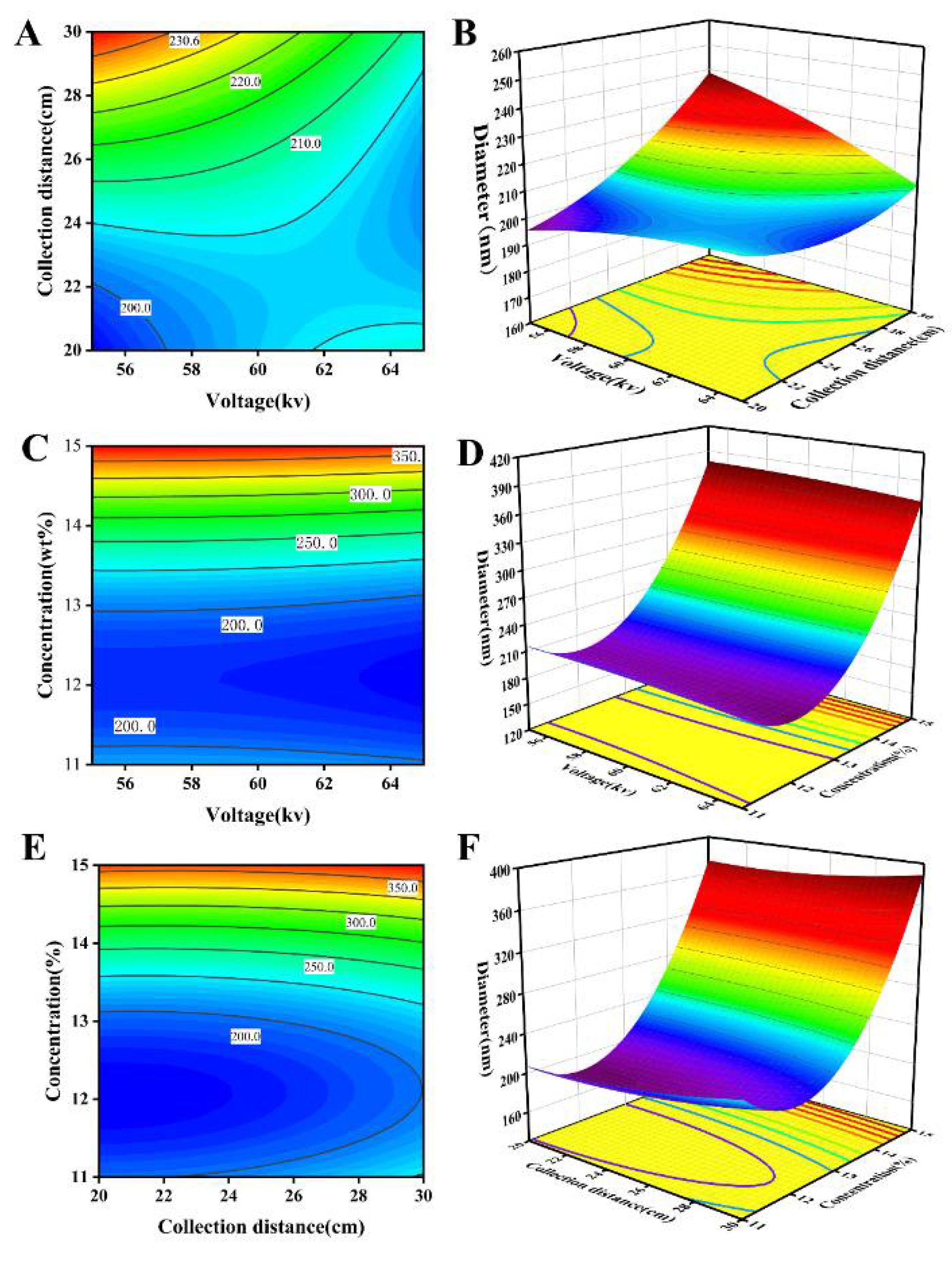
It studies the influence of different process parameters on the average diameter of nanofibers and then the response surface curve is draw through Design-Expert software, as shown in
Figure 6. Process parameter is voltage, collection distance, and solution concentration. It shows the 2D and 3D response surface profiles of the interaction between voltage and collection distance in
Figure 6a-b. As the spinning voltage increases, the average diameter of the nanofibers decreases relatively. Because as the voltage increases, the electric field intensity and the repulsive force of the fluid jet increase, it is conducive to fiber thinning and the average nanofibers diameter will directly decrease. However, higher spinning voltage will also aggravate the electric field interference, which is affecting the stable formation of Taylor cones and the jet flow trajectory. Above phenomenon is not conducive to fiber thinning, so it can be seen that the influence of higher voltage in nanofiber diameter is very weak. It shows the 2D and 3D response surface profiles of the interaction between voltage and solution concentration, as showed
Figure 6c-d. From the profiles, it can be described that the solution concentration has a significant effect on the average nanofiber diameter. When the concentration is low (about 11-12%), the increasing concentration will improve the viscosity and conducive to the generation of better fibers. When the concentration continues to increase (higher than 12%), the viscosity increases rapidly, and it becomes more difficult for the electric field force to exceed the surface tension of the jet, so the diameter will be larger. It shows the 2D and 3D response surface profiles of the interaction between collection distance and solution concentration in
Figure 6e-f. The value of average nanofiber diameter increases with the collection distance value increases. When the collection distance is farther, it will cause that the flight time of the jet is longer with more fully the solvent evaporates and the concentration improves. The high-concentration solutions have a lower probability to generate better diameter fibers. Additionally, long-distance flight time of the jet will also attenuate the electrostatic potential, which weaken the electric field force and ultimately affected the fiber diameter.
4.3. Optimization and Validation
The process parameter equation from RSM model was analyzed in the Design-Expert software, and the extreme points of the response indicators were automatically explored through the optimization, which can figure out the best process parameters configuration. The parameters are configured as 12% solution concentration, 25cm collection distance and 59kV spinning voltage. The average value of nanofibers diameter acted in the best parameters configuration is 199.92nm. Using this parameter configuration to conduct the repeated experiments for verifying the optimal results, and the average diameter of repeated experiments is 195.69nm. Compared with the optimal results 199.92nm, the deviation is only 2.11%. It indicates that the regression equation constructed through RSM is relatively accurate and can be used for process optimization of multi-needle electrospinning systems.
4.4. Microscopic Morphology
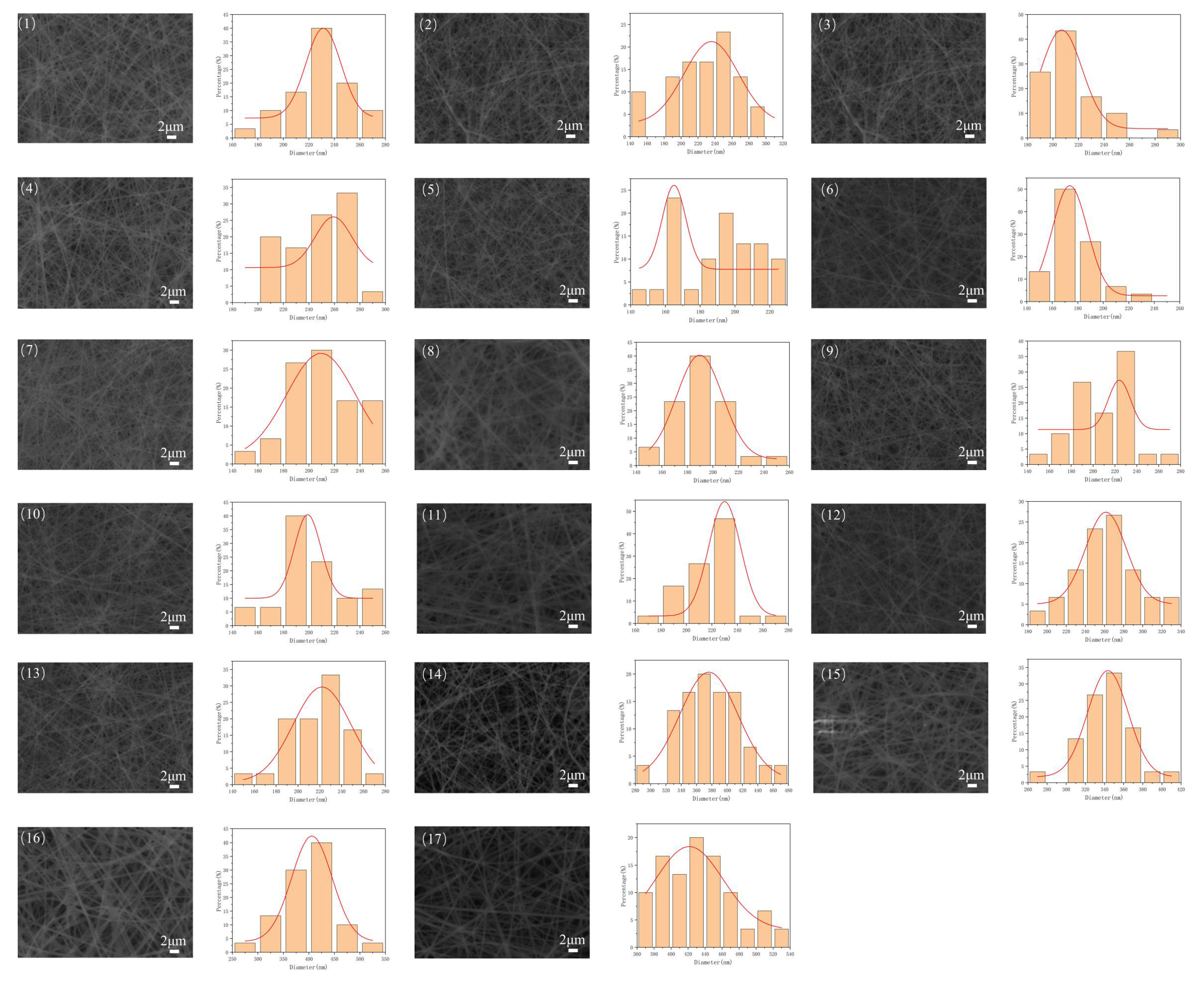
Scanning electron microscopy (SEM) is used to observe the microscopic morphological of the nanofiber membrane, ImageJ software is used to analyze the SEM images and Origin software is used for drawing the distribution of fiber diameters. The SEM images and diameter distribution are shown in
Figure 7. There are four groups with a concentration of 11wt% and its corresponding SEM images and fiber diameter distribution are
Figure 7(1)-(4). Due to the relatively low concentration (11wt%), bead-like nanofibers were formed. There are still have differences between the nanofibers diameter in above four experimental results and the average diameter of nanofibers is 204.21nm. By comparing the nanofiber diameters of
Figure 7(1) and (4), it can known that the nanofiber diameter increases as the collection distance increases under the same 11wt% concentration. By increasing the spinning voltage, it will increase the electric field intensity and the electric field force, which is causing the polymer solution be suffered greater tensile force during the spinning process and fabricated the thinner nanofibers, as shown in
Figure 7(10)-(11). As the voltage increases, thinner nanofibers can be obtained, while the difference in fiber diameter is reduced and the diameter is more uniform. There are nine groups experiments results conducting with 13wt% concentration as show in
Figure 7(5)-(13). Observing the SEM images relatively, the overall morphology of the fiber membrane is evenly distributed and the diameters are relatively thin. The diameter range of nanofibers is [196.17, 233.04] nm. There are four groups experiments results conducting with 15wt% concentration as show in
Figure 7 (14)-(17). The nanofibers average diameter of the above 4 groups were 338.91nm. Compared with the other experimental results of low-concentration, the nanofibers fabricated with high concentration are thicker.
5. Conclusions
In the paper, it designs a new multi-stage runner spinneret to achieve large-scale fabrication of nanofiber membranes. COMSOL Multiphysics 6.0 was used to simulate the velocity distribution of polymer solution at different runner angles inside the spinneret. When the angle of the primary flow channel is 170°, the non-uniformity U of the spinneret outlet is minimized. The BBD response surface method was used to conduct electrospinning experiments for data analysis, and a mathematical regression fitting model between process parameters and average diameter was established, the significance and error analysis of the model were performed. It was concluded that the solution concentration has the most significant effect on the diameter compared with voltage and collection distance. By analyzing the experimental results, it is known that when the solution concentration is 11 wt%, bead-shaped nanofibers can be generated. When the solution concentration is 13 wt%, the nanofibers are generally thinner and the standard deviation of the diameter is the smallest, which means the overall diameter distribution is uniform. When the solution concentration is 15 wt%, the average diameter is the largest, ranging from 296.19 to 436.64nm. Based on the results, the optimal electrospinning process parameter configuration was obtained, which the PVDF concentration is 12 wt%, collection distance is 25 cm and spinning voltage is 59 kv. It provides a convenient and effective approach for fabricating the nanofibers with high-uniform diameter.
Data Availability
The data that support the findings of this study are available from the corresponding author upon reasonable request.
Conflict of Interest: The authors declare that they have no competing interests. Ethical approval: Not applicable.
Author Contributions
J.J. and X.C. was involved in conceptualization, methodology, investigation, formal analysis, and writing original draft, Writing review and editing ; H.W. contributed to writing original draft, methodology, project administration; W.O. contributed to methodology, writing original draft, Writting review and editing; J.H. contributed to investigation, visualization, writing Original Draft; M.L. contributed to investigation, visualization; Z.L. contributed to investigation; J.H. contributed to visualization; G.Z. contributed to conceptualization; D.W. contributed to Funding acquisition.
Funding
This study was supported by the Basic and Applied Basic Research Foundation of Guangdong Province(Grant No. 2023A1515010945)and the open project of State Key Laboratory of Precision Electronic Manufacturing Technology and Equipment, Guangdong University of Technology (Grant No. JMDZ 2021019 and JMDZ 2021014)
Acknowledgements
Not applicable.
References
- Bhagure SS, Rao DrAR (2020) A Review: Electrospinning and Electrospinning Nanofibre Technology, Process & Application. Int J Innov Sci Res Technol 5:528–538. [CrossRef]
- Zhang X, Xie L, Wang X, et al (2022) Electrospinning super-assembly of ultrathin fibers from single- to multi-Taylor cone sites. Appl Mater Today 26:101272. [CrossRef]
- Li H, Xu M, Shi R, et al (2022) Advances in Electrostatic Spinning of Polymer Fibers Functionalized with Metal-Based Nanocrystals and Biomedical Applications. Molecules 27:5548. [CrossRef]
- Ge X, Hu N, Yan F, Wang Y (2023) Development and applications of electrospun nanofiber-based triboelectric nanogenerators. Nano Energy 112:108444. [CrossRef]
- Fakirov S (2016) Nano-size Polymers. Springer International Publishing, Cham.
- Partheniadis I, Nikolakakis I, Laidmäe I, Heinämäki J (2020) A Mini-Review: Needleless Electrospinning of Nanofibers for Pharmaceutical and Biomedical Applications. Processes 8:673. [CrossRef]
- SalehHudin HS, Mohamad EN, Mahadi WNL, Muhammad Afifi A (2018) Multiple-jet electrospinning methods for nanofiber processing: A review. Mater Manuf Process 33:479–498. [CrossRef]
- Ning P, Shi H, Niu P, et al (2019) Electric field analysis of auxiliary electrode in needle-free electrostatic spinning. Ferroelectrics 548:60–71. [CrossRef]
- Niu H, Wang X, Lin T (2012) Needleless electrospinning: influences of fibre generator geometry. J Text Inst 103:787–794. [CrossRef]
- Huang Y, Song J, Yang C, et al (2019) Scalable manufacturing and applications of nanofibers. Mater Today 28:98–113. [CrossRef]
- Yang Y, Jia Z, Li Q, et al (2010) A shield ring enhanced equilateral hexagon distributed multi-needle electrospinning spinneret. IEEE Trans Dielectr Electr Insul 17:1592–1601. [CrossRef]
- He J, Zhou Y (2019) Multineedle Electrospinning. In: Electrospinning: Nanofabrication and Applications. Elsevier, pp 201–218.
- Zhu Z, Wu P, Wang Z, et al (2019) Optimization of electric field uniformity of multi-needle electrospinning nozzle. AIP Adv 9:105104. [CrossRef]
- Lyons J, Li C, Ko F (2004) Melt-electrospinning part I: processing parameters and geometric properties. Polymer 45:7597–7603. [CrossRef]
- Beachley V, Wen X (2009) Effect of electrospinning parameters on the nanofiber diameter and length. Mater Sci Eng C 29:663–668. [CrossRef]
- Zargham S, Bazgir S, Tavakoli A, et al (2012) The Effect of Flow Rate on Morphology and Deposition Area of Electrospun Nylon 6 Nanofiber. J Eng Fibers Fabr 7:155892501200700. [CrossRef]
- Theron SA, Zussman E, Yarin AL (2004) Experimental investigation of the governing parameters in the electrospinning of polymer solutions. Polymer 45:2017–2030. [CrossRef]
- Angammana CJ, Jayaram SH (2011) The Effects of Electric Field on the Multijet Electrospinning Process and Fiber Morphology. IEEE Trans Ind Appl 47:1028–1035. [CrossRef]
- Zhou F, Gong R (2008) Manufacturing technologies of polymeric nanofibres and nanofibre yarns. Polym Int 57:837–845. [CrossRef]
- Maski D, Durairaj D (2010) Effects of electrode voltage, liquid flow rate, and liquid properties on spray chargeability of an air-assisted electrostatic-induction spray-charging system. J Electrost 68:152–158. [CrossRef]
- Gan Y, Chen N, Zheng X, et al (2022) Electric field and spraying characteristics of electrospray using concave ground electrode. J Electrost 115:103662. [CrossRef]
- Nayak R, Padhye R (2017) Nano Fibres by Electro spinning: Properties and Applications. J Text Eng Fash Technol 2:. [CrossRef]
- Reneker DH, Fong H (2006) Polymeric Nanofibers. American Chemical Society, Washington, DC.
- Younes B, Fotheringham A (2012) Factorial optimisation of the effects of extrusion temperature profile and polymer grade on as-spun aliphatic–aromatic co-polyester fibres III: mechanical properties. J Text Inst 103:139–153. [CrossRef]
- Kim SJ, Nam YS, Rhee DM, et al (2007) Preparation and characterization of antimicrobial polycarbonate nanofibrous membrane. Eur Polym J 43:3146–3152. [CrossRef]
- Wang X, Xiang H, Song C, et al (2020) Highly efficient transparent air filter prepared by collecting-electrode-free bipolar electrospinning apparatus. J Hazard Mater 385:121535. [CrossRef]
- Gan XH, Liu Q, Ma XJ, et al (2011) The Characteristics of Melt Flow in Composite Spinning Micropore. Adv Mater Res 383–390:2968–2973. [CrossRef]
- Marla VT, Shambaugh RL (2004) Modeling of the Melt Blowing Performance of Slot Dies. Ind Eng Chem Res 43:2789–2797. [CrossRef]
- Zhao R (Rongguo) (2002) Melt Blown Dies: A Hot Innovation Spot. Int Nonwovens J os-11:1558925002OS–01. [CrossRef]
- Tepper M, Eminoglu Y, Mehling N, et al (2022) Rotation-in-a-Spinneret integrates static mixers inside hollow fiber membranes. J Membr Sci 656:120599. [CrossRef]
|
Disclaimer/Publisher’s Note: The statements, opinions and data contained in all publications are solely those of the individual author(s) and contributor(s) and not of MDPI and/or the editor(s). MDPI and/or the editor(s) disclaim responsibility for any injury to people or property resulting from any ideas, methods, instructions or products referred to in the content. |
© 2024 by the authors. Licensee MDPI, Basel, Switzerland. This article is an open access article distributed under the terms and conditions of the Creative Commons Attribution (CC BY) license (http://creativecommons.org/licenses/by/4.0/).
