1. Introduction
The steel-concrete composite floor (SCCF) system is an important horizontal load-bearing component in building structures, and it composes of reinforcement concrete slabs, the primary and secondary steel beams underneath the concrete slab, and the interface construction measures between steel beams and concrete slabs. In the view of fire resistance design, the SCCF system also serves for the purpose of spatial separation and preventing the fire spread. Compared to beams and columns, the concrete slabs of the SCCF system have the larger area exposed to fire, and their thicknesses are relatively small and susceptible to being penetrated through. These unfavorable factors could lead to some significant safety hazards when the SCCF system is subjected to fire. In the well-known Cardington fire tests conducted by the Building Research Establishment, the systematic experimental research was carried out on the fire resistance of the SCCF systems in the full-scale frame structure. The research showed that all the SCCF systems underwent considerable deflections under fire, but they still maintained their integrity and did not collapse eventually [
1,
2]. The reason could be mainly attributed to the tensile membrane action within the concrete slab under its large deflection, which plays an active role in enhancing the slab’s load-bearing capacity. However, this aspect received little attention in previous studies that were mainly focused on the performance of concrete slabs at small deflections. In the subsequent period, many researchers carried out a series of experimental studies on concrete slabs at both ambient and fire conditions with large deflections, aiming to gain a deeper understanding on the mechanisms of tensile membrane effect. The research goal was to provide the practical design recommendation for the fire-resistant design of concrete slabs [
3,
4,
5,
6,
7]. In recent years, more scholars have continued to conduct more in-depth and meticulous experimental studies, mainly focusing on the impact of different types of concrete slabs, fire spread patterns, and boundary restraint conditions on the fire resistance [
8,
9,
10,
11,
12,
13]. Also, they concerned temperature field data, vertical deformation, and fire resistance duration, et al.
Conducting fire tests is a time-consuming and labor-intensive work. Therefore, this limitation makes it impossible for researchers to conduct a large number of experiments to study the impact of multi-parameter variations on the fire resistance of SCCF systems. In light of this, researchers selected another way to solve this problem. This way was to utilize various finite element analysis softwares (such as SAFIR, VULCAN, OpenSEES, ABAQUS, etc.) to obtain the data of stresses, strains, and internal forces (axial force, bending moment) within the concrete slabs over the fire duration. These data are difficult to measure in fire tests, and can provide an alternative effective approach for a deeper understanding of the mechanisms of the tensile membrane effect within the concrete slabs [
14,
15,
16,
17,
18,
19,
20,
21,
22]. Additionally, some scholars have established the theoretical formulas for calculating the load-bearing capacity of the SCCF system under fire conditions considering the contribution of the tensile membrane effect [
23,
24,
25,
26,
27,
28].
Although the achievements acquired over the past decade have offered many valuable recommendations for the fire-resistant design of SCCF systems, there are still some new issues that require further investigation. In previous studies, scholars have mainly focused on the ultimate load-bearing capacity or the fire resistance duration of SCCF systems. However, in the fire tests of some full-scale SCCF systems exposed to fire for over four hours and undergoing significant deflection (exceeding 1/20 of the span), they rarely exhibited structural failure features such as the rupture of reinforcement bars, the compressive failure of concrete, or the formation of large through-cracks. In fact, if the above predefined failure features did not appear, the conducted experiments were generally considered to be confirmatory, meaning that the concrete slab did not collapse or experience structural failure within a certain fire exposure duration. Hence, it is a challenge work for researchers to observe the evolution of some inherent load-bearing mechanisms that occur throughout the entire fire exposure of the SCCF systems. It is evident that these findings mostly focused on the specific moment approaching the state of ultimate failure, with insufficient attention given to the process-oriented mechanical behavior. To an extent, it is possible that these research approaches may overlook some meaningful working behavior characteristics of SCCF systems. Therefore, it is necessary to remedy this shortcoming by employing some new theory to reveal the unseen working characteristics that may appear throughout the entire process of the SCCF systems in fire, such as: (1) How do the slab strips in the long-span and short-span directions coordinate their work? (2) When do the turning points of structural normal working state occur? (3) Which direction and where is the “last line of defense” under extreme fire conditions? These characteristics have practical guidance for the fire-resistant design and understanding the potential load-bearing capacity of SCCF systems under extreme conditions.
Lately, Zhou [
29] provided structural stressing state theory to address the issues mentioned above. This new theory and the corresponding analysis methods can reveal the failure starting point and the elastoplastic branching point in the stressing state evolution of a structure under a full loading process. Since this theory was established, it has achieved many research results, for instance, both failure starting points and elastoplastic branching points existing in experimental and simulative data were presented through the stressing state analysis of structures such as large curvature steel box beams [
30], spiral confined short columns [
31], corroded and non-corroded pipe joints [
32,
33], as well as the mechanical state transformation during the progressive collapse process of steel frame structures [
34]. These results provided new references for structural design and safety assessment.
Therefore, this paper intends to apply structural stressing state theory to analyze the stressing state evolution characteristics of the SCCF system under fire conditions. Firstly, the tested data are modeled as state variables, and then they are used to build the stressing state modes and characteristic parameters expressing the stressing state of the SCCF system. Further, the characteristic points are detected by investigating the evolution curves of the stressing state modes and characteristic parameters, according to the natural law of quantitative change to qualitative change of a system. The characteristic points reveal the failure starting point and elastoplastic branching point, which will provide references for the precise design and safety assessment of the SCCF system under the fire condition.
2. Structural Stressing State Theory and Methods
2.1. Brief of Structural Stressing State Theory
Structural stressing state theory is a science to study the general working characteristics of structures based on the natural law from quantitative change to qualitative change of a system. By modeling and analyzing structural test and simulation data, it can reveal structural failure starting points and structural elastoplastic branching points, providing references for precise structural design, safety assessment and risk early warning.
The stressing state of a structure is defined by its inherent and external manifestations, which can be expressed by experimental and simulated data of structural responses. To model and analyze structural stressing state, it is generally necessary to convert structural response data (such as strains and displacements) into state variables. The state variables are then used to construct stressing state modes and characteristic parameters, called as the stressing state characteristic pair. Subsequently, the evolution curves of the stressing state characteristic parameters are examined to identify the leap points. The stressing state mode evolution curves are then inspected to verify the leap features. The leap points reveal the failure starting point and elastoplastic branching point of the SCCF system.
State Variable: It is well known that structures inevitably exhibit certain inherent and external deformation characteristics under the action of external loads. Typically, the mechanical behavior of a structure is demonstrated through parameters such as strain, displacement, and internal forces at critical locations. However, in the past analysis processes, these parameters have differences in directionality and physical significance, which are generally distinguished by positive and negative signs. For example, positive strain represents tensile strain, while negative strain represents compressive strain. In light of this, structural stressing state modeling and analysis often employ generalized strain energy density to construct state variables, effectively avoiding the limitations mentioned above. This paper utilizes generalized strain energy to convert the measured strain data into state variables.
Stressing State Mode: A matrix or vector composed of state variables, for example:
Stressing State Characteristic Parameter: A parameter constructed from state variables (GSED values) that characterizes the stressing state of a structure, for example:
The stressing state mode and characteristic parameters are collectively referred to as the stressing state characteristic pair. Their evolution curves can present the leap features at structural failure starting points and elastoplastic branching points.
2.2. Mann-Kendall Criterion
In the evolution curves of structural stressing state characteristic parameters, the leap points need the proper criterion to detect them. Here, the Mann-Kendall (M-K) criterion is adopted to detect the critical points in the evolution curve of the characteristic parameter. The M-K criterion is a non-parametric test method recommended by the World Meteorological Organization and widely used in practical research for trend analysis. It does not require the analyzed samples to follow a specific distribution and is not affected by other outliers, making it suitable for non-normal distribution data such as climate and hydrology, with very simple calculations. The specific calculation process for the M-K criterion is as follows:
1) For the
Ej-Fj curve, the cumulative number of samples
Ej is defined as
mi through Equation (4).
The term “+1” indicates that if the j-th comparison satisfies the inequality on the right side, an additional sample is added to the current value.
2) The new random variable
d1k for the
k-th (2≤
k≤
x) load step is defined by Equation (5). Its mean and variance are calculated using Equation (6) and Equation (7), respectively.
3) Equation (8) is used to normalize
d1k to obtain the
UFk-Fj curve.
4) A similar process is carried out for the reverse
Ej sequence, named
Ej’. For the sequence
Ej’, the cumulative number
ni and the random variable
d2k are defined through Equation (9).
The mean and variance of
d2k are calculated using Equation (10) and Equation (11), respectively.
5) The
UBk-Fj curve is obtained using the following Equation (12).
2.3. The Detection of Structural Stressing State Characteristics
For the stressing state analysis of a structure or a component, the main steps are as follows,
(a) Convert the tested strain data to obtain the state variables. This approach is not unique and other transformation methods can also be employed as long as they can present the stressing state evolution characteristics.
(b) Construct the stressing state characteristic parameters and stressing state modes using the state variables, and plot their evolution curves. Similarly, the construction method is not unique and other methods can be used as long as they can present the characteristics of the stressing state evolution.
(c) Use the M-K criterion to identify the leap points - trend change points - in the stressing state characteristic parameter curves. The M-K criterion is not unique either, and other determination criteria can also be adopted as long as they can determine the leap points on the curves.
(d) Investigate the leap features of the stressing state mode curves at the characteristic points identified by the stressing state characteristic parameters, to determine or define the start point of structural failure and the elastoplastic branching point.
This paper will focus on the modeling and analysis of the stressing state based on the strain data collected from the fire tests of the SCCF systems, revealing the failure starting point and the elastoplastic branching point during the process of significant deflection in the SCCF systems.
3. Brief of the Fire Test for SCCF System
The authors conducted the fire test on the SCCF systems with spatially steel restraint frames [
35]. The initial purpose of the developed testing device was to calculate and monitor the variation of the restraint forces of the SCCF systems through mechanical analysis. Due to the high temperatures beneath the concrete slabs, it is still a challenge technology nowadays, in order to make the strain measurement points on the steel bars properly work within the concrete slabs subjected to fire. The test collected the strain data of the steel beams in the upper spatial steel restraint frame.
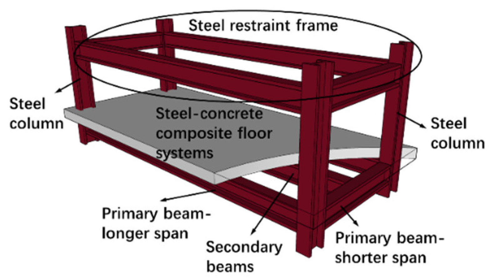
The tested model of the SCCF system is shown in
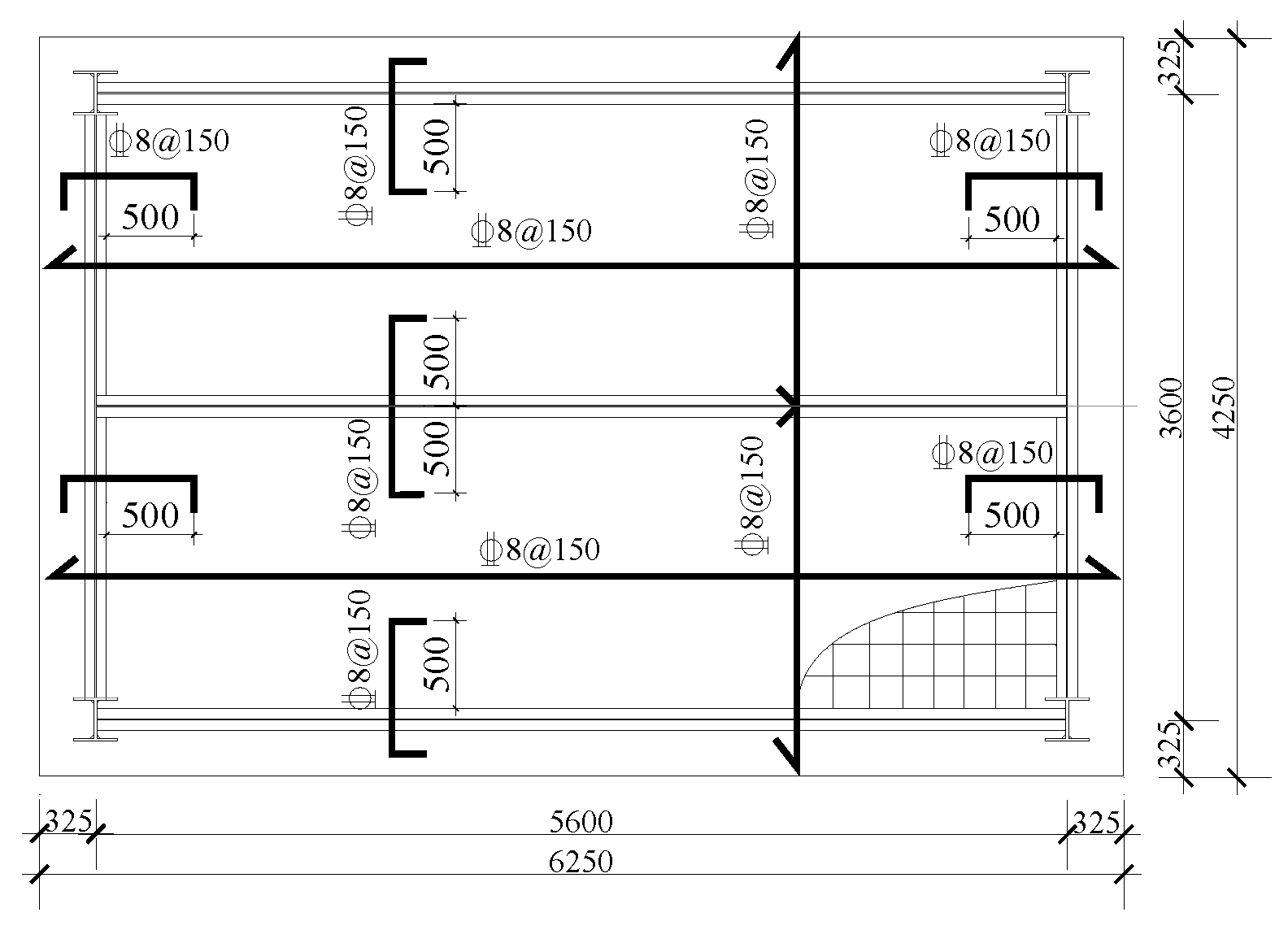
Figure 1, and Figure2 depicts the dimensions and reinforcement of the concrete slabs. Additionally, the model was placed on a furnace and its installation is shown in
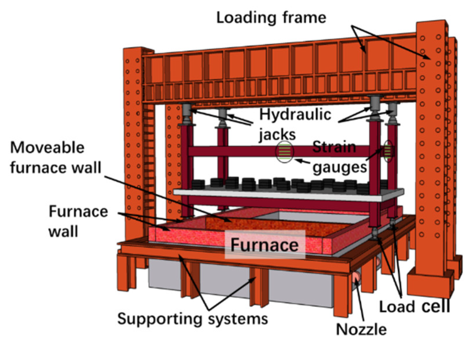
Figure 3. Four jacks were placed on the top of each column to apply the upper loads from the above floors, to simulate the actual working condition. Five strain gauges were arranged along the height of both long-span and short-span beams in the steel restraint frame, as shown in
Figure 3.
The internal forces (the axial force and bending moment) within the cross section of the steel beams can be calculated using the obtained strain data of the steel beams. Several deflection transducers were arranged on the top surface of the concrete slabs. During the test, the mentioned steel restraint frame is not exposed to fire directly and is located above the furnace to simulate the surrounding structure. The bottom secondary beams are located underneath the concrete slab and exposed to fire directly.
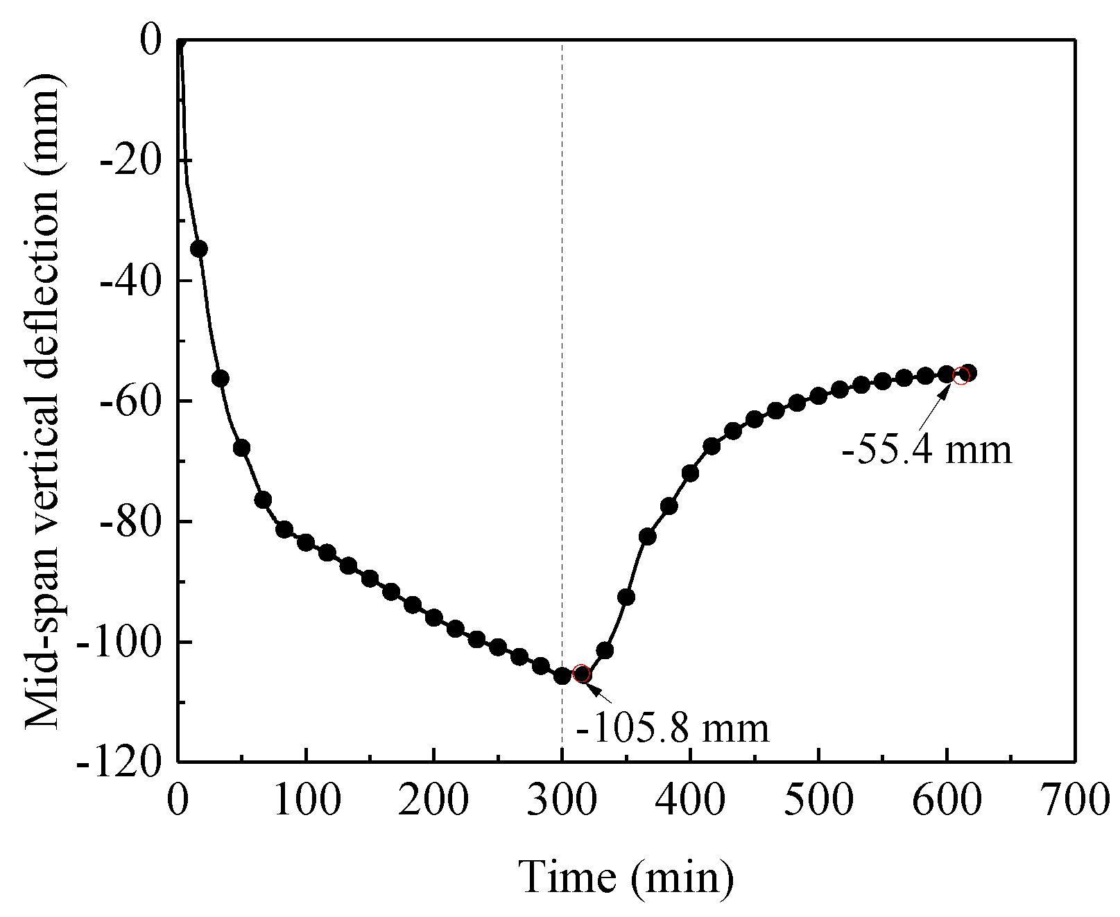
When the SCCF system was exposed to fire for 300 minutes and the temperature at the top surface of concrete slabs exceeded 180°C, it was considered that the SCCF system reached its insulation criteria and the fire test was terminated. Simultaneously, the correlation curve between the mid-span deflection of the concrete slabs and the fire duration is shown in
Figure 4. According to Chinese testing standards, if the maximum deflection of the concrete slabs exceeds 1/50 of the short-span length (i.e., 3600mm/50=72mm), it is considered that the concrete slabs is no longer suitable to continue bearing external loads. When the furnace was terminated, the maximum deflection of the composite floor slabs reached 105.8mm, and no sign of penetrating cracks and collapse phenomena were observed.
The test showed the general results at the present analytical paradigm. However, there is a lack of determination of the important characteristic points in the working process of the SCCF system. It is well known that the failure of a structure is a process, and this process should have a beginning point and an end point. Rationally, the existence of structural failure starting point is an undeniable fact, and it can be inferred that structural response data should contain some information to reflect the failure starting point. However, the current structural analysis could not find out or does not try to detect this essential characteristic point. Zhou [
29] indicated that only the new theory could reveal structural failure starting point from the tested data.
4. Stressing State Analysis of SCCF Systems in Fire
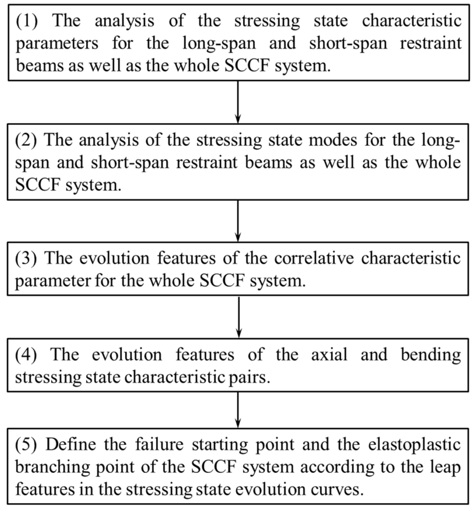
To present the stressing state analysis of the tested data for the SCCF system clearly,
Figure 5 illustrates the analytical items and route.
4.1. The Evolution Features of Stressing State Characteristic Parameters
By using Equation (13), the stressing state characteristic parameters for the long-span and short-span restraint beams,
EjL and
EjS, can be are calculated separately
Then, the sum of
EjL and
EjS values is taken as the characteristic parameter of the whole steel restraint frame,
Ej=
EjL+
EjS.
Ejcan be normalized to get the characteristic parameter
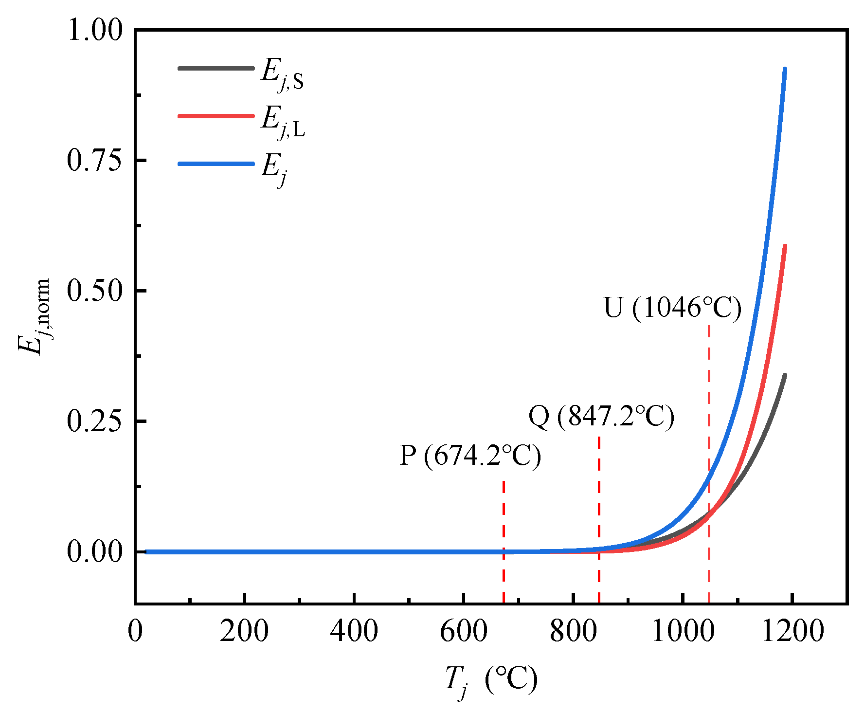
Ej,norm. Thus, the evolution curve of
Ej,norm with temperature
Tj can be plotted in
Figure 6, together with the
EjL-
Tj and
EjS-
Tj curves. As shown in
Figure 6, three typical leap points P, Q and U, are detected by applying the M-K criterion. It can be seen that the curve remains essentially flat before the temperature reaches the characteristic point Q, indicating that there is no significant change in the stressing state evolution of the SCCF system, and the structure is still in the elastoplastic working stage. After the temperature exceeds point Q, the slopes of the
Ej,norm-
Tj、
EjL-
Tj and
EjS-
Tj curves increase gradually. It is indicated that the overall stressing state of the SCCF system begins to take place a qualitative change and the SCCF system enters the failure stage. When the temperature reaches point U, the slopes of the three curves increase sharply, and the values of
EjL exceed those of
EjS simultaneously. It means that a qualitative change takes place again in the stressing state evolution of the SCCF system, indicating that point U could be a progressive failure point. In a word, the trending change of the characteristic parameter values for the upper steel restraint frame implies that the SCCF system starts to enter the failure stage. Eventually, the temperature of the top surface of the concrete slabs reaches the insulation failure criterion, and the fire test is terminated after 300 minutes. According to structural stressing state theory, the leap points P, Q and U during the entire fire exposure process can be defined as the elastoplastic branching point (
TP= 674.2°C,
tP=10min), the failure starting point (
TQ=847.2°C,
tQ=31min) and the progressive failure point (
TU=1046°C,
tU=117.2min), respectively.
4.2. The Evolution Features of Stressing State Modes
By utilizing the strain data collected from the long-span and short-span beams of the upper steel restraint frame, as well as the GSED values as stressing state characteristic parameters, a stressing state mode is conducted on the SCCF system under fire conditions. The jump feature of the stressing state is verified, and a detailed analysis of the stressing state of composite floor system is provided, revealing the changes of the stressing state when the SCCF system undergoes large deflection in fire.
The GSED values of each strain gauge on the long-span and short-span beams are calculated by Equations (14) and (15), and combined with the value of GSED calculated earlier,
Ej=
EjL+
EjS. Then, using Equations (16) and (17), the proportion of the GSED value of an individual strain gauge point to the
Ej, denoted as
βjL and
βjS, are calculated. Taking
βjL and
βjS as state variables to construct the stressing state mode
Mj, as defined in Equation (18). The correlation curves between
βjL,
βjS and the temperature
Tj are plotted in
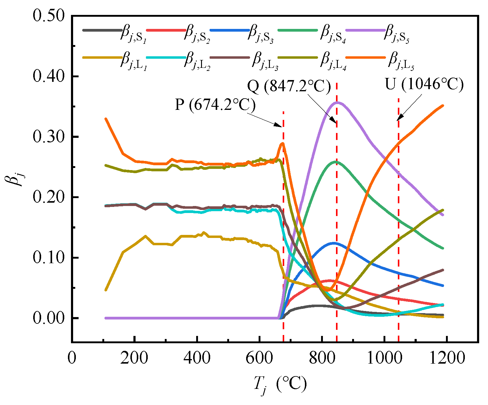
Figure 7, which represent the evolution process of the stressing state mode
Mjalong with the increase of the temperature.
As shown in
Figure 7, the state variables
βj maintains the trend without mutation before the temperature reaches elastoplastic branching point P (
TP= 674.2°C). Once the temperature exceeds point P, the curves of
Mj-Tj exhibit a significant alteration and undergo a sharp increase or decrease, indicating that the load-bearing proportion between the long-span strip and short-span strip of the SCCF system is gradually changing as the temperature increases.
Subsequently, the values of the GSED proportion
βjS4 and
βjS5 at the short-span direction are rapidly increasing and reaching a peak at the failure starting point Q (
TQ=847.2°C), with both accounting for about 60% of the GSED sum. When the temperature exceeds the characteristic point Q, the values of
βjS4 and
βjS5 at the short-span direction begin to decrease, and the values of
βjL3,
βjL4, and
βjL5 at the long-span direction begin to increase gradually, but the GSED value of the short-span direction still accounts for a larger proportion. When the temperature exceeds the progressive failure point U (
TU=1046°C), three curves of the long-span direction,
βjL3,
βjL4, and
βjL5, begin to increase sharply. Hence, a turning point (P, Q ,U) appears, and it implies an intrinsic change in the load-bearing mechanism. It is evident that the constructed stressing state mode curve
Mj-Tj has verified the evolution characteristics of the stressing state parameter curve of
Ej,norm-
Tj.
4.3. The Evolution Feature of Correlative Characteristic Parameter
The GSED values for the long-span and short-span restrained beams,
EjL and
EjS, have been obtained in Section 3.2. Based on these two values, a new stressing state mode is constructed as following, that is the ratio and the difference of
EjL and
EjS,
The correlation curves of
EjRatio-
Tj and
EjDV-
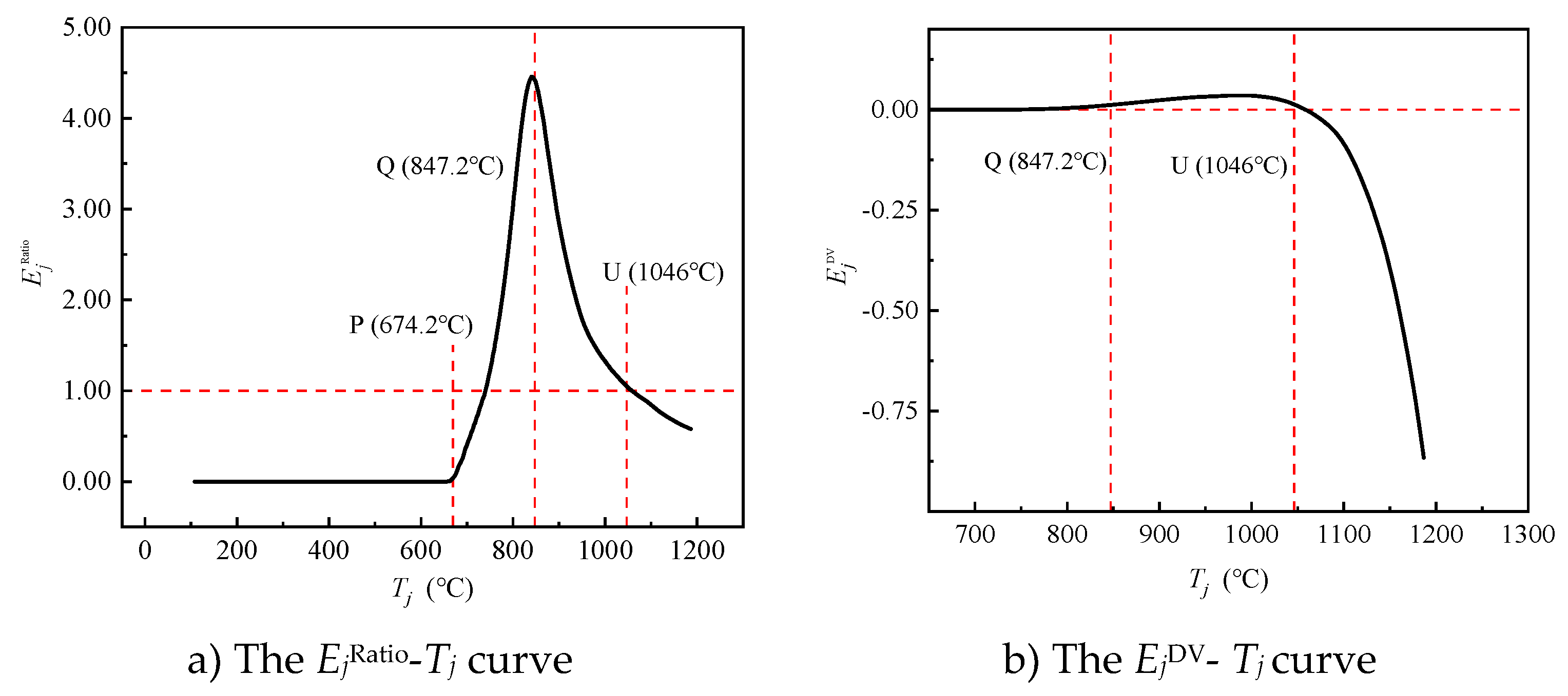
Tj are plotted in
Figure 8. These two curves remain horizontal without significant change until the temperature reaches point P (
TP= 674.2°C), indicating that the stressing state of the long-span and short-span steel beams are essentially in the similar working conditions. Subsequently, the curve of
EjRatio-
Tj exhibits an increasing trend until the temperature reaches the characteristic point Q (
TQ=847.2°C), where a transformation occurs and begins to decrease gradually. When the temperature is located at the interval between points Q and U, although the curve shows a downward trend rapidly, the characteristic parameter value of the long-span steel beam remains greater than that of the short-span steel beam during this phase. When the temperature exceeds the progressive failure point U (
TU=1046°C), the value of
EjRatio begins to fall below 1.0, indicating that the stressing state characteristic values of the long-span steel beam start to surpass the value of the short-span steel beam. In other word, the long-span strip of the concrete slab starts to carry more external load than short-span strip.
Similarly, the curve of
EjDV-
Tj, as shown in
Figure 8(b), exhibits significant changes at the characteristic points Q and U, displaying the process of the change in relative magnitude of the characteristic parameter values of the long-span steel beams and the short-span steel beams. It is demonstrated that the evolution feature of the load-bearing mechanism of the SCCF system when subjected to fire.
4.4. The Evolution Features of Axial and Bending Stressing State Characteristic Pairs
4.4.1. The Evolution Features of axial and Bending Stressing State Characteristic Parameters
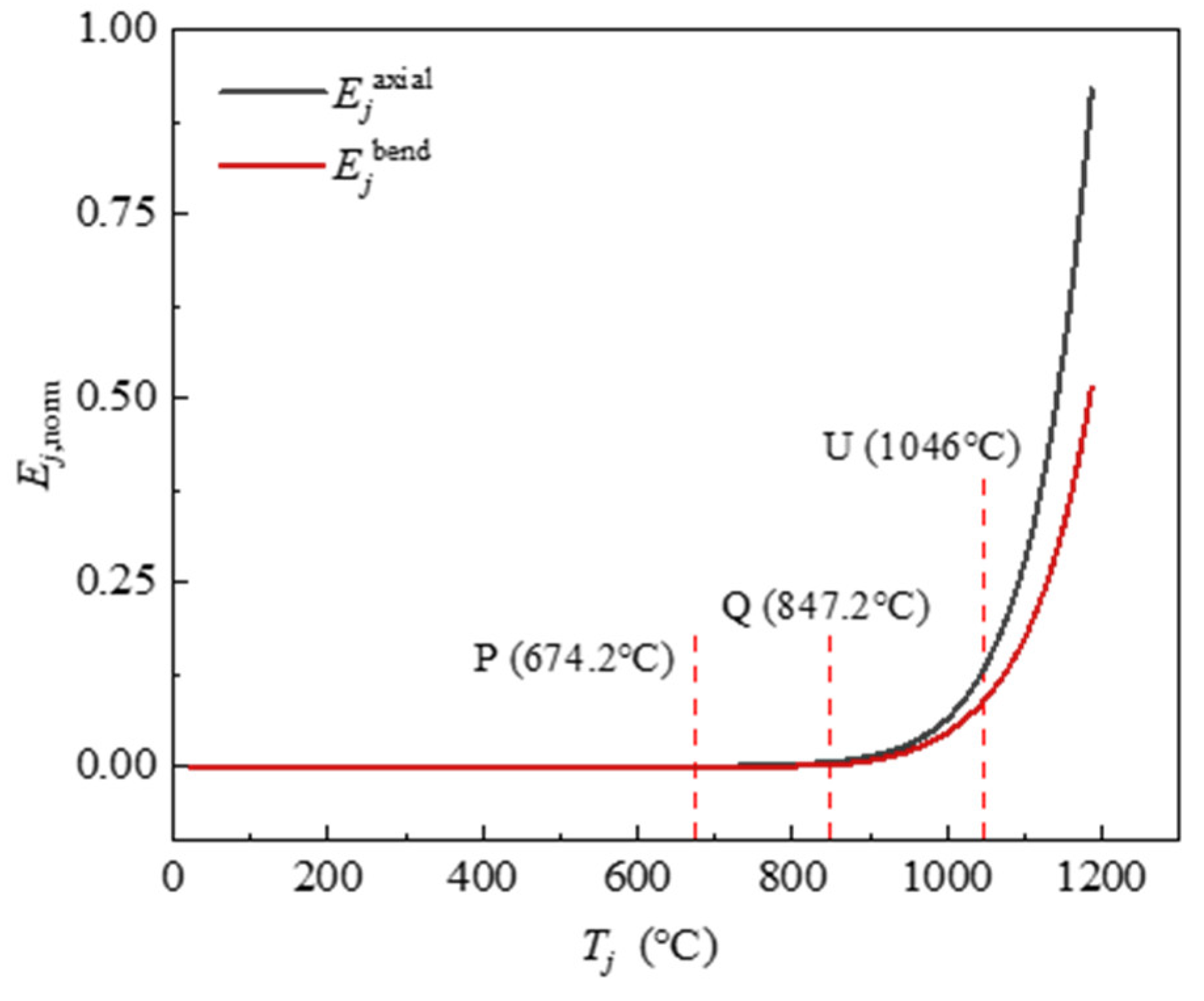
The GSED values generated by the axial force and bending moment on the cross-section of the upper steel beams are taken as the state variables, forming the corresponding stressing state characteristic parameters, that is,
where,
εjaxial is the average strain of cross section of the upper steel beam,
Ejaxial is the average axial generalized strain energy density of the cross section of the steel beam for both the long span and short span;
εjbend is the average bending strain of the steel beam’s cross section, and
Ejbend is the average bending generalized strain energy density of the steel beam’s cross section for both the long span and short span.
Figure 9 illustrates the correlation curves of the axial stressing state characteristic parameter
Ejaxial and the bending state characteristic parameter
Ejbend for the steel beams, along with the increasing of the temperature
Tj. As shown, these curves begin to exhibit trending changes at point Q. When the temperature continues to rise up to point U, the curves start to increase rapidly, and the value of axial stressing state characteristic parameter is always larger than that of the bending stressing state characteristic parameter throughout the later process.
4.4.2. The Evolution Features of Axial and Bending Stressing State Modes
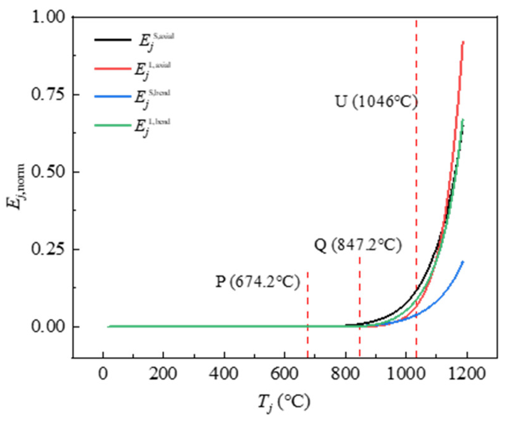
Equations (20) and (21) are used to calculate the axial generalized strain energy (
EjS,axial、
EjL,axial) and bending generalized strain energy (
EjS,bend、
EjL,bend) for the long-span and short-span beams, respectively. Meanwhile, these state variables form the overall stressing state mode of the SCCF system as illustrated by Equation (22),
where,
Eja,b=
Ejaxial +
Ejbend。
Figure 10 depicts the
Mjab -
Tj curves, and it can be seen that all the curves remain horizontal before point Q, and it means the SCCF system is in a stable working condition. However, it exhibits a trend change beyond point Q, with these curves starting to diverge from each other. Among the four curves, the first one to show an upward trend is
EjS,axial, followed by
EjL,axial and
EjL,bend at the long-span direction, which implies that relative significant deflection occurs along the short-span direction of the SCCF system, causing the upper short-span steel beams subjected to a significant compression and internal forces of the cross section firstly, and then the same mechanical response appeared followed by the long-span steel beams.
When the temperature reaches point U, all the curves have a more significant transitional feature and rise rapidly. Specifically, EjL,axial and EjL,bend show the fastest growth trend and reach a large value, while the trend of EjS,bend grows slower. These features reflect that the strain energy along the long-span direction accumulates significantly more than that along the short-span direction, which also illustrates the evolution of the stressing state mode.
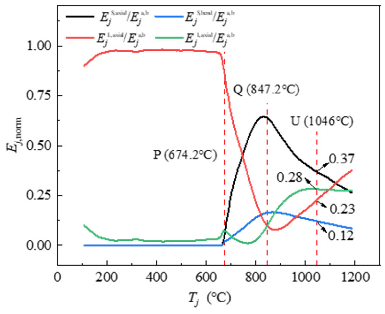
Figure 11 presents the
Rjab-
Tj curves, and it is observed that the curves remain straight before elastoplastic branching point P (
TP= 674.2°C), indicating that the upper steel frame has not yet begun to provide its constraint effect at a relative lower temperature.
When the temperature exceeds point P, the proportion of axial and bending GSED for the long-span steel beam starts to decrease, while the proportion for the short-span beam begins to increase, indicating that the SCCF system starts to deform due to fire exposure, along with the short-span strip beginning to bear the external load and showing visible deflection. At the failure starting point Q (TQ=847.2°C), the proportion of axial GSED of long-span and short-span steel beams reaches an extreme value. At the moment, the axial GSED proportion of the short-span steel beam exceed 60%, and it is indicated that the short-span strip of the concrete slab is the dominating load-bearing element. When entering the Q-U intervals, the curves show a reverse trend and begin to converge gradually, i.e., the percentage of each part tends to equalize. When the temperature reaches the progressive failure point U (TU=1046°C), it is evident that the ratio of axial strain energy density and bending strain energy density at the long-span direction exceeds 60% of the total value and continues to increase until the fire test was terminated, indicating that the long-span strip is becoming the primary load-bearing element. In other words, the proportion of the internal force at the short-span direction is diminishing, and the one at the long-span direction is growing simultaneously.
In summary, two stressing state modes above all exhibit characteristics of the evolution of the stressing state, demonstrating the corresponding features of the elastoplastic branch point and the earlier failure point.
4.4.3. The Evolution Features of Axial Stressing State Characteristic Parameter
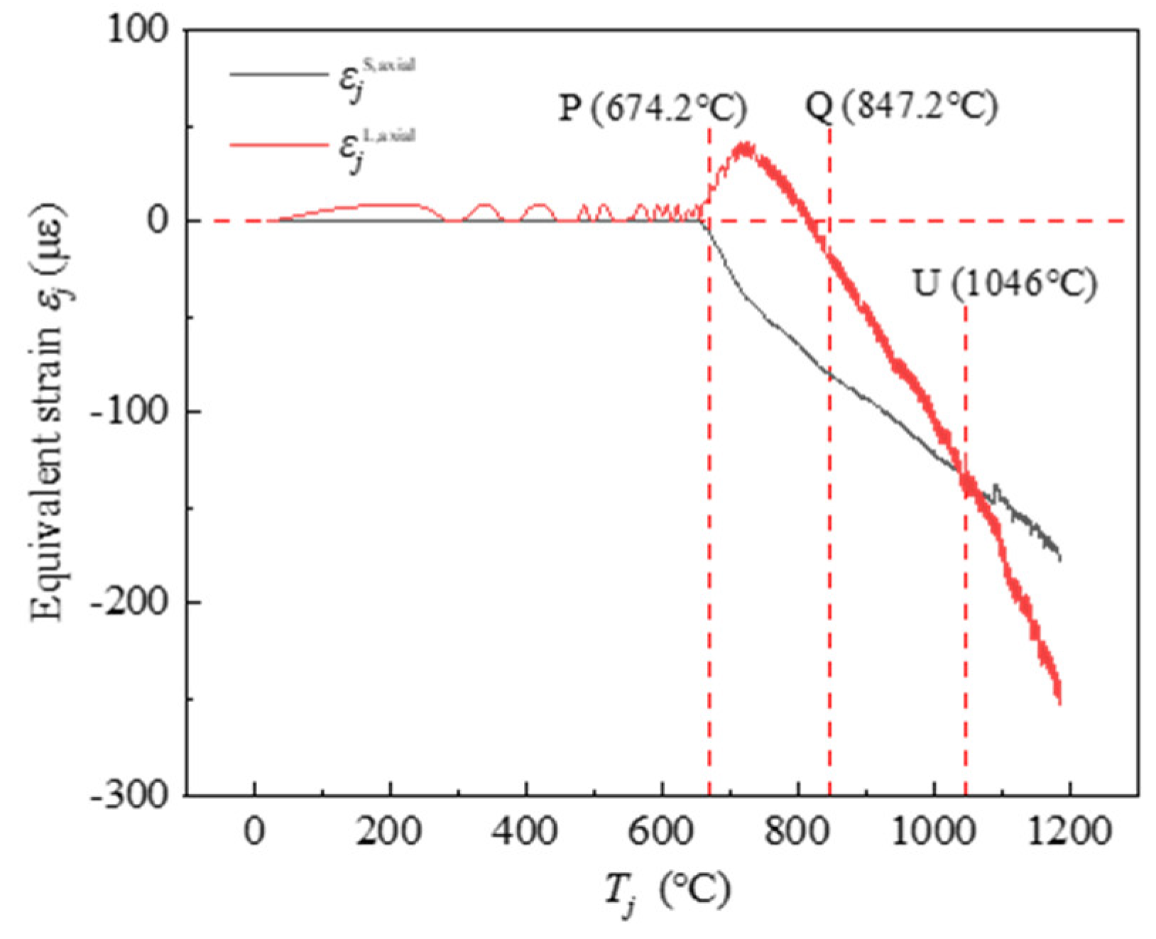
The long-span and short-span equivalent strain calculated by Equation (20), denoted as
εjL, axial and
εjS, axial respectively, are used as the stressing state characteristic parameters directly. Alternatively, these parameters can be taken as state variables to form the stressing state mode of the SCCF system to investigate their variation with the increase of the temperature
Tj, i.e., the evolution curve of stressing state of the SCCF system, as shown in
Figure 12.
It can be seen that before the point P, the value of εjS, axial is basically unchanged, and εjL, axial shows fluctuating change. In a word, there is no significant change generally. When the temperature exceeds 674.2°C, the equivalent strain εjL, axial at the long-span direction showed a growth trend and then decreased (always tensile strain), while the strain εjS, axial in the short-span direction gradually increased and showed a compressive strain. This is mainly due to the expansion deformation in the long-span direction is more obvious than that in the short-span direction, which makes the cross-section of the long-span beam show a tensile force state.
When the temperature increases to point Q, the deflection in the SCCF system start to increase gradually, and the long-direction steel beams of the upper steel restraint frames are squeezed simultaneously. Hence, the internal force of the cross-section of the long-span steel beams transforms into pressure eventually. Subsequently, the equivalent strain on the steel frame cross-section of both long and short spans maintains an increasing trend, but the growth rate of the long span is larger than that of the short span. When the curve develops to the characteristic point U, the equivalent strain in the direction of the long span begins to exceed the value of the equivalent strain in the direction of the short span, and a turning point appears, indicating that the stressing state of the SCCF system has changed.
Emphatically, if the provided stressing state characteristic pair does not reveal the leap features at these points clearly, it may be that the adopted method is unsuitable for this case. Anyway, a proper method can be proposed to evidently present the failure starting point and elastoplastic branching points. The construction of state variables, stressing state modes, and stressing state characteristic parameters is quite flexible and not confined to a fixed approach. However, there is one basic goal to create characteristic curves of the structural stressing state characteristic pair, which is able to demonstrate the leap features at the points of failure starting and elastoplastic branching clearly.
5. Conclusions
Structural stressing state analysis is firstly applied to reveal the evolution characteristics of the load-bearing processes of the SCCF system under fire. The achieved results can draw the following conclusions:
The SCCF system under a fire process certainly presents the failure starting characteristics, complying with the natural law from quantitative change to qualitative change of any system. The failure starting point exists in the tested strain data, which needs the proper methods for modeling the tested strain data. The methods include those for transferring the strain data into state variables, constructing stressing modes and characteristic parameters, as well as the criterion (such as the M-K criterion) for judging the leap points in the evolution curves of characteristic parameters. The failure starting points provide the reference to the accurate estimation of safety and the accurate/rational design for the SCCF systems in fire.
The SCCF system under a fire process also presents the definite elastoplastic branching characteristics. Similarly, this needs the proper stressing state modeling methods to position the elastoplastic branching points in the evolution curves of the stressing state characteristic parameters made by the tested strain data. The elastoplastic branching point also lays the new foundation to achieve the accurate/reliable design codes of the SCCF systems in fire. The fire resistant design based on the elastoplastic branching characteristic has two margins of safety: one from the elastoplastic branching point to the failure starting point and the other from the failure starting point to the ultimate point. The former is definite and the latter is semi-definite, which could greatly improve the fire resistant performance design of SCCF systems.
Also, structural stressing state analysis in this study indicates: At the early stage of a fire, the composite floor slabs primarily rely on the short-span strip to bear external loads. As the duration of fire exposure increases, the main direction of load-bearing gradually shifts to the long-span strip of the composite floor slabs. The critical point transition in the entire fire process can be presented through structural stressing states analysis, which provides an important reference to the fire resistant analysis and design of SCCF systems.
In a word, this study also indicates that the tested strain data of the SCCF systems undergoing the fire process still have some working law which has not been discovered by the existing theories and methods. Structural stressing state theory and methods presented in this study provide a reference to the stressing state modeling and analysis of similar structures in fire.
Author Contributions
Conceptualization, H.W.; Data curation, J.Q. and K.W.; Formal analysis, J.Q. and G.Z.; Funding acquisition, D.Z. and H.W.; Methodology, D.Z., Y.D. and G.Z.; Project administration, H.W.; Software, H.W.; Supervision, D.Z. and G.Z.; Visualization, K.W.; Writing – original draft, J.Q., H.W. and K.W.; Writing – review & editing, D.Z. and Y.D.
Funding
This research was funded by the Natural Science Foundation of Fujian Province, China (Grant No. 2023J01107), and Young and Middle-aged Teachers’ Education Science Research Project of Fujian Province, China (Grant No. JAT210570).
Acknowledgments
This study was supported financially by the Natural Science Foundation of Fujian Province, China (Grant No. 2023J01107), and Young and Middle-aged Teachers’ Education Science Research Project of Fujian Province, China (Grant No. JAT210570).
Conflicts of Interest
The authors declare no conflict of interest.
References
- O’Connor, M. Behaviour of a multi-storey composite steel framed building in fire. Struct. Eng. 2003, 81, 27–36. [Google Scholar]
- Lennon, T.; Moore, D.B.; Bailey, C. The behaviour of full-scale steel-framed buildings subjected to compartment fires. Struct. Eng. 1999, 77, 15–21. [Google Scholar]
- Bailey, C.G.; Toh, W.S. Small-scale concrete slab tests at ambient and elevated temperatures. Eng. Struct. 2007, 29, 2775–2791. [Google Scholar] [CrossRef]
- Fostera, S.J.; Baileyb, C.G.; Burgessa, I.W.; Plankc, R.J. Experimental behaviour of concrete floor slabs at large displacements. Eng. Struct. 2004, 26, 1231–1247. [Google Scholar] [CrossRef]
- Lim, L.C.S.; Wade, C.A. Experimental fire tests of two-way concrete slabs; School of Engineering, University of Canterbury: New Zealand, 2002. [Google Scholar]
- Dong, Y.L.; Zhu, C.J. Limit load carrying capacity of two-way slabs with two edges clamped and two edges simply supported in fire. J. Struct. Eng. 2011, 137, 1182–1192. [Google Scholar] [CrossRef]
- Zhang, D.S.; Dong, Y.L.; Fang, Y.Y. Behaviour of full-scale two-way simply supported concrete slabs in fire. Mag. Concr. Res. 2014, 66, 836–844. [Google Scholar] [CrossRef]
- Thienpont, T.; De Corte, W.; Caspeele, R.; Van Coile, R. Fire resistance and associated failure modes of axially restrained hollow core slabs. Fire Saf. J. 2023, 139, 103827. [Google Scholar] [CrossRef]
- Du, L.P.; Ji, X.P.; Wang, Y.X.; Han, F.Y.; Lu, K.W.; Wang, J.Q. Experimental study on thermal behaviors of two-layered functionally graded concrete slabs subjected to fire. Eng. Struct. 2023, 297, 117047. [Google Scholar] [CrossRef]
- Bolina, F.L.; Schallenberger, M.; Carvalho, H. Experimental and numerical evaluation of RC ribbed slabs in fire conditions. Structures. 2023, 51, 747–759. [Google Scholar] [CrossRef]
- Hua, N.; Khorasani, N.E.; Tessari, A.; Ranade, R. Experimental study of fire damage to reinforced concrete tunnel slabs. Fire Saf. J. 2022, 127, 103504. [Google Scholar] [CrossRef]
- Wang, Y.; Ren, Z.Q.; Huang, Z.H.; Gao, W.Y.; Zhong, B.; Bu, Y.X. , et al. Experimental and numerical studies of six small-scale continuous concrete slabs subjected to travelling fires. Eng. Struct. 2021, 236, 112069. [Google Scholar] [CrossRef]
- Wang, Y.; Bisby, L.A.; Wang, T.Y.; Yuan, G.L.; Baharudin, E. Fire behaviour of reinforced concrete slabs under combined biaxial in-plane and out-of-plane loads. Fire Saf. J. 2018, 96, 27–45. [Google Scholar] [CrossRef]
- Lim, L.; Buchanan, A.; Moss, P.; Franssen, J.M. Numerical modelling of two-way reinforced concrete slabs in fire. Eng. Struct. 2004, 26, 1081–1091. [Google Scholar] [CrossRef]
- Jiang, L.M.; Orabi, M.A.; Jiang, J.; Usmani, A. Modelling concrete slabs subjected to fires using nonlinear layered shell elements and concrete damage-plasticity material. Eng. Struct. 2021, 234, 111977. [Google Scholar] [CrossRef]
- Wang, Y.; Yuan, G.L.; Huang, Z.H.; Lyu, J.L.; Li, Q.T.; Long, B.Y. Modelling of reinforced concrete slabs in fire. Fire Saf. J. 2018, 100, 171–185. [Google Scholar] [CrossRef]
- Khalaf, J.; Huang, Z.H. The bond behaviour of reinforced concrete members at elevated temperatures. Fire Saf. J. 2019, 103, 19–33. [Google Scholar] [CrossRef]
- Hawileh, R.A.; Kodur, V. Performance of reinforced concrete slabs under hydrocarbon fire exposure. Tunn. Undergr. Sp. Tech. 2018, 77, 177–187. [Google Scholar] [CrossRef]
- Qiu, J.; Jiang, L.M. An integrated section model to enable simulating composite slabs in fire simply as modelling a flat slab. Comput. Struct. 2023, 289, 107180. [Google Scholar] [CrossRef]
- Qiu, J.; Jiang, L.M.; Orabi, M.A.; Usmani, A.; Li, G.Q. A computational approach for modelling composite slabs in fire within OpenSees framework. Eng. Struct. 2022, 255, 113909. [Google Scholar] [CrossRef]
- Hua, N.; Khorasani, N.E.; Tessari, A. Numerical modeling of the fire behavior of reinforced concrete tunnel slabs during heating and cooling. Eng. Struct. 2022, 258, 114135. [Google Scholar] [CrossRef]
- Jiang, J.; Li, G.Q. Parameters affecting tensile membrane action of reinforced concrete floors subjected to elevated temperatures. Fire Saf. J. 2018, 96, 59–73. [Google Scholar] [CrossRef]
- Bailey, C.G. Membrane action of unrestrained lightly reinforced concrete slabs at large displacements. Eng. Struct. 2001, 23, 470–483. [Google Scholar] [CrossRef]
- Dong, Y.L.; Fang, Y.Y. Determination of tensile membrane effects by segment equilibrium. Mag. Concr. Res. 2010, 62, 17–23. [Google Scholar] [CrossRef]
- Dong, Y.L. Tensile membrane effects of concrete slabs in fire. Mag. Concr. Res. 2010, 62, 497–505. [Google Scholar] [CrossRef]
- Qi, H.H.; Chen, S.Y.; Wang, Y.; Li, G.Q. Tensile membrane action of RC slabs and steel-concrete composite slabs at elevated temperatures. Eng. Struct. 2024, 299, 117098. [Google Scholar] [CrossRef]
- Jiang, J.; Qi, H.H.; Lu, Y.L.; Li, G.Q.; Chen, W.; Ye, J.H. A state-of-the-art review on tensile membrane action in reinforced concrete floors exposed to fire. J. Build. Eng. 2022, 45, 103502. [Google Scholar] [CrossRef]
- Jiang, J.; Pintar, A.; Weigand, J.M.; Main, J.A.; Sadek, F. Improved calculation method for insulation-based fire resistance of composite slabs. Fire Saf. J. 2019, 105, 144–153. [Google Scholar] [CrossRef]
- Zhou, G.C. Structural Stressing State Analysis Theory and its Applications; Harbin Institute of Technology Press: Harbin, China, 2020. [Google Scholar]
- Shi, J.; Li, W.T.; Zheng, K.K.; Yang, K.K.; Zhou, G.C. Experimental investigation into stressing state characteristics of large-curvature continuous steel box-girder bridge model. Constr. Build. Mater. 2018, 178, 574–583. [Google Scholar] [CrossRef]
- Liu, B.; Zhang, Y.; Li, R.; Zhou, G.; Zhao, Y. Essential stressing state features of spirally reinforced concrete short columns revealed by modeling experimental strain data. Structures. 2020, 25, 1–7. [Google Scholar] [CrossRef]
- Zhao, J.B.; Wang, Q.; Gong, Y.F.; Zhang, Y.N.; Zhou, G.C. Bending working law of corroded ductile iron pipe flange connections revealed by structural stressing state theory. Int. J. Pres. Ves. Pip. 2022, 199, 104717. [Google Scholar] [CrossRef]
- Chen, Z.H.; Zhao, Y.; Shao, Y.S.; Zhou, G.C. Essential state-of-stress features of HBBC connections revealed by modeling simulative strain energy. Eng. Struct. 2021, 230, 111463. [Google Scholar] [CrossRef]
- Zhou, G.C.; Shi, J.; Li, P.C.; Li, H.H. Characteristics of structural state of stress for steel frame in progressive collapse. J. Constr. Steel Res. 2019, 160, 444–456. [Google Scholar] [CrossRef]
- Zhang, D.; Lin, X.; Wang, H.; Dong, Y.; Zhang, J.; Hu, H. Experimental Investigation on Fire Behavior and Quantitative Restraint Forces of Steel-Concrete Composite Floor Systems. J. Struct. Eng. 2022, 148, 4022156. [Google Scholar] [CrossRef]
|
Disclaimer/Publisher’s Note: The statements, opinions and data contained in all publications are solely those of the individual author(s) and contributor(s) and not of MDPI and/or the editor(s). MDPI and/or the editor(s) disclaim responsibility for any injury to people or property resulting from any ideas, methods, instructions or products referred to in the content. |
© 2024 by the authors. Licensee MDPI, Basel, Switzerland. This article is an open access article distributed under the terms and conditions of the Creative Commons Attribution (CC BY) license (http://creativecommons.org/licenses/by/4.0/).
