Submitted:
08 May 2024
Posted:
09 May 2024
You are already at the latest version
Abstract
This study develops an intelligent fire suppression device that links microcapsule-based IoT to extinguish early fires, such as blind spots that cannot be seen by humans or places that are difficult to recognize fires. The microcapsule is a micro-unit collection that collects Novak 1230 gas generated in the semiconductor production process. The microcapsule is molded into a form with a fire suppression function, and when a fire occurs, the molded body explodes and absorbs ambient oxygen to suppress the fire. The complex sensor IoT executes smoke and heat detection generated when a fire is suppressed within 10 seconds, which derives the reliability of the detector by notifying the fire and detecting the ignition point through communication linkages such as Ieee 485 and WiFi or LoRa.
Keywords:
Complexed sensor IoT
; Microcapsule molded
; Intellectual fire extinguisher
; Fire detection
; Detection system
1. Introduction
The factors that cause the initial fire of the fire are various, such as electrical outlets, general distribution circuits, and oil vapor gas cluster spaces. In most cases, these places are out of reach of human hands or out of attention, causing the spread of fire by missing the initial suppression time in the event of a fire. In addition, the absence of suppression means in the early stages of a fire causes human and property disadvantages in missing the Golden Time. Figure 1 shows electrical facilities exposed to fire hazards due to dust or dust in companies or households.
Various fire extinguishing technologies have been developed to suppress fires. However, it is very difficult to respond to fires that have occurred in invisible underground distribution boards and outlets because they are used while the fire is expanded.Powder fire extinguishers are cheaper than other fire extinguishers, but they can be used only when a fire spreads, and secondary damage caused by drugs occurs. The CO2 fire extinguisher is a cooling injection method, which have heavy in weight, making it inconvenient to move, and secondary damage occurs due to frostbite when long-term spraying on the human body. Haron fire extinguishers are used in places of expensive facilities (computer room, machine room, storage room), but most of them are used when a fire spread. As an environmental substance that destroys the ozone layer, production will be discontinued in the future due to the discontinuation of drugs. Therefore, clean fire extinguishers are expensive as a substitute for Haron, and the supply of drugs is unstable[1].
Figure 2 shows a intricately connected multi-tab. After a long time of use, dust accumulated in the multi-tab causes a short circuit and causes a fire. In order to prevent this, the use of flame-retardant materials is mandatory, but it is difficult to completely block the spread of flame-retardant materials to surrounding flammable substances during firing.
Fire notifications and other alarm devices have many malfunctions, and fire trucks are often difficult to enter due to time and road conditions. In particular, even if fire trucks such as traditional markets and bathhouses, which have recently become a social issue, have entered, there are considerable difficulties in initially suppressing them due to the concentration of shopping centers or complex internal structures of buildings. Figure 3 shows a fire caused by an electric short circuit, (a) Greenfell Tower on the 24th floor of London, England, where 160 people died and went missing, 78 injured, 17 in critical condition, (b) Scenes of the fire inside the ESS device and the fire magnification, and (c) an apartment fire on the 84th floor of the Torch Tower in Dubai, UAE. This is an example of a fire that broke out on a high-rise and spread down on one side of the building. (d) It shows a fire disaster predicted by careless risk due to the structure of dry bit and piloti due to the fire in the bathhouse.
In this study, in order to overcome the problems and limitations of existing topic detection technology or sensor products, it is designed to execute an automatic fire extinguishing function in case of fire contact through a molding process encapsulating Novek 1230 gas as shown in Figure 3. The smoke detection signal generated during the fire extinguishing process is transmitted to the IoT terminal to access the national emergency contact network and perform fire suppression operations. At this time, a warning is given to fire departments, insurance companies, and related organizations by providing IP address information data that can identify the location of the fire extinguishing point and by making it possible to know the ignition point or cause according to the IP location.This makes it possible to effectively extinguish a fire by installing it in a place where many electric wires such as an electric outlet or a distribution panel are located, or where a fire may ignite. In particular, it implements a system that can effectively cope with the case of ignition taking advantage of sleeping time at night.
2. IoT-Based Intelligent Microcapsule Composite Device
2.1. Microcapsule Composite Material
The microcapsule extinguishing agent is made of adhesive paste composites such as ABS and PC, and when firing, the fire suppression operation is performed with an immediate explosion within 10 seconds. Figure 4 shows the process of collecting Novec 1230 gas in a microcapsule [2].
The microcapsule molded body is maintained for a long period of time, has a 90-95% fire extinguishing function even when stored for several years, and has a high waterproof effect. The microcapsule composition occupies more than 80% of the material, and instantaneously explodes at a set temperature of 110 to 165°C to suppress a fire [3]. Figure 5 shows various types of applied molded articles using microcapsules. Table 1 shows the material specifications constituting the microcapsule.
When the fire suppression device is installed close to the fire area of the distribution panel, fire will occur within 10 seconds in case of a fire. It suppresses ash. Pad and cord-type fire extinguishing products can be easily installed in a narrow space (2-3 mm) without special facilities or construction, and can be applied to various targets. In particular, it is easy for the general public to install, and it can be used not only for new facilities but also for various exposure to old industrial sites, public places, buses, and schools with high risk factors. Figure 6 shows an example of a cord and pad sticker, and a cord and pad mixed installation.
2.2. Sensor IoT Composited Device
Figure 7 shows the control diagram for controlling the microcapsule in case of fire contact. The temperature at which the capsule bursts is 110~165℃, which is the same as the fire temperature, and a heating wire is wound around the capsule and current flows to heat it to 200℃ or higher so that the capsule bursts [4]. Nichrome wire is used as a heating wire, and it can generate heat at 200℃ or higher within 10 seconds, and it is implemented so that it can generate heat even when supplied with a lithium ion battery.
Figure 7.
Control diagram for controlling the microcapsule
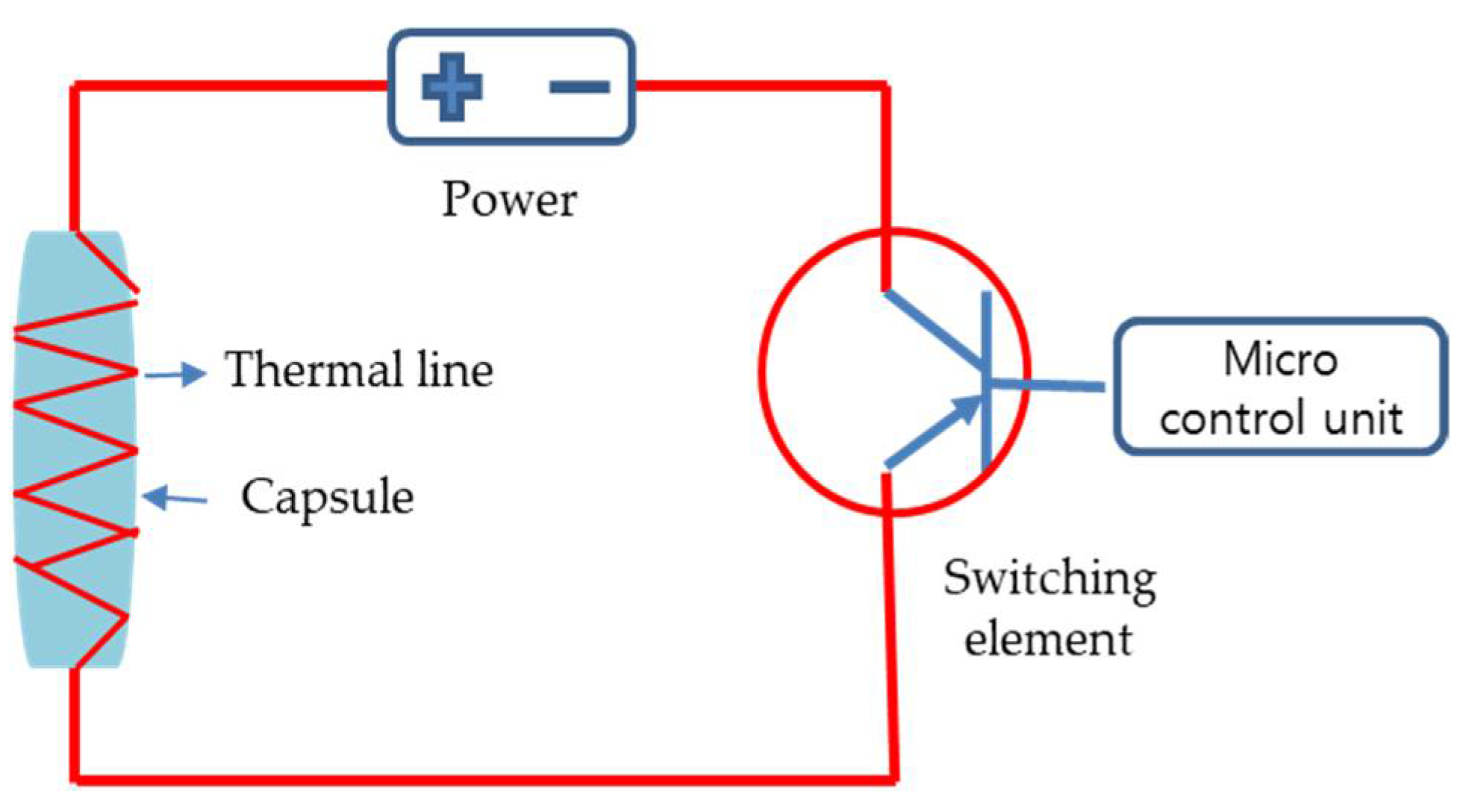
Figure 8 shows the implementation of an IOT circuit that processes signals detected from sensors. It consists of a microcontrol unit (MCU) that controls the received signal and SPI that connects the peripheral sensing function, GPIO, UART, and wireless LoRa. The program editor and downloader use the CodeVision AVR standard, AVR Studio Programmer [5]
Figure 7.
Implementation of an IOT circuit that processes signals detected.
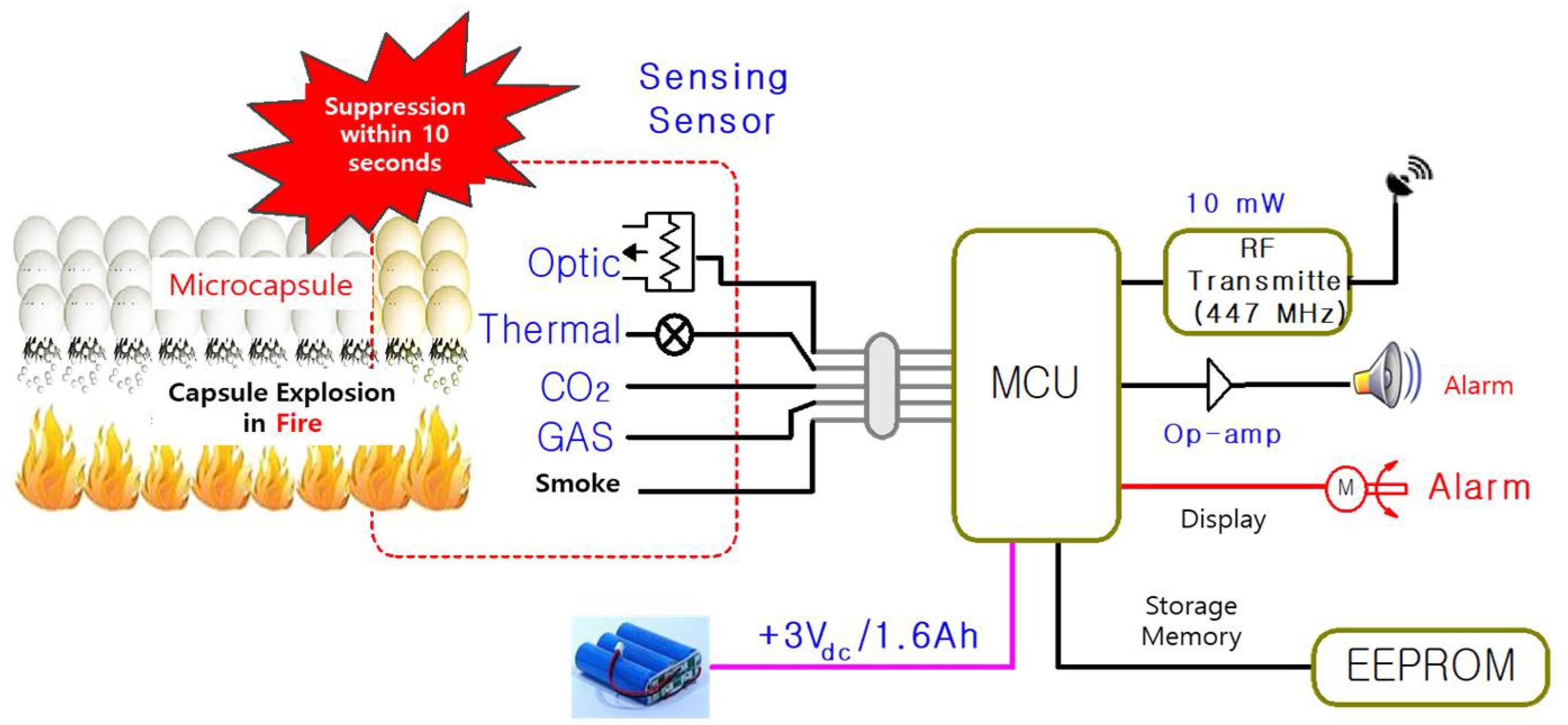
In Figure 7, the circuit unit that processes multiple sensor signals on the input side detects the fire temperature, CO2, GAS, and smoke, and collects sensor data. At this time, the sensor data conversion unit that checks the power required of each sensor and the transmission/reception unit that transmits and receives are followed. The MCU control unit (mesh network configuration) controls multi-sensor data control, network configuration between modules, risk warnings, and messages, and manages the radio control unit that transmits messages wirelessly. The radio control unit transmits data through an antenna connection [6].
Figure 8 shows the configuration of the UART and the main MCU board in a form that can be combined or detached by cable. It can be installed anywhere inside the distribution panel using a bracket. It is also possible to prevent direct damage from fire by installing the main MCU board outside the distribution panel. UART is an integrated circuit that asynchronously communicates parallel data of the MCU as serial data. In the 8-bit data format, it is promised that synchronization signals can be found on the receiving side to process the start and end of the data in time [7]. The 14 GPIO operates in real time on the user connection unit, the PC operation unit, and the 32 KHz oscillator (x-tal). The SPI is connected to a wireless communication antenna using the Lora module. These functions are processed by a command processor linked by a communication protocol.
Figure 8.
Configuration of the uart and the main MCU board.
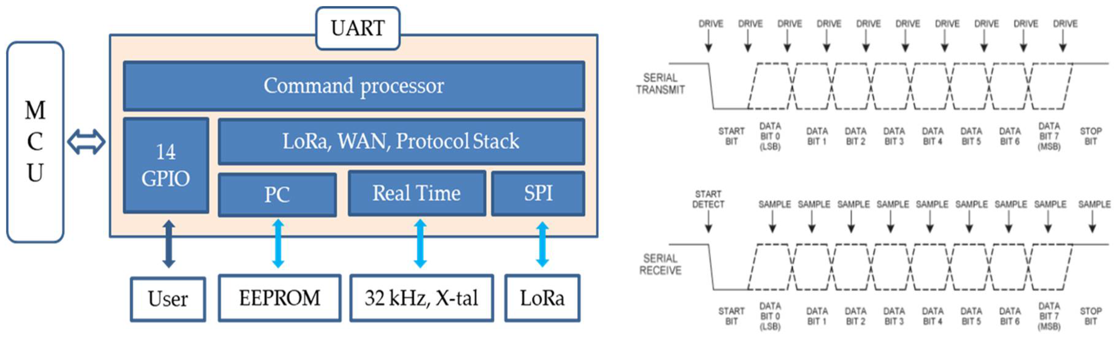
Figure 9 shows a fire detection fastener protocol between a fire breaking news machine and a long-distance IoT. The communication protocol initially consists of control statement signals (Start of Text, STX), module address, system status, alarm status, cycle error check (CRC), and end of text (ETX) [8]. The operation of the configuration bits will be described through the data bits performing each function.
Figure 10 shows the bracket to be installed on the electric distribution panel. The bracket is designed to allow the main MCU circuit board and sensor to be coupled or disconnected by a cable. The bracket is designed to be installed anywhere inside the distribution panel, and the main MCU board is installed outside the distribution panel to prevent direct damage from fire.
In addition, flame retardant PBT, PC/ABS, etc. are used as a protective measure against high temperatures, and since the heat deflection temperature is 70-130℃, it can last more than 2 minutes after the fire detection judgment is made, and communication and fire extinguishing are possible between them. Insulation such as air rogel is used in the IoT-based intelligent fire suppression unit using the internal microcapsule to design it to withstand more heat when the enclosure is insufficient. In addition, capacitors and IC components are selected and designed as products with strong heat resistance. Figure 11 shows a configuration example in which the main MCU PCB bracket is installed with the sensor position within the electric distribution panel.
Normally, the power of the product is supplied through an adapter and the battery is charged at the same time, and when the power supply is cut off in the event of a power outage, the battery operates to supply power
2.3. Implementation of IoT Installation Equipment and Communication Software
Figure 12 constitutes the entire fire alarm network. The automatic fire fastener first contacts the fire car station in the event of a fire, controls the emergency opening and closing of the building, and issues a fire occurrence alarm signal through the siren.
Recently, buildings are equipped with GR-type complex receivers. Most buildings are managed by building management monitoring, and GR complex receivers are also mounted. An automatic fire detection device is attached to the fire hydrant on each floor inside the building to indicate the occurrence of a fire and warn of an emergency. With the development of the national emergency contact network, drones play the role of observing and guiding complex topography, and recently, they perform tasks to observe fire occurrence areas in high-rise buildings [6].
3. Experimental Results
3.1. Smoke and Heat Sensing Performance Experiments
Figure 13 conducts an experiment to measure the air temperature inside the switchboard using a hot air fan at the lower part of the switchboard. The temperature of the hot air fan is set to 630°C and the initial temperature inside the switchboard is set to 26°C. It took about 7 minutes for the temperature to rise to 60°C, and a temperature rise curve is recorded and used to set the temperature rise width of the differential sensor [9].
Figure 15 models a rectangular parallelepiped-shaped distribution panel case with a width of 80 cm, a length of 25 cm, and a height of 160 cm as a fire model. Three rows are hung from the ceiling of the distribution panel at equal intervals, and three temperature sensors are installed evenly at equal intervals in each row, and the detector is installed at the upper left.
Figure 16 shows the temperature change of the sensor for each position in Figure 16. Here, the temperature at positions 7 and 4 is the highest. After that, 8, 1, and 2 were high, and the temperature at positions 3, 6, and 9 on the right was the lowest. Through this, it can be assumed that although the combustible material is located in the center inside the distribution panel, in the convection phenomenon by heat, the heated air tilts to the left and rises and falls to the right. It can be seen that the temperature in the detector rises steadily with an S-shaped conversion curve at a rate of about 48s to 2°C/min for about 3 minutes, and then falls again after a high point.
Figure 17 shows that the smoke density gradually increased from 48s in an irregular shape and reached more than 5 times the initial smoke density after about 20s, after which it converged to the high point uniformly. It is examined whether the flame sensor (infrared sensor) of the complex sensor installed in one upper corner of the distribution panel fire model can detect the flame generated from the fire source normally. Since the flame of the fire is detected by the complex sensor 6s after the measurement begins, and the flame sensor operates in the on-off contact method, it is possible to confirm the occurrence of the fire. Rather, it is reasonable to accept that there is a high possibility of fire due to the occurrence of sparks due to static electricity or short circuits.
The smoke sensor and temperature sensor test standards apply to the type approval and technical standards of the Korea Fire Protection Testing Institute (Fire Service Notice No. 2019-10), and the sensitivity test of the constant temperature sensor in Article 16 and the sensitivity test of the ionization sensor in Article 18 are applied mutatis mutandis. The temperature sensor malfunction test shall satisfy the performance conditions because it does not operate within 10 minutes at a temperature 10°C lower than the nominal operating temperature. Table 2 shows the results of the malfunction test of the temperature sensor and the smoke sensor.
The smoke sensor malfunction test shall not operate within t minutes in wind speed V cm/s airflow containing concentration smoke with a current change rate of 0.65 k. The smoke sensor operation test condition is 1.35 K = 1.35 x 0.24 = 0.324, and the test concentration (5~10%/m) = 100 x (0.324 -0.19) + 5 = 11.165%/m, and the operation test condition is 0.65 K = 0.65 x 0.24 = 0.156. It is calculated as the test concentration (0-5%/m) = 26.3 x 0.156 = 4.1028%/m. Therefore, if the ionization transformation rate of change to the smoke concentration (%/m) in the smoke sensor non-operation test, the performance condition within 5% is satisfied with 4.1028%/m.
3.2. Mobile Performance Evaluation by Sensor Behavior
Figure 18 develops an app for sensors and IoT control. To install an IoT device on a distribution panel (node), read the device information by reading data. Enter the content of the place to be installed, enter the phone number of the person in charge, and enter the required message [7]. These are required for module authentication and registration, module location, remote control and control.
Figure 19 shows a chamber test of antenna frequencies allocated for fire fighting and a case of communication distance performance by an antenna in an external environment. The specifications of 447Mhz_Sub-G Module development are shown in Table 3. And the electrical specifications of the product are shown in Table 4.
Figure 19 shows a chamber test of an antenna allocated for fire fighting and a case of communication performance distance by an antenna in an external environment [5].
Figure 20 shows a test that informs the mobile of fire information sent from the fire location when a fire occurs.
4. Conclusion
Most of the causes of property damage caused by fires are due to the absence of initial fire suppression means, narrow vehicle entry, and complex internal structures, missing the Golden Time of fire suppression. If a person is unable to reach or is far from attention, the location of the fire is initially identified to implement a system that can track the location of the fire along with the identification of the cause.
In this study, a Novec 1230-based microcapsule is used, and the stand alone type microcapsule built-in paste that can be automatically extinguished in the event of a fire through the development of an IoT sensing convergence module is constructed. It is effective in installing a convergence device that can be easily applied to the expected location of the fire, and suppressing the fire risk in the shaded area where the human view is not secured and the fire in the local fire occurrence location. The technical standards for type approval and product inspection of the Control Test Research Institute detector (Fire Service Notice No. 2019-10) were applied to the smoke sensor and temperature sensor test standards, and the sensitivity test of the constant temperature sensor and the sensitivity test of the ionization sensor of Article 18 were applied.
The temperature sensor non-operation test satisfies the performance condition because it does not operate within 10 minutes at a temperature 10°C lower than the nominal operating temperature. When the ionization conduction change rate is converted into smoke concentration (%/m) under the smoke sensor non-operation test condition, it is 4.1028%/m, which satisfies the performance condition within 5%. The wireless communication module that communicates with the IoT sensor fusion device has an indoor wireless distance of about 20 to 50 meters in the 447 MHz band, and can communicate more than 1 km outdoors (open field).
References
- National Fire Information System. Gyeonggi Disaster and Safety Headquarters National Fire System Analysis Data. Republic of Korea, 2016.
- S. S. Lee, C. Y. Jeong, Composition of Halogen-based Gas Extinguishing Agent and Method of Manufacturing the Same, 2017; Patent 10-1733423.
- D. H. Yoon, D. H. Lee, Development of IoT Sensing Technology Convergence Intelligent Fire Extinguishing System Using Microcapsule Digestives, Ministry of SMEs and Startups Technology Development Report, Republic of Korea, 2019. Authors.
- J. J. Kim et al., A Study on the Current Status and Problem Analysis of Flame Detectors, A Paper Collection of the Electronics Conference of Electricity, 2017; pp. 495-496.
- D. H. Lee et al., ECO-KICOX-03-SW Response Speed Self-Performance Evaluation, Ecosense Co. Ltd. 2020.
- K. H. Kim and 5 others, IEEE 802.15.4-based Ubiquitous Sensor Network Technology, Journal of the Korean Electronics Society, 2004; Volume 31, No. 12, pp.74-84.
- D. S. Kim et al. 3, Research on the Development of Hardware Location Recognition Engine Using the Maximum Likelihood Method for Location Recognition in IoT Network, Journal of the Korean Electronic Engineering Association, 2016; Volume 53, No.11, pp.32-49.
- J. S. Won, Electrical Fire (II) - Identification of Causes of Electrical Fire, Journal of the Korean Fire and Fire Society, 1988; Volume 2, No.1, pp.65-70.
- D. H. Yoon, Intelligent Fire Suppression System and Method of IoT Sensing Technology Convergence, 2019; Patent 10-1230217.
Figure 1.
Electrical facilities exposed to fire hazards due to dust.
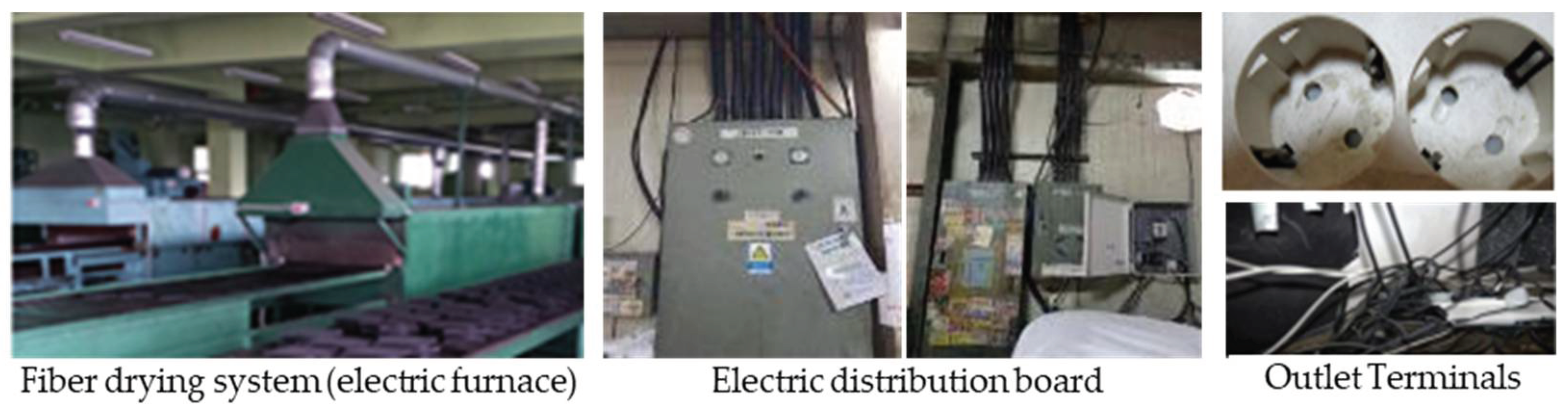
Figure 2.
Intricately connected multi-tab.
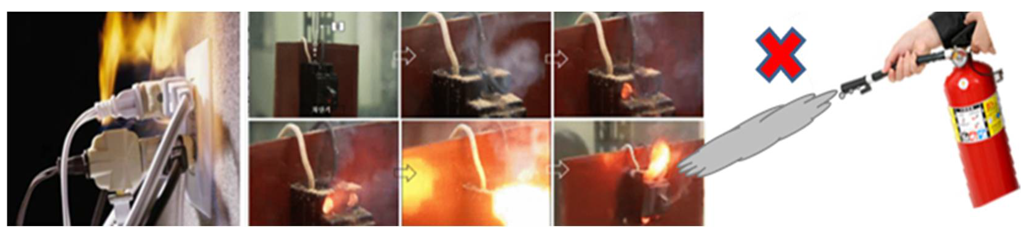
Figure 3.
Fire caused by an electric short circuit.
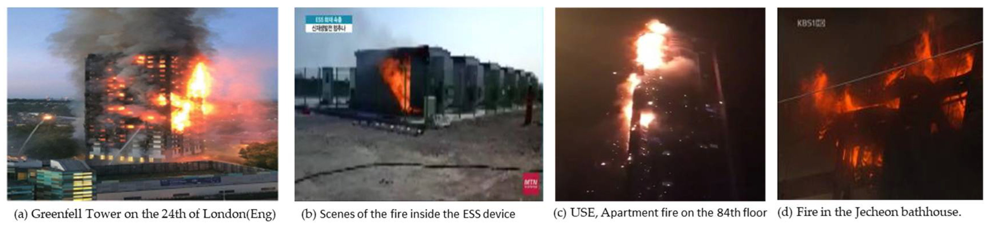
Figure 4.
The process of collecting Novec 1230 gas in a microcapsule.
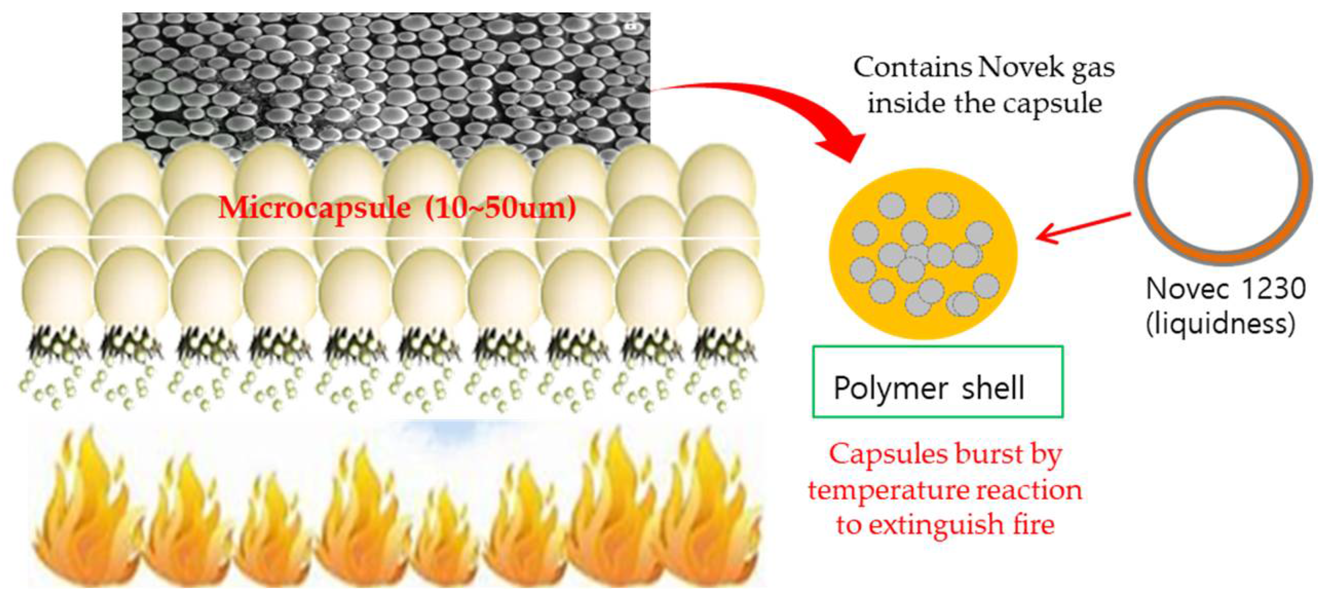
Figure 5.
Various types of applied molded articles using microcapsules.
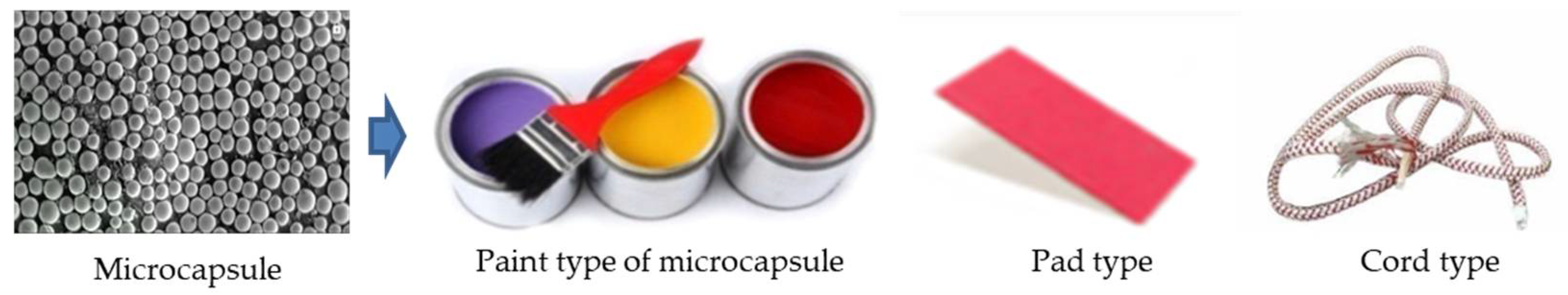
Figure 6.
Examples of cord and pad sticker installation.
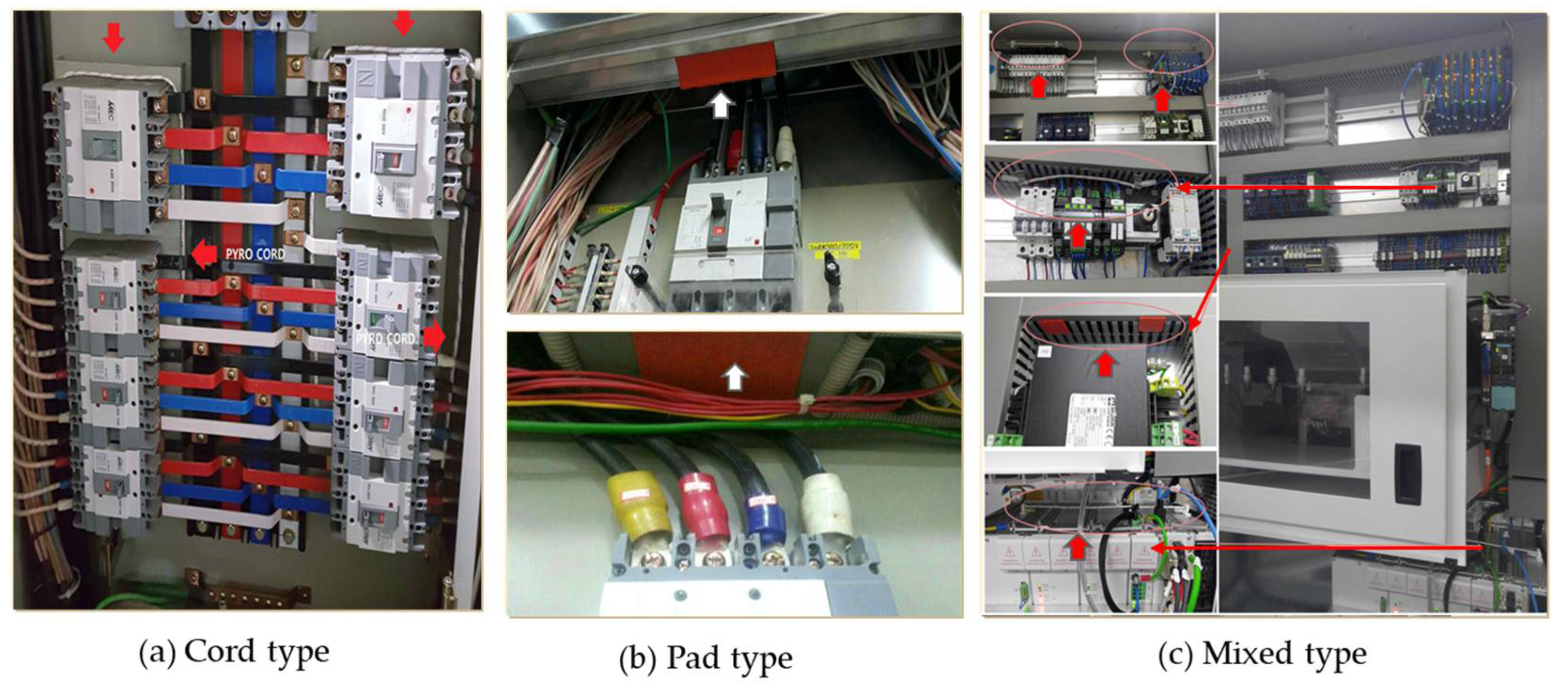
Figure 9.
Fire detection communication protocol.
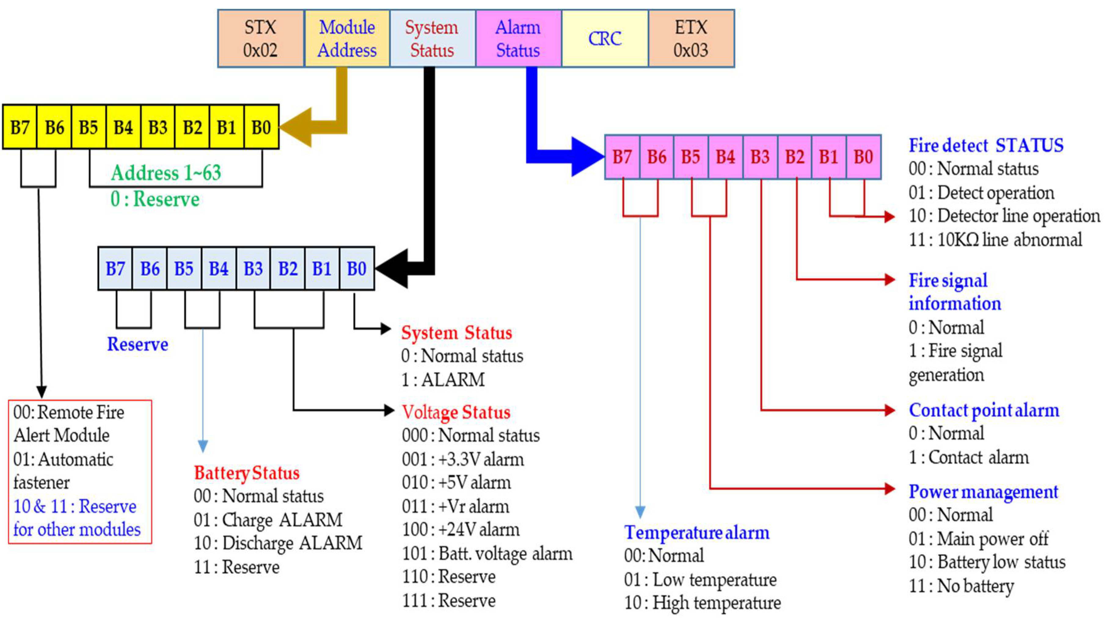
Figure 10.
Bracket to be installed on the electric distribution panel.
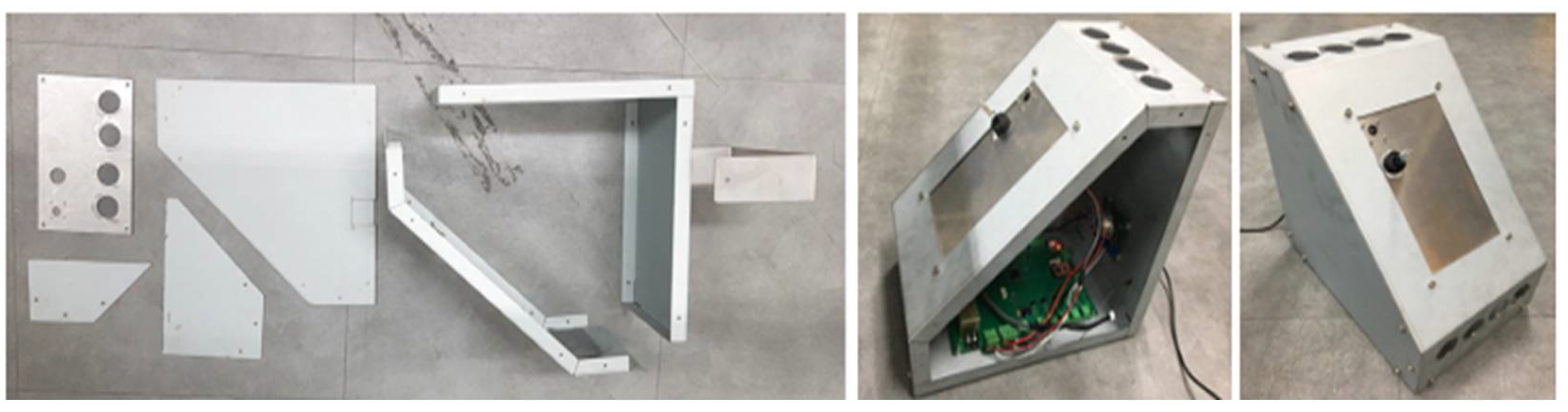
Figure 11.
Configuration example within the electric distribution panel.
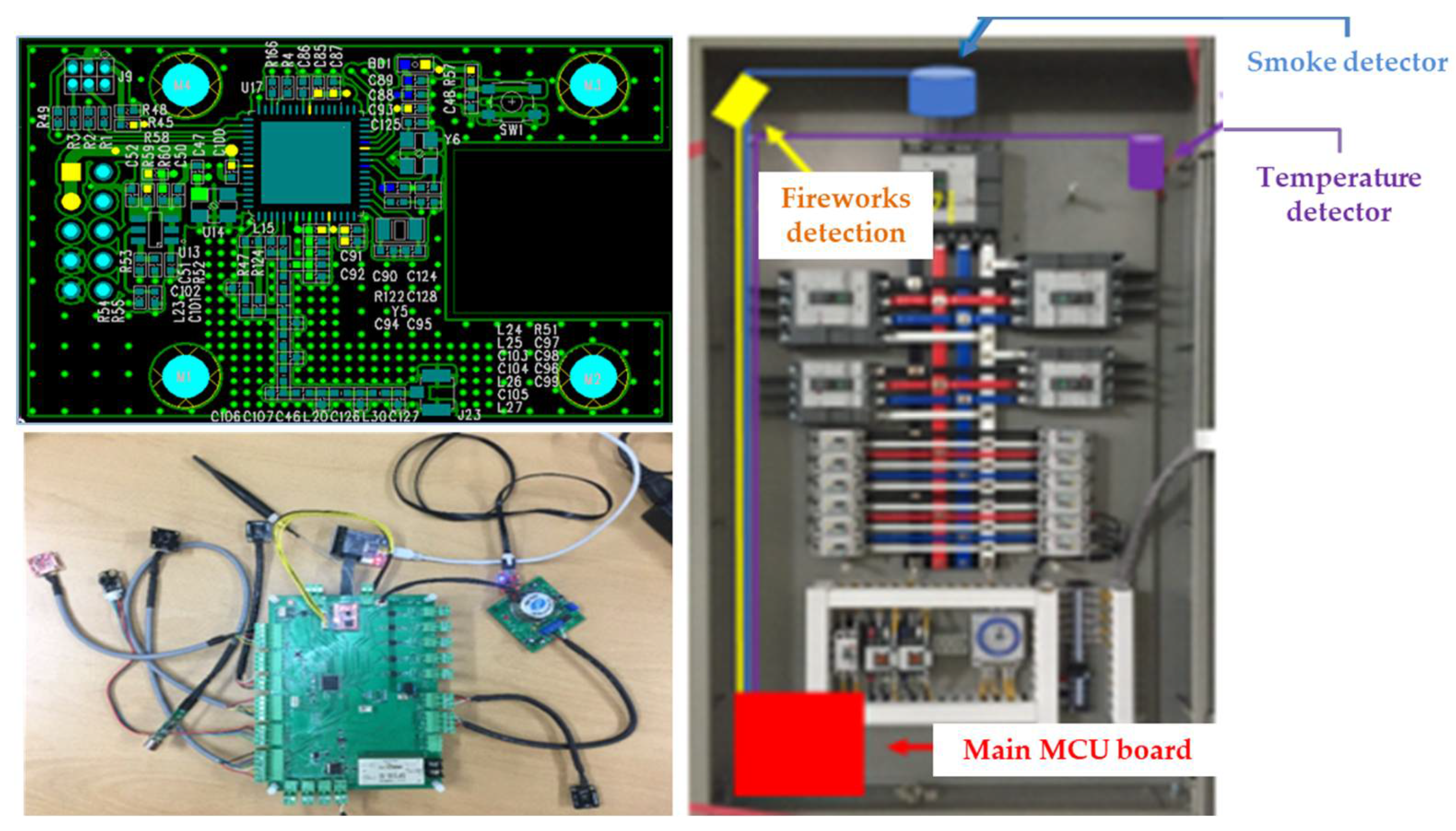
Figure 12.
Entire fire alarm network.
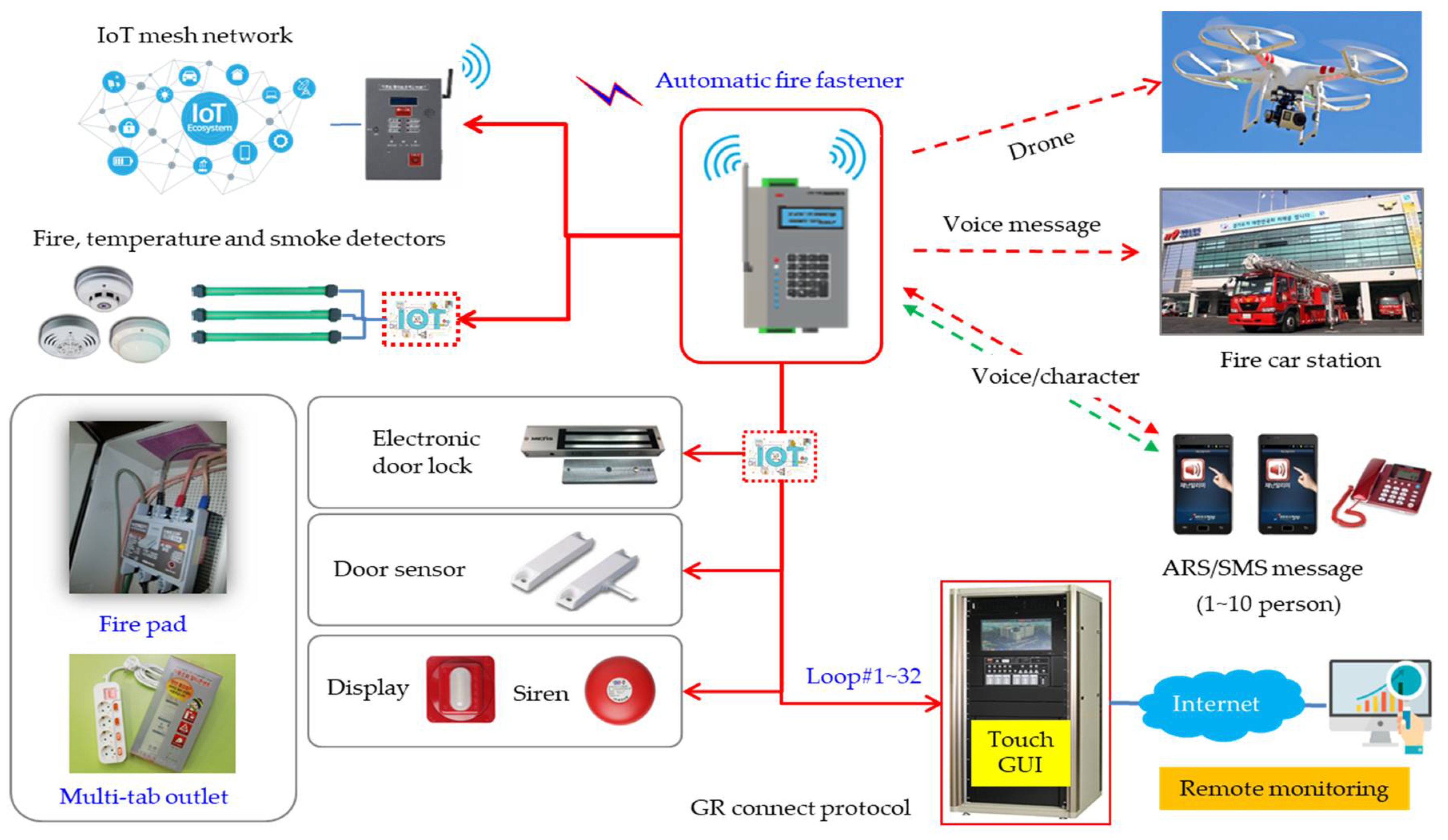
Figure 13.
Experiment to measure the air temperature inside the switchboard using a hot air fan.
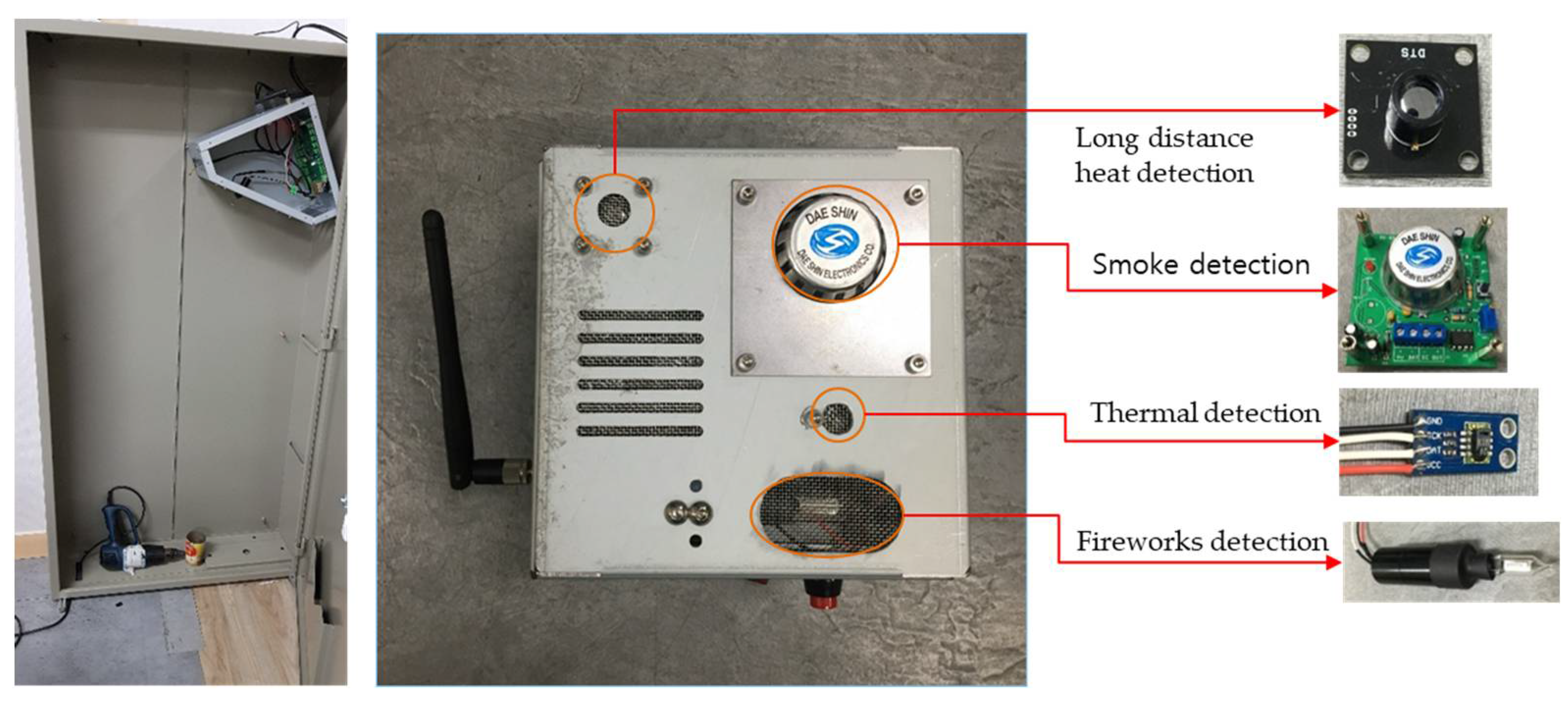
Figure 14.
Temperature and smoke concentration changes.
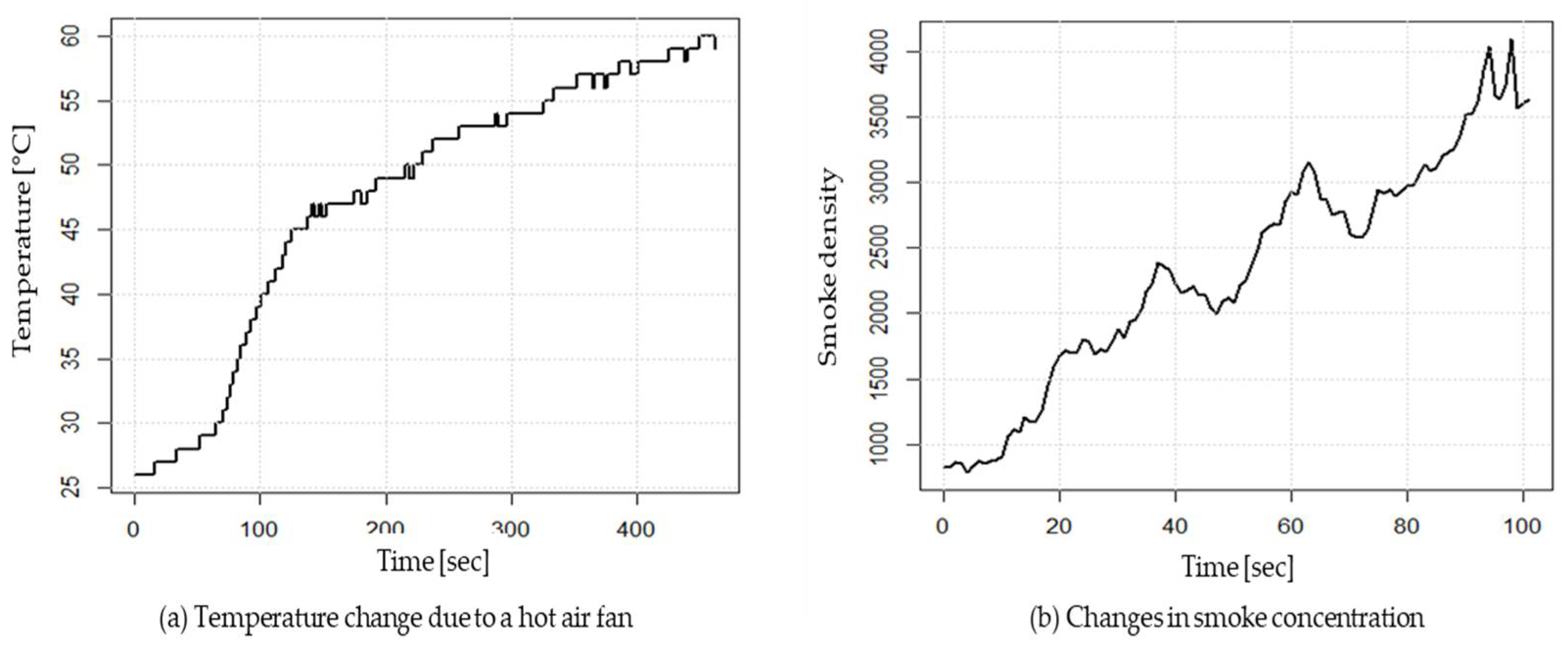
Figure 15.
Models a rectangular parallelepiped-shaped distribution panel case.
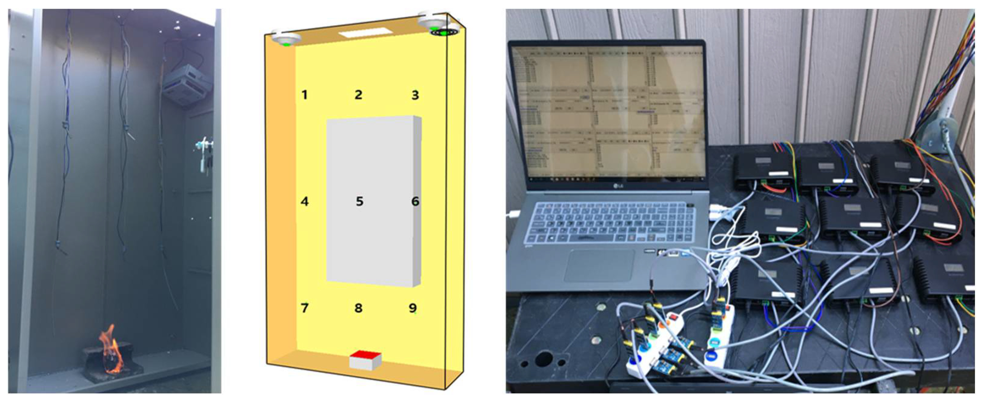
Figure 16.
Temperature change of the sensor for each position.
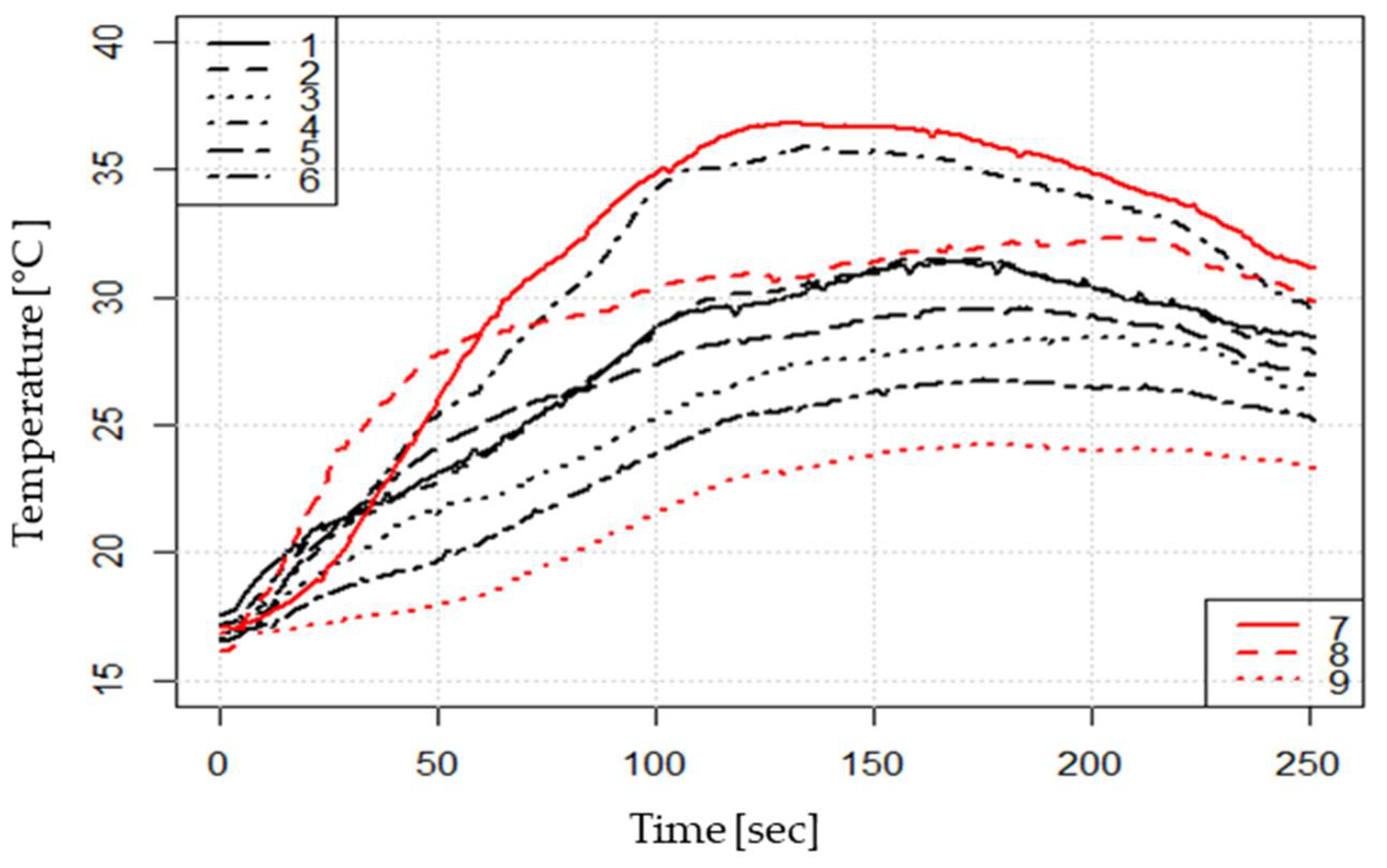
Figure 17.
Smoke density and fireworks detection changes.
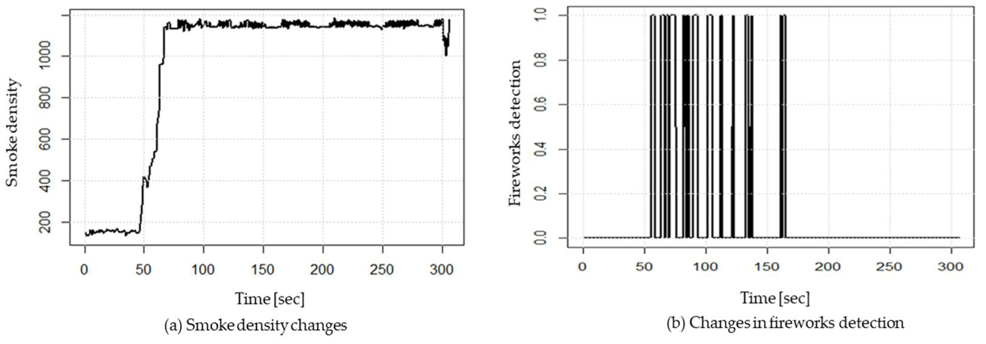
Figure 18.
Develops an app for sensors and IoT control.
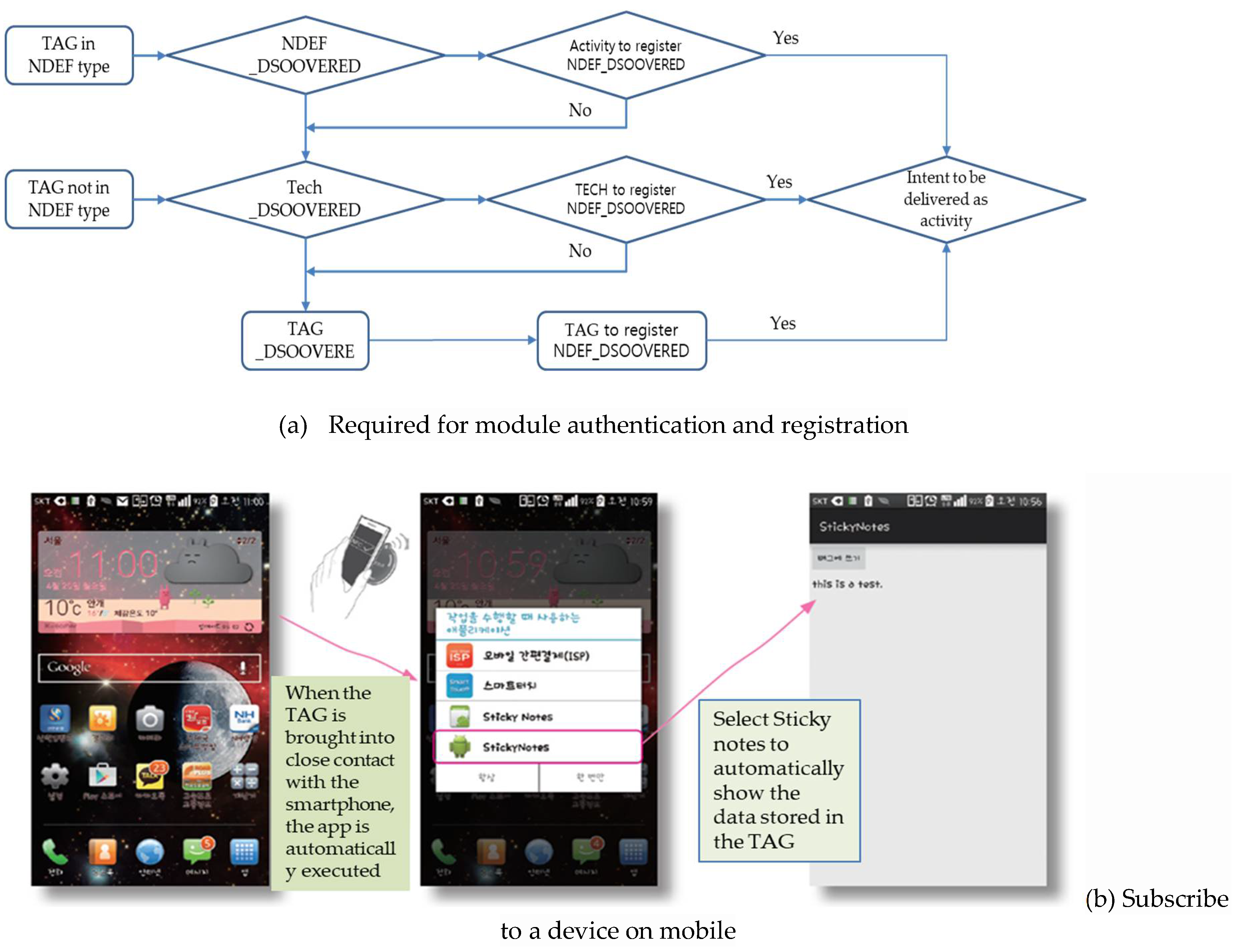
Figure 19.
Chamber test of antenna frequencies allocated for fire fighting and a case.
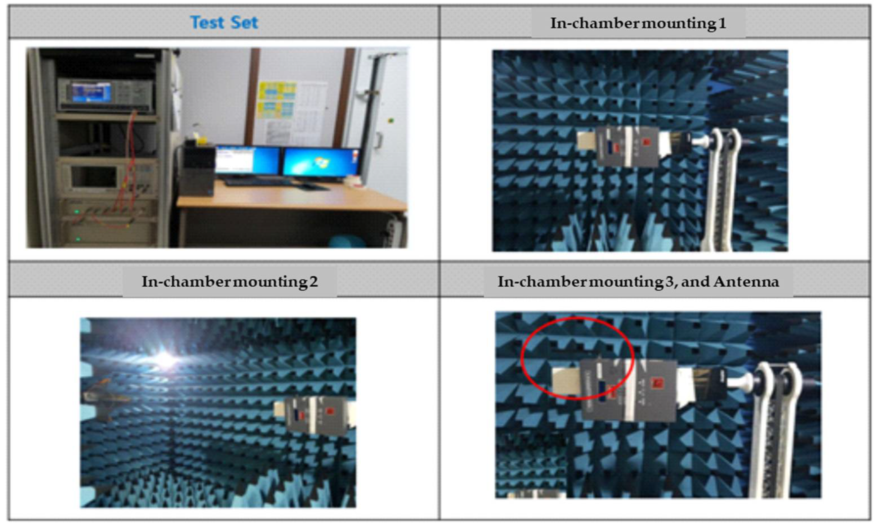
Figure 20.
Test that informs the mobile of fire information

Table 1.
Material specifications constituting the microcapsule.
| Sortation | Pad | Cord | Tube |
| Material quantity | 2.5 ~ 40 g | 25 g | 10 g |
| Protective volume | 3~60 liter | 150 liter | 2,000 liter |
| Storage temperature | - 50 ~ 80 | ||
| Activation temperature | 120 | 180 | 120 |
Table 2.
Results of the malfunction test of the temperature sensor and the smoke sensor.
| Test items | Test results | Performance requirements | ||
| Fire detection capability (Sensitivity test) |
Temperature | Operation test | 3 Sec | Operation within 34 seconds |
| Nonoperatopn test | Inoperative within 10 minutes | Inoperative within 10 minutes | ||
| Smoke | Operation test | 9 Sec | Operation within 30 seconds | |
| Nonoperatopn test | Inoperative within 5 minutes | Inoperative within 5 minutes | ||
| Notice time | Temperature | 3 Sec | Notification within 20 seconds | |
| Smoke | 9 Sec | |||
Table 3.
Specifications of 447Mhz_Sub-G Module development.
| Items | Design specification | Remarks |
| Frequency used & Channel | 447.2625 ~ 447.5625, 25 h | |
| Physical hierarchy(FHY) | IEEE 802.15.4.4 g | |
| Modulation methods | FSK, 4FSK, MSK, OOK | |
| Chip set | Silicon, Labs, EZR32LG | 32 bit core |
| Maximin Power | 10 dBm below | |
| Maximum reception sensitivity | - 133 dBm above |
Table 4.
Electrical specifications of the product..
| Symbol | Minimum | Type | Maximum | Unit |
| VCC | 2.7 | 3.0 | 3.6 | V |
| Leakage current | 0.3 | - | 3.0 | uA |
Disclaimer/Publisher’s Note: The statements, opinions and data contained in all publications are solely those of the individual author(s) and contributor(s) and not of MDPI and/or the editor(s). MDPI and/or the editor(s) disclaim responsibility for any injury to people or property resulting from any ideas, methods, instructions or products referred to in the content. |
© 2024 by the authors. Licensee MDPI, Basel, Switzerland. This article is an open access article distributed under the terms and conditions of the Creative Commons Attribution (CC BY) license (http://creativecommons.org/licenses/by/4.0/).
Copyright: This open access article is published under a Creative Commons CC BY 4.0 license, which permit the free download, distribution, and reuse, provided that the author and preprint are cited in any reuse.


