Submitted:
09 May 2024
Posted:
09 May 2024
You are already at the latest version
Abstract
This literature review offers a comprehensive analysis of antenna designs tailored for 6G applications and THz communications. Various antenna types, including elliptical lens, WHEMS, grid array, CP horn, Quasi Yagi-Uda, patch, transmit array, Vivaldi patch, SRR slotted waveguide array, RCA, and Cassegrain antennas, are scrutinized in terms of their dimensions, characteristics, frequency ranges, and materials. The study highlights existing works on antenna design for 6G applications, exploring different fabrication techniques like PCB technology, LCP technology, Topas fabrication, Wire-cutting EDM, 3D Printing, Laser-drilling processes, and CNC machining. Notably, PCB technology exhibited promise with antennas such as WHEMS, patch, and Vivaldi patch, achieving significant bandwidth and gain. However, gaps remain in research, urging further exploration into additional fabrication methods and antenna designs to meet the demands of 6G networks. The study underlines the need for advanced, intelligent antennas capable of higher bandwidth and better performance in view of future wireless communications technologies such as 6G.
Keywords:
6G antenna
; antenna design
; THz communications
; fabrication technology
1. Introduction
In addition to the possibilities provided by 5G, 6G technology is predicted to transform the world's tech environment in a major way. 6G intends to provide intelligent, deep, holographic, and omnipresent connectivity, thereby considerably expanding the breadth and depth of digital communications [1]. The 6G Network Operation Support System (OSS) will be critical for enabling advanced features such as high-level network automation, the use of intelligence across systems, and the use of digital twins to mirror physical assets in a digital form, allowing for seamless interaction between intelligent agents [2]. To increase the utility of 6G, the technology will include advanced positioning and sensing capabilities that are expected to improve communication performance and address broader goals such as sustainability, inclusiveness, and trustworthiness in technological advancements [3].
Antennas are expected to play a critical role in the deployment and success of 6G systems, meeting the demand for high-performance and aesthetically beautiful designs appropriate for modern locations. Developments in antenna technology are critical for improving beamforming capabilities, which enhance signal precision and efficiency, and strengthening security measures to protect against more complex cyber threats [4,5].
This transition needs the development of novel antenna systems capable of working efficiently at higher frequencies. Such advancements are critical for improving the performance of wireless communication systems and enabling a wide range of new applications, ranging from ultra-fast internet services to next-generation wireless communication technologies that potentially transform industries such as healthcare and transportation [6,7]. The development and execution of these sophisticated antennas is thus a critical component in the foundation of future communications in the 6G era.
Purpose And Objectives of the Literature Review
The purpose of conducting a literature review on Antenna Design for 6G Applications is to comprehensively survey and analyze the existing body of knowledge in this specific area. It aims to:
- Identify and examine the existing body of work on antenna design for 6G applications.
- Examine the problems and opportunities given by 6G's transition to higher frequencies, including the design, construction, and measurement of THz-band antennas.
- Highlight the advancements and efforts put forward by researchers in addressing the challenges of antenna design for the emerging technologies of the 5G and 6G eras.
The objectives of this literature review are manifold. It aims to update researchers, engineers, and industry professionals on the most recent discoveries and trends in antenna design for 6G applications. It is also intended to highlight the gaps in research on antenna designs for 6G networks that are not covered by the research body. Lastly, the review of literature will help people who work in this field to gain insight and ideas for future research and progress.
2. Methodology
2.1. Inclusion and Exclusion Criteria
The primary criterion for material selection is subject relevance, emphasizing research investigating antenna design approaches and fabrication technologies for 6G applications. This criterion assures that the chosen literature is relevant to the study goal and contributes to our understanding of advanced antenna design approaches for 6G applications.
Respectable publication platforms, such as IEEE Xplore, Google Scholar, ScienceDirect, SpringerLink, Wiley Online Library, IET Digital Library, Foundations and Trends in Machine Learning, and MDPI, are prioritized during the selection process to ensure the accuracy and reliability of the data collected.
Temporal considerations are also important, with a preference for papers within the last eight years that reflect the most recent innovations and breakthroughs in antenna design technology for 6G applications. This guarantees that the literature evaluation is current and appropriately reflects the status of research on this fast-growing topic.
However, studies, publications, and papers not directly linked to antenna design for 6G applications are removed. This covers research into earlier generations (such as 4G or 5G), other antennas that do not apply to 6G and other features of 6G that do not include antenna design. Publications from platforms that lack solid peer-review processes or have a reputation for providing incorrect information are also prohibited. Only older articles that reflect the most recent state of antenna design for 6G applications are included if they contain valuable historical or foundational knowledge. This guarantees that the literature review is accurate and reliable.
2.2. Literature Search Strategy and Databases Used
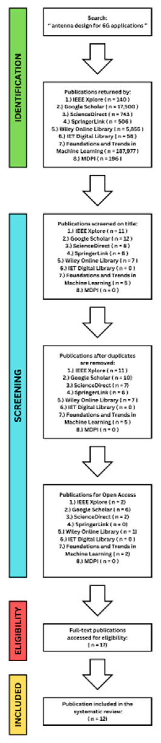
In April 2024, an elaborate inquiry with the primary objective of exploring next-generation antenna designs, specifically focusing on antenna design for 6G applications. The study began with the phrase "antenna design for 6G applications." Figure 1 depicts the strategy and results, indicating the systematic advancement of the search process.
The search produced many results from several databases, demonstrating the breadth of knowledge on the subject. The IEEE Xplore website yielded 140 results; Google Scholar 17,500, ScienceDirect 743, SpringerLink 506; Wiley Online Library 5,855; IET Digital Library 56, Foundations and Trends in Machine Learning an impressive 187,977; and MDPI 196.
A second step was taken to refine the search and focus on open-access publications, yielding a more targeted collection of results. When the search was limited to open-access papers, the number of results became more manageable. The IEEE Xplore website had two open-access results. In contrast, Google Scholar had 6, ScienceDirect had 2, SpringerLink had 0, Wiley Online Library had 1, IET Digital Library had 0, Foundations and Trends in Machine Learning had 2, and MDPI had 0.
2.3. Criteria For Selecting Relevant Studies
The initial stage of the screening procedure was a thorough review of the publishing titles. The inclusion criteria revolved around two main elements:
- 1)
- A clear link to the overarching topic of "6G technology", and
- 2)
- A clear indication in the title that the publication addressed the topic of "antenna design for 6G applications”
Then, more in-depth research was undertaken on a subset of search sites from various platforms, including IEEE Xplore, Google Scholar, ScienceDirect, SpringerLink, Wiley Online Library, IET Digital Library, Foundations and Trends in Machine Learning, and MDPI. We found and saved several relevant articles across multiple platforms using this method. However, numerous publications on these platforms still needed to fulfill our selection criteria (see Figure 1).
After combining publications from these sources, duplicate records were removed to ensure the dataset's integrity. Afterward, the full-text papers were rigorously examined using three inclusion criteria:
- 1)
- The publication was written in English
- 2)
- It discussed “antenna design techniques”
- 3)
- It focused on the “quality aspects of developing antennas for 6G applications”
The systematic literature review only included studies that met these criteria; papers that did not match these criteria were excluded. This strategy ensures thorough and high-quality coverage of this specialist issue, corresponds with the research goal and contributes substantially to our understanding of advanced antenna design techniques for 6G applications. It also helps to ensure the correctness and dependability of the data collected.
2.4. Data Extraction Process
In conducting this systematic literature review on antenna design for 6G applications, special attention was paid to four essential aspects that guarantee a comprehensive analysis of relevant data. The primary areas of focus for data extraction were:
- 1)
- The antenna design methodology,
- 2)
- Features of antenna design,
- 3)
- Information about the real-world applications used in the study,
- 4)
- Resulting measurements such as bandwidth and gain
A rigorous technique was used to collect valuable information from each publication, including essential details such as:
- The names of the participating authors
- The year of publication
- The specific antenna design method(s) used.
- Details on the real-world applications used as a reference,
3. Results and Discussion
The review section focuses on the performance and research directions on the most recent works and studies of the THz band antenna for matching the antenna specifications in the 6G wireless communication system. This section comprises 5 subsections. Subsection III-A provides an overview on the search results for the publication selection process. Subsection III-B discusses the different types of antennas. Subsection III-C presents a detailed analysis on the different antenna designs per publication. Subsection III-D shows the fabrication technologies used in the antenna designs. Lastly, Subsection III-E establishes the measurement results of each antenna design, regarding the design’s bandwidth, gain, return loss, and other parameters.
3.1. Search Results
After the removal of duplicates and unrelated publications, a total of 17 publications (i.e., n=17) from eight sources (i.e., IEEE, Google Scholar, ScienceDirect, SpringerLink, Wiley Online Library, IET Digital Library, Foundations and Trends in Machine Learning, and MDPI) as the candidates for the literature review. Following full-text publications screening and assessing the publications’ eligibility on the overall criteria of the paper, 12 publications (i.e., n=12) have met the inclusion criteria. The publication selection process is shown in Figure 1.
3.2. Antenna Type
Qadir Khan et al. conducted a recent literature review on the various types of antennas with respect to their applications [8]. In their paper, antenna types were divided into six types, namely, Wire Antenna, Travelling Wave Antenna, Reflector Antenna, Microstrip Antennas, Log Periodic Antennas, and Aperture Antenna. Other types of antennas included Wearable Antennas, M-slot Folded Antenna, and H.U.E. Slotted Microstrip Antenna.
Under the Wire Antennas, it was furtherly divided into six classes, Biconical Dipole Antenna, Left-Handed Dipole Antenna, Folded Dipole Antenna, λ/2 Folded Dipole Antenna, Half-Wave Dipole Antenna, and L-loop Antenna. Reflector Antennas were also classified into four, Helical Antenna, Yagi-uda Antenna, Spiral Antenna, and Beverage Antenna. Reflector Antennas also were classified into two, the Corner Reflector Antenna and the Parabolic Reflector (Dish Antenna). Microstrip Antennas has a specific class called the Planer Inverted-f Antenna. Moreover, Log Periodic Antennas were divided into four, Bow Tie Antennas, Log Periodic Antenna, Log Periodic Dipole Array Antenna, and Log Periodic Fractal Koch Antenna. Lastly, Aperture Antennas were classified into three, the Inverted-f Antenna, Horn Antenna, and Vivaldi Antenna.
Through these classifications and types of antennas, this literature review will be carried out efficiently since antenna types will be effectively classified and thoroughly studied, along with its frequency range, material used, fabrication technologies and its bandwidth and gain results.
3.3. Antenna Design
The papers that were included in this review mainly focuses on the various antenna designs that are suitable for 6G Applications. In order to achieve high performance metrics, an antenna design with a broadband G-band lens integrated with a dielectric grid polarizer has been developed in Reference [9]. The design was intended to achieve a full wave simulated aperture efficiency of more than 75% and an axial ratio of less than 3dB over the relative bandwidth of 35%. The primary objective of the paper was to optimize the feed-polarizer-lens system efficiently using a quasi-analytical model based on a multi-layer Spectral Green’s Function (SGF) approach. In order to analyze the lens, the study used a quasi-analytical approach to estimate the circular polarized (CP) aperture efficiency and the axial ratio of the lens after implantation. The frequency range of the antenna was limited to 180 GHz. The polarizer was manufactured with a dielectric constant of in the form of Topas material, chosen for its hardness, which facilitates the milling process. An HDPE (High-Density Polyethylene) lens was placed on top of the polarizer due to its extremely low loss properties () [10].
Reference [11] introduces a PCB-based antenna design featuring a grounded, wideband, high-efficiency electromagnetic structure (WHEMS) with a backing cavity and a radiating choke. As shown in previous researches, this antenna configuration is widely used for low frequencies applications because of its balance structure, large bandwidth and great gain characteristics [12,13,14], [15]. The antenna is constructed on two layers of printed circuit board, according to this design. The metal wall (MW) of the antenna can be constructed using either grounded vias (GV) or connected grounded vias (CGV). The substrates S1 and S2 have thicknesses of 0.765 mm and 0.508 mm, respectively, and are realized using Rogers 3003 material with a dielectric constant of 3.0.
Reference [16] focuses on creating an antenna on liquid crystal polymer (LCP) and design it for the D-band antenna-in-package applications. They have chosen to use LCP technology for the purpose of creating an antenna that provides stable performance, low material costs and large processing area. But its low laminating temperature, as well as its inherent softness, are drawbacks of the LCP. This means that in order to form a bond, the LCP needs relatively little heat and may have some limitations where it is necessary to use warmer temperatures. The paper reports that Saiz et al. have used an LCP material, which has been reported not to be able to maximize the increase in gain due to the length of the LCP rod [17]. Therefore, it is necessary to take into account the heat stability of a LCP device is due to its effect being based on an environment temperature, as this material is cost efficient and offers large processing areas.
A circularly polarized conical horn antenna operating at 0.3 THz (300 GHz) for 6G wireless applications was proposed in Reference [18] The study utilized Wire Electrical Discharge Machining (EDM). The antenna structure is composed of a waveguide feed, circular polarizer disk, and a conical horn. The proposed antenna structure consists of waveguide feed, circular polarizer disk, and a conical horn. The circular polarizer disk is crossed-slot antenna with unequal sub-wavelength lengths of Ls1 = 0.51 mm, Ls2 = 0.46 mm, and a width of Ws = 0.1 mm, with a thickness of 0.1 mm. The dimensions of for the radius of horn throat is ai = 0.4 mm, the radius of horn aperture a0 = 1.9 mm, and the conical horn axial length L = 4 mm.
A study was conducted in reference [19] on a lens antenna that is circularly polarized (CP) and has high-gain. The antenna is fed by a pyramidal horn that is linearly polarized (LP) and operates at 0.3 THz. The paper chose a lens antenna due to its high-gain applications in the THz range. This design has the advantage of avoiding the high loss of the feeding network in fed arrays due to its space feeding nature. The frequency range of operation for this design is between 0.24-0.32 THz.
A novel substrate integrated waveguide (SIW) Quasi Yagi-Uda antenna was suggested in the reference [20] to demonstrate the impact of PBG and SIW formation on the gain and Q-factor of this antenna type. These parameters are crucial in various applications related to 6G satellite communication. The research also analyzed the influence of the graphene layer on the return loss of the transmission line.
An antenna design was proposed in reference [21] that utilized a 16-element antenna array along with a wide-band cavity-backed aperture-coupled patch antenna. The aim of this design was to target D-band applications. In this study, the transmission lines used to investigate the possible losses at the D-band were microstrip line and grounded coplanar waveguide (GCPW). The antenna array was intended to operate within a frequency range of 135-155 GHz or 0.135-0.155 THz. The final PCB used in this design had a total thickness of 373µm, which included the plated copper layers. The substrate material chosen for this design was Megtron 7N (εr = 3.20, tan δ = 0.003 at 50 GHz) produced by Panasonic, which was selected for its dielectric properties, dielectric thickness availability, and ease of processing. For patterning the PCB, traditional methods were used along with photolithography to determine the areas where the copper should be retained, whereas those that are unimaged will be etched away [22]. A parametric analysis of the proposed patch antenna was performed by changing the main design parameters lp & wp, lap, and lst
Following this, reference [23] proposed an all-dielectric Huygens’ transmit array which was demonstrated in the 120 GHz band. In order to quantify the effect on antenna gain and estimate the tolerance of a uniform array, this paper has used laser drilling technology. This paper also presented a brief comparison of the related antenna design.
In reference [24], the design and analysis of Vivaldi antennas for millimeter and terahertz (THz) band applications were presented. The antennas were tested within the frequency range of 0.06125 THz to 0.06215 THz. The study involved optimizing dimensions, including parameters such as ANT-1 (µm), ANT-2 (µm), ANT-3 (mm), ANT-4 (mm), ANT-1 (µm²), ANT-2 (µm²), ANT-3 (mm²), and ANT-4 (mm²), for different aspects of the proposed Vivaldi antennas. Furthermore, the paper conducted analyses of four different Vivaldi antenna structures within the frequency range of 0.06 THz to 0.065 THz, as well as in the millimeter-wave frequency band ranging from 0.56 THz to 0.74 THz.
In reference [25], an antenna design featuring a split ring resonators (SRR) slotted waveguide array was proposed. This antenna demonstrated a 10 dB impedance bandwidth spanning 88 GHz, ranging from 0.244 THz to 0.332 THz. Additionally, an axial ratio bandwidth of 35.71 GHz, covering frequencies from 0.25172 THz to 0.28751 THz, was achieved. The study included investigations into parametric variations of slot width and split gap, analyzing their effects on return loss and gain characteristics of the antenna. This research highlights the importance of optimizing slot geometry and split configurations to achieve desired performance metrics in terms of impedance bandwidth and axial ratio over a wide frequency range in the terahertz spectrum.
The referenced paper [26] provides a comprehensive review of antennas showcasing advancements in wideband and high-gain sub-millimeter wave and low-THz frequencies. It presents a comparative analysis of the performance of these antennas. Additionally, the paper explores an all-metal model inspired by Fabry-Perot cavity (FPC) theory and its application in THz communications. A notable contribution of the study is the development of a wideband, high-gain resonant cavity antenna (RCA) designed to operate at 300 GHz. Despite being fabricated at a size ten times larger than the operational frequency (30 GHz), the antenna was successfully produced using metal binder jetting technology, a form of 3D printing.
Lastly, Reference [27] design a Sub-THz offset Cassegrain antenna for multi-Gbps applications. The antenna was demonstrated within the frequency range of 0.22-0.3 THz (220-300 GHz). The primary objective of the study was to assess the feasibility of employing an offset dual-reflector configuration to achieve high gain and wideband characteristics for sub-THz point-to-point radio communication. The antenna design featured a conical horn feed combined with a rectangular waveguide section incorporating a smooth E-plane bend of 35.6°. The antenna was configured for linear (vertical) polarization. Additionally, the weight of the antenna was specified at 640 grams.

Table 1.
shows the 12 publications reviewed in this paper where the antenna types, frequency range, material used for the antenna design, its fabrication technology, and its results were summarized.
Table 1.
shows the 12 publications reviewed in this paper where the antenna types, frequency range, material used for the antenna design, its fabrication technology, and its results were summarized.
| Reference No. | Antenna Type | Frequency Range | Material | Fabrication Technology | Results | |
|---|---|---|---|---|---|---|
| Bandwidth | Gain | |||||
| [9] | Circularly Polarized Antenna | 180 GHz | Topas material | Topas Fabrication | Not indicated | 34 dB |
| [11] | WHEMS a | 0.06-0.075 THz | Rogers 3003 | PCB b technology | 11 GHz | 8-10 dBi |
| [16] | Grid Array Antenna | 0.136-0.157 THz | Compensated by 0.5 mm copper core | LCP c Technology | 21 GHz | 14.5 dBi |
| [18] | Circularly Polarized Conical Horn Antenna | 0.27-0.33 THz | Brass block | Wire-cutting EDM d | 60 GHz | 18.3 dBic |
| [19] | Circularly Polarized Lens antenna | 0.24-0.32 THz | High-temperature resin | 3D Printing | 80 GHz | 30.8 dBic |
| [20] | Quasi Yagi-Uda antenna | 0.455-0.53 THz | Graphene loads | CMOS e technology and TSV f fabrication process | 75 GHz | 9 dB |
| [21] | Patch Antenna and Antenna Array | 0.135-0.155 THz | Megtron 7N substrate | PCB technology | 20 GHz | 14 dBi |
| [23] | Transmit array | 0.12-0.13 THz | All-dielectric structure | Laser-drilling | 10 GHz | 32-34 dB |
| [24] | Vivaldi patch antenna | 0.06125-0.06215 THz | Metallic on Rogers RT5880 Substrate | PCB technology | 180 GHz | 11.77 dB peak gain, 11.89 dBi |
| [25] | SRR g Slotted Waveguide Array | 0.244-0.332 THz | Metallic waveguide | Not indicated | 88 GHz | 15.2 dBi |
| [26] | Resonant Cavity Antenna | 0.0265-0.04 THz | Metal | 3D printing | 13.5 GHz | 13–16 dBi |
| [27] | Offset Cassegrain antenna | 0.22-0.31 THz | Brass but gold plated | CNC h machining technology | 80 GHz | 48 dBi max gain |
WHEMS: Wideband, High-Efficiency Electromagnetic Structure. bPCB: Printed Circuit Board. cLCP: Liquid Crystalline Polymer. dEDM: Electric Discharge Machining. eCMOS: Complementary Metal-Oxide Semiconductor. fTSV: Through-Silicon Via.gSRR: Split Ring Resonators.hCNC: Computer Numerical Control
3.4. Fabrication Technology
LCP Technology: Authors in reference [16] discussed LCP (Liquid Crystal Polymer) technology, highlighting its advantages such as low material cost and compatibility with low-cost processes like wet etching. Ji et al. described LCP as an organic thermoplastic with high temperature resistance, low moisture absorption, and good mechanical properties, making it ideal for fabrication of millimeter-wave devices [28]. Similarly, studies focusing on LCP technologies for terahertz (THz) applications emphasized its characteristics including high flame resistance, dielectric stability, mechanical strength, and compatibility with standard photolithography when laminated with copper claddings [29]. LCP is considered more suitable for THz applications compared to silica glass and PTFE (Polytetrafluoroethylene), which can be challenging to process [30]. Due to its capabilities in multi-layer organic processing, LCP has emerged as a promising material for RF (Radio Frequency) and THz applications, offering advantages in terms of fabrication flexibility and performance characteristics.
PCB Technology: Authors in references [11,21], and [24] discussed the utilization of PCB (Printed Circuit Board) fabrication technology in their studies. Printed circuit board technology has been used to establish electrical connections through surface metal etch and plating vias, as referred to in reference [11]. The study focused on constructing a two-layer PCB with metal walls using grounded vias (GV) and connected grounded vias (CGV) for enhanced performance. In reference [21], the PCB technology has been specifically applied to D-band applications using the semi additive processing of conductors multilayered on a substrate. This method has allowed the creation of antennas suitable for HF applications. Similarly, in reference [24], traditional PCB etching procedures were used to fabricate tested antennas. New research has brought attention to the positive results of PCB production techniques for 6G communications and terahertz (THz) applications. This was made evident in recent studies, as cited in references [31] and [32].
Topas Fabrication: The main process involved in manufacturing HDPE (High-Density Polyethylene) is producing the HDPE material itself. This material is commonly utilized for applications like antenna enclosures and support structures [33,34,35]. Authors by [9] made a polarizer from Topas material which was fabricated, with an HDPE lens incorporated on top of it.
CNC (Computer Numerical Control) Machining: The authors used CNC Computer Numerical Control machining to precisely design the paraboloidal profile of the top reflector and the convex hyperboloid profile of the subreflector, according to reference [27]. CNC machining, known for its accuracy in making complex shapes and profiles, is a flexible method that can be used. Studies investigating the effects of surface roughness from various fabrication technologies, including CNC machining, have shown that nano CNC machining offers superior performance with minimal loss [36]. Additionally, research has highlighted CNC machining as an energy-efficient and cost-effective fabrication method [37].
3D Printing Technology: The authors of references [19] and [26] both utilized 3D printing fabrication technology in their studies. In [19], 3D printing was employed to create the circularly polarized (CP) lens using a process that utilizes a laser to solidify isotropic parts from liquid photopolymer resin. In [26], 3D printing, along with additive manufacturing (AM), was utilized to manufacture the complex antenna structure of the study, ensuring high precision at a low cost. This approach highlights the versatility and effectiveness of 3D printing technology in antenna fabrication. Several other studies have also adopted 3D printing technology for antenna fabrication, as evidenced by references [38,39,40], [41].
Wire Cutting EDM: The electric discharge machining (EDM) process is a non-traditional thermal-based machining technique commonly employed for machining hard materials like ceramics and superalloys [42]. Authors in [18] used Wire-cutting EDM fabrication technology to create a compact and highly efficient circularly polarized conical horn antenna.
Laser-drilling: Authors in [23] used a laser drilling fabrication technology to realize bridge-connected dielectric resonators. This approach enabled accurate prototyping of small resonator dimensions without mechanical vibrations, resulting in very low fabrication tolerances. Similarly, several 6G (sixth-generation) applications have utilized laser-drilling processes to facilitate more cost-effective manufacturing techniques, as highlighted in previous studies [43,44,45] [46]. This indicates the growing trend of leveraging laser drilling for precision manufacturing in high-frequency and advanced wireless communication applications.
CMOS technology: In reference [20], the proposed antenna was fabricated using CMOS (Complementary Metal-Oxide-Semiconductor) technology and TSV (Through-Silicon Via) processes. These fabrication techniques were utilized for defining and creating the diameter and pitch of the cylindrical part of the antenna. Similar fabrication technology has been employed in recent studies, such as the design of a miniaturized substrate integrated waveguide bandpass filter for THz applications [47]. Recent research highlights the viability of CMOS technology and TSV fabrication for applications involving millimeter-wave (mm-wave) and terahertz (THz) integrated circuits [48]. This underscores the growing importance and potential of these fabrication methods in advancing technologies for high-frequency applications.
3.5. Measurement and Results
Reference [9] obtained a full-wave simulated aperture efficiency higher than 75% and a relative bandwidth of over 44% relative bandwidth, and an axial ratio lower than 3 dB with over 35% relative bandwidth. The circularly polarized lens reached more than 30 dB of gain with only 0.65 dB dielectric loss. The measured resulting gain of the design is 34 dB while its total bandwidth was not indicated. These results illustrate the antenna's capability to generate multiple directives circularly polarized beams while effectively maintaining the axial ratio bandwidth.
Reference [11], an antenna achieved a gain bandwidth of 22%, corresponding to 0.011 THz (or 11 GHz), spanning from 0.06 THz to 0.075 THz. Within this frequency band, the antenna demonstrated a relative gain of 8-10 dBi. The radiation aperture used in this study was 4.7 × 4.7 mm² (equivalent to 1 × 1 elements).
In reference [16], the authors proposed an antenna with an impedance bandwidth spanning from 0.136 THz to 0.157 THz (equivalent to 136 GHz to 157 GHz). The antenna achieved a maximum gain of 14.5 dBi at 0.146 THz and exhibited vertical beams in the broadside direction within the frequency range of 0.141 THz to 0.149 THz.
In reference [18], a CP (Circularly Polarized) conical horn antenna was designed for operation in the frequency range of 0.27 THz to 0.33 THz, providing a bandwidth of 60 GHz. The antenna achieved a measured directivity of 18.3 dBic at the broadside direction specifically at 0.312 THz. The results demonstrated that the measured normalized radiation patterns closely matched the simulated results across different frequencies in both the elevation and azimuth planes, particularly at the broadside direction with good symmetry in both planes. The antenna design utilized an all-metal structure fabricated using Wire-EDM (Wire Electrical Discharge Machining) technology, showcasing high precision in the manufacturing of its components.
In reference [19], a high-gain CP (Circular Polarization) lens antenna was developed to achieve right-hand circular polarization (RHCP) radiation using an LF (Low Frequency) feed source. The antenna obtained a gain of 30.8 dBic at 0.3 THz. The measured 1-dB gain bandwidth and 3-dB axial ratio (AR) bandwidth of the THz CP lens reached 13.3% and 18.8%,
Reference [20] proposes a novel substrate integrated waveguide (SIW) Quasi Yagi–Uda antenna design with a Q-factor of 573 at 0.482 THz. To address return loss issues in harmonics and enhance the antenna bandwidth to 15.2%, a THz filter employing graphene load was introduced between the power divider and the array antenna. The suggested total gain of the antenna was 9.07 dB, featuring a directive pattern and a side-lobe level of -5 dB. The results of this design demonstrated a wider bandwidth covering 0.45 to 0.5 THz, with a gain of 9 dB.
In reference [21], the design focused on a wide-band cavity-backed aperture-coupled patch antenna and a 16-element antenna array on a multilayer printed circuit board (PCB) for D-band applications. The insertion loss was measured at 1.9 dB/cm for the microstrip line and 1.8 dB/cm for the coplanar waveguide at 0.15 THz. The study results indicated that the maximum gain for a single antenna was 7 dBi, and for the 16-element array, it was 14 dBi, both achieved at 0.143 THz. The measured antenna input matching bandwidth was 0.02 THz. The presented D-band antennas and PCB substrate technology demonstrated good performance and enabled the integration of complex MMICs (Monolithic Microwave Integrated Circuits) and antennas into scalable phased antenna arrays.
Reference [23] proposes an all-dielectric Huygens' transmit array was proposed and demonstrated in the 0.12 THz band. The results of the study revealed that the design caused a maximum decrease in gain of approximately 2 dB. The frequency range covered by this design was from 0.12 THz to 0.13 THz, achieving a gain ranging between 32 dB to 34 dB.
The Vivaldi antennas designed in reference [24] achieved a simulated gain of -10 dB and an impedance bandwidth of approximately 0.076 THz, with a minimum return loss of -58.83 dB. The peak gain reached 11.77 dB, and the Voltage Standing Wave Ratio (VSWR) was 1.002. Additionally, the radiation efficiency was measured at 97.4%, and the directivity was 11.89 dBi at a resonant frequency of 0.603 THz. To validate the design method, the antennas were tested at frequencies of 0.06125 THz and 0.06215 THz.
The antenna described in reference [25] exhibits a 10 dB impedance bandwidth spanning 0.088 THz, specifically from 0.244 THz to 0.332 THz, covering the WM864 band with a maximum gain of 15.3 dBi. This design also features a broad 3 dB axial ratio (AR) bandwidth of 0.03571 THz, ranging from 0.25172 THz to 0.28751 THz. The study's results demonstrate that this SRR (Split Ring Resonator) Slotted Waveguide Array achieved a gain of 15.2 dBi and a resulting bandwidth of 88 GHz, a 35 GHz range within the 3 dB AR bandwidth, and a radiation efficiency of 94%.
The design presented in reference [26] yielded two sets of results: one from simulation and the other from fabrication. In simulation, the antenna was modeled with a size of 2.4 × 2.4 mm, operating in the H-band, using a 3DP fabrication technique, achieving a 9.9% bandwidth for 3 dB gain, and a peak gain of 16.2 dB. Upon actual 3D printing fabrication, the antenna size increased to 24 × 24 mm, with the working band shifting to Ka-band, maintaining a 10% bandwidth for 3 dB gain, and achieving a peak gain of 16 dB.
Finally, findings in reference [27] indicated that the reflection coefficient of the Sub-THz offset Cassegrain antenna is -19 dB across a bandwidth of 0.22-0.31 THz. The antenna achieved a half-power beamwidth ranging from 0.7° to 0.8°, with the worst-case sidelobe level below -24 dB. The maximum measured gain was 48 dBi.
4. Conclusions
This literature review provided a comprehensive analysis on the antenna designs for 6G applications and THz communications. The analyzes various antenna types, such as elliptical lens antenna, WHEMS with GV and CGV walls antenna, grid array antenna, CP horn antenna, Quasi Yagi-Uda antenna, patch antenna, transmit array, Vivaldi patch antenna, SRR slotted waveguide array, RCA, and Cassegrain antenna. The review defines and compares their dimensions and characteristics, which is the main objective of the study. Additionally, it defines their frequency ranges and materials used.
The review found many existing works of literature regarding antenna designs for 6G applications, with various methods and fabrication techniques. The study determined that fabrication technologies such as PCB technology, LCP technology, Topas fabrication, Wire-cutting EDM, 3D Printing, Laser-drilling processes, and CNC machining were effective fabrication techniques for designing antennas compatible with THz communication and 6G applications. PCB technology was useful for antenna types such as wideband, high-efficiency electromagnetic structure (WHEMS) antennas, patch antennas, and Vivaldi patch antennas. LCP technology was useful for grid array antennas. Topas fabrication and wire-cutting EDM were useful for CP antennas. 3D printing was used for high-temperature resin materials on CP antennas and metal materials on resonant cavity antennas. Quasi Yagi-Uda antennas were applied with the TSV fabrication process due to their Graphene loads. Lastly, CNC machining technology was applied to offset Cassegrain antennas due to their brass material with gold plating.
Results in these publications show that the PCB fabrication technology applied to the Vivaldi patch antenna resulted in a bandwidth measurement of 180 GHz with 11.77 dB peak gain. Among the resulting measurements in the literature review, this antenna design obtained the largest bandwidth and high-gain results.
This literature review shows the current trends in the 6G networks. However, for other types of antennas, there is still a lack of work. The results of the study suggest that further investigation of other fabrication technologies and other antenna designs should be undertaken by future researchers. It is also necessary to develop intelligent and autonomous antennas with higher bandwidths, as well as high gain performance. The need for advanced technology and antenna design is urgent given the imminent arrival of 6G wireless communications.
Acknowledgment
The authors gratefully acknowledge the professors and faculty members of DCEE for evaluating and proofreading this paper.
References
- Y. Lu and X. Zheng, “6G: A survey on technologies, scenarios, challenges, and the related issues,” Journal of Industrial Information Integration, vol. 19, p. 100158, Sep. 2020. [CrossRef]
- Y. Ouyang et al., “6G Network Operation Support System,” 2023. [CrossRef]
- H. Wymeersch et al., “6G Positioning and Sensing Through the Lens of Sustainability, Inclusiveness, and Trustworthiness,” 2023. [CrossRef]
- S. Iffat Naqvi and N. Hussain, “Antennas for 5G and 6G Communications,” in 5G and 6G Enhanced Broadband Communications [Working Title], IntechOpen, 2022. [CrossRef]
- T. O. Olwal, P. N. Chuku, and A. A. Lysko, “Antenna Research Directions for 6G : A brief overview through sampling literature,” in 2021 7th International Conference on Advanced Computing and Communication Systems (ICACCS), Coimbatore, India: IEEE, Mar. 2021, pp. 1582–1587. [CrossRef]
- B. Duan, “Evolution and innovation of antenna systems for beyond 5G and 6G,” Front Inform Technol Electron Eng, vol. 21, no. 1, pp. 1–3, Jan. 2020. [CrossRef]
- Z. R. M. Hajiyat, A. Ismail, A. Sali, and Mohd. N. Hamidon, “Antenna in 6G wireless communication system: Specifications, challenges, and research directions,” Optik, vol. 231, p. 166415, Apr. 2021. [CrossRef]
- A. Q. Khan, M. Riaz, and A. Bilal, “Various Types of Antenna with Respect to their Applications: A Review,” INTERNATIONAL JOURNAL OF MULTIDISCIPLINARY SCIENCES AND ENGINEERING, vol. 7, no. 3, Mar. 2016.
- M. A. Campo, G. Carluccio, D. Blanco, O. Litschke, S. Bruni, and N. Llombart, “Wideband Circularly Polarized Antenna With In-Lens Polarizer for High-Speed Communications,” IEEE Transactions on Antennas and Propagation, vol. 69, no. 1, pp. 43–54, Jan. 2021. [CrossRef]
- M. A. Campo, G. Carluccio, D. Blanco, S. Bruni, O. Litschke, and N. Llombart, “Dielectric-Grating In-Lens Polarizer for Beyond 5G Communications,” in 2019 44th International Conference on Infrared, Millimeter, and Terahertz Waves (IRMMW-THz), Sep. 2019, pp. 1–2. [CrossRef]
- L. Chi, Z. Weng, Y. Qi, and J. L. Drewniak, “A 60 GHz PCB Wideband Antenna-in-Package for 5G/6G Applications,” IEEE Antennas and Wireless Propagation Letters, vol. 19, no. 11, pp. 1968–1972, Nov. 2020. [CrossRef]
- Z. Cai, Y. Qi, Z. Weng, W. Yu, F. Li, and J. Fan, “DC ground compact wideband omnidirectional vertically polarised slot loop antenna for 4G long-term evolution applications,” IET Microwaves, Antennas & Propagation, vol. 12, no. 7, pp. 1087–1092, 2018. [CrossRef]
- Y. Xiao, Y. Qi, F. Li, J. Fan, W. Yu, and L. Lu, “Dual-Band Directional Slot Antenna for Wi-Fi Application,” IEEE Transactions on Antennas and Propagation, vol. 66, no. 8, pp. 4277–4281, Aug. 2018. [CrossRef]
- L. Chi, Y. Qi, Z. Weng, W. Yu, and W. Zhuang, “A Compact Wideband Slot-Loop Directional Antenna for Marine Communication Applications,” IEEE Transactions on Vehicular Technology, vol. 68, no. 3, pp. 2401–2412, Mar. 2019. [CrossRef]
- L. Chi, Y. Qi, Z.-B. Weng, W. Yu, F. Li, and J. L. Drewniak, “Directional Antenna With Consistent H-Plane Dual-Band Beamwidth for Wi-Fi Applications,” IEEE Transactions on Antennas and Propagation, vol. 67, no. 7, pp. 4495–4505, Jul. 2019. [CrossRef]
- Zhang, C. Kärnfelt, H. Gulan, T. Zwick, and H. Zirath, “A D -Band Packaged Antenna on Organic Substrate With High Fault Tolerance for Mass Production,” IEEE Transactions on Components, Packaging and Manufacturing Technology, vol. 6, no. 3, pp. 359–365, Mar. 2016. [CrossRef]
- N. Saiz, N. Dolatsha, and A. Arbabian, “A 135GHz SiGe transmitter with a dielectric rod antenna-in-package for high EIRP/channel arrays,” in Proceedings of the IEEE 2014 Custom Integrated Circuits Conference, Sep. 2014, pp. 1–4. [CrossRef]
- B. Aqlan, M. Himdi, L. Le Coq, and H. Vettikalladi, “Sub-THz Circularly Polarized Horn Antenna Using Wire Electrical Discharge Machining for 6G Wireless Communications,” IEEE Access, vol. 8, pp. 117245–117252, 2020. [CrossRef]
- G. B. Wu, Y.-S. Zeng, K. F. Chan, S.-W. Qu, and C. H. Chan, “High-Gain Circularly Polarized Lens Antenna for Terahertz Applications,” IEEE Antennas and Wireless Propagation Letters, vol. 18, no. 5, pp. 921–925, May 2019. [CrossRef]
- Z. S. Tabatabaeian, “Graphene load for harmonic rejection and increasing the bandwidth in Quasi Yagi–Uda array THz antenna for the 6G wireless communication,” Optics Communications, vol. 499, p. 127272, 2021. [CrossRef]
- A. Lamminen, J. Säily, J. Ala-Laurinaho, J. de Cos, and V. Ermolov, “Patch Antenna and Antenna Array on Multilayer High-Frequency PCB for D-Band,” IEEE Open Journal of Antennas and Propagation, vol. 1, pp. 396–403, 2020. [CrossRef]
- M. Gantz, “mSAP: The new PCB manufacturing imperative for 5G smartphones,” Electronic design, Feb. 2020, [Online]. Available: https://cdn.baseplatform.io/files/base/ebm/electronicdesign/document/20.
- M. K. Emara, S. K. Stuhec-Leonard, T. Tomura, J. Hirokawa, and S. Gupta, “Laser-Drilled All-Dielectric Huygens’ Transmit-Arrays as 120 GHz Band Beamformers,” IEEE Access, vol. 8, pp. 153815–153825, 2020. [CrossRef]
- R. K. Kushwaha and P. Karuppanan, “Design and analysis of Vivaldi antenna with enhanced radiation characteristics for mm-wave and THz applications,” Optical and Quantum Electronics, vol. 51, no. 9, p. 309, Sep. 2019. [CrossRef]
- K. K. Ansha, P. Abdulla, P. M. Jasmine, and U. Sam Kollannore, “Circularly polarized split ring slotted waveguide array antenna for 6G communications,” Optik, vol. 247, p. 167920, Dec. 2021. [CrossRef]
- R. Xu et al., “A Review of Broadband Low-Cost and High-Gain Low-Terahertz Antennas for Wireless Communications Applications,” IEEE Access, vol. 8, pp. 57615–57629, 2020. [CrossRef]
- A. Kosogor and Y. Tikhov, “A 220-300 GHz Offset Dual-Reflector Antenna for Point-to-Point Radio,” in 2020 14th European Conference on Antennas and Propagation (EuCAP), Mar. 2020, pp. 1–3. [CrossRef]
- Y. Ji, Y. Bai, X. Liu, and K. Jia, “Progress of liquid crystal polyester (LCP) for 5G application,” Advanced Industrial and Engineering Polymer Research, vol. 3, no. 4, pp. 160–174, Oct. 2020. [CrossRef]
- Z. Zhou et al., “Flexible Liquid Crystal Polymer Technologies from Microwave to Terahertz Frequencies,” Molecules, vol. 27, no. 4, 2022. [CrossRef]
- K. CÜNERAY and N. AKÇAM, “LCP Substrate Based Crescent Shaped Microstrip Patch Array Antenna Design For 5G Applications,” in 2019 3rd International Symposium on Multidisciplinary Studies and Innovative Technologies (ISMSIT), Oct. 2019, pp. 1–4. [CrossRef]
- G. Buttazzoni et al., “A Beamforming Network for 5G/6G Multibeam Antennas Using the PCB Technology,” in 2023 17th European Conference on Antennas and Propagation (EuCAP), Mar. 2023, pp. 1–5. [CrossRef]
- T. Dao, A. Kearns, D. Reyes Paredes, and G. Hueber, “Wideband High-Gain Stacked Patch Antenna Array on Standard PCB for D-Band 6G Communications,” IEEE Antennas and Wireless Propagation Letters, vol. 23, no. 2, pp. 478–482, Feb. 2024. [CrossRef]
- A.V. Shevchik-Shekera, F. F. Sizov, O. G. Golenkov, I. O. Lysiuk, V. O. Petriakov, and M. Yu. Kovbasa, “Silicon lenses with HDPE anti-reflection coatings for low THz frequency range,” Semiconductor Physics, Quantum Electronics & Optoelectronics, pp. 059–067. [CrossRef]
- Y. S. Lee et al., “Low-Loss Polytetrafluoroethylene Hexagonal Porous Fiber for Terahertz Pulse Transmission in the 6G Mobile Communication Window,” IEEE Transactions on Microwave Theory and Techniques, vol. 69, no. 11, pp. 4623–4630, Nov. 2021. [CrossRef]
- M. H. K. Anik et al., “Numerical Design and Investigation of Circularly Segmented Air Holes-Assisted Hollow-Core Terahertz Waveguide as Optical Chemical Sensor,” IEEE Access, vol. 9, pp. 86155–86165, 2021. [CrossRef]
- D. O. Kim, S. M. Oh, J. Y. Lee, and D. H. Cho, “Surface Roughness Effects of Fabrication Technology on Metallic Waveguide in D-Band for 6G RF Communications,” in 2023 Photonics & Electromagnetics Research Symposium (PIERS), Jul. 2023, pp. 2205–2208. [CrossRef]
- Y. Xiao, Z. Jiang, Q. Gu, W. Yan, and R. Wang, “A novel approach to CNC machining center processing parameters optimization considering energy-saving and low-cost,” Journal of Manufacturing Systems, vol. 59, pp. 535–548, Apr. 2021. [CrossRef]
- J. A. P. Ribeiro, E. C. V. Boas, F. A. P. Figueiredo, and J. R. Mejía-Salazar, “Photonics-based all-dielectric horn antenna for millimeter waves in 5G and 6G applications,” Applied Physics Letters, vol. 124, no. 4, p. 043501, Jan. 2024. [CrossRef]
- J. C. Zhang et al., “A 6G meta-device for 3D varifocal,” Science Advances, vol. 9, no. 4, p. eadf8478, 2023. [CrossRef]
- J. Shi et al., “Artificial intelligence-assisted accurate spectrum prediction in design of terahertz fiber operating in 6G communication window,” IEEE Journal of Selected Topics in Quantum Electronics, pp. 1–9, 2023. [CrossRef]
- N. Chudpooti, N. Duangrit, S. Chudpooti, P. Akkaraekthalin, I. D. Robertson, and N. Somjit, “THz Photo-Polymeric Lens Antennas for Potential 6G Beamsteering Frontend,” in 2021 International Symposium on Antennas and Propagation (ISAP), Oct. 2021, pp. 1–2. [CrossRef]
- V. Gupta, B. Singh, and R. K. Mishra, “Machining of titanium and titanium alloys by electric discharge machining process: a review,” International Journal of Machining and Machinability of Materials, vol. 22, no. 2, pp. 99–121, Jan. 2020. [CrossRef]
- O. Zetterstrom, J. Rico-Fernández, J. L. Gómez-Tornero, and A. Algaba-Brazález, “Industrial Evolution of Lens Antennas towards 6G Radio Access Applications,” IEEE Antennas and Wireless Propagation Letters, pp. 1–5, 2024. [CrossRef]
- X. Jia et al., “Antenna-Integrated, Die-Embedded Glass Package for 6G Wireless Applications,” in 2022 IEEE 72nd Electronic Components and Technology Conference (ECTC), Jun. 2022, pp. 377–383. [CrossRef]
- X. Li, X. Jia, S. Erdogan, M. Jordan, and M. Swaminathan, “Design and Characterization of Metalized Trench Based Waveguide Technology on Glass Interposer for 6G Applications,” in 2023 IEEE/MTT-S International Microwave Symposium - IMS 2023, Jun. 2023, pp. 684–687. [CrossRef]
- J. W. Kim, X. Li, X. Jia, K. -S. Moon, and M. Swaminathan, “Bottom Side Cooling for Glass Interposer with Chip Embedding using Double-sided Release Process for 6G Wireless Applications,” in 2023 IEEE 73rd Electronic Components and Technology Conference (ECTC), Jun. 2023, pp. 1609–1613. [CrossRef]
- F. Wang, V. F. Pavlidis, and N. Yu, “Miniaturized SIW Bandpass Filter Based on TSV Technology for THz Applications,” IEEE Transactions on Terahertz Science and Technology, vol. 10, no. 4, pp. 423–426, Jul. 2020. [CrossRef]
- M. Alibakhshikenari et al., “Study on on-Chip Antenna Design Based on Metamaterial-Inspired and Substrate-Integrated Waveguide Properties for Millimetre-Wave and THz Integrated-Circuit Applications,” Journal of Infrared, Millimeter, and Terahertz Waves, vol. 42, no. 1, pp. 17–28, Jan. 2021. [CrossRef]
Figure 1.
Flowchart of the Publication Selection Process.
Disclaimer/Publisher’s Note: The statements, opinions and data contained in all publications are solely those of the individual author(s) and contributor(s) and not of MDPI and/or the editor(s). MDPI and/or the editor(s) disclaim responsibility for any injury to people or property resulting from any ideas, methods, instructions or products referred to in the content. |
© 2024 by the authors. Licensee MDPI, Basel, Switzerland. This article is an open access article distributed under the terms and conditions of the Creative Commons Attribution (CC BY) license (http://creativecommons.org/licenses/by/4.0/).
Copyright: This open access article is published under a Creative Commons CC BY 4.0 license, which permit the free download, distribution, and reuse, provided that the author and preprint are cited in any reuse.


