1. Introduction
Thermal emittance is a fundamental property that quantifies the radiant energy a surface emits in comparison to an ideal blackbody at the same temperature. It plays a pivotal role in assessing the energy transfer and efficiency of thermal systems, such as solar absorbers (Caldarelli et al., 2023; Herguedas and Carretero, 2023), building insulation materials (Das et al., 2023; Jelle et al., 2015), and heat exchangers (Mahmoudinezhad et al., 2023).
Selective solar absorbers (SSAs) have gained significant interest in recent years due to their potential to enhance the efficiency and performance of solar thermal systems. For vacuum-based collectors, optimizing the thermal emittance is essential to achieve high conversion efficiency and minimize energy losses through thermal radiation (Cao et al., 2014; De Maio et al., 2021a). SSAs are designed to absorb solar radiation selectively while minimizing thermal radiation losses. They should exhibit high solar absorption capability within the solar spectrum (λ = 0.3-2.5 μm) and low emissivity in the infrared (IR) region (λ > 2.5 μm) in order to preserve the absorbed solar energy within the system. This feature is especially vital for high-vacuum flat plate collectors (HVFPCs), where reducing thermal losses due to emitted power is crucial for maintaining high stagnation temperatures and achieving optimal energy conversion efficiency.
SSAs with excellent optical properties have been designed and realized for middle-temperature solar thermal applications (De Maio et al., 2022). Ongoing research in the HVFPC field aims not only to reduce thermal emittance on the front side of the absorber but also to minimize power emitted from the back side towards the panel bottom case by developing selective solar absorbers (SSA) on low-emissive coated substrates (Caldarelli et al., 2023)
Copper (Cu) is a highly promising material for low-emissive SSA substrates, as it exhibits extremely low thermal emittance (ε < 0.02) (Querry, 1985) also in the form of thin films (Pratesi et al., 2016).
Developing SSAs with excellent optical properties requires reliable and precise measurements of emissivity. However, accurately determining the emissivity of coatings can be challenging due to the influence on the measurements of optical properties, surface roughness (Mi et al., 2023; Wen and Mudawar, 2006; Zhang et al., 2015), and composition (Xu et al., 2022, 2020). Additionally, environmental conditions, such as temperature and humidity, may also affect the accuracy of thermal emittance measurements (Yu et al., 2020; Zhang et al., 2022, 2018).
Several methods are commonly used to measure the thermal emittance of coatings, including spectroscopic methods, such as infrared reflectometry and Fourier-transform infrared spectroscopy (FTIR) (Van Nijnatten et al., 2006), as well as calorimetric methods (Cheng, 1989), such as the heat flux meter (Ablewski et al., 2020) or radiometric measurements (Monte et al., 2009). Each method has its advantages and limitations, and the choice of technique depends on the specific requirements of the measurement and the properties of the coating being evaluated.
Calorimetric techniques provide valuable insights into the coating’s radiative properties, measuring the heat flux emitted by the coating under controlled conditions.
In the context of Selective Solar Absorbers (SSAs) used in High Vacuum Flat Plate Collectors (HVFPCs), the total hemispherical emissivity measurement method using a calorimetric technique is described in detail in (D’Alessandro et al., 2022).
This method utilizes a specialized test equipment called from here on Mini Test Box (MTB), designed to replicate HVFPC conditions. Previous work has successfully applied the MTB apparatus to measure the total hemispherical emittance of selective absorbers with an Aluminum substrate and a surface area of 210 cm² (D’Alessandro et al., 2022). For the experimental conditions reported in (D’Alessandro et al., 2022), it is demonstrated that all the thermal losses not related to the sample thermal radiation are negligible and that the cooling down of the sample under test can be attributed entirely to sample radiated power, providing an accurate measurement of the thermal emittance for the sample under test. The correct assessment of the SSA thermal emittance allows for the correct evaluation of the energy conversion efficiency in HVFPCs as recently demonstrated by (Gaudino et al., 2023).
However, when dealing with SSAs having very low thermal emittance and/or smaller dimensions, the thermal power emitted from the sample surfaces decreases, and other contributions to the sample cooling down can no longer be neglected, and their impact on the thermal emittance measurements needs to be evaluated.
This manuscript experimentally evaluates the thermal losses other than the radiative power emitted by the sample. These Additional Thermal Losses (ATL) are evaluated by measuring Cu samples cut with different dimensions from the same copper foil. The ATL evaluation enables the thermal emittance measurements for copper samples with a minimal dimension of 49 cm² in agreement with the literature data.
The manuscript also provides insight into steps required to further reduce the sample size and/or achieve lower measurable values of thermal emittance, thereby enabling accurate measurement of low emittance SSA as required by HVFPCs. Furthermore, the ATL losses can be subtracted from SSA measurements performed in the same conditions, allowing the correction of thermal emittance values reported in our previous papers.
2. Measurement Procedure
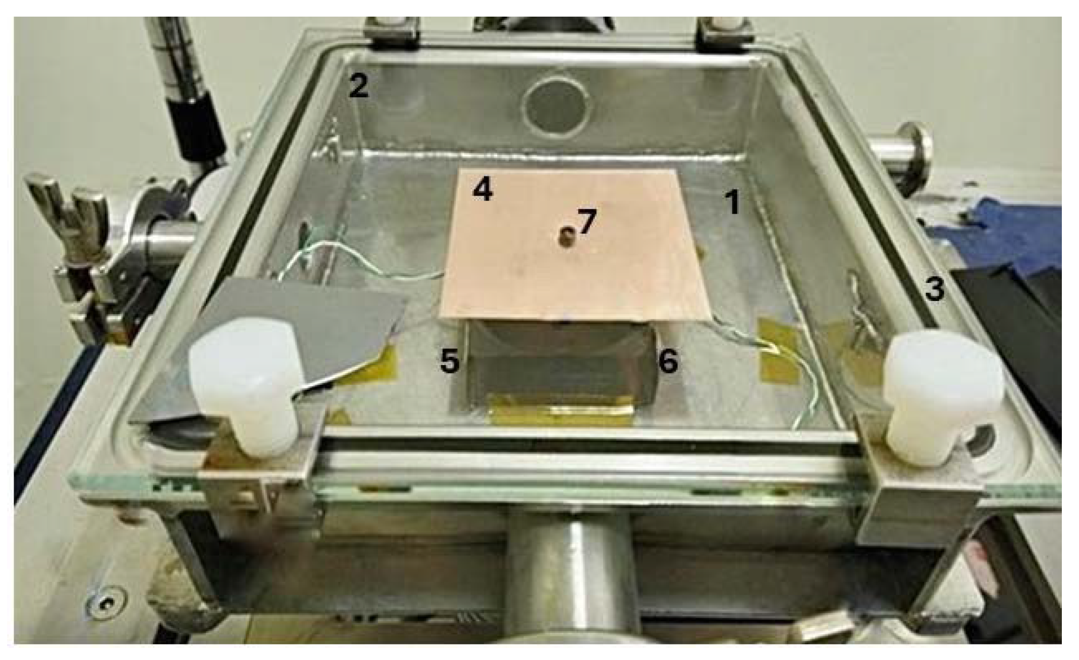
The experimental setup for the SSA sample’s emissivity measurements, considered in this manuscript is depicted in
Figure 1 and it is routinely used to assess the SSA properties also during aging tests (Caldarelli et al., 2021).
It consists of a rectangular stainless steel vacuum chamber (n° 1 in
Figure 1) sealed by a removable glass cover (n°2 in
Figure 1). A vacuum seal is achieved using a Viton O-Ring (n°3 in
Figure 1), which is compressed by the glass plate. The chamber operates under a high-vacuum regime obtained through a turbo-molecular pumping system. Flat absorber samples (n°4 in
Figure 1), with a maximum dimension of 210 cm
2 (14 cm x 15 cm), are placed inside the vacuum chamber.
The procedure involves obtaining a calorimetric measurement of temperature-dependent thermal emittance by monitoring the instantaneous temperature variation of the sample during the cooling phase after it has been heated to stagnation temperature by the LED system’s irradiated power.
The temperatures of the sample, cover glass, and chamber walls are measured using K-type thermocouples and read out using a USB module (National Instruments 9211). The sample thermocouple is crimped to a lug and screwed to the central hole of the sample using an M3 stainless steel nut and bolt (n°7 in
Figure 1). The glass and chamber temperature sensors are placed on the vacuum side to ensure that the external air convection, whether natural or forced, does not affect the temperature measurements.
In this case, the calorimetric equation used to obtain the thermal emittance of the sample under analysis can be written, under some approximations, as follows:
where m
s, A
s and c
ps(T
s) represent the mass, the surface and the temperature-dependent heat capacity of the analyzed sample respectively; m
th and c
pth(T
s) are the mass and the temperature-dependent capacity of the sample thermocouple fastening bolt and nut; T
s, and T
box (K) denote the sample temperature and the average temperature of glass and vessel of the MTB vacuum chamber, respectively, while 𝜎 is the Stefan- Boltzmann constant. ε
s represents the thermal emittance of the sample that is the objective of the measure and the factor 2 indicates that the upper and lower surfaces of the samples have the same thermal emittance.
Other causes of thermal losses are explicitly ignored in this approach.
The reliability of thermal emittance measurements during the cooling phase is limited by experimental noise. The more the sample temperature decreases, the more the measured temperature variation per unit of time becomes comparable to the thermocouple resolution, resulting in increased error and noise. A moving average of the measured data is used to reduce noise, and a linear (first-order) fit is applied to represent the total thermal emittance of the sample. As discussed in (D’Alessandro et al., 2022), to obtain reliable measurements, the data acquisitions are recorded from stagnation temperature down to a minimum absorber temperature of 100 °C; a temperature region where the sample power dissipated by thermal radiation is more than one order of magnitude higher than the other thermal exchange mechanisms and justify the assumption made in Equation (1).
However, for cases where the sample emitted power during the cooling phase is not sufficiently high to disregard these other heat exchange mechanisms, it is crucial to account for them. These additional mechanisms arise from the interaction between the elements of the experimental setup and the sample under analysis. When dealing with very low-emissive materials or samples with dimensions smaller than 210 cm², neglecting these additional thermal losses can lead to non-negligible errors in the thermal emittance value of the analyzed sample.
2.1. Calorimetric Balance Equation for Very Low-Emissive Materials
The sample, supported by some stainless steel springs in the vacuum chamber, experiences conductive cooling by these supports. A thermocouple, attached via an M3 bolt to the sample’s center, affects cooling due to its conductive and irradiative properties. These factors, neglected in the calorimetric Equation (1), are critical for accurately determining the thermal emittance of low-emissive materials as sample size and emittance decrease.
For such samples, it’s necessary to revise the calorimetric equation (Equation (1)) to include these considerations.
In this equation, the term ATL (Ts, Tbox) represents the Additional Thermal Losses and accounts for the fraction of the cooling power exchanged due to the heat transfer mechanisms mentioned above and neglected in Equation (1). In the study by (D’Alessandro et al., 2022), the negligibility of ATL for large area samples was estimated and demonstrated; however, the development of a precise model to evaluate such losses with the accuracy required for their subtraction in Equation (2) proved to be unfeasible. Consequently, we have opted for an experimental evaluation of these losses, as detailed in the following section.”
2.2. Procedure for Quantification of the Additional Thermal Losses Function
The inclusion of the ATL (Ts, Tbox) term in the thermal balance, adds an unknown term to the Equation (2) other than εs(Ts). Hence it becomes imperative to ascertain the functional expression for additional thermal losses in order to solve the complete calorimetric equation.
To determine the ATL expression, the adopted methodology involves measuring at least two samples possessing identical thermal emittance but varying in dimensions. Under these circumstances, the thermal emittance can be derived by assuming that the ATL remains consistent across these different measurements. These assumptions, which will be subsequently validated by measuring a larger set of samples, enable the determination of both the thermal emittance and the ATL term by solving a system of two equations with two unknowns:
In Equation (3), the subscripts 1 and 2 indicate that the two samples have different areas and different masses; all the other parameters are assumed to be identical.
The subsequent section will present the outcomes obtained from bulk copper samples of distinct dimensions. Calorimetric measurements were performed on four squared bulk copper samples having different surface areas. For each pair of samples composed of the same material but exhibiting different dimensions, the system of Equation (3) was solved, considering that when the sample and box temperatures (Ts, Tbox) are identical, the thermal emittance εs should be the same. The reduction process occurring in copper oxides under high vacuum conditions at 300 °C (Lee et al., 2003) is crucial to ensure the absence of oxidation on the sample surfaces, which, in turn, guarantees the same thermal emittance among the samples.
For the set of four samples with different dimensions under analysis, six possible combinations of two elements arise. Solving the system (Equation (3)) for these six distinct combinations yields six ATL (Ts, Tbox) curves, which will be presented and discussed in the ensuing section.
3. Results
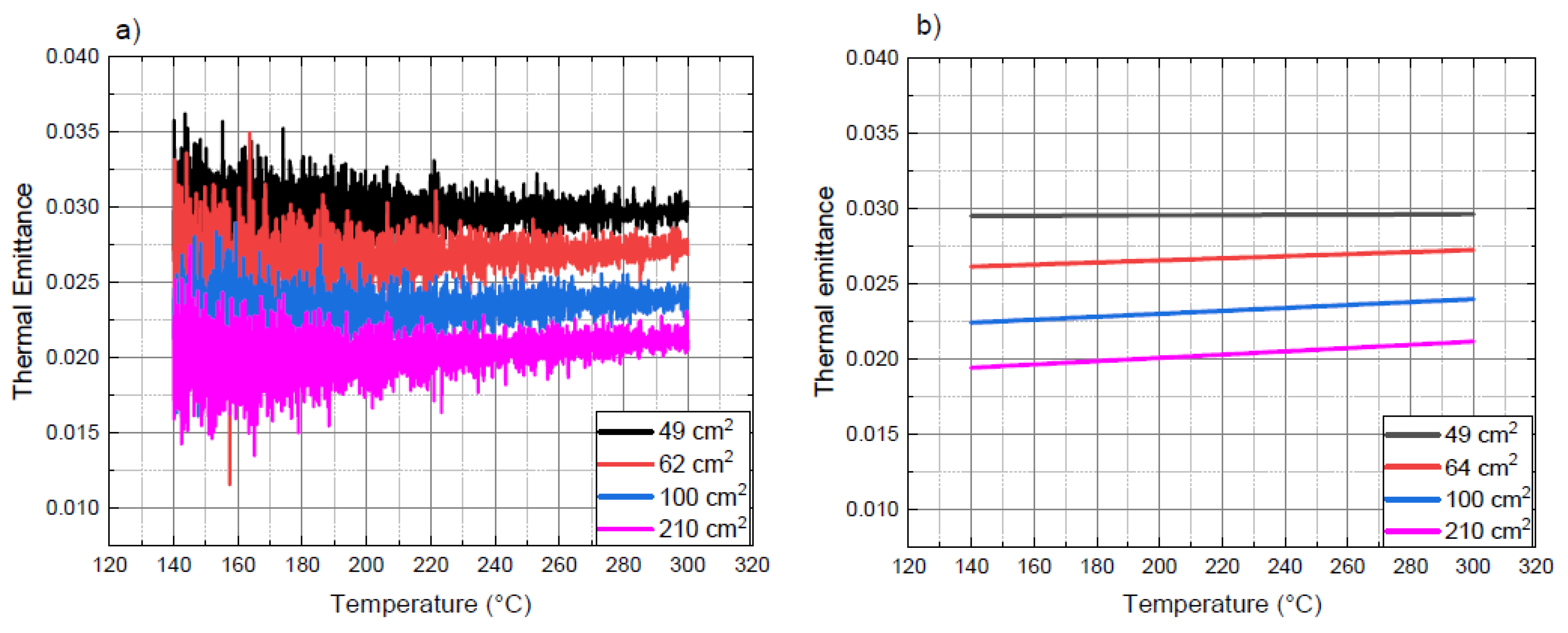
Figure 2 shows the results of thermal emittance measurements conducted on bulk copper (Cu) samples of various dimensions (210 cm², 100 cm², 64 cm², and 49 cm²), obtained neglecting the ATL contribution in the calorimetric balance equation (Equation (1)). Despite being the same material, different sample sizes analyzed by Equation (1) return different thermal emittance values.
Samples show a pronounced effect of additional thermal losses that, if not considered, lead to an overestimated thermal emittance, especially in smaller samples.
Figure 2b shows the results of the fitting procedure on the raw data presented in
Figure 2a.
The trend of ATL (Ts, Tbox) was obtained by determining the copper samples cooling power during the calorimetric measurements and resolving the system of Equation (3).
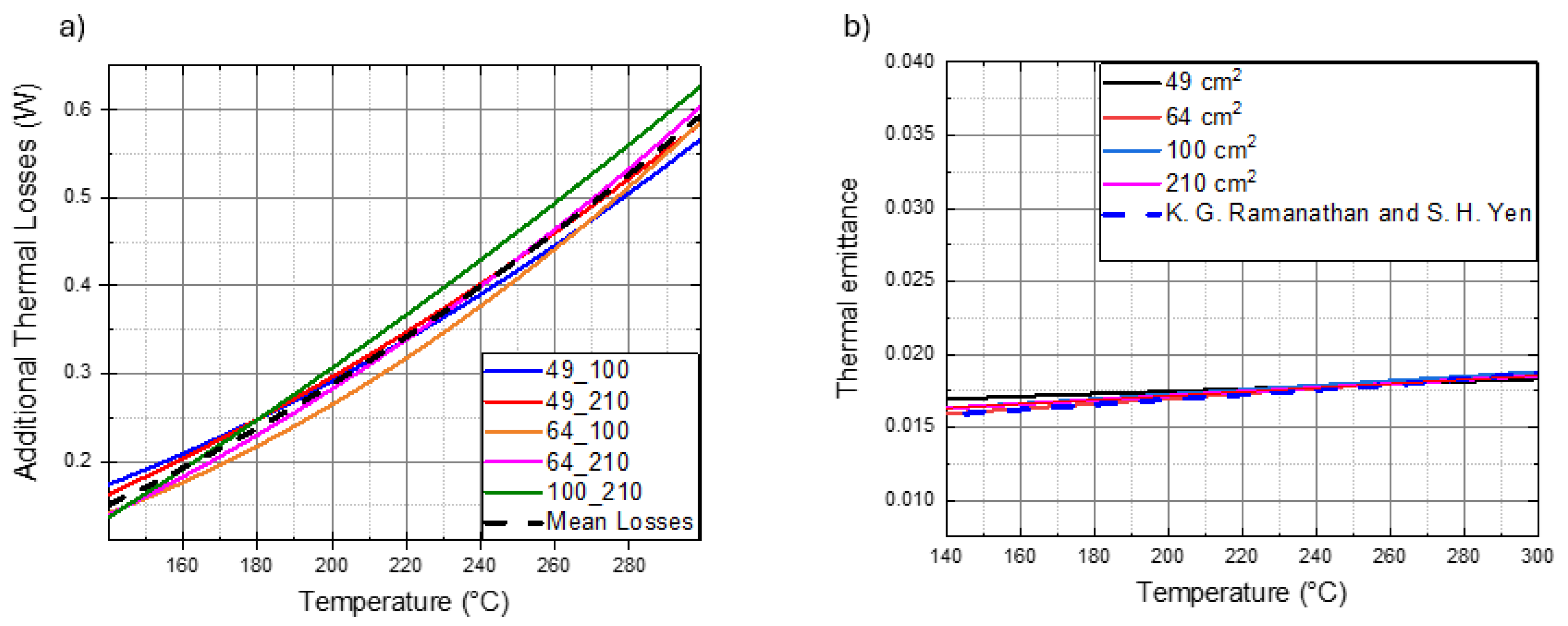
Figure 3 displays the ATL curves (continous lines) as a function of the absorber sample temperature.
The variations in box temperature (Tbox) with respect to the sample temperature (Ts) were negligible during the measurements of samples of different dimensions. Thus, the ATL function is only represented with respect to the sample temperature.
In the legend of the graph, each curve is indicated by the dimensions (in cm²) of the pair of samples whose balance equation is coupled in the system (3). The ATL obtained are very similar, with a maximum variation of less than 10% with respect to the average, supporting the hypothesis that ATL does not depend on the sample dimensions but only on its temperature. Under this hypothesis, the average curve was calculated (dashed black line in
Figure 3) and considered to obtain the function to be incorporated into the complete calorimetric balance equation (Equation (2)).
Considering that the apparatus works in high vacuum, we can safely assume (Gaudino et al. 2023) that the additional thermal losses consist of two terms: a radiative term due to different thermal emittance of bolt and nut, proportional to the fourth power difference between the sample and box temperatures according to the Stefan-Boltzmann law, and a conductive term, proportional to the temperature difference between the sample and box. The ATL expression can be assumed to have the following form:
For copper (Cu) samples the coefficients z
1 and z
2 are obtained by fitting the experimental average ATL (T
s, T
box) curve shown in
Figure 3a to Equation (4).
The ATL expression for copper samples in the present configuration is:
Using the previous expression of ATL (T
s, T
box), Equation (2) can now be used to calculate the thermal emittance curves for the copper samples: the results are reported in
Figure 3b. These curves overlap with each other and with the copper hemispherical emissivity curve found in the literature (Ramanathan et al., 1977) (also reported in
Figure 3b) at high temperatures and differ by less than 0.003 at 150°C.
4. Discussion
Once the expression for the ATL function (ATL (Ts, Tbox)) is obtained for copper samples, it is possible to compare the magnitude of losses introduced by the MTB experimental setup to the emitted power from samples of various dimensions. This comparison allows us to determine when it is possible to neglect the ATL term in the calorimetric balance equation as, for instance, it was correctly done in (D’Alessandro et al., 2022). Furthermore, it helps to identify situations where, despite considering the ATL term, its significant influence on the measurements prevents the accurate deduction of the sample’s emitted power from the total thermal losses.
4.1. Weight of Additional Thermal Losses on Measurements: Assessing the Influence of Sample Temperature, Dimension, and Thermal Emittance
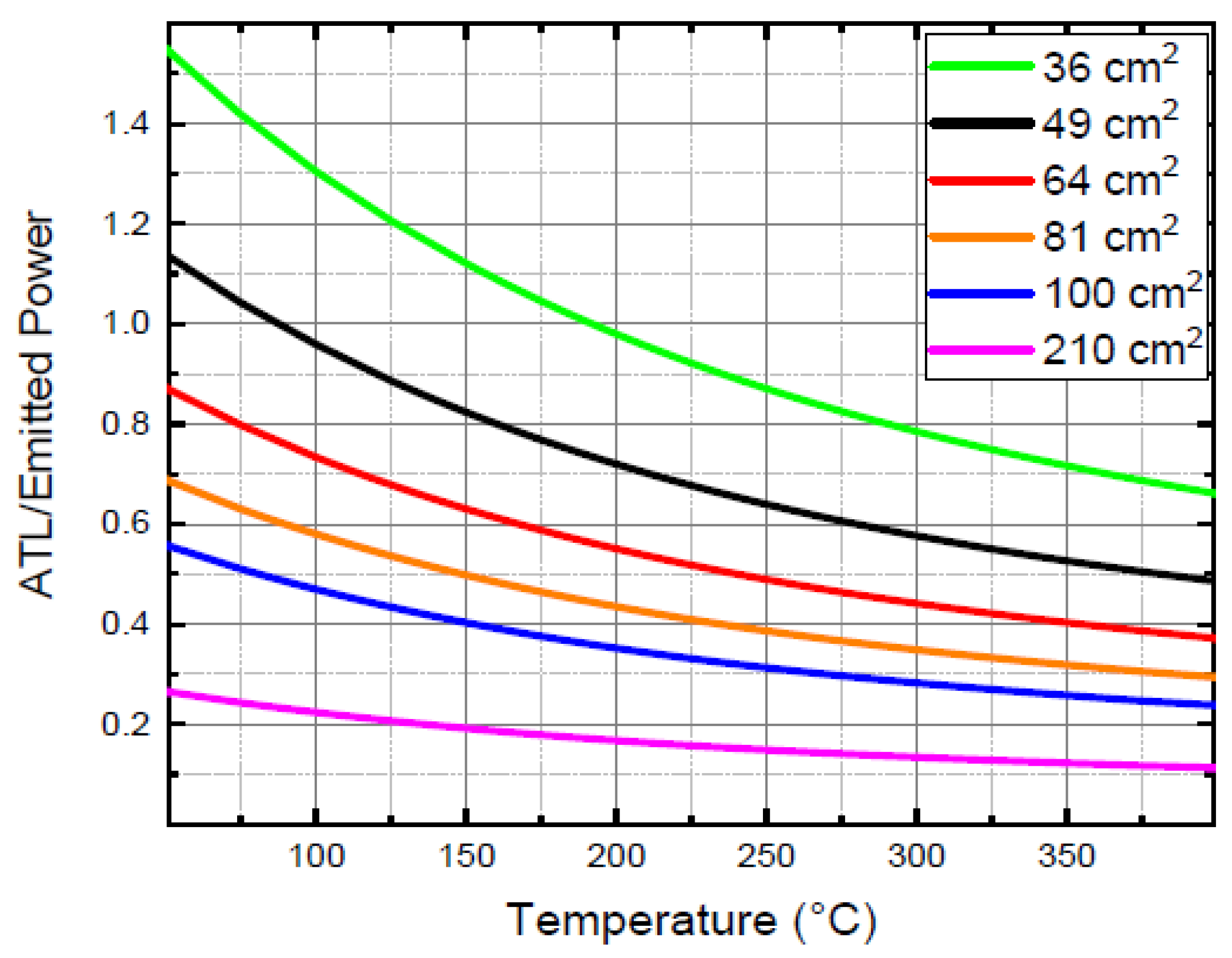
Figure 4 represents the ratio between ATL and the sample emitted power (both calculated in watts) as a function of the absorber temperature for samples of different areas. A ratio of 1 indicates that the losses induced by the experimental setup match the power emitted by the sample during a cooling phase, and reliable measurements can be obtained for a ratio below 1.
Figure 4 illustrates that with the current configuration, considering the ATL term in the calorimetric balance equation, it is possible to assess the thermal emittance of copper samples with dimensions higher than 49 cm² at temperatures higher than 150°C: copper samples having an area smaller than 49 cm
2 have ATL comparable to/or larger than the emitted power from the sample, making the measurement too influenced by the subtraction of these additional dissipations.
It is interesting to observe that the ratio reported in
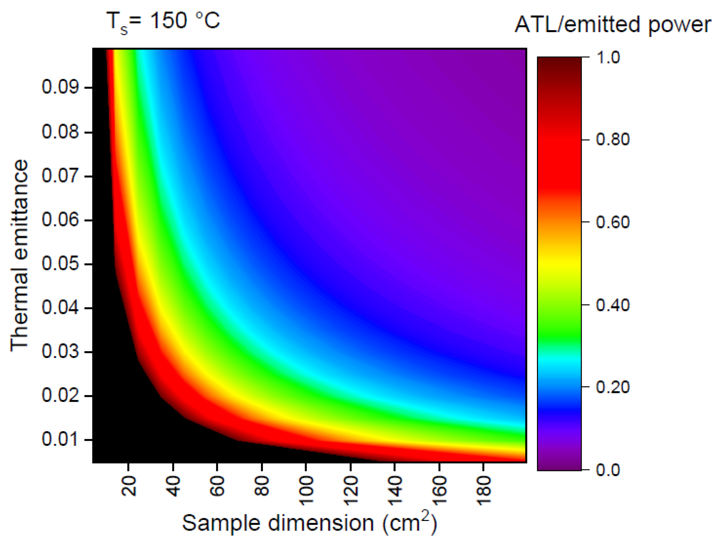
Figure 4 reduces with temperature, meaning that the measurement is more reliable at high temperatures. At a fixed temperature of the sample, the ATL/emitter power ratio can be graphically represented as a function of the sample dimension and thermal emittance and used to establish the minimum dimension that can be correctly measured for a given thermal emittance.
The results for a temperature of 150°C are depicted as a color map in
Figure 5. In samples with dimensions larger than 200 cm² and a thermal emittance at 150 °C exceeding 0.09, represented by the violet region in the colormap (similar to the samples tested in (D’Alessandro et al., 2022)), the ratio of ATL to emitted power is approximately zero. This indicates that the ATL term can be disregarded in the calorimetric balance equation. However, as the sample dimensions and/or the thermal emittance decrease, the colormap transitions into the green, yellow, and red regions, pointing out a greater impact of ATL in the sample cooling process. The black region in
Figure 5 denotes the scenario where the ATL/emitted power ratio exceeds 1.
Figure 5 is crucial for understanding the minimal thermal emittance that can be accurately measured using samples of specific dimensions as delineated in Equations 2 and 5. For samples with a copper substrate, accurate evaluation of thermal emittance is feasible within the violet, blue, and yellow regions of the colormap. Considering the ATL, to measure thermal emittance values lower than 0.02 samples measuring 40 cm² cannot be used.
The correct determination of the ATL term is pivotal for thermal emittance measurements by the calorimetric method for SSA deposited on copper, which in turn is essential to assess the radiative losses in SSA and their solar energy conversion efficiency as described in the next subsection.
4.2. Correction of Measured Thermal Emittance of Selective Solar Absorbers Deposited on Bulk Copper Substrate
The calorimetric equation in the case of SSA deposited on copper contains two radiative terms for the two sample surfaces: the SSA and the copper substrate. The thermal emittance of the substrate and the ATL can be accurately measured using the method described in this paper and the only unknown in the calorimetric equation remains the thermal emittance of the SSA under measurement.
In (De Maio et al., 2022) it was presented a novel approach to SSA design and optimisation based on a genetic algorithm and Cr2O3 and Cr multilayers. These SSAs were meticulously designed to enhance the efficiency of solar-to-thermal conversion at intermediate temperatures within an HVFPC and deposited by sputtering.
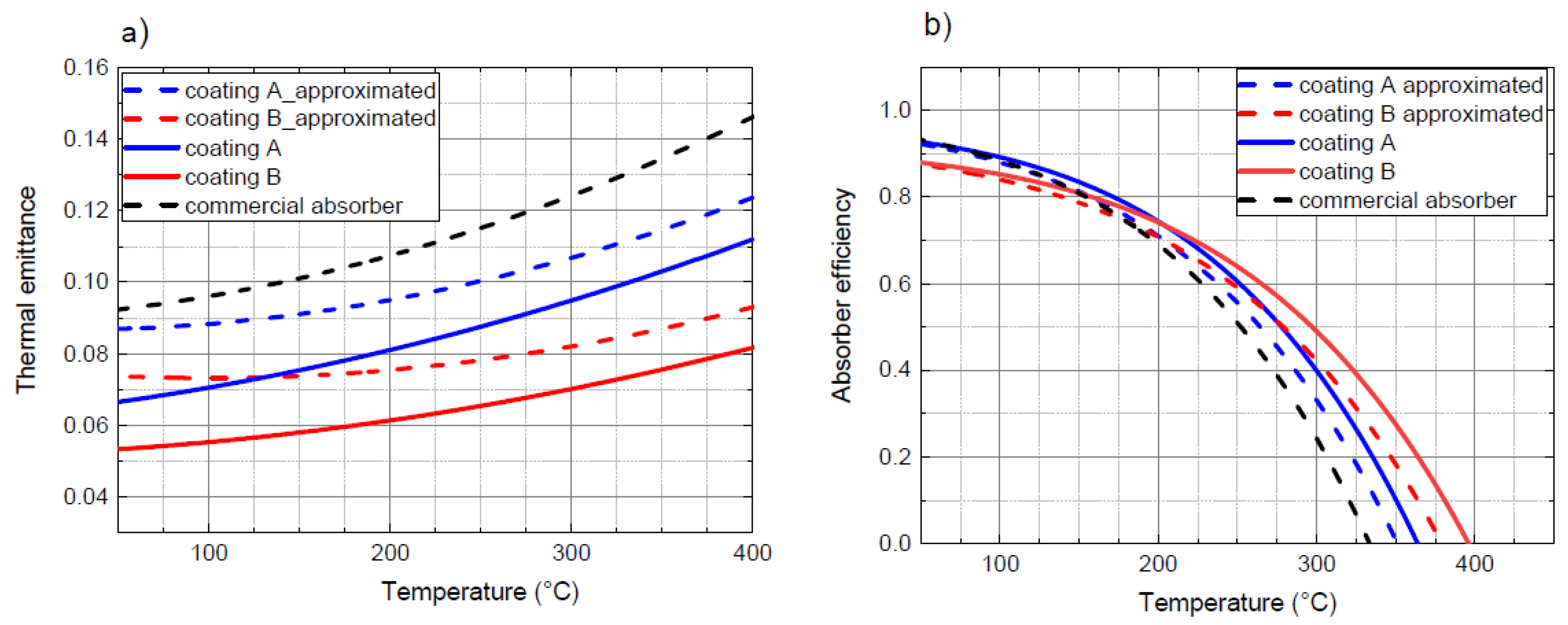
Two optimized configurations of SSA samples, denoted as coating A (optimized for operation at 200 °C) and coating B (optimized for operation at 300 °C), were deposited on copper substrates with a dimension of 100 cm² (De Maio et al., 2021b). The thermal emittance of the SSAs was measured using the MTB apparatus, and the absorber efficiencies were evaluated under specific conditions: solar irradiance of 1000 W/m² and an ambient temperature of 20 °C (eq. (5) in (De Maio et al., 2021b)). The measured thermal emittance values, depicted in
Figure 6 a) with dashed lines, were compared to those of a commercial absorber (represented by the black line). However, the measured thermal emittance of the SSAs was approximately 0.04 higher than the values predicted by simulations for both multilayers.
This high discrepancy between the expected and measured thermal emittance values for coating A and B was unclear. It can now be attributed to the neglect of ATL influence in evaluating thermal emittance by solving Equation (1). To address this issue, incorporating the expression of ATL (T
s, T
box) specifically for samples with copper substrates, the thermal emittance values for coating A and B were reassessed and are presented in
Figure 6a) as continuous lines. Furthermore, these reassessed values were utilized to compute the absorber efficiency displayed in
Figure 6b).
The discrepancy between the measured and simulated thermal emittance values was significantly reduced to 0.025. This remaining deviation can be attributed to the presence of layer thickness variation on a large-area sample. In fact, the SSAs are usually deposited using Phisycal Vapor Deposition (PVD) techniques such as magnetron sputtering, and a good layer thickness uniformity is obtained on an area that is a fraction of cathode dimensions (10 cm diameter in our case). Correctly measuring the thermal emittance on smaller samples will allow for the deposition of SSA with a better thickness uniformity and avoid such uncertainty.
To reduce the minimal dimension required to correctly measure the extremely low thermal emittance in newly developed SSA, the radiative and conductive contributions to the ATL have to be minimized. This can be achieved by reducing the irradiating surface (miniaturizing the thermocouple elements) and/or using low emittance material (i.e., by adding a copper layer on the bolt and nut used to connect the thermocouple) and adopting extremely low conductive materials (such as ceramic) to support the sample.
5. Conclusions
The manuscript presents significant advances in measuring thermal emittance for extremely low-emissive materials, which are essential to correctly assess the energy conversion efficiency in newly developed Selective Solar Absorbers (SSAs). The methodology enables accurate measurement of thermal emittance values for copper samples, addressing the limitations posed by sample size. The measured copper thermal emittance values align closely with the literature data, underscoring the method’s effectiveness in measuring thermal emittance values below 0.02 with an error lower than 0.003.
Also, the relation between the sample dimensions and minimal thermal emittance measurable value has been highlighted, and indications to further reduce the minimal measurable sample dimensions have been provided. Reducing the bold and nut dimensions from M3 to M2 would reduce the emitting surface by about a factor of two, and a factor of three can be obtained by coating the stainless steel bolt and nut with a copper film, resulting in a minimal dimension of about 8 cm2 to measure thermal emittance values of 0.02. The new system will allow for determining the thermal emittance of SSA deposited on Cu samples with dimensions of 3x3 cm2, eliminating the non-uniformity problem present in R&D deposition systems, which are often limited to dimensions below 5 cm in diameter (two inches).
Our findings are essential for correctly assessing the radiative properties in materials with very low thermal emittance, such as SSA for HVFPCs, and determining the energetic performance of the HVFPCs equipped with the new SSAs also in previously produced and measured SSAs.
Looking forward, the manuscript extends the applicability of this method to a broader range of materials and dimensions, enhancing the precision and utility of thermal emittance measurements in solar thermal applications where the radiative properties of SSA are fundamental in determining solar conversion efficiency.
Acknowledgments
This study was supported by the Eurostar Program powered by EUREKA and the European Community (Project ESSTEAM reference E! 115642, CUP B69J21036070005).
| Nomenclature |
| A |
surface (cm2) |
| cp
|
heat capacity (J/kgK) |
| ε |
Thermal emittance |
| σ |
Stefan-Boltzmann constant (W/m2K4) |
| m |
Mass (kg) |
| z1
|
Additional radiative thermal loss coefficient |
| z2
|
Additional conductive thermal loss coefficient |
| Abbreviations |
| ATL |
Additional Thermal Losses |
| MTB |
Mini Test Box |
| Subscripts |
| s |
Sample |
| th |
Thermocouple |
References
- Ablewski, P., Bober, M., Zawada, M., 2020. Emissivities of vacuum compatible materials: towards minimising blackbody radiation shift uncertainty in optical atomic clocks at room temperatures. Metrologia 57, 035004. [CrossRef]
- Caldarelli, A., D’Alessandro, C., De Maio, D., De Luca, D., Gaudino, E., Musto, M., Di Gennaro, E., Russo, R., 2021. Characterization and thermal aging tests of Cr based multilayer for unconcentrated solar thermal applications. Thin Solid Films 735, 138870. [CrossRef]
- Caldarelli, A., Gaudino, E., De Luca, D., Farooq, U., Musto, M., Di Gennaro, E., Russo, R., 2023. Low emissivity thin film coating to enhance the thermal conversion efficiency of selective solar absorber in high vacuum flat plate collectors. Thin Solid Films 764, 139632. [CrossRef]
- Cao, F., McEnaney, K., Chen, G., Ren, Z., 2014. A review of cermet-based spectrally selective solar absorbers. Energy Environ. Sci. 7, 1615. [CrossRef]
- Cheng, S.X., 1989. Total hemispherical emissivities of cobalt and nickel in the range 350–1000 K. Experimental Thermal and Fluid Science 2, 165–172. [CrossRef]
- D’Alessandro, C., De Maio, D., Caldarelli, A., Musto, M., Di Giamberardino, F., Monti, M., Mundo, T., Di Gennaro, E., Russo, R., Palmieri, V.G., 2022. Calorimetric testing of solar thermal absorbers for high vacuum flat panels. Solar Energy 243, 81–90. [CrossRef]
- Das, P., Rudra, S., Maurya, K.C., Saha, B., 2023. Ultra-Emissive MgO-PVDF Polymer Nanocomposite Paint for Passive Daytime Radiative Cooling. Adv Materials Technologies 2301174. [CrossRef]
- De Maio, D., D’Alessandro, C., Caldarelli, A., De Luca, D., Di Gennaro, E., Russo, R., Musto, M., 2021a. A Selective Solar Absorber for Unconcentrated Solar Thermal Panels. Energies 14, 900. [CrossRef]
- De Maio, D., D’Alessandro, C., Caldarelli, A., De Luca, D., Gennaro, E.D., Casalino, M., Iodice, M., Gioffre, M., Russo, R., Musto, M., 2021b. Multilayers for efficient thermal energy conversion in high vacuum flat solar thermal panels. Thin Solid Films 735, 138869. [CrossRef]
- De Maio, D., D’Alessandro, C., Caldarelli, A., Musto, M., Russo, R., 2022. Solar selective coatings for evacuated flat plate collectors: Optimisation and efficiency robustness analysis. Solar Energy Materials and Solar Cells 242, 111749. [CrossRef]
- Gaudino, E., Caldarelli, A., Russo, R., Musto, M., 2023. Formulation of an Efficiency Model Valid for High Vacuum Flat Plate Collectors. Energies 16, 7650. [CrossRef]
- Herguedas, N., Carretero, E., 2023. Evaluation of low-emissivity coatings with single, double, and triple silver layers. Solar Energy Materials and Solar Cells 263, 112592. [CrossRef]
- Jelle, B.P., Kalnæs, S.E., Gao, T., 2015. Low-emissivity materials for building applications: A state-of-the-art review and future research perspectives. Energy and Buildings 96, 329–356. [CrossRef]
- Lee, S.Y., Mettlach, N., Nguyen, N., Sun, Y.M., White, J.M., 2003. Copper oxide reduction through vacuum annealing. Applied Surface Science 206, 102–109. [CrossRef]
- Mahmoudinezhad, S., Sadi, M., Ghiasirad, H., Arabkoohsar, A., 2023. A comprehensive review on the current technologies and recent developments in high-temperature heat exchangers. Renewable and Sustainable Energy Reviews 183, 113467. [CrossRef]
- Mi, S.-T., Zhang, Y.-C., Fu, X.-B., Li, Q., Kong, T., 2023. Study on infrared emissivity model based on perturbation method and Kirchhoff approximation and its application in aluminum alloy welding. Optik 290, 171347. [CrossRef]
- Monte, C., Gutschwager, B., Morozova, S.P., Hollandt, J., 2009. Radiation Thermometry and Emissivity Measurements Under Vacuum at the PTB. Int J Thermophys 30, 203–219. [CrossRef]
- Pratesi, S., De Lucia, M., Meucci, M., Sani, E., 2016. Structural and optical properties of copper-coated substrates for solar thermal absorbers. Superlattices and Microstructures 98, 342–350. [CrossRef]
- Querry, M.R., 1985. Optical constants, Contractor Report.
- Ramanathan, K.G., Yen, S.H., Estalote, E.A., 1977. Total hemispherical emissivities of copper, aluminum, and silver. Appl. Opt. 16, 2810. [CrossRef]
- Van Nijnatten, P.A., Hutchins, M.G., Kilbey, N.B., Roos, A., Gelin, K., Geotti-Bianchini, F., Polato, P., Anderson, C., Olive, F., Köhl, M., Spragg, R., Turner, P., 2006. Uncertainties in the determination of thermal emissivity by measurement of reflectance using Fourier transform spectrometers. Thin Solid Films 502, 164–169. [CrossRef]
- Wen, C.-D., Mudawar, I., 2006. Modeling the effects of surface roughness on the emissivity of aluminum alloys. International Journal of Heat and Mass Transfer 49, 4279–4289. [CrossRef]
- Xu, J., Wang, J., Lu, L., Gao, M., 2022. Study on the infrared emissivity of nonstoichiometric titanium chromium nitride films. Thin Solid Films 754, 139303. [CrossRef]
- Xu, K., Hao, L., Du, M., Mi, J., Yu, Q., Li, Shuai, Wang, J., Li, Shijie, 2020. Thermal emittance of Ag films deposited by magnetron sputtering. Vacuum 174, 109200. [CrossRef]
- Yu, K., Wang, G., Li, L., Zhang, K., Liu, Y., 2020. A new experimental apparatus for polarized spectral emissivity measurement in a controlled environment. Infrared Physics & Technology 111, 103572. [CrossRef]
- Zhang, K., Xu, Y., Wu, X., Yu, K., Liu, Y., 2022. A new approach for accurately measuring the spectral emissivity via modulating the surrounding radiation. Journal of Quantitative Spectroscopy and Radiative Transfer 288, 108277. [CrossRef]
- Zhang, K., Zhao, Y., Yu, K., Liu, Y., 2018. Development of experimental apparatus for precise emissivity determination based on the improved method compensating disturbances by background radiation. Infrared Physics & Technology 92, 350–357. [CrossRef]
- Zhang, W.J., Qiu, J., Liu, L.H., 2015. Deviation characteristics of specular reflectivity of micro-rough surface from Fresnel׳s equation.
- Journal of Quantitative Spectroscopy and Radiative Transfer 160, 50–62. [CrossRef]
|
Disclaimer/Publisher’s Note: The statements, opinions and data contained in all publications are solely those of the individual author(s) and contributor(s) and not of MDPI and/or the editor(s). MDPI and/or the editor(s) disclaim responsibility for any injury to people or property resulting from any ideas, methods, instructions or products referred to in the content. |
© 2024 by the authors. Licensee MDPI, Basel, Switzerland. This article is an open access article distributed under the terms and conditions of the Creative Commons Attribution (CC BY) license (http://creativecommons.org/licenses/by/4.0/).
