2.1. Theoretical Basis of Object Analysis
Object design used in computer science consists in operating the objects which are the data together with the methods that is the functions describing the activities performed on the object [
12,
13,
14,
15,
16,
17,
18,
19,
20,
21,
22,
23,
24,
25,
26,
27,
28]. The object is the independent variable which stores the data, follows the instructions and cooperates with other objects by exchanging messages in order to realize all the functions of the modelled system. These are parts of computer programmes which store the data and perform a particular task. In a typical case, groups of objects called classes are created. They reflect common features of the objects. The object (object variable) is the element of a complex abstract structure called a class. The data stored by the object are attributes, the functions connected with them are methods. Some of the attributes and methods are private (local) and available only from the inside of the object. Others are public (global) available from the inside and outside of the object. The object with concrete values is called a concrete. The concrete includes its own characteristic values of variables. The class is the pattern defining the methods and variables which are to be the part of a given object type therefore the descriptions of methods and data appear only once in the definition of class.
The basic assumptions of the object design are as follows:
abstracting which is the process of defining the objects of the real world by means of simplified structures,
making hermetic – linking the data with the structures connected with them on the object level; the object cannot change the inner condition of other objects in an unexpected way,
polymorphism – the possibility to choose a particular method during its performance out of a lot of methods having the same name,
dynamic bonding – the possibility to give the same name to two objects of different classes,
inheritance which is the scheme of dependence between classes in which the classes may use methods and variables defined in the preceding classes – therefore defining a particular problem once and then using it repeatedly in other form is possible.
According to the inheritance property each class may have an arbitrary number of subclasses (the classes lower in the hierarchy) and at least one super-class i.e. the class one level higher. The class may inherit the attributes from one or a few super-classes [
12,
13,
14].
Object programming enables the use of the same techniques used to create all the objects included in the application regardless of the place in the hierarchy. The hierarchical structure enables easier analysis and modification of objects. It makes it possible to observe the interrelations between the objects, the view of their properties or methods and free copying. However, the object in machines design is a parameterized constructional form, inheriting all the necessary attributes from the classes or subclasses [
15].
For instance, the WHEEL_PAIR class may have such attributes as the axes_distance, alpha_angle, beta_angle, module, transmission ratio, etc. If the subclass of the class, called PINION, is defined it automatically inherits all the properties from the class WHEEL_PAIR, except for those which will be blocked. Moreover, new attributes may be defined in the subclass. They will characterize PINION as e.g. coefficient_x1, width_b1 etc.
Association is here the relation between the classes of objects. It may connect two or more classes of objects. It enables navigation between the objects connected by it in any direction. However, aggregation is a special case of association modelling the relation of the whole to its part. The objects are connected by means of aggregation if one of them is the part of the other and the cycle and time of their duration are the same.
The attributes of association characterize connections between the objects. For example, association SUB-ASSEMBLY between the objects SLOW-SPEED_SHAFT and the class WHEEL may be attributes of association SUBASSEMBLY_SLOW-SPEED.
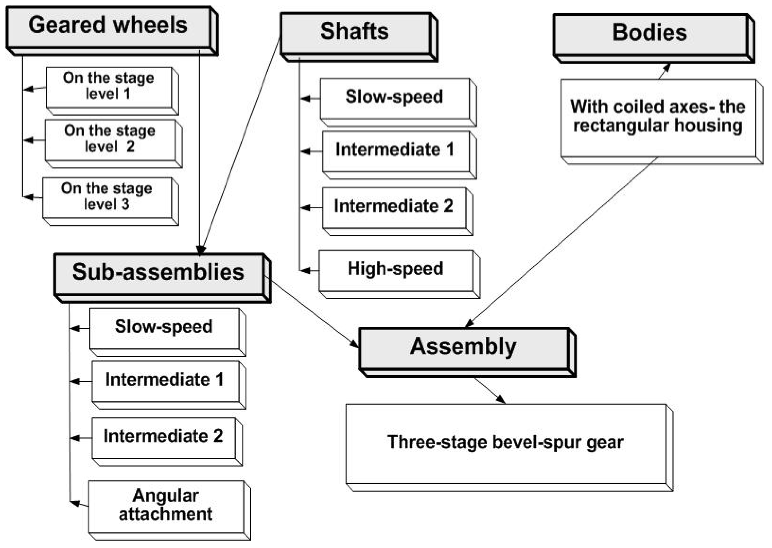
Figure 2 shows a few most important elements of objectivity of the gear being examined, such as:
super-class, where the set consists in a three-stage bevel-spur reducer,
the classes which are sub-assemblies, subclasses are geared wheels, shafts, bodies, and the forms of inheritance.
Figure 2.
State diagram of a three-stage bevel-spur gear.
Figure 2.
State diagram of a three-stage bevel-spur gear.
The methodology of object-oriented analysis of the gear size ranges presented in the article is the author’s own study. It uses the terms of objectivity for modelling, i.e. the analysis which is theoretical consideration which came into being in the designers mind and the synthesis together with the assessment as implementation.
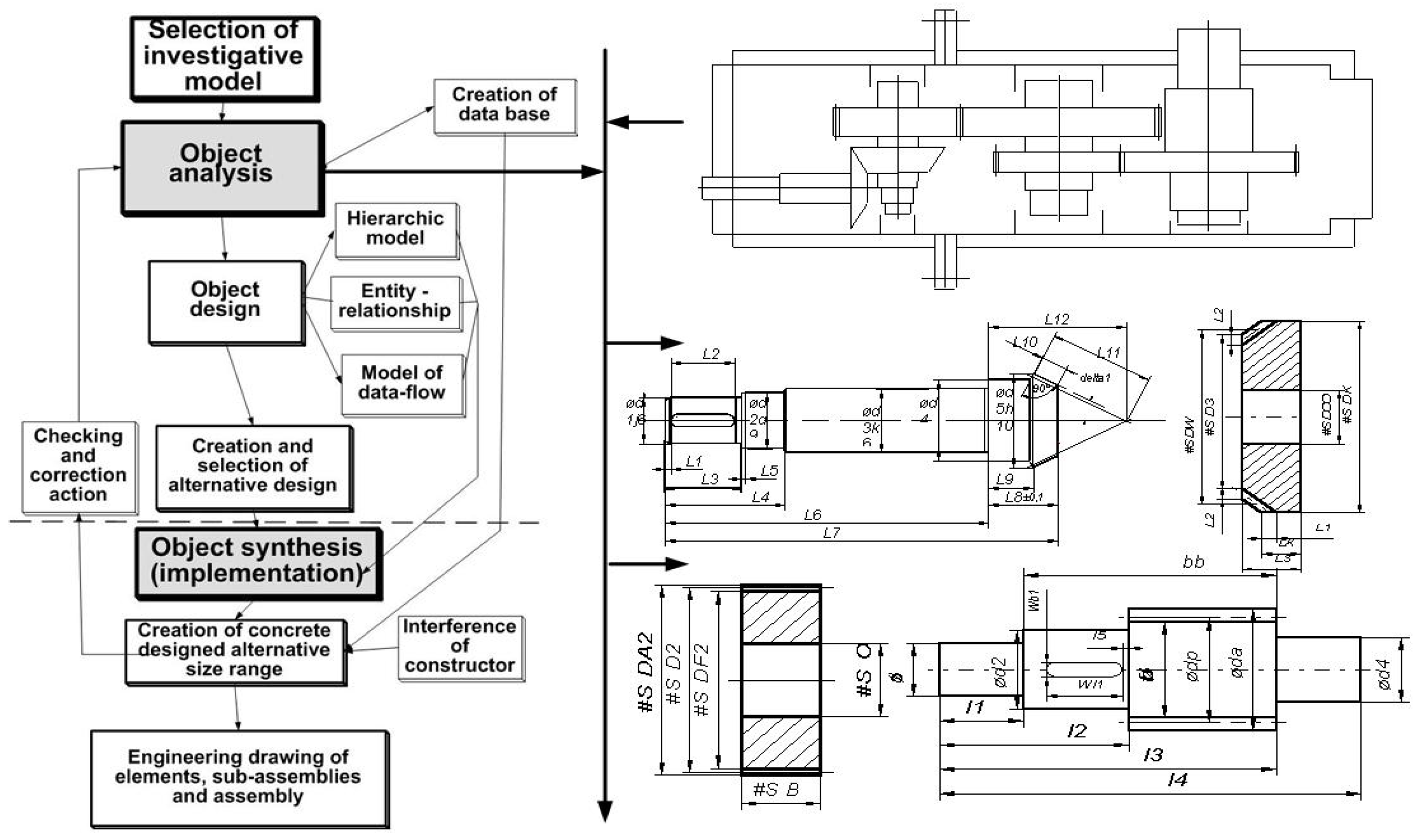
In the object analysis which is the topic of this article there is decomposition according to the rule “from general to detail view” (
Figure 3) of the designed assembly, e.g. a three-stage bevel-spur gear reducer into sub-assemblies and elements as well as selecting the super-classes, classes and sub-classes. The sub-classes are the elements such as geared wheels, shafts, bodies. The classes are sub-assemblies e.g. intermediate, high-speed. Super-classes are the kinds of assemblies e.g. a three-stage bevel-spur gear reducer.
As an exemplary solution, an investigative model which is a three-stage bevel-spur gear reducer has been chosen. Object analysis is based on previous engineering calculations whose results are in the data-bases. However, the object programming as shown in
Figure 3 is operating object, hierarchical, entity relationship and data flow models, creating and choosing variants. The examined issue was treated as a process attitude recommended by international standards of quality management ISO-9000:2001. The process, in this case object analysis, is a set of interrelated and interacting activities which change input into output.
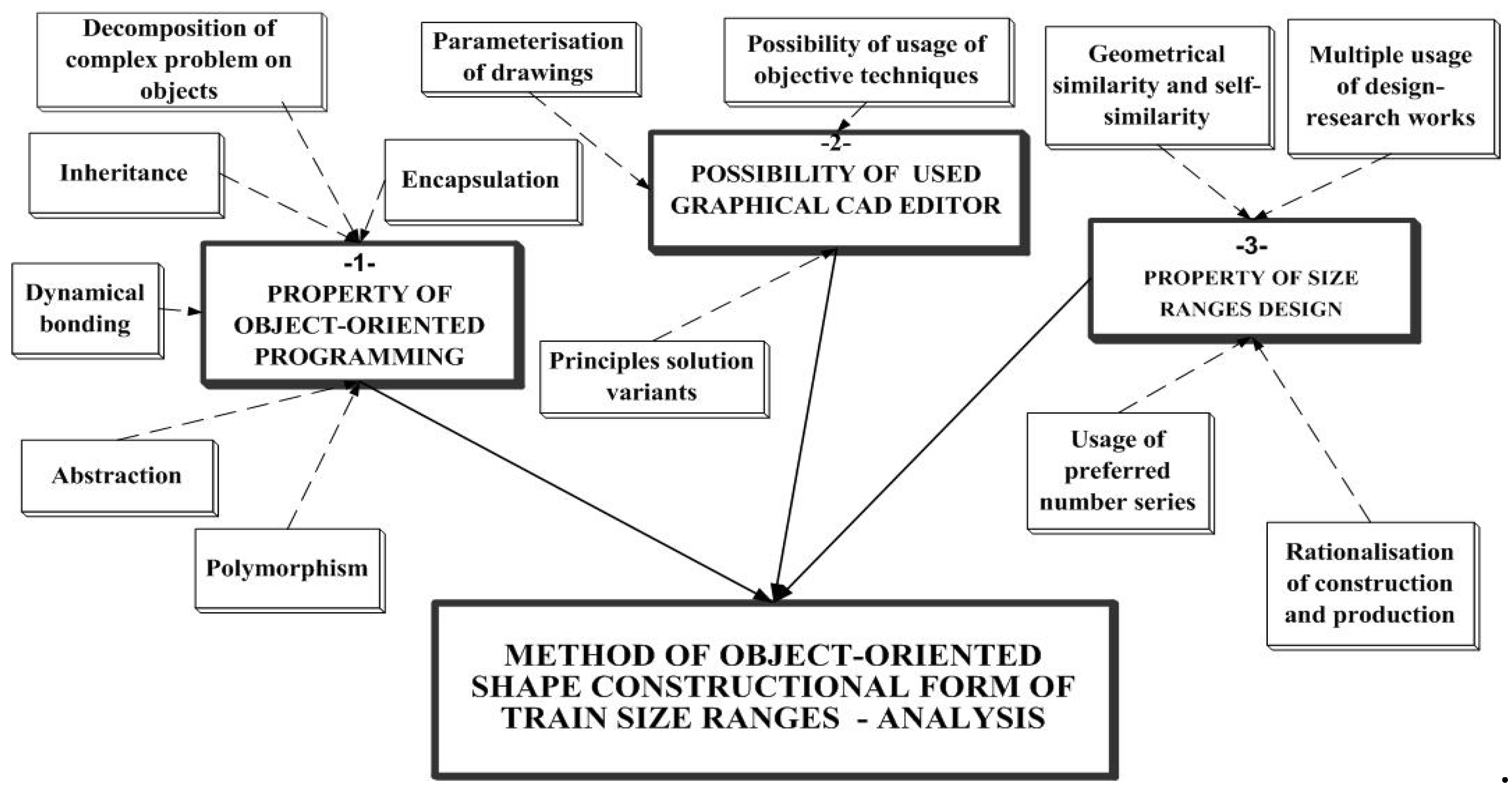
feature of object-oriented programming consisting in partition of a complex problem into objects which can be solved independently using its five basic qualities such as abstracting, inheriting, making hermetic, polymorphism and dynamic bonding,
possibilities of the graphical editor used, enabling among other things parameterization of drawings, the use of variant techniques and the possibility of using object techniques,
properties of size ranges design characterized by rationalization of the construction and production through single-time performing of project-research works including any big amount of values of consecutive units of size ranges and using probability laws,
geometrical and partial and taking into account a sequence of natural numbers.
Figure 4.
Elements making up the object analysis input.
Figure 4.
Elements making up the object analysis input.
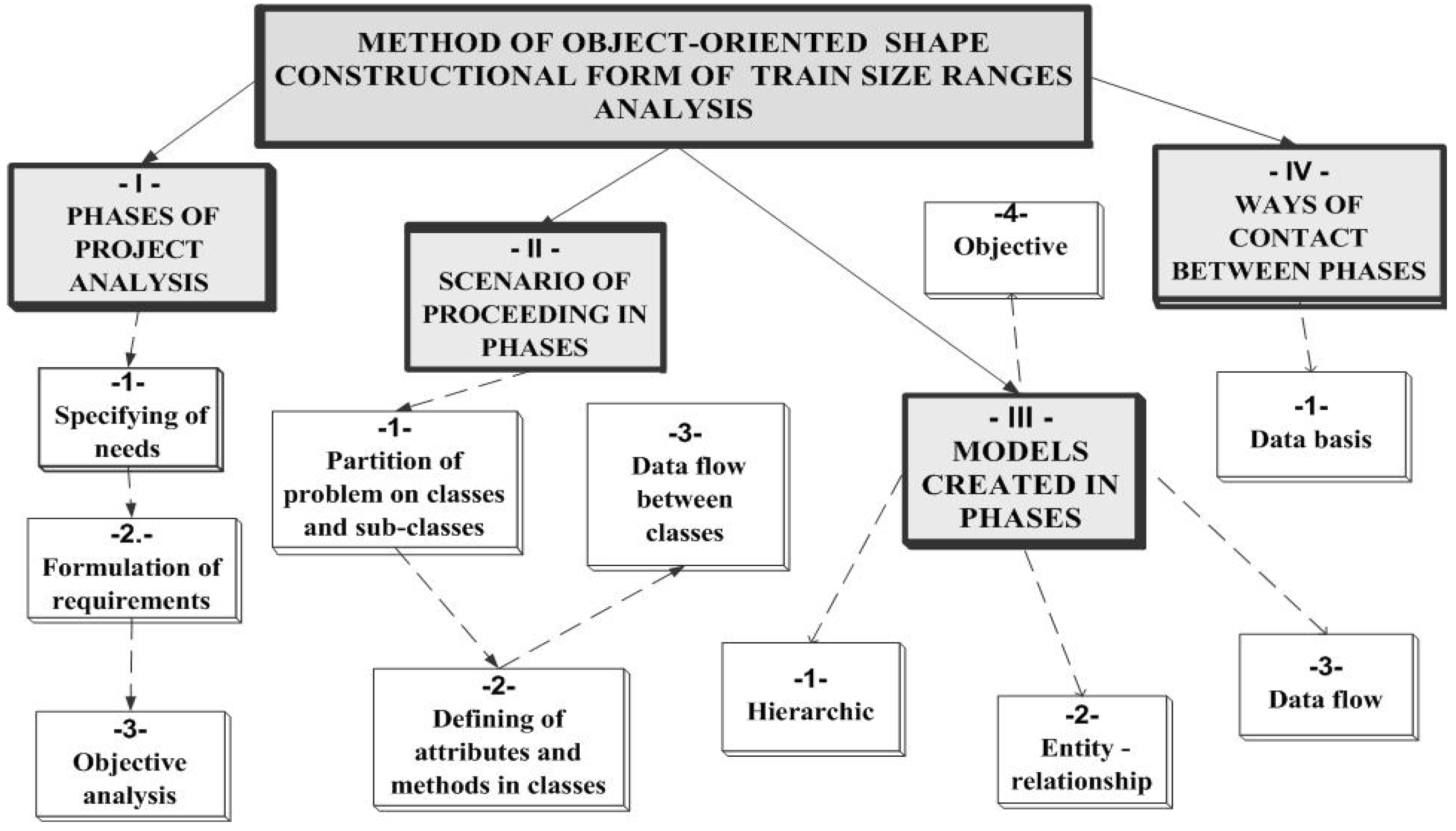
The process which transforms the above-mentioned qualities and capacities of object-oriented programming, size ranges design as well as graphical editor use is object analysis which determines the following elements (
Figure 5):
phases of analysis i.e. specifying the needs, formulating requirements, analysis,
the scenario of proceeding in phases consisting in partition of a problem into classes and objects, defining attributes and methods in particular classes, making up diagrams of data flow between the classes,
the models made up in phases are the models such as: hierarchical, entity-relationship, data-flow and object.
The result, output of the process of analysis to synthesis are the ways of contact between phases, such as object databases together with parameters and object models.
Figure 5.
Elements of object analysis process.
Figure 5.
Elements of object analysis process.
2.2. Design Phases of Analysis Stage and Scenario of Proceeding in Phases
Activities concerning the analysis phase which cause gathering of essential information for the task being solved should be objective and the least disrupted with subjectivity. They concern to such activities as: specification of needs, formulating requirements and analysis.
Identification of needs is especially connected with market research by the marketing service in order to accurately identify the needs which are to be satisfied. Various tools are here used which will let properly direct the project problem and then determine aims and constructional tasks. Hierarchic methods are here used which allow selecting aims or main and derivative tasks.
Formulation of requirements is making the list of requirements, restrains and assessment criteria which eventually leads to clear-cut formulating of the project problem.
After having identified the existing or predicted market needs, there follows the study of requirements directed at project work.
The aim of object analysis is to describe (decomposition) of the object which is to undergo further stages of design process. It uses specified needs and formulated requirements in connection with various structural connections.
Creating the constructional forms elements of the problem solved involved the following stages in methodology:
decomposition of the problem into classes and objects,
determining attributes and methods in classes,
data-flow between the classes.
Classes and objects assigned to them are connected with the concept of a given field of application. In order to find appropriate classes and objects, i.e. to identify them, there must be the possibility to clearly specify and define the concepts. Also, when finding the objects, it is useful to define the data or determine the processes (Rumbaugh 1991).
For the need of partition of the problem solved e.g. the project of gear size range, the methodology uses the tools of data analysis which are the models shown in the form of diagrams. In the projects studied it was useful to make diagrams of hierarchic models. Diagrams are the first stage in the process of searching and partition of the problem into classes and objects. Other tool of objects searching is the diagram of data-flow. In each object, the way of receiving, processing and creating data must be established. In the set of diagrams of data-flow, the process is decomposed into original elements.
Finding appropriate classes and objects in the design process is difficult but necessary especially if they have to be used repeatedly. Their names (identity codes) must be formulated in such a way so that they describe the class or objects not only the function performed by the class or its characteristics. The class and object must have a clearly defined destination and must be accurately examined.
In object-oriented design, structures enable solving the problems of complexity of the field of application. They define relations between the classes and objects which are their parts together with the inheritance relations.
In the suggested methodology there are two types of structures:
“whole-part” defining the relations of syntax and composition,
“generalization-details” also called “generalization-specialization” defining the inheritance relations.
There takes place also the generalization-specialization relation when the general object’s attributes are common with the specialization objects. Such cooperation of attributes is called inheritance. It enables a single defining of attributes or methods and then their repeated use in other objects.
The whole-part relations appear in methodology only when the object is made up of a few classes and objects. Here, they have the properties of lot size and participation. Lot size refers to the number of classes or objects which can made up the super-class.
Participation in design says if the classes and objects (e.g. assemblies and sub-assemblies) and sub-assemblies (e.g. shafts and wheels) take part in the whole-part relation.
The complexity of big models of the problem studied may be coped with by defining a few levels e.g. assemblies, sub-assemblies or elements. The levels may be considered as e.g. slow-speed, high-speed, intermediate sub-assemblies, spur and bevel wheels, etc.
They must be formulated so that they did not become hierarchic decomposition i.e. data-flow diagrams in the object symbols. Using the levels in the object-oriented programming, it is crucial that each class or object be included in a topic. Similarly as with the topics, classes or objects names must be defined in the field of application and must not represent the way of realization.
Summing up the process of partition of a problem into classes and objects it is possible to claim that the above-mentioned techniques are quite useful. However, good intuition, common-sense, designer’s scrutiny and linguistic analysis of information still essentially determine the partition and the course of classes or objects selection.
In object-oriented programming, the attributes are the data included in a specified class. They have specific names and define the requirements concerning the storing of data connected with class or object. The methods work on given objects, that is, attributes. They define a certain way of proceeding as simple procedures. They work in the class using its information interior and input attributes. The method is used in any object which is the indirect or direct occurrence of the class.
In the studied methodology there are a lot of methods having the same name (so called polymorphism) and the possibility to select a particular method in the course of its production (so called dynamic bonding). The methods, in the case of object-oriented formation of constructional forms of gear size ranges, are used to select the quantitative value of construction properties.
One of the methods used in the case of size ranges is the constructional similarity method. Similarity laws refer to size ranges when the relation of at least one physical value in the basic project and derivative projects is constant. Such cases enable optimization on representatives of a studied size range. Having one optimally selected toothed assembly thanks to geometrical similarity in the multistage gear size range, it is possible to select an original approximation for the other assemblies. In algorithms used for calculation of parameters concerning the shaping of constructional form of the elements of gear size ranges, the geometrical similarity of the gear elements was used [
1,
2].
In methods of parametric calculations, the similarity of geared wheels as the main gear indicator is used. In the algorithms the geared wheels parameters determine the size of the bodies i.e. the width, height and length. The body width is the function of geared wheels width, the height and length depends on the tip diameter of the gear assemblies. These dependences are also additionally conditioned on the clearances between the wheels, shafts and body walls.
Dynamic bonding between the classes and objects are expressed by methods realized by the classes and objects and messages flowing between them through interface. The relations show how classes and objects cooperate with the aim of doing the task by the given project. The result of classes and objects cooperation in the object-oriented methodology is establishing the path of transferring messages between them. The messages are created and received by the methods and must be coherently connected to them. They transfer attributes which are also coherent with the methods creating and receiving the messages. They are sent from one instance (concrete) of the object to the other instance of the same or other object as the inheritance form. They are needed to illustrate the behaviour of the whole system. Instance relationship is treated as a rule of proceeding and restricting characteristic to a given field of application. It shows the way objects may be linked in various classes. It helps to define the number of classes and objects making up the part of attribute set. This all may be realized in the suggested methodology using diagrams of data-flow models and diagrams of object models. The diagrams are useful tools to illustrate dynamics of behaviour of the designed object-oriented system. The issue is shown below in more details where characteristics of the models used for assemblies, sub-assemblies and elements of three-stage bevel-spur gear trains was made.
2.3. Models Used in Phases
The basics of model-oriented design in the process of analysis is the fact that structure of classes, objects and methods are constructed on the basis of models. They are in the form of graphs reflecting events, states, activities or processes. Four models were used here; hierarchic, entity-relationship, data-flow and object model.
The models together with examples used in practice are presented below.
2.3.1. Hierarchic Model
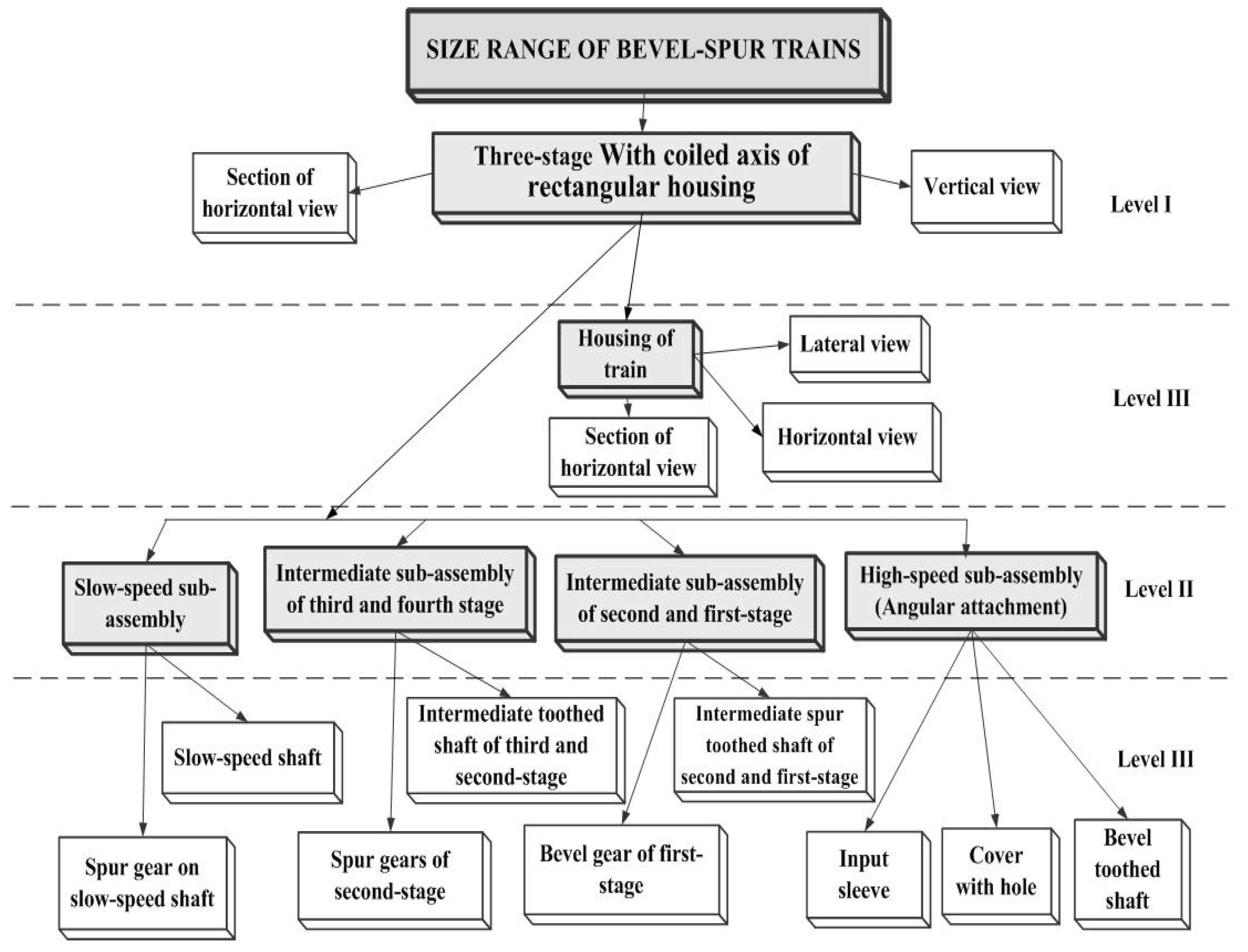
Hierarchic model is based on the concept of navigation from the records on the top of hierarchy to the secondary records. In the case of gears’ size ranges, system structure of construction family is the sum of constructional solutions which are the part of it. In this way it is possible to separate hierarchic structure of the construction forms. It consists of assemblies, sub-assemblies, toothed elements, shafts, normalized parts, etc. As an example of hierarchic model solution a three-stage bevel-spur gear size range was presented (
Figure 6). When forming constructional forms, assemblies, sub-assemblies and such elements as housings (bodies, input sleeves) shafts, geared wheels presented in proper view and sections were examined.
In dependences between the relations in the system structure hierarchy of the gear size range there are three levels of relation:
level 1 – assemblies shown as gear compounds in the form of vertical view and the section of horizontal view,
level 2 – including such sub-assemblies as slow-speed, intermediate of second and fist stage, high-speed and angular attachment,
level 3 – elements such as housings of the gear, shafts, bevel and spur geared wheels and the input sleeve together with the cover.
Also, the number of shafts and geared wheels is dependent on the number of gear stages. The elements appear as common, global for above-mentioned various kinds of gear size ranges. In vertical view the housing (which is used) is rectangular. It was presented in the form of vertical, horizontal and lateral view and sections. These are local elements for each type of gears. As practice showed the hierarchical model has significant drawbacks for the conceptual modelling. It especially hinders representing of semantic compound many-to-many and forces the artificial and redundant navigation by intermediate recording. However, it is often used unambiguously determining the levels of hierarchy in which the studied machine elements (e.g. assemblies, sub-assemblies and elements of gear size ranges) may be classified.
2.3.2. Entity-Relationship Model
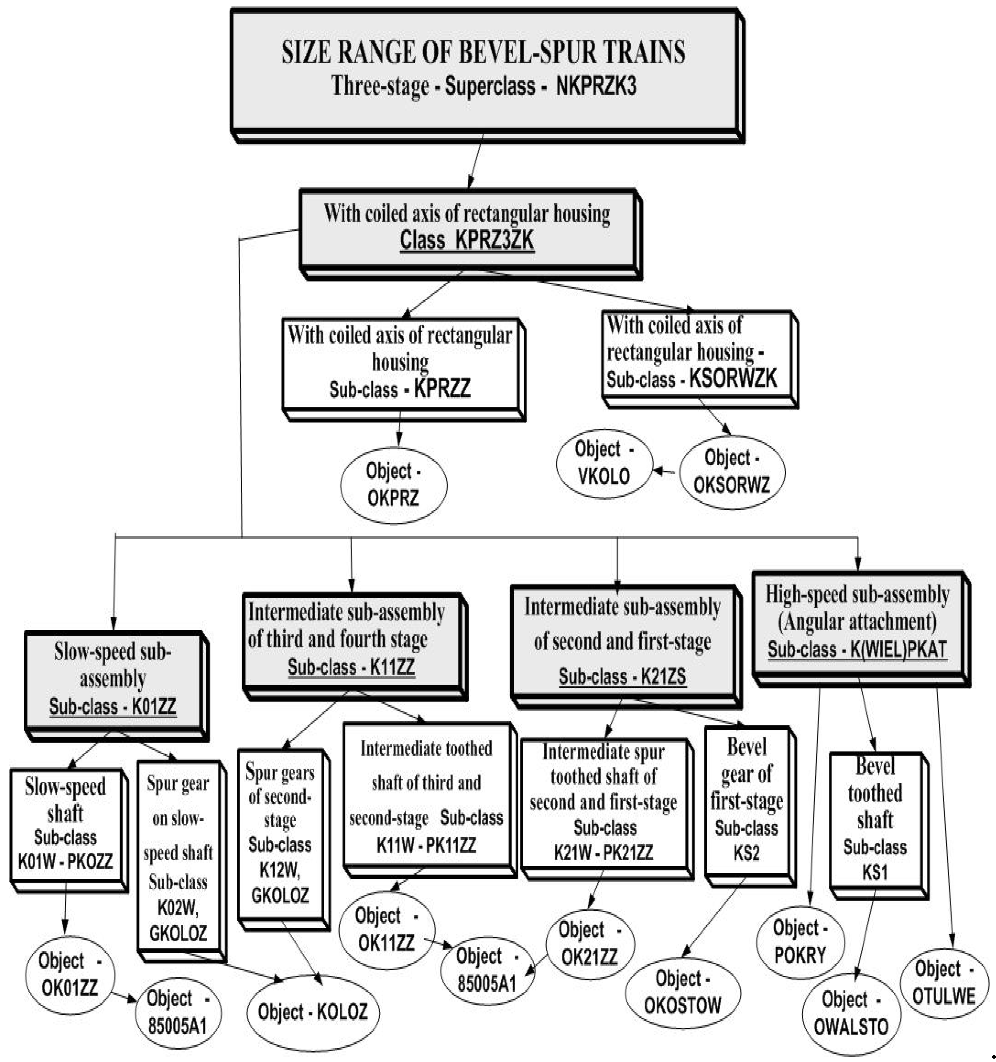
The next model used in object analysis is entity-relationship model (
Figure 7) which allows presenting objects and connections between them in the form of graph.
The model introduces such terms as:
entity – a group of objects having similar properties which may be and is worth to be distinguished in the modelled reality e.g. assemblies, sub-assemblies, shafts, wheels, etc,
relationship – group of connections between the entities e.g. shafts, wheels and norm elements (bearings, rings, etc.) making up sub-assemblies and together with the bodies, covers, bearings, etc. making up assemblies,
attribute – a characteristic of entity or relationship, e.g. assembly as size range of bevel and spur gears (two-, three-, four-stage), sub-assemblies; slow-speed, intermediate, high-speed, angular attachment, shafts, geared wheels (spur and bevel), etc,
generalization/specialization – inclusion of groups of objects e.g. the shaft and wheel are more general (specialized) entity than sub-assembly because the pinion or geared wheel for a specific sub-assembly may be bevel or cylindrical,
lot size – for a given entity, it is the definition of minimum and maximum number of objects of other entity which may be connected to one object of a previous entity within a framework of a given relationship. For example, a set of a three-stage bevel-spur gear consists of one slow-speed sub-assembly, two intermediate sub-assemblies and one high-speed sub-assembly,
identification (name) of classes, sub-classes and objects e.g. class of assembly with coiled axes in rectangular housing named KPRZ3ZK, sub-assembly of toothed cylindrical shaft named K02W, object of geometrical form of the shaft named OK01Z, etc.
2.3.3. Data-Flow Model
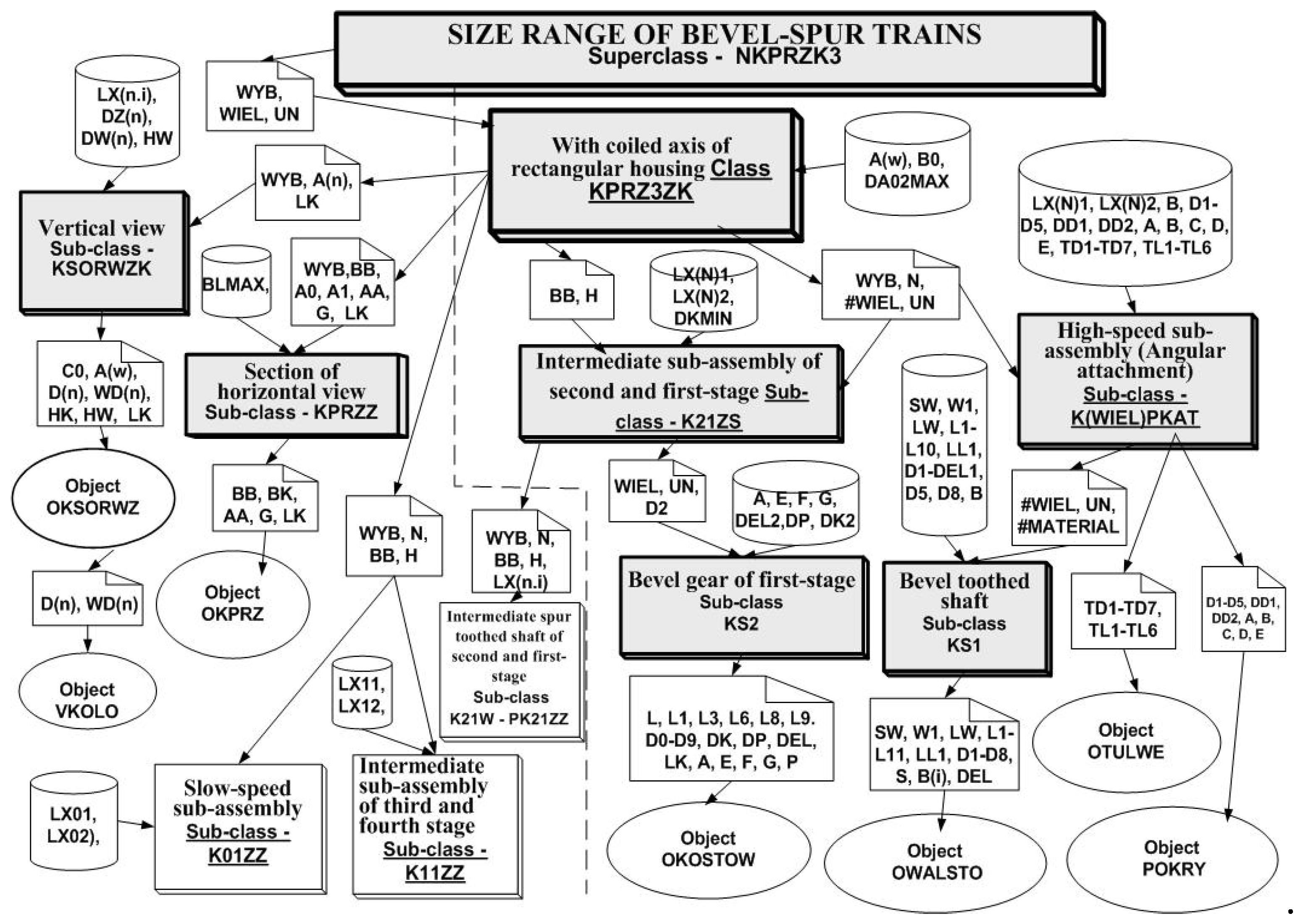
The data-flow model as the next used in object analysis shows the sets of system modules (classes, sub-classes and objects) pointing to which information flow between them, e.g. external attributes inherited from classes and sub-classes from data-bases. Events, states, activities and processes are represented here in the form of diagrams. It is a static model. The sequence of the activities or cause-result relationship between the activities are not crucial. The diagram of object-oriented shaping of constructional form of the size range units of a three-stage bevel-spur gear is presented as an example of the data-flow model application (
Figure 8).
The diagram consists of four kinds of designations:
processes which are classes, sub-classes, objects (marked graphically with rectangles or ovals),
interfaces as means of communication between the modules (shown in the diagram in the form of envelopes),
data-store which are the data-base (marked by cylinders),
arrows showing the data and information flow.
In methodology the models are based on diagrams showing relations between values:
introduced (input to the process) – these are data-bases (cylinders) of such attribute values as axes-distance, wheels and bodies width, bearings numbers, etc. and the relations derived from the classes of higher hierarchic level inherited by classes of lower hierarchic level, e.g. inner and outer length of the body, the thickness of the body wall, distance between axes, etc.,
processed (the process itself or sub-processes) characteristic for classes, sub-classes (rectangles) and objects (ovals) e.g. the class of gear unit – KPRZ3KZ, the sub-class of horizontal view of the body – KPRZZ and the object of horizontal view of the body – OKPRZ, etc.,
derived from classes as inheritance form (output of the processes) shown in the form of envelopes with outer attributes.
2.3.4. Object Model
The three models described earlier enabled, in an abstract way, making the analysis of the problem presented [
17,
18]. The problem concerned methodological formulation of object-oriented shaping of the constructional form of the gear’s size ranges. Thanks to those models entities were selected, relationships between them were defined and it was determined in which hierarchy they are modelled. Moreover, design processes in the form of classes, subclasses and objects were presented emphasising the information flowing between them.
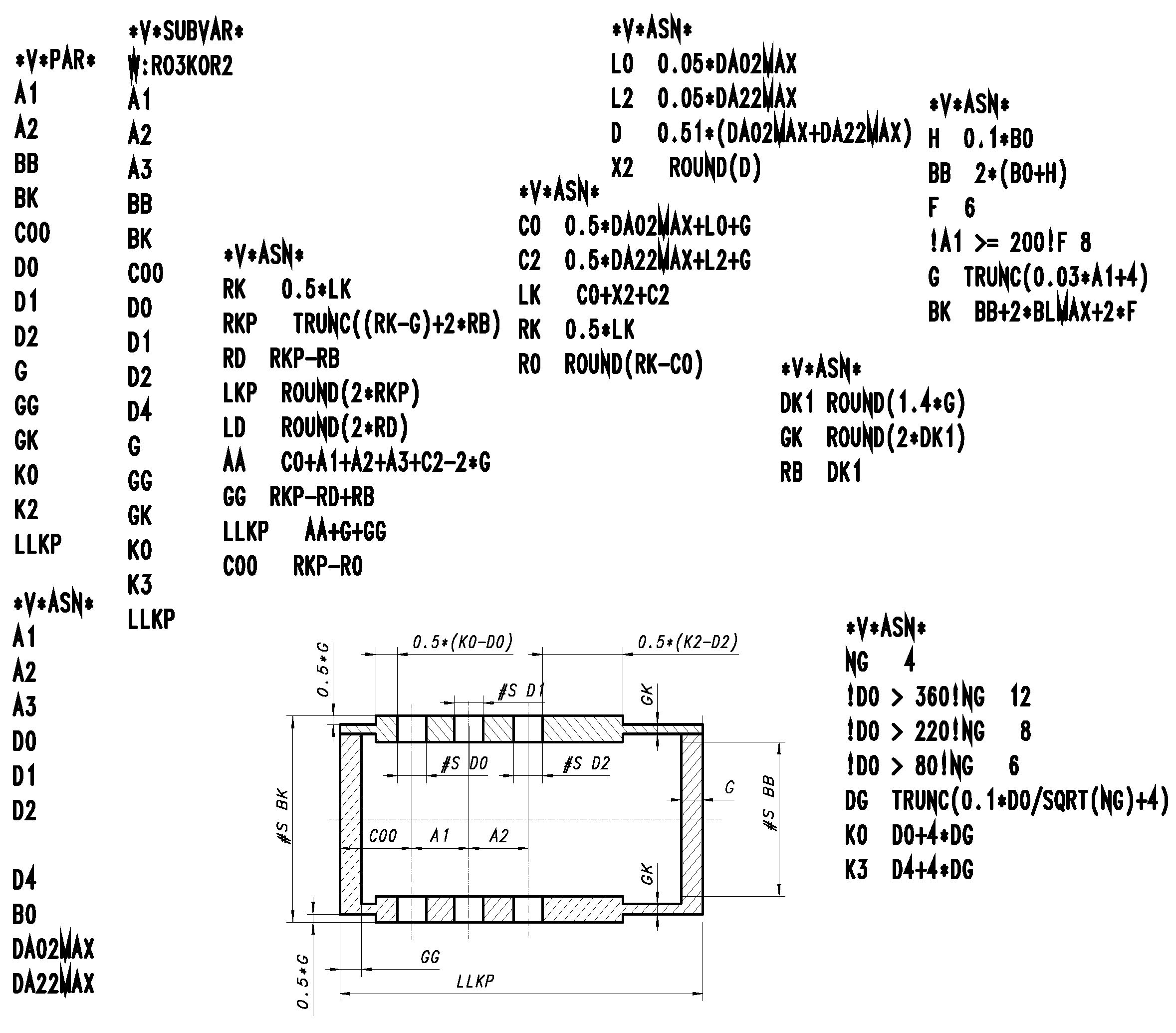
However, an object model is the one whose basis are the terms of class, object, abstraction, inheritance, making hermetic, polymorphism, dynamic bonding and other objectivity features (
Figure 9). The model concerns diagrams showing objects, their classes and relations between them. Diagrams are frequent representations of graphic interpretation of modelling. Model also introduces the terms of object codes and aggregation connections between the objects. Classes are linked by means of aggregation connections enabling navigation between the objects connected with them, modelling the whole to its part.
Models used in object design are functions, operations assigned to object classes and inherited by its subclasses and objects. They operate in a hermetic way in classes and subclasses having appropriate names using outer information and proceeding algorithms based on formula worked out earlier.
In the object model, from the conceptual point of view, the place of method storing is a suitable class. That means that such a method may be used for any object being its direct or indirect occurrence.
Object model usually concerns the diagram of class aggregation representing the whole-part relation between the objects. The diagram shows classes, subclasses of objects, attribute names, methods and relations between objects as well as forms of inheritance and numerousness of the relations.
As an example, the diagram of class aggregation of the train housing is presented (
Figure 9). The model consists of one class, two subclasses and three objects realizing in a graphic way the constructional form of the housing.
2.5. Conclusions
As mentioned above the analysis as theoretical consideration has the beginning in the designers mind. There is decomposition that is the “from general to details view” analysis of the designed assembly, e.g. the three-stage bevel-spur gear into sub-assemblies and elements and selecting super-classes, classes and subclasses. The subclasses are elements such as wheels, shafts, bodies, the classes are sub-assemblies e.g. slow-speed, intermediate, high-speed. The super-classes are kinds of assemblies e.g. three-stage bevel-spur gear trains.
Object programming as presented in chapter 2 (
Figure 3) as the development of object analysis is the process of defining the created construction components. It is realized by interaction of classes in a hierarchic way using the properties of object programming used in computer science. Classes and object communicate between each other by means of inheritance. Subclass may inherit attributes from one or a few super-classes.
After selecting classes and objects, where the diagram of hierarchic model was used in the object analysis, determining the relations between them by means of entity-relationship model and message-flow – data-flow model diagram, there follows working out of computer system in the form of object model with the possibility of forming and selecting variant (e.g. the shape of the body, axes position, etc.). Models made in this way being parameterized objects, and earlier prepared data-bases of calculated parameters allow creating object data-bases which are the input to object synthesis process as implementation of the methodology of object-oriented design of gears’ size ranges.
Summing up, one may conclude that object analysis that is creating classes, subclasses and objects, determining attributes and methods in particular classes, making diagrams of data-flow between the classes and subclasses, making models in phases, building databases is the introductory stage of the construction record according to suggested methodology of object-oriented design of gears size ranges.
Object analysis is almost all performed on the example of the basic gear. The properties of both object and the size range design enable significant accelerating of the design process of the ordered sets of size range units. As studies showed, the time needed for performing the analysis for the three-stage bevel-spur gear is about 16 hours and additionally (n-1) hours for generalizing the analysis for all derivative gears. Comparing the times needed for preparing constructional documentation, which is presented in details in the Part 2 of this article, concerning synthesis, according to conventional and suggested method, one may claim that the efficiency of object-oriented methodology of gear size ranges design increases with the increase in the number of trains making up the size range. Therefore, in case of the number units in the size range n=5, labour-consumption decreases to 60% and when n=8 to 70%.
However, the analysis itself demands large expenditure of work, just to prepare the object models, doing calculations or considerations and for individual projects is incomparable. It makes sense as a component of the whole creation process i.e. starting with analysis through synthesis to prototype studies ending in the assessment of the solution with appropriate conclusions [
16,
19,
20,
21,
23,
27]
Implementation of the object analysis to the whole design process influenced, as claimed earlier, shortening the time of design and therefore reduced the costs of preparing technical documentation as well as caused the existence of immeasurable application effects such as:
accumulation of knowledge in class methods which thanks to electronic storing is safer and may be still developed without the fear of personal changes,
single object analysis for the whole size range when in case of conventional method the record of each size construction must be done individually,
facilitating the control of the stages of design process by introducing one diagram for all sizes of size range,
preparing objects for module-segment design based on selection using advisory systems and artificial intelligence.
In spite of lots of advantages mentioned above, the drawback of the object analysis resulting from the properties of object programming is its arbitrariness. It is caused by the fact that once created classes and objects are difficult to modify and interference in methods may cause dimension collisions. Moreover, the variety of tasks connected with shaping the constructional form of gear size ranges does not allow for design of the logic of programs in such a flexible way so that the whole process could be done without the human intervention. It is caused by the lack of software for full automation of the design process.
