Submitted:
13 May 2024
Posted:
14 May 2024
You are already at the latest version
Abstract
Keywords:
1. Introduction
2. Quantum Search Algorithm

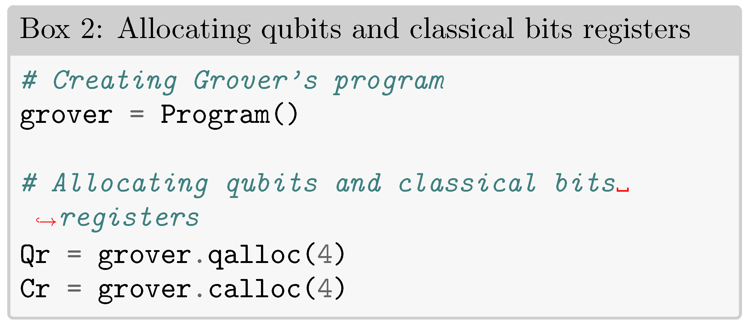
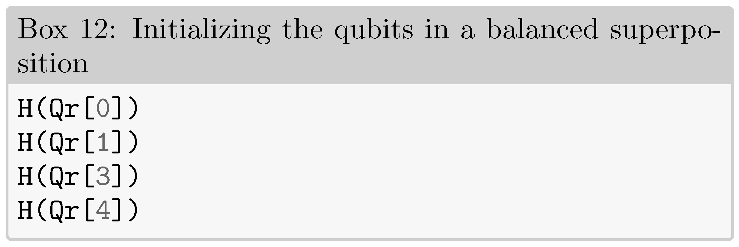
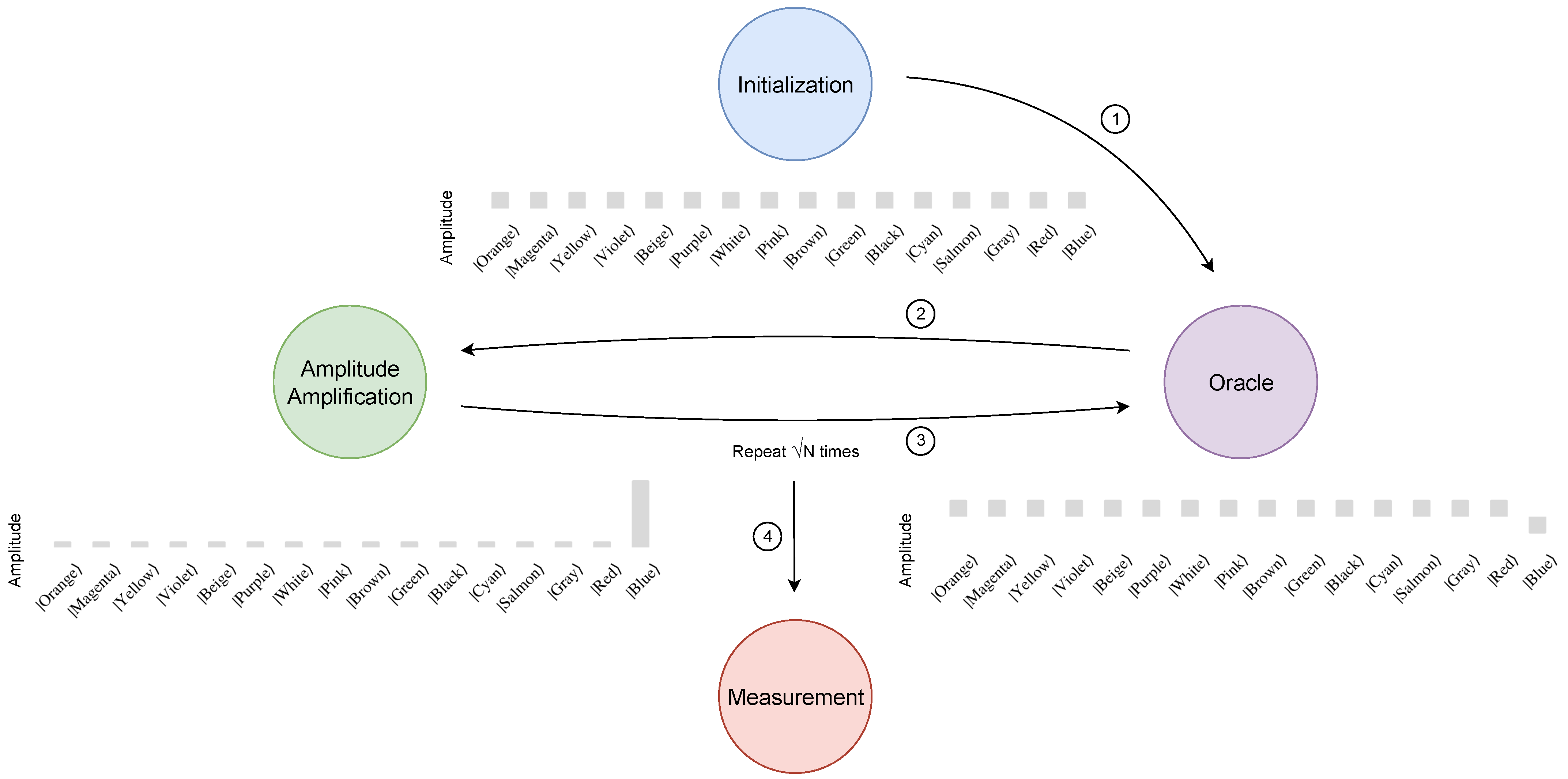
2.1. Initialization

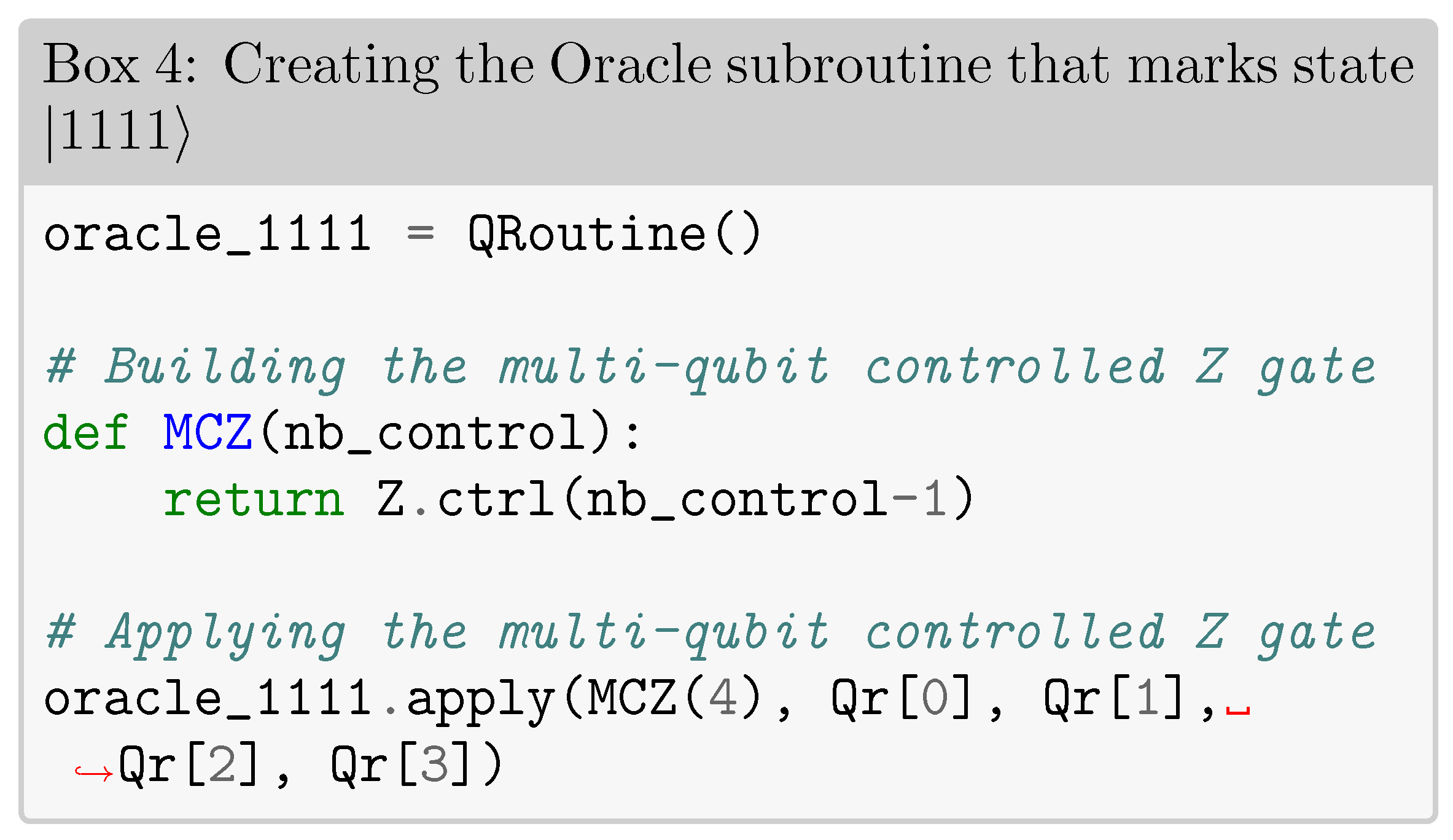
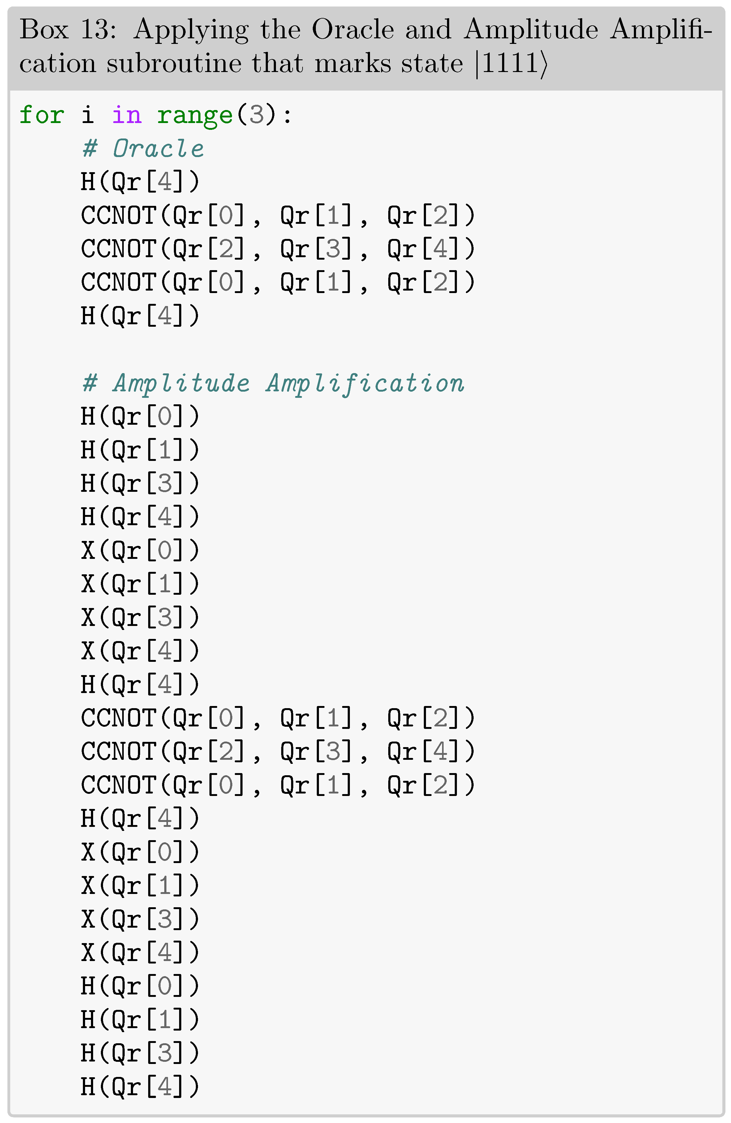
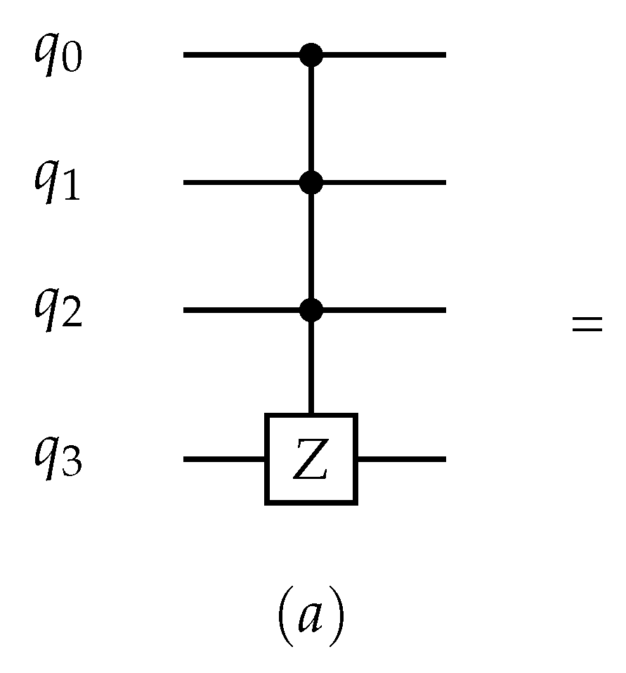
2.2. Oracle
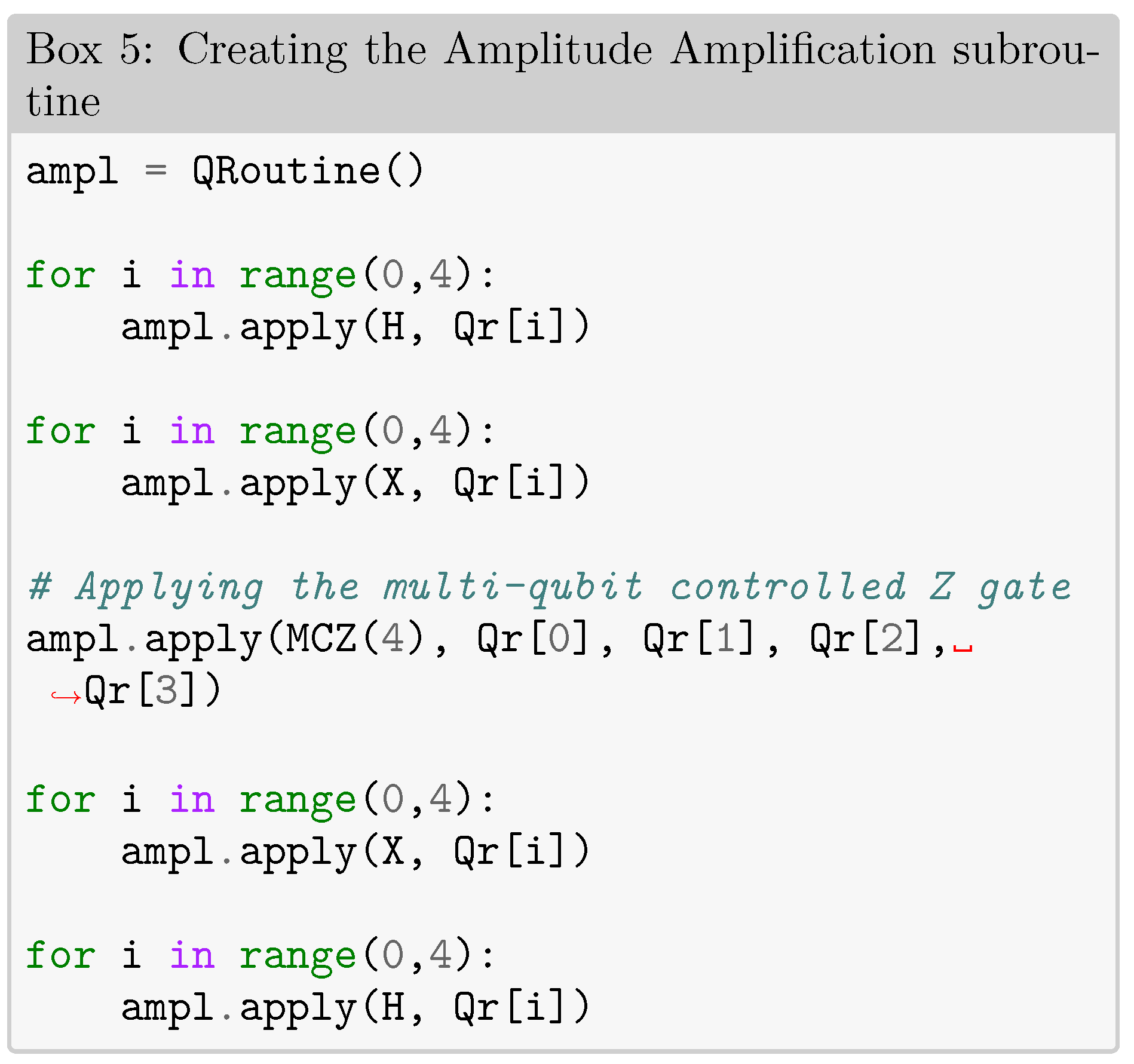
2.3. Amplitude Amplification
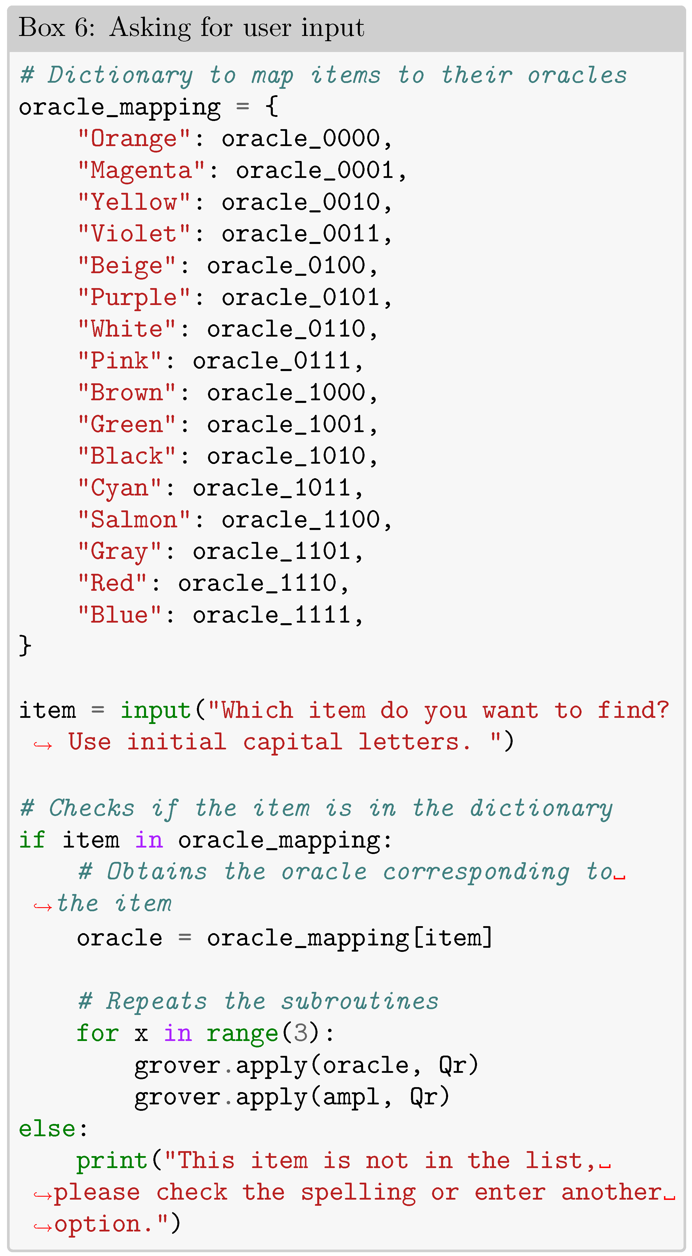
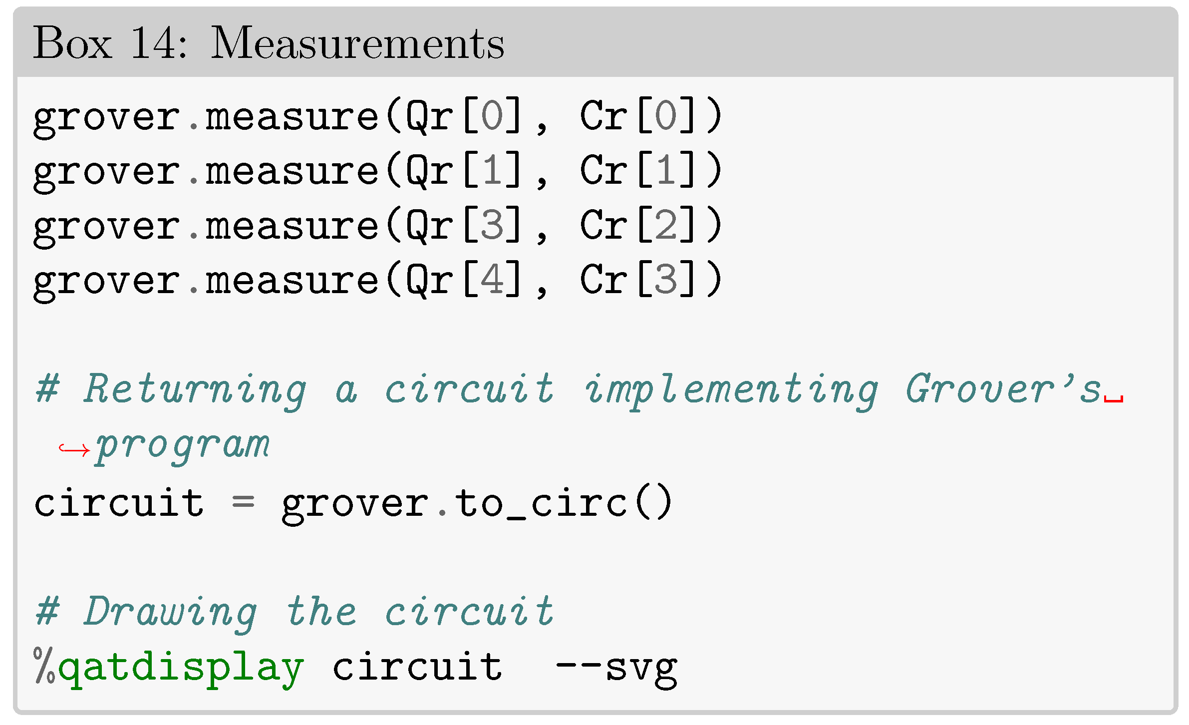
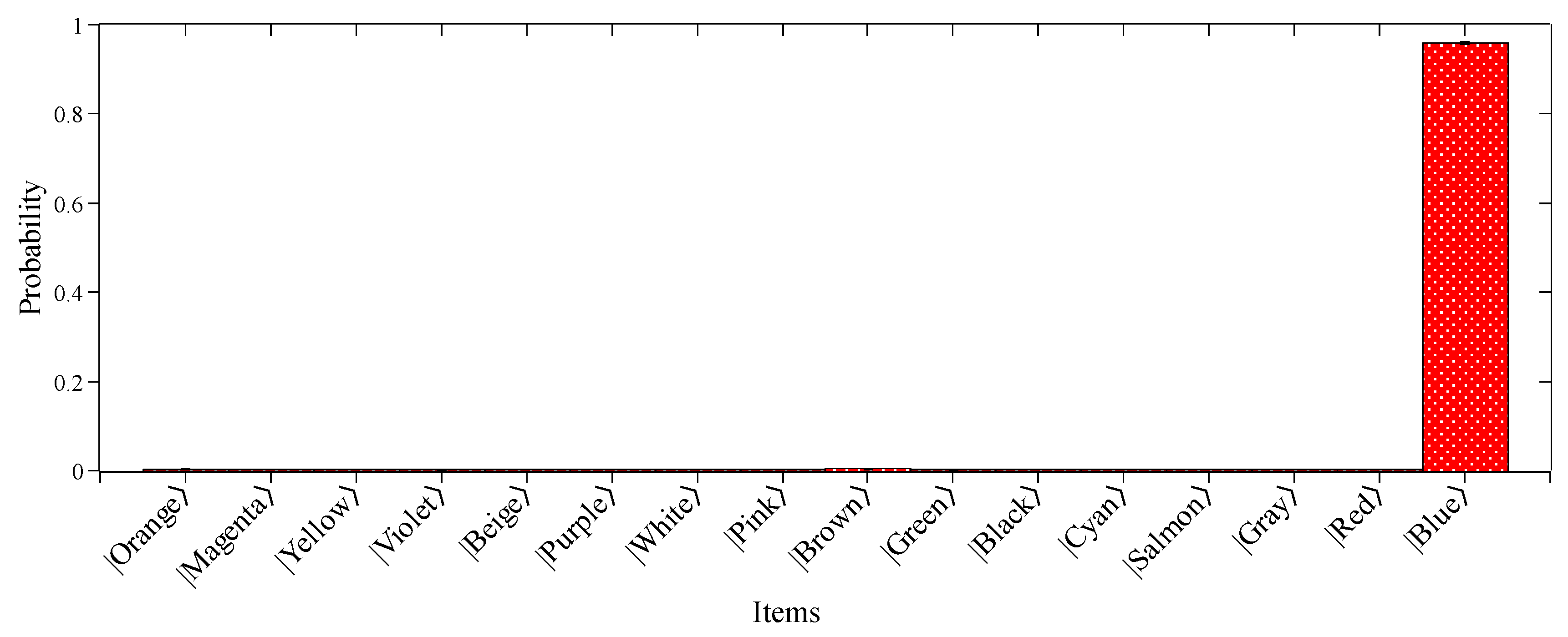
2.4. Measurement
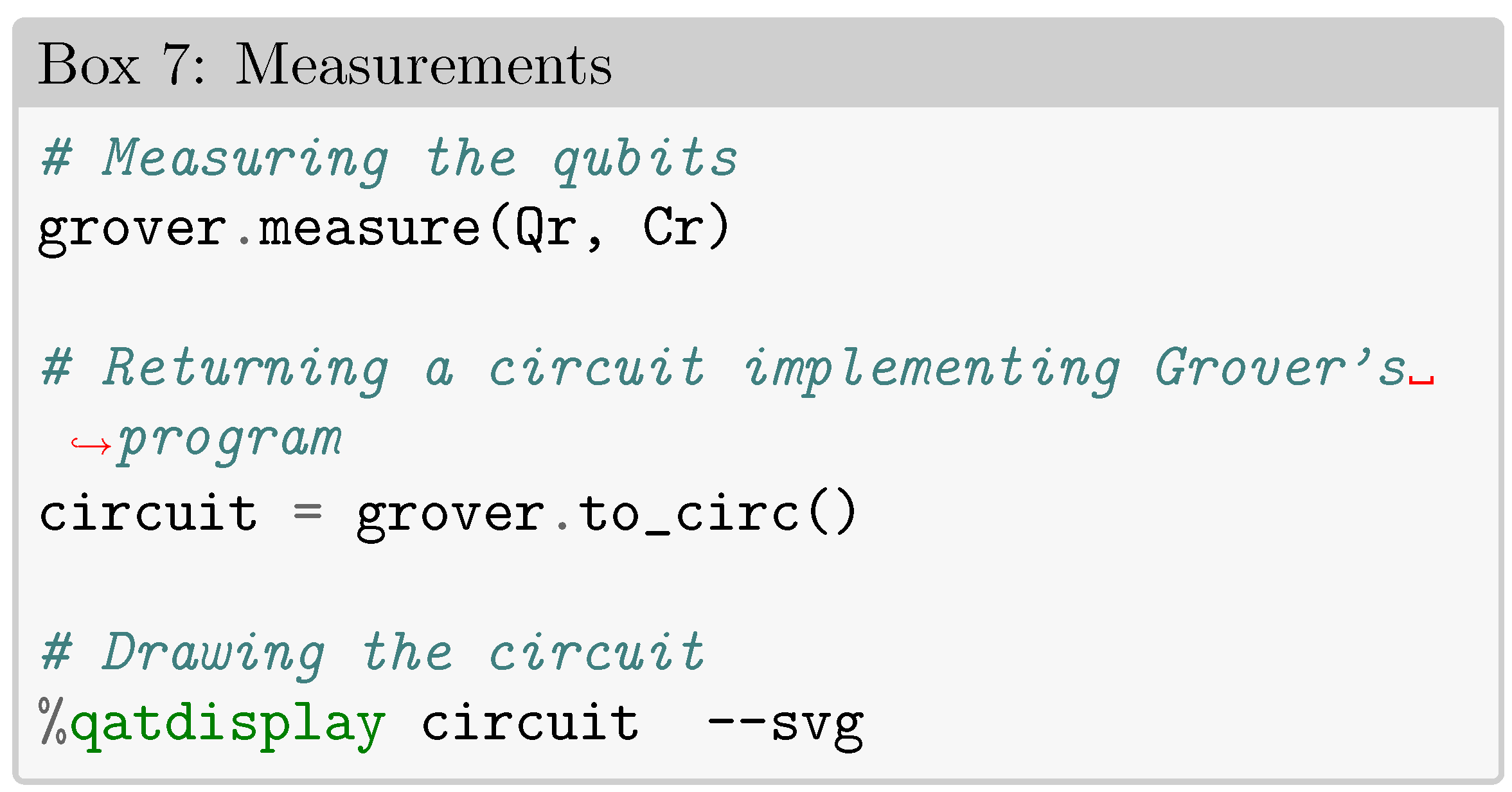
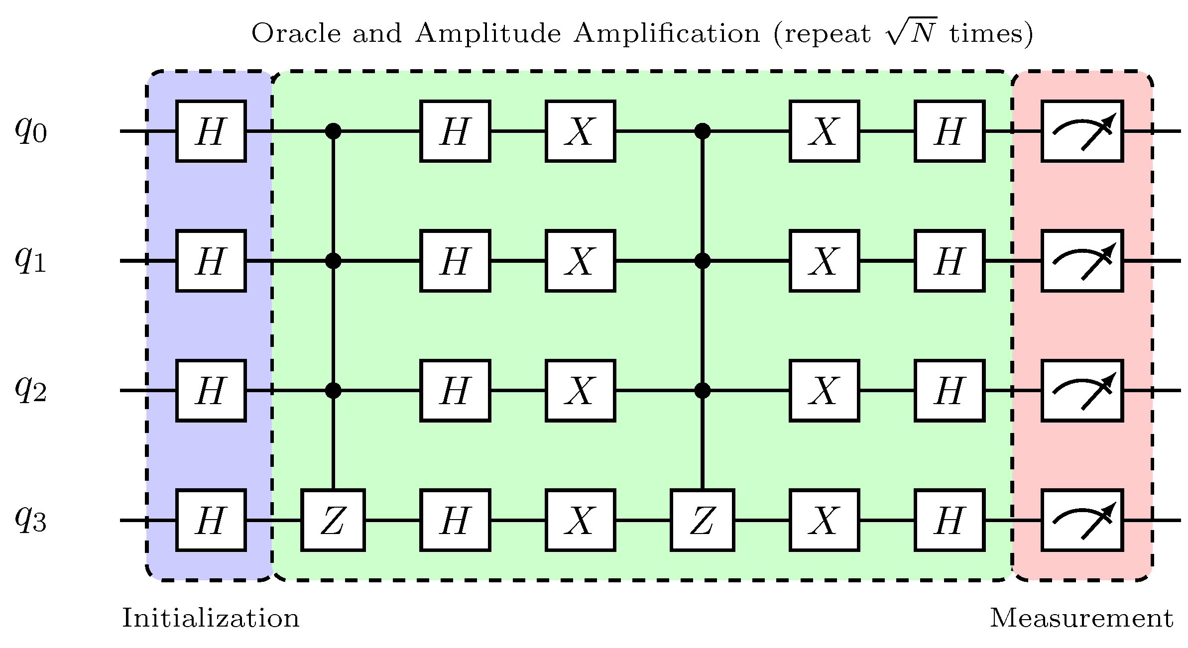
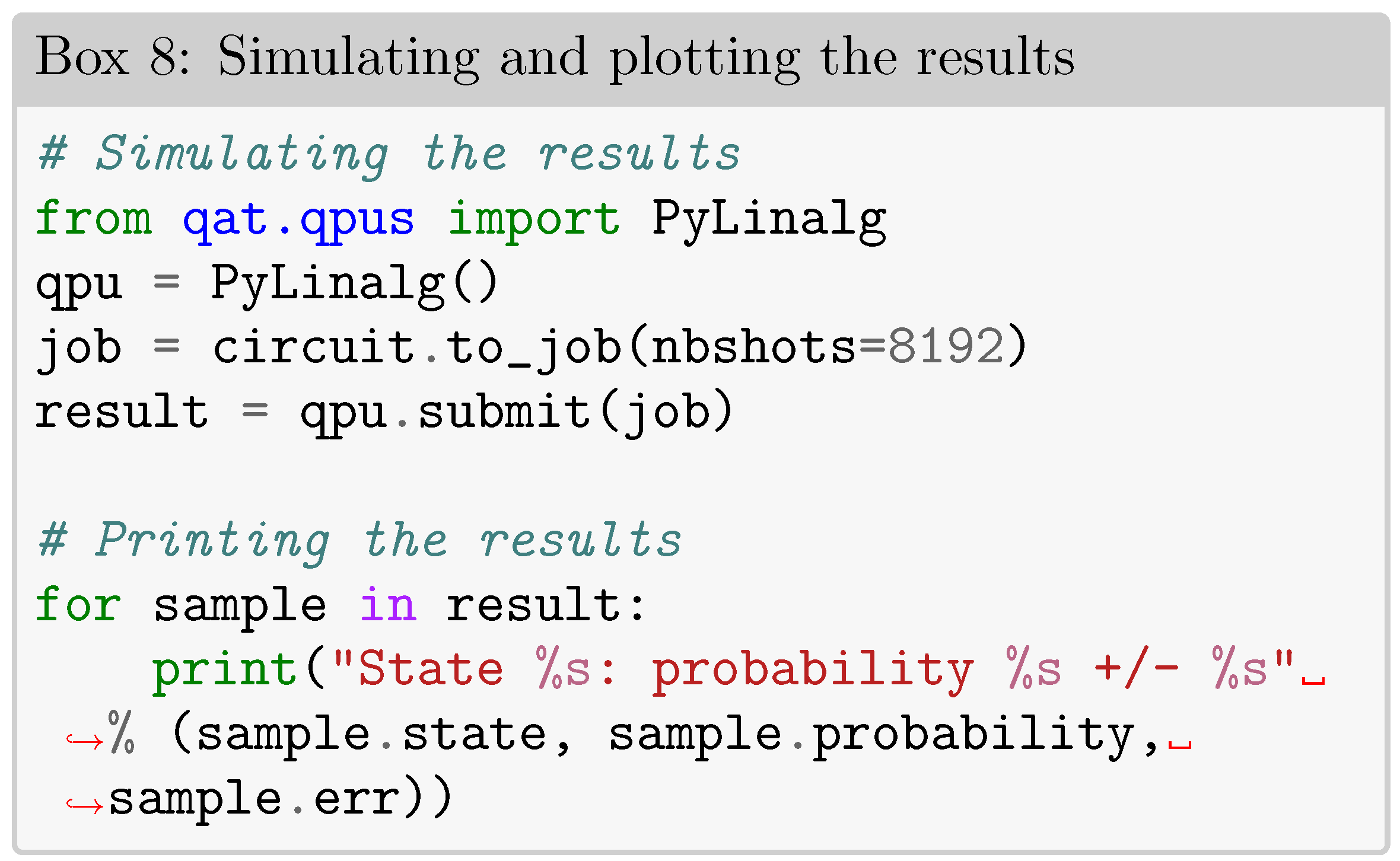
3. Quantum Noise Interference on Grover’s Algorithm
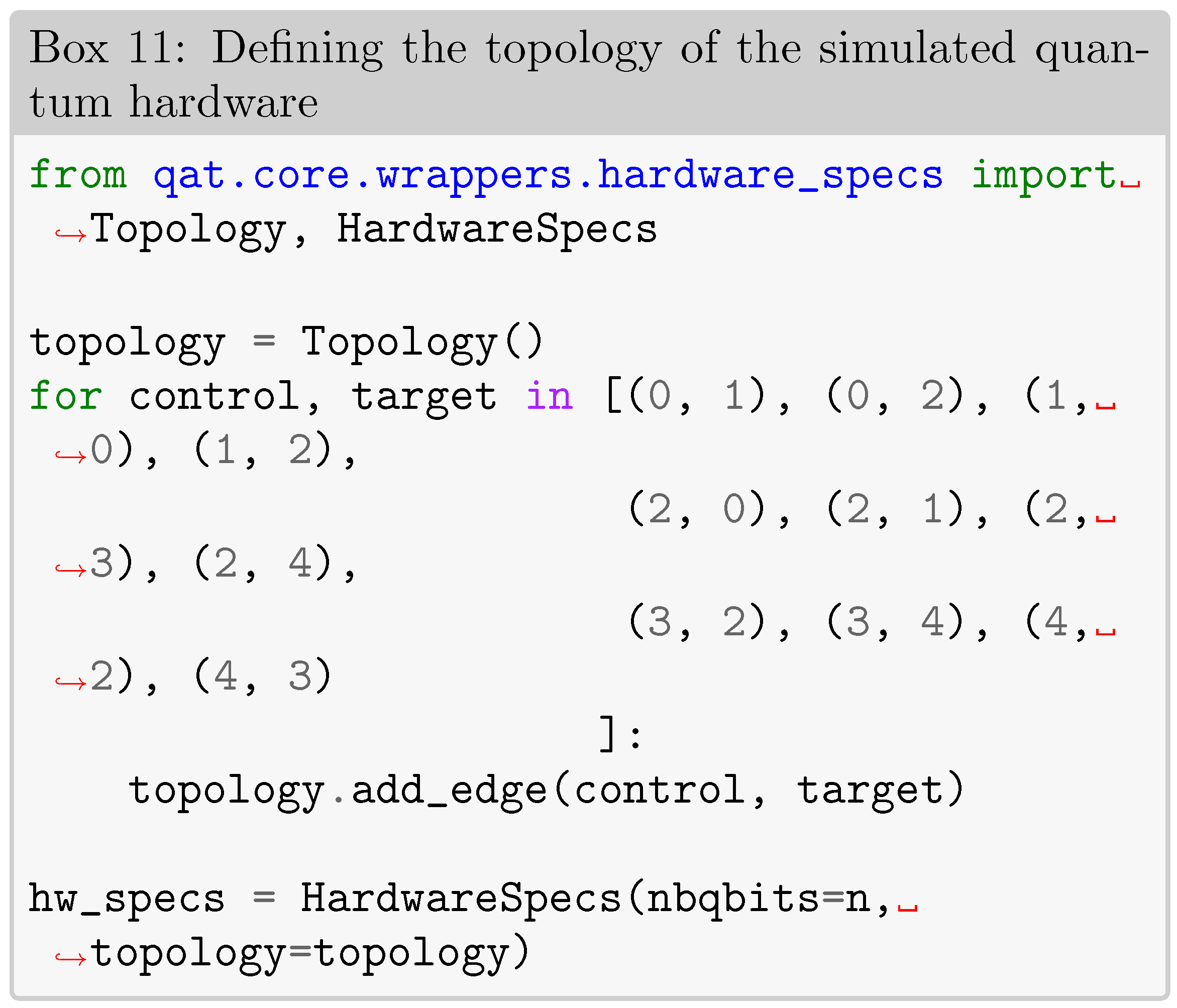
3.1. Quantum Hardware Model Simulation

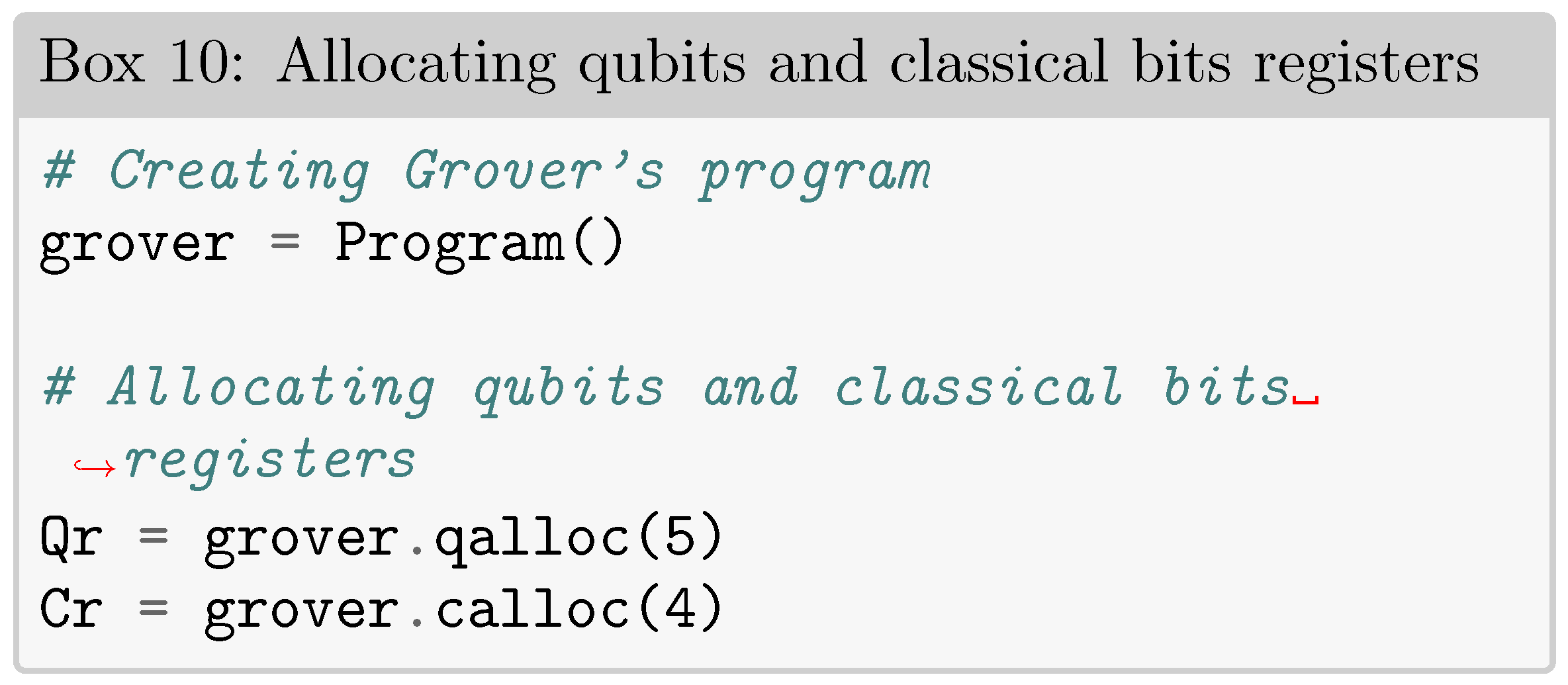
3.2. Quantum Noise
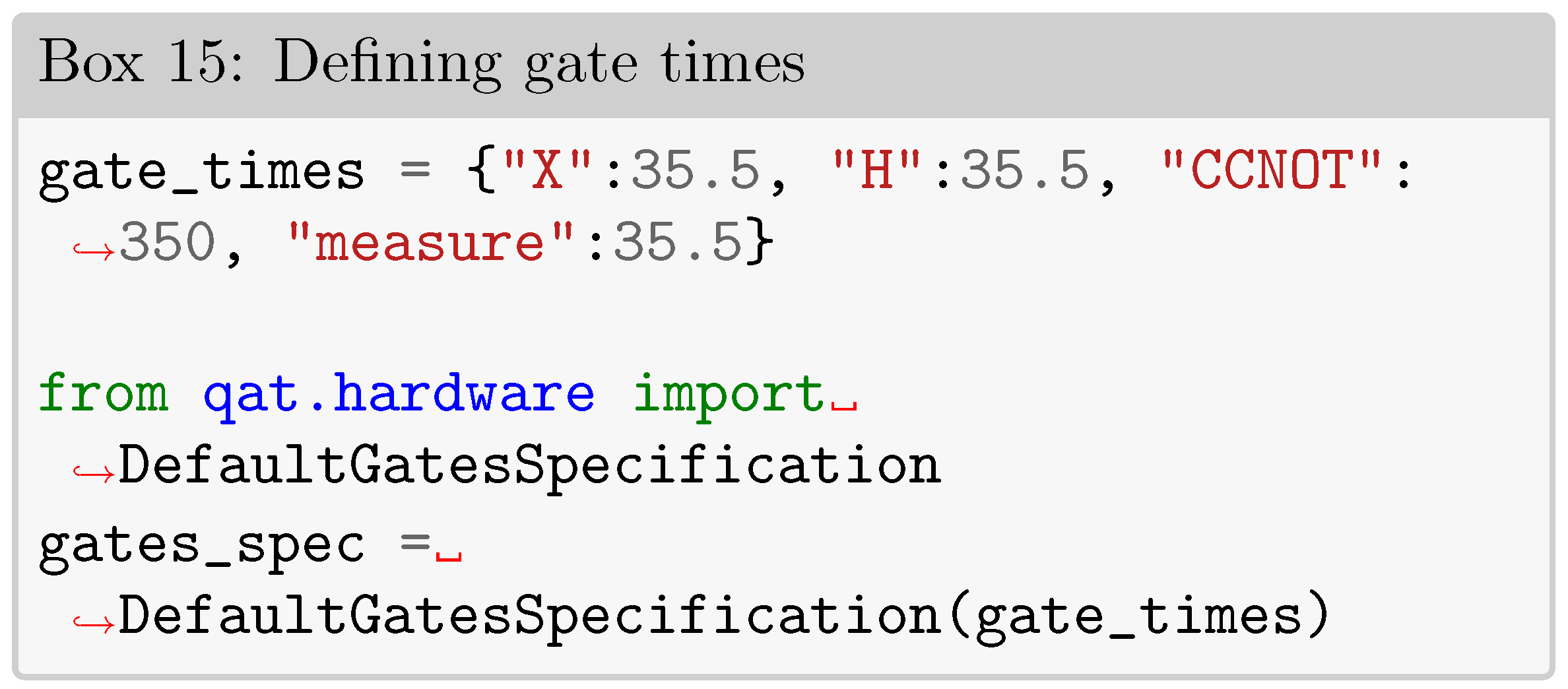
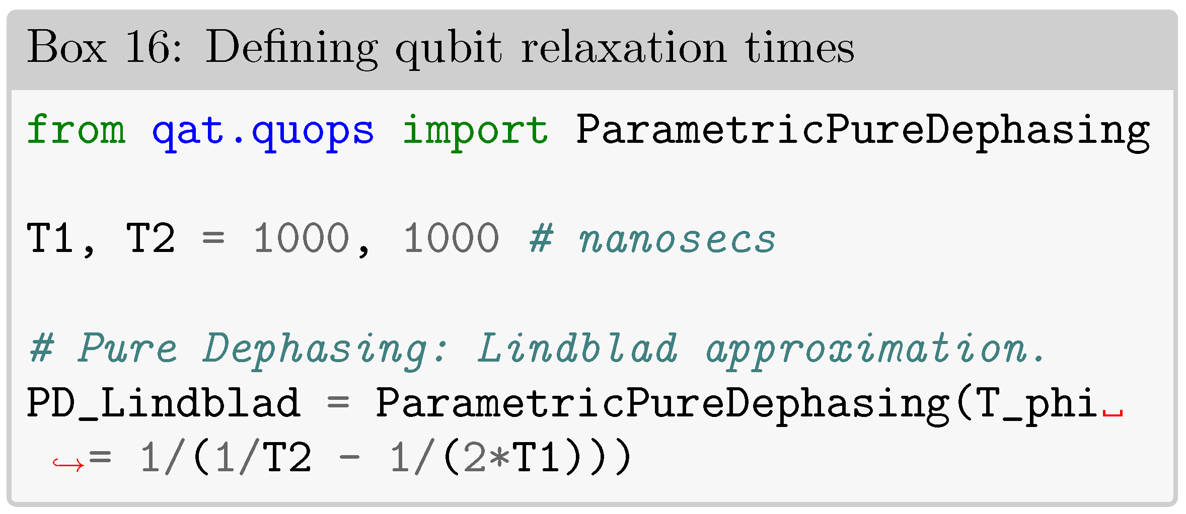
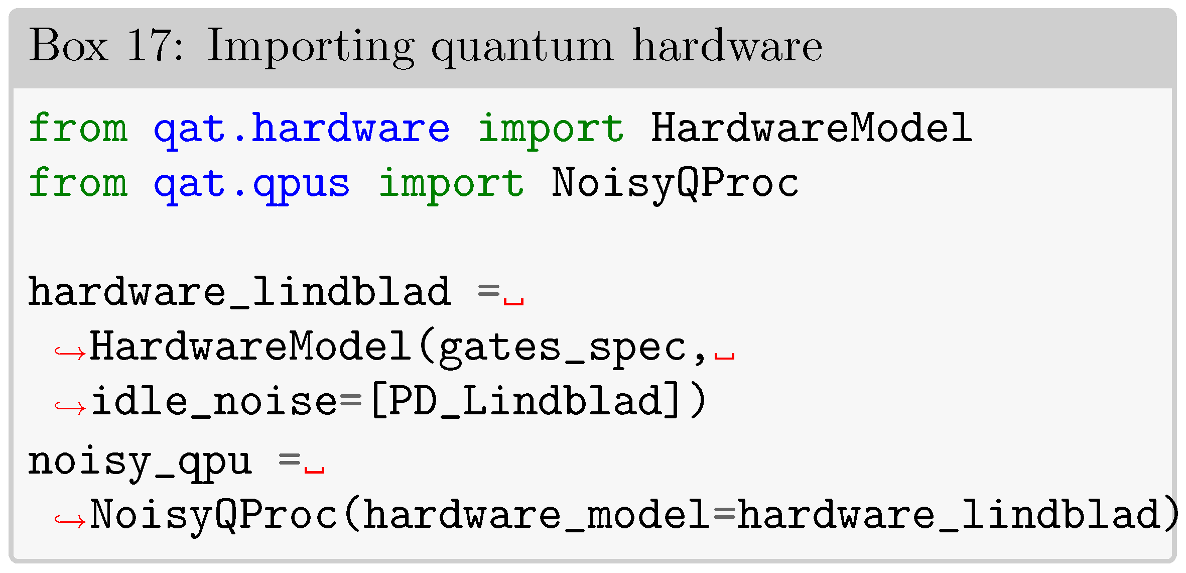
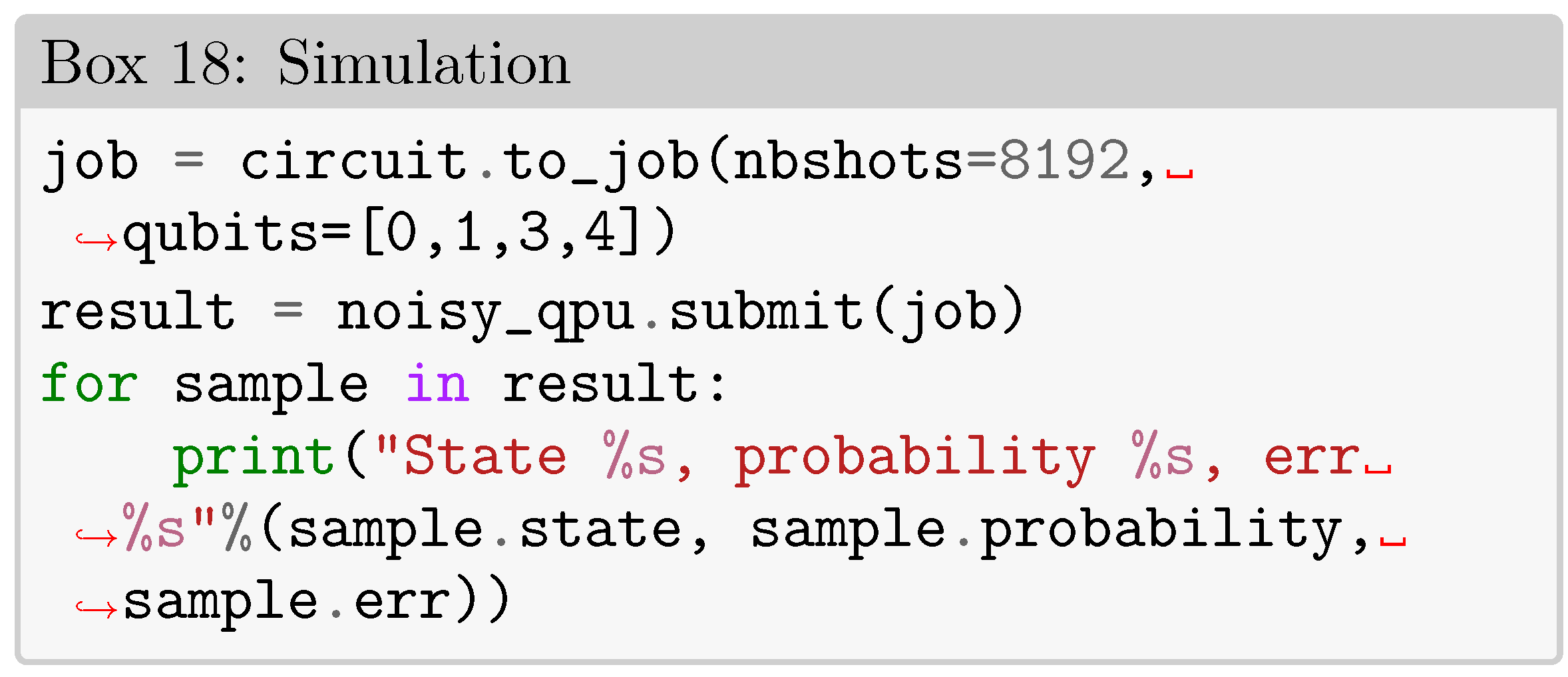
4. Conclusion
Data Availability Statement
Acknowledgments
Conflicts of Interest
References
- Ivan H. Deutsch. Harnessing the power of the second quantum revolution. PRX Quantum, 1:020101, Nov 2020. [CrossRef]
- Matteo Atzori and Roberta Sessoli. The second quantum revolution: Role and challenges of molecular chemistry. Journal of the American Chemical Society, 141(29):11339–11352, 2019. [CrossRef]
- Barbara M Terhal. Quantum supremacy, here we come. Nature Physics, 14(6):530–531, 2018. [CrossRef]
- Aram W Harrow and Ashley Montanaro. Quantum computational supremacy. Nature, 549(7671):203–209, 2017. [CrossRef]
- Elizabeth Gibney. The quantum gold rush. Nature, 574(7776):22–24, 2019.
- Guido Peterssen. Quantum technology impact: The necessary workforce for developing quantum software. In QANSWER, pages 6–22, 2020.
- Xinbiao Wang, Yuxuan Du, Yong Luo, and Dacheng Tao. Towards understanding the power of quantum kernels in the nisq era. Quantum, 5:531, 2021. [CrossRef]
- John Preskill. Quantum computing in the nisq era and beyond. Quantum, 2:79, 2018.
- Yasunari Suzuki, Suguru Endo, Keisuke Fujii, and Yuuki Tokunaga. Quantum error mitigation as a universal error reduction technique: Applications from the nisq to the fault-tolerant quantum computing eras. PRX Quantum, 3:010345, Mar 2022. [CrossRef]
- M. AbuGhanem and Hichem Eleuch. Nisq computers: A path to quantum supremacy. ArXiv, abs/2310.01431, 2023. [CrossRef]
- J. A. Montanez-Barrera, M. V. von Spakovsky, Cesar E. Damian Ascencio, and S. Cano-Andrade. Decoherence predictions in a superconducting quantum processor using the steepest-entropy-ascent quantum thermodynamics framework. Physical Review A, 2022.
- S. Dasgupta and T. Humble. Reliability of noisy quantum computing devices. ArXiv, abs/2307.06833, 2023.
- https://myqlm.github.io/02_user_guide/01_write/01_digital_circuit/05_aqasm.html. Accessed: 09/04/2024.
- https://atos.net/en/2017/press-release/general-press-releases_2017_07_04/atos-launches-highest-performing-quantum-simulator-world. Accessed: 07/04/2022.
- https://atos.net/en/lp/myqlm. Accessed: 09/04/2024.
- https://atos.net/en/2019/press-release_2019_05_16/atos-launches-myqlm-to-democratize-quantum-programming-for-researchers-students-and-developers-worldwide. Accessed: 07/04/2022.
- https://atos.net/en/solutions/quantum-learning-machine. Accessed: 09/04/2024.
- https://github.com/maheloisaf/Supplementary-Information-Grover-Paper/tree/main. Accessed: 07/04/2022.
- Gleydson Fernandes de Jesus, Maria Heloísa Fraga da Silva, Teonas Gonçalves Dourado Netto, Lucas Queiroz Galvão, Frankle Gabriel de Oliveira Souza, and Clebson Cruz. Quantum computing: an undergraduate approach using qiskit. Revista Brasileira de Ensino de Física, 43:e20210033, 2021. [CrossRef]
- https://www.anaconda.com/download#downloads. Accessed: 09/04/2024.
- https://docs.jupyter.org/en/latest/. Accessed: 09/04/2024.
- https://myqlm.github.io/01_getting_started/%3Amyqlm%3A01_install.html. Accessed: 09/04/2024.
- https://myqlm.github.io/02_user_guide/01_write/01_digital_circuit/05_aqasm.html. Accessed: 09/04/2024.
- Michael A Nielsen and Isaac Chuang. Quantum computation and quantum information, 2002.
- Caroline Figgatt, Dmitri Maslov, Kevin A Landsman, Norbert M Linke, Shantanu Debnath, and Christofer Monroe. Complete 3-qubit grover search on a programmable quantum computer. Nature communications, 8(1):1–9, 2017. [CrossRef]
- Jairo Ernesto Castillo, Yesenia Sierra, and Nelson L Cubillos. Classical simulation of grovers quantum algorithm. Revista Brasileira de Ensino de Física, 42, 2019. [CrossRef]
- https://www.senaicimatec.com.br/. Accessed: 09/04/2024.
- IBM Quantum Experience https://quantum-computing.ibm.com. [Accessed: 11-November-2021].
- Barbara M Terhal. Quantum error correction for quantum memories. Reviews of Modern Physics, 87(2):307, 2015. [CrossRef]
- Aashish A Clerk, Michel H Devoret, Steven M Girvin, Florian Marquardt, and Robert J Schoelkopf. Introduction to quantum noise, measurement, and amplification. Reviews of Modern Physics, 82(2):1155, 2010. [CrossRef]
- Rahaf Youssef. Measuring and simulating t1 and t2 for qubits. Technical report, Fermi National Accelerator Lab.(FNAL), Batavia, IL (United States), 2020.
- Brian Rost, Barbara Jones, Mariya Vyushkova, Aaila Ali, Charlotte Cullip, Alexander Vyushkov, and Jarek Nabrzyski. Simulation of thermal relaxation in spin chemistry systems on a quantum computer using inherent qubit decoherence. arXiv preprint arXiv:2001.00794, 2020. [CrossRef]
- C. Lü, J.L. Cheng, M.W. Wu, and I.C. da Cunha Lima. Spin relaxation time, spin dephasing time and ensemble spin dephasing time in n-type GaAs quantum wells. Physics Letters A, 365(5-6):501–504, jun 2007. [CrossRef]
- JL Skinner and D Hsu. Pure dephasing of a two-level system. The Journal of Physical Chemistry, 90(21):4931–4938, 1986. [CrossRef]
- E Ferraro, M Fanciulli, and M De Michielis. Phonon-induced relaxation and decoherence times of the hybrid qubit in silicon quantum dots. Physical Review B, 100(3):035310, 2019. [CrossRef]
- Angela Dudley, Michael Nock, Thomas Konrad, Filippus S. Roux, and Andrew Forbes. Amplitude damping of laguerre-gaussian modes. Opt. Express, 18(22):22789–22795, Oct 2010. [CrossRef]
| ITEM | DECIMAL | BINARY | VECTOR |
|---|---|---|---|
| Orange | 0 | 0000 | |
| Magenta | 1 | 0001 | |
| Yellow | 2 | 0010 | |
| Violet | 3 | 0011 | |
| Beige | 4 | 0100 | |
| Purple | 5 | 0101 | |
| White | 6 | 0110 | |
| Pink | 7 | 0111 | |
| Brown | 8 | 1000 | |
| Green | 9 | 1001 | |
| Black | 10 | 1010 | |
| Cyan | 11 | 1011 | |
| Salmon | 12 | 1100 | |
| Gray | 13 | 1101 | |
| Red | 14 | 1110 | |
| Blue | 15 | 1111 |
| STATE | ORACLE | STATE | ORACLE | STATE | ORACLE | STATE | ORACLE |
|---|---|---|---|---|---|---|---|
 |
 |
 |
 |
||||
 |
 |

|
 |
||||
 |
 |
 |
 |
||||
 |
 |
 |
 |
Disclaimer/Publisher’s Note: The statements, opinions and data contained in all publications are solely those of the individual author(s) and contributor(s) and not of MDPI and/or the editor(s). MDPI and/or the editor(s) disclaim responsibility for any injury to people or property resulting from any ideas, methods, instructions or products referred to in the content. |
© 2024 by the authors. Licensee MDPI, Basel, Switzerland. This article is an open access article distributed under the terms and conditions of the Creative Commons Attribution (CC BY) license (http://creativecommons.org/licenses/by/4.0/).


