I. Introduction
The inverted pendulum on a cart is one of the most pedagogical systems in modern control theory, consisting of a freely pivoted rod mounted on a motor-driven cart. Because the inverted pendulum is inherently nonlinear and underactuated, swinging up and stabilizing the pendulum in its unstable upright equilibrium configuration while controlling the position of the cart is a nontrivial task that is widely used to demonstrate applications of a wide range of nonlinear and linear control theories.
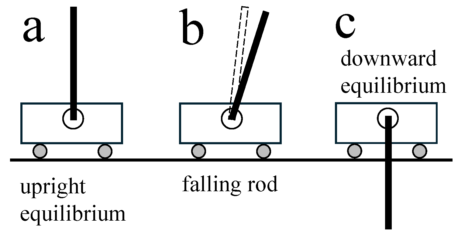
If the rod is directly above the motionless cart as shown in
Figure 1a, the rod can, in principle, stay upright indefinitely but in reality, it never does. The slightest disturbance that shifts the rod away from its upright equilibrium configuration as shown in
Figure 1b results in forces in the system that push the rod farther from the unstable upright configuration. In the absence of external forces, the rod will remain at rest hanging down in the downward equilibrium configuration as shown in
Figure 1c which is intuitively a stable equilibrium.
The system is non-feedback linearizable [
1] and loses controllability when the pendulum swings past the horizontal, making it especially difficult to perform controlled maneuvers. For instance, no continuous force globally stabilizes the pendulum in the upright configuration without displacing the cart [
2]. Although linear quadratic regulators (LQRs) can be used as a robust [
3] and quick controller for local stabilization at the unstable equilibrium [
4], linear-based controllers have a very small domain of attraction [
3,
4], typically effective only when the pendulum is within
of the upright configuration and the angular speed of the pendulum is within
. In this paper, the energy control method based on multiple Lyapunov functions proposed in [
5] will be implemented and evaluated against the conventional swing-up controller based on a single Lyapunov function that is traditionally used [
6,
7,
8]. This paper will also compare the performance of an LQR controller which known for its fast settling times, in stabilizing the pendulum close to the upright equilibrium configuration against the sliding mode controller (SMC) which is also based on a Lyapunov function and is known for its robustness to external and internal disturbances and to model uncertainties [
9].
Section II presents the dynamic model of the inverted pendulum on a cart.
Section III presents the energy control method based on multiple Lyapunov functions that is used in this paper and the traditional energy control method of the inverted pendulum based on a single Lyapunov function.
Section IV discusses the use of LQR and pole placement to quickly stabilize the system prior to swing-up to force global stability and after swing-up to guarantee fast and smooth stabilization with less oscillation [
3]. The performance of the LQR controller is compared with that of a sliding mode controller which is well known for its robustness to system disturbances and model uncertainties.
Section V compares the performance of the swing-up controllers presented in
Section III.
Section VI discusses various intermediate controllers and techniques that can be used to improve stability or increase swing-up and stabilization speed when implementing the nonlinear swing-up and linear stabilization controllers discussed herein.
Section VII summarizes the controller ideas and findings of the paper.
II. Dynamic Model
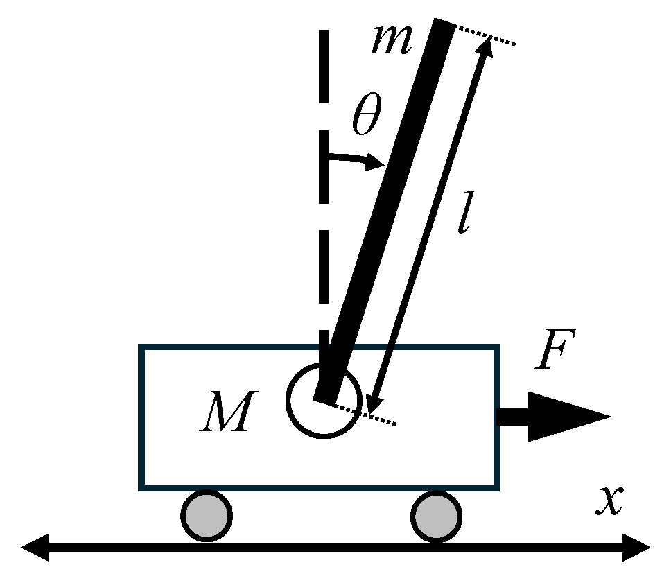
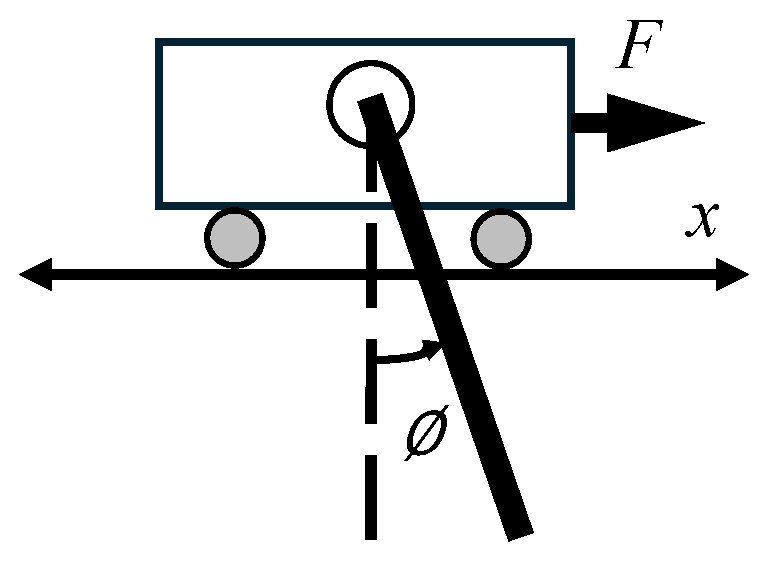
In the inverted pendulum system, we attempt to control the rod angle
and cart position
x for a given rod of mass
m and length
l mounted on a cart of mass
M that can freely move along the
x-axis as illustrated in
Figure 2. The aim of our control law is to drive
,
,
x, and
to 0 in a finite amount of time by varying the applied force
F on the cart. The rest of the system parameters are listed in
Table 1. The cart viscous friction, rod joint moment of inertia, and rod moment of inertia are neglected since they are very small compared with the other quantities in our system.
The dynamic equations of motion for the inverted pendulum on a cart can be derived using the Euler-Lagrange equations [
5,
10]:
The trigonometric functions in (
1) and (
2) make the inverted pendulum system inherently nonlinear. Using (
1) and (
2), an equation for
and
in terms of the state variables
,
,
x, and
can be derived:
III. Swing-Up
For the swing-up controller, we want to find a Lyapunov function for
excluding
x so that the controller can focus on swinging the rod up instead of bringing the cart to
. The mechanical energy of the inverted pendulum without considering the kinetic energy of the cart is
When the pendulum is in the downward equilibrium configuration
,
. When the pendulum is in the upward equilibrium configuration
,
. Thus, to swing to the upward configuration,
E must increase to 0. Consider the Lyapunov function
which decreases to 0 as
E increases to 0 and
for
. A control input that forces
will ensure that
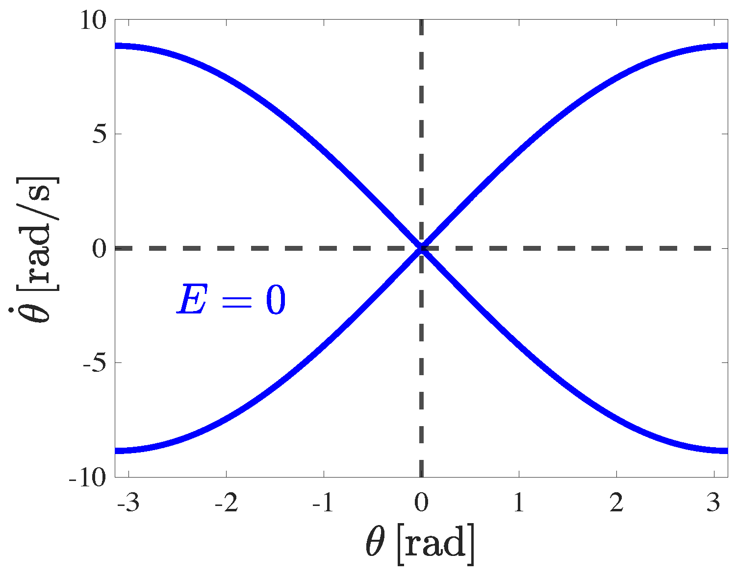
E decreases to 0. However, there are infinitely many values of
that make
as shown in
Figure 3. Thus, although
is a Lyapunov function for
E, it is not a Lyapunov function for
.
A modified Lyapunov function that is zero whenever
and
otherwise is proposed in [
5]:
whenever
which can be achieved (
) through the control input [
5]
where
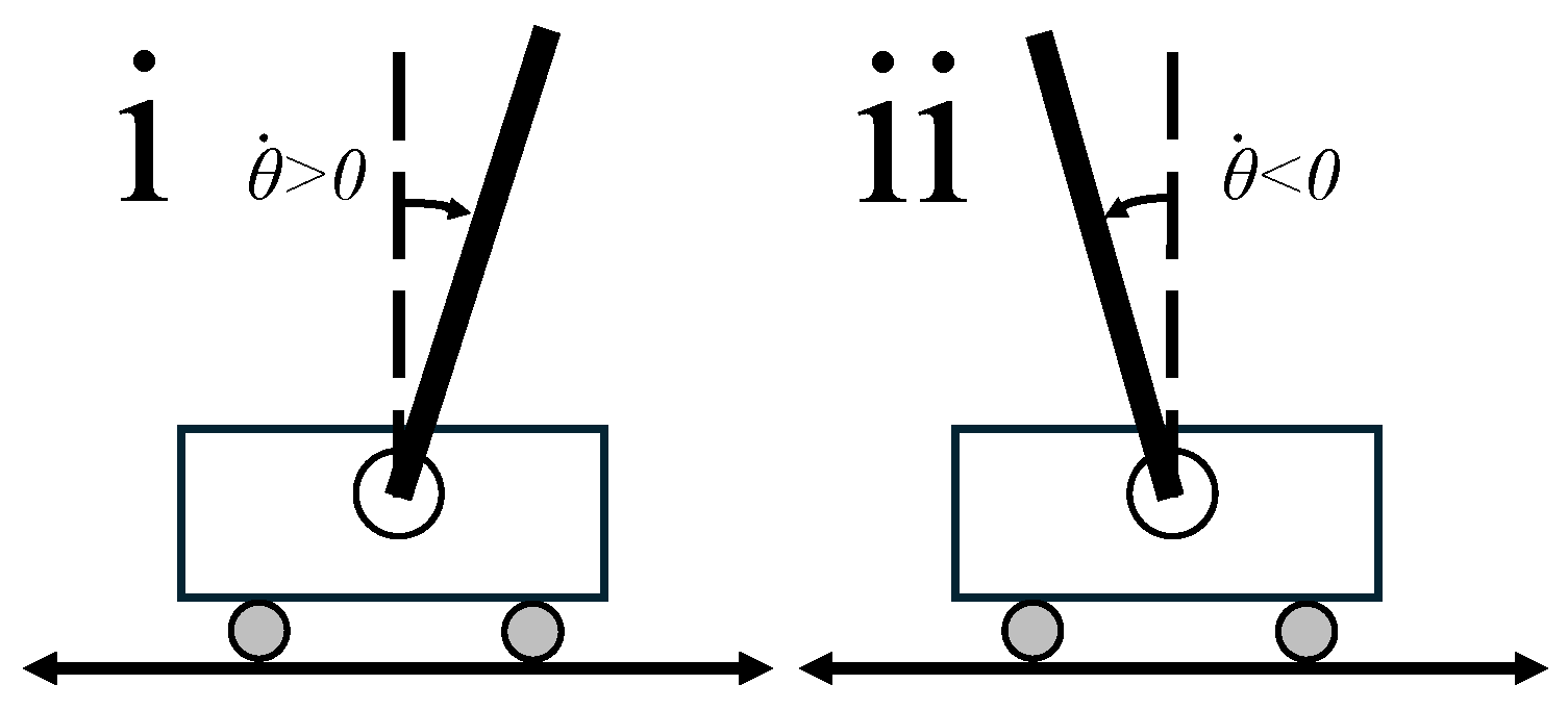
There are two cases when (
9) cannot be satisfied as shown in
Figure 4.
1): In this case, the candidate Lyapunov function can be defined as [
5]
where
is naturally the desired configuration since the pendulum is in the right half plane and has clockwise angular velocity.
whenever
which can be achieved (
) through the control input [
5]
2): In this case, the candidate Lyapunov function can be defined as [
5]
where
is naturally the desired configuration since the pendulum is in the left half plane and has counterclockwise angular velocity.
whenever
which can be achieved (
) through the control input [
5]
The swing-up controller switches between and or depending on the values of and .
IV. Stabilization
A. Linear Quadratic Regulator and Pole Placement
LQR controllers based on pole placement are known to quickly and smoothly stabilize the inverted pendulum in its upright and downward equilibrium configurations where the system dynamic equations can be linearized for
which is the source of all the nonlinearities in the system [
3].
1) Down Controller: If the magnitudes of the initial angle of the rod
, initial angular velocity of the rod
, initial displacement of the cart
, and/or initial velocity of the cart
are very large, the cart can end up very far from the origin
. In this case, although the pendulum can swing up to its upright position, stabilizing
while bringing the cart back to
either fails or takes a very long time. However, if there is a known method to swing the pendulum from its downward equilibrium configuration to its upright equilibrium configuration and maintain stability for a set of initial conditions
, we can force the pendulum to first achieve the downward equilibrium configuration before starting the swing-up control. Forcing the system to use such heteroclinic orbits through our energy control methods from the stable equilibrium to the unstable equilibrium forces global stability of our control method. Since the downward configuration of the pendulum is a stable equilibrium, it is inherently approached by the system without any control input. However, the process can be made exponentially quicker by an “initializer” that is designed using pole placement methods which is a trivially easy task. The control input will be in the form
where
,
,
, and
are gain constants and
is the rod angle from the downward equilibrium as shown in
Figure 5. In the case when
, we set
in order to not introduce unwanted energy into the system. For our system, the tuned controller gains that we use are
,
,
,
.
2) Up Controller: The up controller is applied whenever
:
Although this condition is sufficient for our design, various conditions can be added and explored to increase the stability or robustness of our controller or achieve a faster settling time. For instance,
and
can be restricted to be close to 0 to ensure that the system is already within the linearizable state when the up controller takes over. The controller can also be switched to the swing-up mode or the up stabilization controller can be disabled whenever
exceeds a certain bound. Moreover, if
exceeds a certain positive value and the pendulum is in the left half plane but outside the linearizable region of the upright configuration or if
drops below a certain negative value and the pendulum is in the right half plane but outside the linearizable region of the upright configuration, the controller can also be switched to the swing-up mode or the up stabilization controller can be disabled. From our preliminary investigations, such conditions interact and have coupled effects that need to be tuned in concert for optimal controller performance. The reader is encouraged to systematically explore the effects of these various conditions on the controller for future work. For our system, the LQR-tuned controller gains that we use are
,
,
,
.
B. Sliding Mode Controller
The sliding mode controller is a widely used nonlinear controller that is known for its robustness to system disturbances and model uncertainties [
9]. For these reasons, the sliding mode controller is one of the state-of-the-art control approaches for stabilizing the inverted pendulum. A sliding surface is chosen such that the controlled system converges to the surface and, upon reaching the surface, “slides” along the surface
s to reach and maintain the equilibrium state, as shown by some trivial Lyapunov function that is widely published in the literature [
11]. The control input is defined as
with design constant
K. To find
we let
and
in (
3) and solve for
:
Coupled sliding surfaces that stabilize
while tracking the error in
x were proposed for a conventional sliding mode controller following (
21) and a higher order terminal sliding mode controller following the control law
with design constants
and
were proposed in [
11]. In (
23), the saturation function
limits the value of a signal
z within a maximum
and a minimum
and is used instead of
to further control chattering:
After multiple attempts and modifications to the sliding surface mode controller values and architectures, we found that neither the conventional sliding mode controller nor the higher order terminal sliding mode controller proposed in [
11], nor do variations of these approaches can be tuned to stabilize our system fast enough to
and
. Stabilizing to
within
is possible but the stabilization in the drift in
x takes more than
. The reader is encouraged to try these approaches and come up with alternative sliding surface controller designs for future work. In contrast, our LQR up controller can consistently stabilize the system to
and
within
for any initial condition starting at
,
,
, and any
that follows our up controller condition
. If the initial conditions of the system fall within these specifications, the up stabilization controller is used; otherwise, the down controller is first used to bring the pendulum to the downward equilibrium, followed by swing-up and up stabilization.
V. Results
For our Lyapunov function based controllers, the tuned gains for the system are
and
and the switching occurs whenever
. We simulate the system response when using our controllers using MATLAB’s ode45 solver. When the initial conditions are
,
,
, and
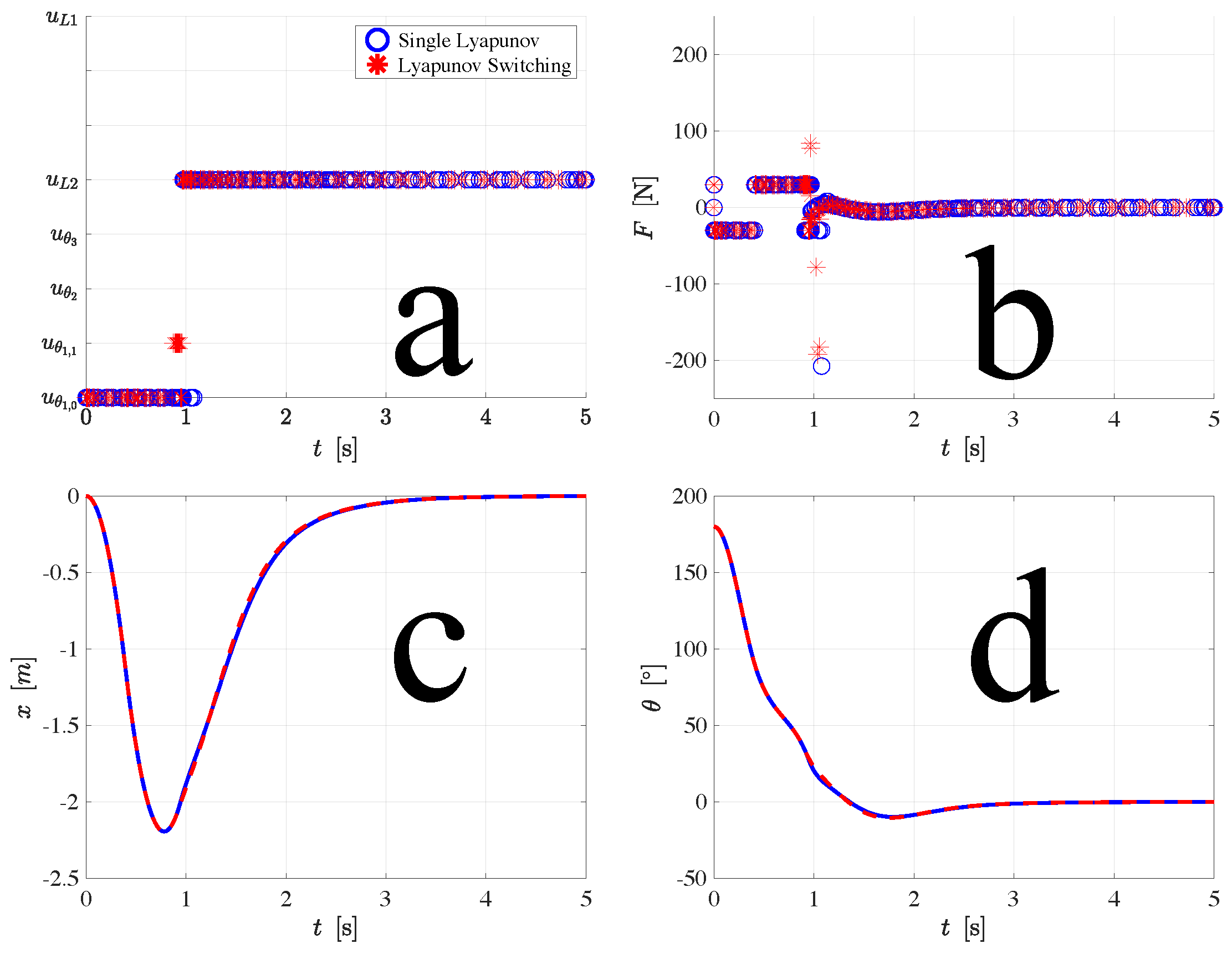
, the single Lyapunov and Lyapunov switching controllers behave very similarly as shown in
Figure 6, stabilizing the pendulum in one swing. This is true for a wide range of initial conditions, but not always.
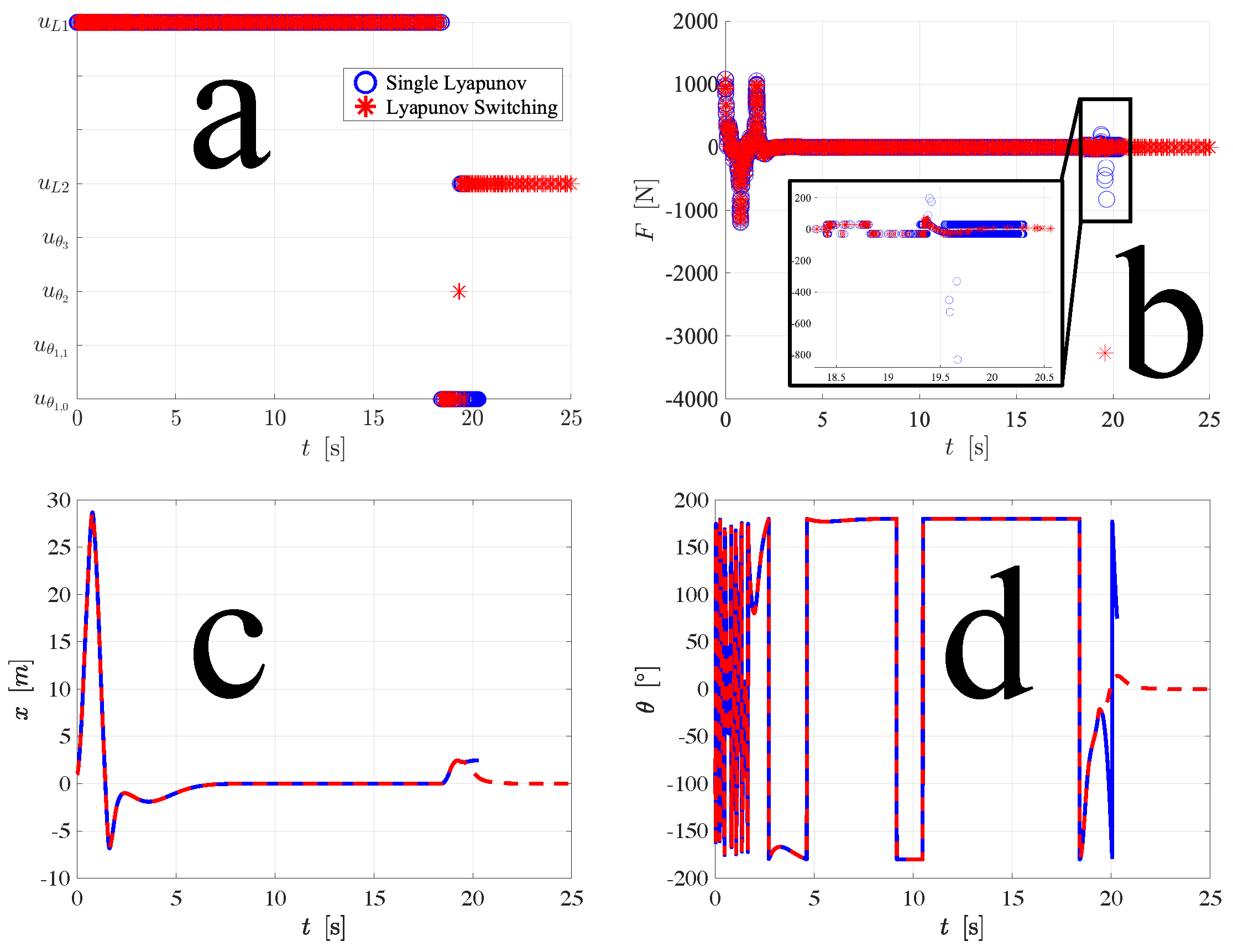
When the initial conditions are
,
,
, and
, the down controller first brings the pendulum to the downward equilibrium configuration. At around
, the swing-up controllers activate. The Lyapunov switching controller stabilizes the pendulum in one swing but the single Lyapunov controller fails and at
, the cart starts drifting to the right of
as shown in
Figure 7. Accompanying movies show the animations of the plots discussed herein.
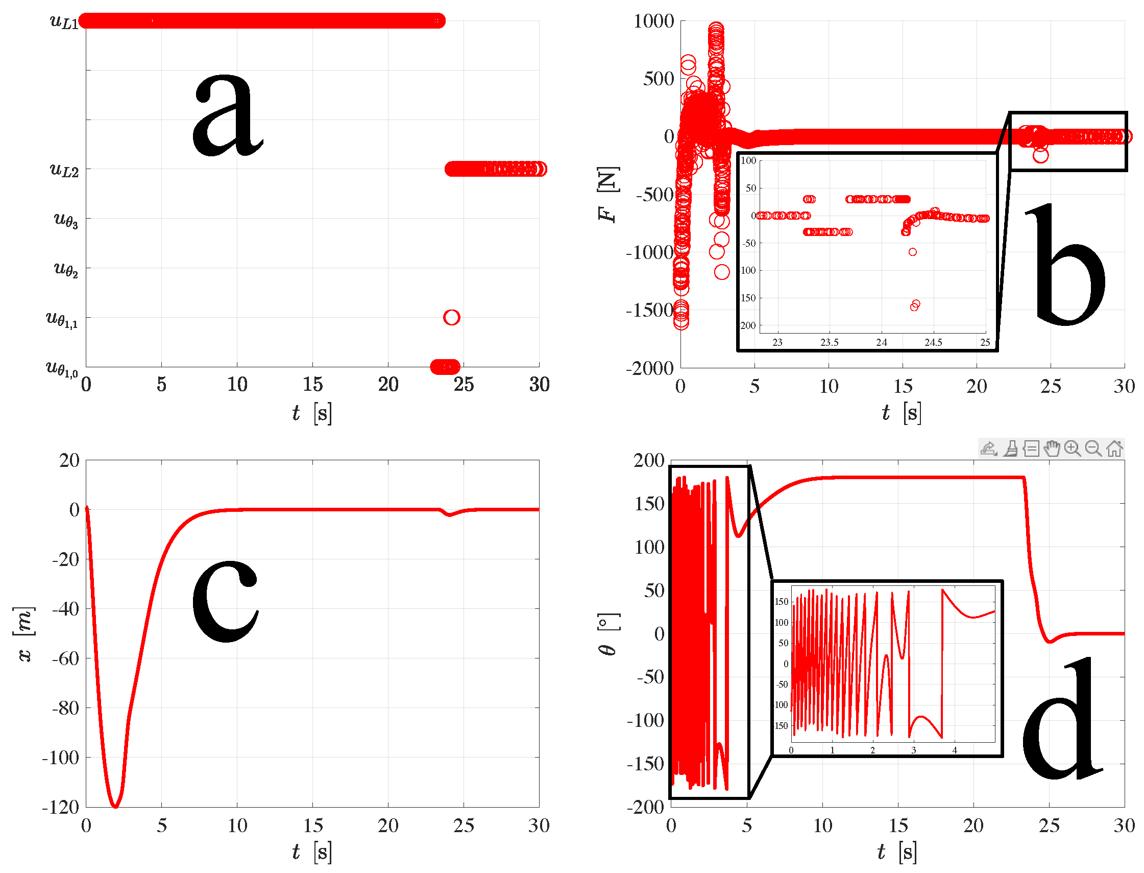
Even when the initial conditions are very far from the equilibrium configurations, we can force global stability using the down controller proposed in this paper. The system response using our Lyapunov switching controller when
,
,
, and
is shown in
Figure 8. The down controller first brings the pendulum to the downward equilibrium configuration. At around
, the Lyapunov switching controller activates and stabilizes the pendulum in one swing.
VI. Miscellaneous Controller Techniques
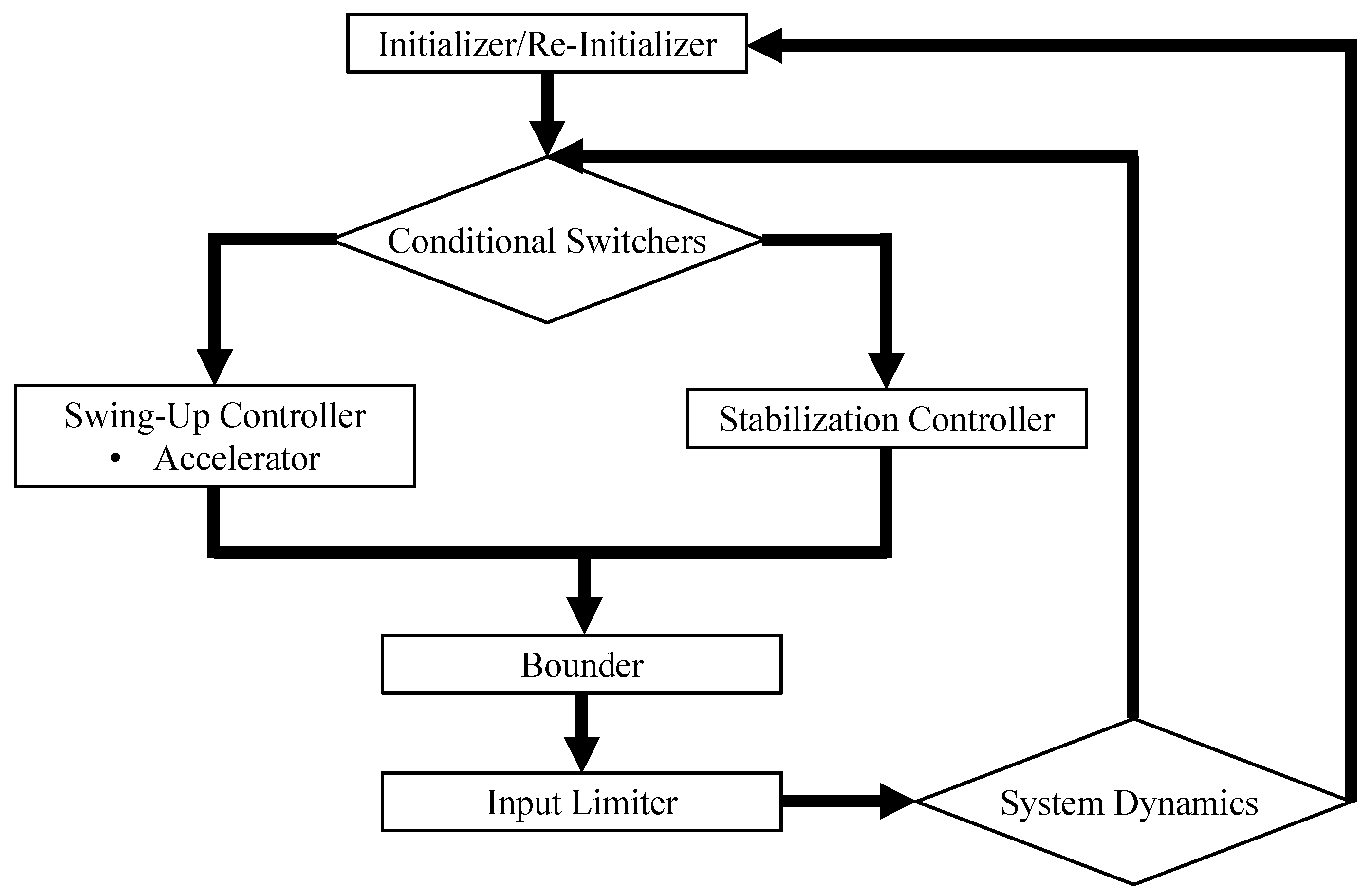
Various control techniques can be explored and augmented to our swing-up and stabilization controllers to increase the stability or robustness of our controllers or achieve a faster settling time. For instance, a re-initializer may be added to bring the pendulum back to the downward equilibrium configuration and at
whenever
exceeds a certain value. An “accelerator” or “Lyapunov converter” can also be added to guide the system at the beginning of the swing-up phase from the downward equilibrium. Depending on the initial proposed value of the Lyapunov controller at the start of the swing-up process, the accelerator either takes the absolute value of the calculated input
or
until
exceeds a certain value. A “bounder” helps contain the cart close to
. Whenever
x exceeds a certain value to the right of the origin, the bounder takes either
or a certain positive limit, whichever is less, negates it, and makes the resulting quantity the control input. Similarly, whenever
x exceeds a certain value to the left of the origin, the bounder takes either
or a certain positive limit, whichever is less, and makes it the control input. An “input limiter” converts the control input to 0 whenever
exceeds a certain value to eliminate spikes in the control input. From our preliminary investigations, these techniques, together with the optional switching conditions or “conditional switchers” discussed at the end of
Section A interact and have coupled effects that need to be tuned in concert for optimal controller performance. The reader is encouraged to systematically explore the effects of these various controller techniques for future work. A possible flowchart for the techniques discussed in this section and in
Section A is shown in
Figure 9.
VII. Conclusion
In this paper, we discussed the various state-of-the-art approaches used to stabilize the inverted pendulum on a cart system. Energy-based control methods, which are widely used to control and stabilize nonlinear systems are presented. A linear down stabilization controller is proposed to force the system to the downward equilibrium prior to swing-up. By forcing the system to follow heteroclinic orbits, global stability may be achieved.
We use multiple Lyapunov functions to ensure that the current Lyapunov function being tracked by the system is nonzero except when the pendulum is in the upright configuration, a theoretical condition that is not completely satisfied by the traditional Lyapunov function widely used for the inverted pendulum or variations of such a function. We have verified through simulations that using multiple Lyapunov functions improves the domain of attraction of the controlled system.
We also compare a linear quadratic regulator controller with sliding mode controllers for up stabilization. Our tuned LQR controller stabilizes the value of x and to the upward equilibrium configuration within . Although sliding mode controllers which are based on Lyapunov functions can stabilize the of our system to up to faster than our LQR controller, SMCs fail to stabilize x in a reasonable amount of time.
Various controller techniques that can be augmented to the swing-up and stabilization controller architectures for the inverted pendulum are proposed. These techniques can be explored in future work. An open-source MATLAB simulation code with our proposed controllers and controller techniques is provided for educational and future research purposes. Because of its simple practical design and complex underactuated dynamics, the inverted pendulum has been widely used since the 1980s [
12] to demonstrate a variety of ideas in nonlinear and linear control theory. Our source code contains the inverted pendulum system dynamics, allowing for modifications to the controller design, initial conditions, and system parameters. This flexibility accommodates the needs of future researchers and educators, making it a valuable tool for jump-starting their exploration or demonstration of the inverted pendulum system.
Supplementary Materials
The following supporting information can be downloaded at the website of this paper posted on
Preprints.org. This paper comes with supplementary movies of the animated inverted pendulum on a cart system driven by our controllers from various initial conditions. An open-source customizable MATLAB code for simulating and animating the inverted pendulum system is available in this link together with the supplementary videos:
https://github.com/generible/Inverted-Pendulum-Simulator.
References
- l aw Jakubczyk, B.; Respondek, W. On linearization of control systems. Bull. Acad. Polon. Sci. Ser. Sci. Math 1980, 28, 517–522.
- Shiriaev, A.S.; Fradkov, A.L. Stabilization of invariant sets for nonlinear systems with applications to control of oscillations. International Journal of Robust and Nonlinear Control: IFAC-Affiliated Journal 2001, 11, 215–240. [CrossRef]
- Kumar, E.V.; Jerome, J. Robust LQR controller design for stabilizing and trajectory tracking of inverted pendulum. Procedia Engineering 2013, 64, 169–178. [CrossRef]
- Lam, J. Control of an inverted pendulum. University of California, Santa Barbara 2004, 10, 24–37.
- Maeba, T.; Deng, M.; Yanou, A.; Henmi, T. Swing-up controller design for inverted pendulum by using energy control method based on Lyapunov function. Proceedings of the 2010 International Conference on Modelling, Identification and Control. IEEE, 2010, pp. 768–773.
- Bugeja, M. Non-linear swing-up and stabilizing control of an inverted pendulum system. The IEEE Region 8 EUROCON 2003. Computer as a Tool. IEEE, 2003, Vol. 2, pp. 437–441.
- Yoshida, K. Swing-up control of an inverted pendulum by energy-based methods. Proceedings of the 1999 American Control Conference (Cat. No. 99CH36251). IEEE, 1999, Vol. 6, pp. 4045–4047.
- Christensen, J.H.; Chistiansen, R. Swing Up and Stabilisation of an Inverted Pendulum on a Cart using Nonlinear Methods. Unpublished master theses. Aalborg East: Aalborg University 2017.
- Coban, R.; Ata, B. Decoupled sliding mode control of an inverted pendulum on a cart: An experimental study. 2017 IEEE International Conference on Advanced Intelligent Mechatronics (AIM). IEEE, 2017, pp. 993–997.
- Singh, G.; Singla, A. Modeling, analysis and control of a single stage linear inverted pendulum. 2017 IEEE international conference on power, control, signals and instrumentation engineering (ICPCSI). IEEE, 2017, pp. 2728–2733.
- Farooq, U.; Afzal, W.; Afaq, A.; Rehman, S. Stabilization Control for an Inverted Pendulum on a Cart: A Terminal Sliding Mode Approach. 2021 Fourth International Conference on Microelectronics, Signals & Systems (ICMSS). IEEE, 2021, pp. 1–6.
- Anderson, C.W. Learning to control an inverted pendulum using neural networks. IEEE Control Systems Magazine 1989, 9, 31–37. [CrossRef]
|
Disclaimer/Publisher’s Note: The statements, opinions and data contained in all publications are solely those of the individual author(s) and contributor(s) and not of MDPI and/or the editor(s). MDPI and/or the editor(s) disclaim responsibility for any injury to people or property resulting from any ideas, methods, instructions or products referred to in the content. |
© 2024 by the authors. Licensee MDPI, Basel, Switzerland. This article is an open access article distributed under the terms and conditions of the Creative Commons Attribution (CC BY) license (http://creativecommons.org/licenses/by/4.0/).
