1. Introduction
State-of-the-art conventional accelerators are quite large and expensive to maintain. Decades ago laser-driven plasma accelerators have been proposed as a future alternative by T. Tajima and J. M. Dawson [
1]. Laser-plasma wakefield acceleration (LWFA) is a promising approach for the generation of bright, ultrarelativistic electron beams for numerous applications in a compact manner. The basic principle employs a high-power, ultra-short laser pulse propagating through a low-density gas target generating a plasma wakefield leading to the separation of ions and electrons thereby building up an electric field of the order of 100
/
. Electrons that are trapped in this wake can be accelerated to energies in the
ange over very short distances (10
−2 range). Their advantages such as femtosecond pulse duration, and high peak currents make them attractive for a number of scientific and industrial applications [
2,
3,
4,
5].
Generally, 100
or even
cale laser systems are employed to drive such accelerators. There is a great interest in the pursuit of laser-plasma acceleration reaching electron energies in the
ange to drive advanced light sources such as free electron lasers or provide technical and scientific knowledge for linear colliders in high-energy physics [
6]. The realization of such applications relies on Tera- to Peta-Watt scale laser systems that operate at a few Hertz repetition rates [
7].
However, the required high-power laser systems are up-to-date only available in dedicated laser facilities that can provide the essential research environment. The operation of these systems is very demanding and requires large highly specialised groups with strong expertise. Nevertheless, various applications do not rely on such high-energy electrons. For example, lower-energy electrons (in the range of 10
) can be used in radiobiological experiments to study the effect of fractional dose delivery [
8]. Lower energy electrons can also be used in radiation hardness studies for space electronics [
5] and to investigate the dynamics of matter by ultrafast electron diffraction [
9,
10].
Available laser systems on the 100
scale run at
epetition rates or less and are predominantly based on the Ti:Sapphire technology. However, many applications would benefit from higher repetition rates. Despite providing less energy,
aser systems at
epetition rates combined with a post-compression scheme to reach few-cycle pulses and a tight-focus geometry have already proven their potential for a few
aser-plasma accelerators [
11] and for delivering e-beams with long term stability [
12]. In addition, recent advances in laser research such as multipass cell post-compression schemes [
13,
14], high-energy optical parametric chirped pulse amplification [
15] (OPCPA), or the use of alternative laser media (e.g. Yb) [
16,
17] are promising developments toward suitable lasers for driving robust and reliable laser-plasma accelerators (LPA) for real-life applications.
In this work, we introduce the e-KAIO (electron Kit-All-in-One), which is a joint effort with the company SourceLAB and a first step towards making LPA technology more accessible to a broader community in scientific research and industry. The main goal of the e-KAIO-beamline is to overcome the current weaknesses of laser-plasma accelerators by mainly employing industrial standard components to realize a much more cost-effective, compact, reliable and easy-to-use laser-plasma accelerator. To this end the interaction chamber is combined with an industrial grade laser system and possibly an intermediate post-compression scheme will be added in the future.
Here, the first proof-of-principle experiments will be presented, demonstrating the functionality of the e-KAIO chamber. In
Section 2 we will discuss the challenges of laser-plasma-acceleration (LPA) specifically at high repetition rates before giving a technical overview of the e-KAIO submodule and its advanced diagnostic specifically designed for LPA and its application in
Section 3. This includes a detailed characterization of the Coherent Astrella laser system as a driving laser crucial for a controlled laser-plasma interaction. Afterward, we will present and discuss our first results in
Section 4 and give an outlook toward future experiments in
Section 5.
2. Design Criteria for LPA at High Repetition Rates
To design a laser-plasma-accelerator it is important to consider the involved scaling laws to estimate the expected electron energies for a given driving laser. Furthermore, there are certain aspects regarding the experimental design when dealing with LPA at high repetition rates that we will discuss below.
Depending on the experimental conditions, there are several different regimes where electrons can be accelerated effectively. Sub-relativistic electron beams with relatively low charge can be produced utilizing the density down-ramp injection [
18,
19], when working with laser pulses of a few
t tens of
ulse duration. Using ultrahigh-density gas targets, the authors of Salehi et al. [
20] were able to produce relativistic electron beams at
epetition rate operating in the self-modulated regime. The resulting electron beam is fairly divergent and has a Maxwellian distribution. To reduce the energy spread of the electron beam it is favourable to work in the so-called blow-out or bubble-regime [
21,
22,
23,
24,
25]. The resulting electron beams typically have a small divergence while still maintaining relativistic energies, which makes them highly suitable for numerous applications. Provided the electron injection is properly controlled, the scaling law of Lu [
26] can be used to predict the acceleration gradients generated in such strongly non-linear plasma wakefields. To optimize the output energies, the experimental conditions have to be tuned for the laser pulse to be in resonance with the created plasma cavity. Assuming a near-spherical shape of
R (given by half the plasma wavelength
) both the transverse and longitudinal pulse size have to be of similar dimension, i.e.
, where
c is the speed of light,
the pulse duration, and
the beam waist. By matching the transverse dimension of the laser pulse and the plasma cavity, one ensures that the ponderomotive force exerted on the electrons is balanced by the Coulomb force of the ions inside the plasma cavity. In addition, the laser-plasma interaction leads to etching via energy depletion and red shift of the pulse over a length
. Ideally this pulse degradation is limited to the time that the electron bunch is in phase with the plasma wakefield within the distance
- leading to the second condition
. When both conditions are met, the maximum wakefield amplitude is
, where
is the cold wavebreaking field,
the electron mass,
the plasma frequency and
the normalized vector potential of the driving laser of frequency
. The maximum electron energy gain is then given by
In addition to the spatial resonance discussed, the above laser propagation plays a crucial role as the dephasing length usually exceeds the Rayleigh range given by the chosen focus geometry. To extend the interaction length (such that maximum electron energy gain can be reached) one utilises the effect of self-focusing which counteracts the diffraction effects and helps to maintain the transverse and longitudinal resonance. For self-focusing to occur the peak power
P of the laser pulse should exceed the usual threshold for relativistic self-focusing
, this
. As found by Lu et al. [
26], when working in the bubble regime this condition has to be altered to
as the wakefield has a predominant effect on the propagation.
Following the scaling laws, one usually finds that for laser systems operating at epetition rate, the resonance conditions place high demands on the experimental conditions.
Due to the limited pulse energy of high repetition rate laser systems, one usually has to work in a tight focusing geometry to reach the limit of relativistic self-focusing, which is a requirement for electron injection in any regime. At very high target pressures, electron injection can be achieved even for pulse energies of a few
[
20] and pulse durations around 30
even outside the bubble regime. To optimize the electron acceleration and beam quality an additional post-compression scheme has to be employed to work in the bubble regime by lowering the pulse duration. In the extreme limit, this means working in the few-cycle regime, where effects based on the carrier envelope phase (CEP) can modify the electron output characteristics [
27]. For a given pulse energy
and
at a fixed value for
one can find the required beam waist
and pulse duration
. The lower the pulse energy, the shorter the focus geometry and pulse duration have to be chosen, leading to dephasing and Rayleigh lengths of tens of
Consequently, the gas targets used should have density gradients of similar dimensions or even smaller to optimize the coupling of the laser into the jet and avoid ionization-induced defocusing [
28]. In addition, the electron density needs to be on the order of
to reach the resonant regime as
. To ensure the laser does not damage the gas nozzle the interaction region should be at least 100
above, which can be realized by using super-sonic or shocked nozzles [
29,
30]. Extensive diagnostics must be implemented to check the target and plasma density distribution above the jet. In addition, a pump-probe line is needed to observe the plasma processes with sufficiently good temporal resolution and check the target condition between successive laser interactions (no pre-ionization). Finally, the target gas should flow continuously to allow operation at high repetition rates while maintaining an ambient pressure of 10
−2 inside the interaction chamber.
3. e-KAIO Chamber and Laser Plasma Diagnostics
The progress of laser plasma accelerators in the last decades has established this technology as a potential candidate for future accelerators not only for research but also for industrial and societal applications. The numerous advantages of LPA-produced electron beams (micrometre-scale source size, femtosecond pulse durations, high peak currents) make them ideally suited to ultrafast electron diffraction, non-destructive imaging, radiobiology, or space radiation production. At high repetition rate, LPA electron sources are particularly appealing as they offer long-term stability and real-time access to statistics [
31], enabling efficient complex parametric studies (e.g. in radiobiology [
32]). This is supported by the fast progress in laser development, as by now there are multiple industrial-grade laser systems that are suitable as potential drivers at kHz
epetition rates. These laser systems offer high reliability and ease of use, while still fulfilling the demanding output requirements for driving LPA.
Nowadays LPA sources can be found mostly in the scientific community as operating these highly complex systems requires a lot of expertise and experience. Thus, implementing LPA sources at high repetition rates for applications remains challenging, as LPAs require laser drivers with both high average and high peak power, high-performance vacuum handling to manage the large target gas loads and adequate management of large data sets generated during measurement runs.
The novel e-KAIO-beamline aims at addressing these challenges by combining three key ingredients: (i) an industrial high average power laser system, (ii) a versatile temporal pulse post-compression stage and (iii) a compact electron accelerator module with integrated user interface and data management system. The e-KAIO-beamline approach is compatible with a wide range of commercial laser platforms, as it is modular and features versatile post-compression based on multi-pass cell technology [
13]. Secondary electron and betatron radiation production is coupled to an automatic high repetition rate data acquisition program, which monitors and logs all relevant parameters during day-long experimental runs.
In the following we will discuss two major sub-components of the e-KAIO-beamline, focusing on the e-KAIO chamber itself and the Astrella laser system by Coherent as a potential driver for LPA.
3.1. Interaction Chamber
The e-KAIO chamber is designed to produce
evel electron beams at
hen the accelerator is driven by few
few
elativistic laser pulses. A user-friendly system allows fine adjustment of the central parameters essential for high-quality beams. These parameters include among other things the control of the laser beam alignment, the control of focal spot quality, the control of gas jet position, density, and profile, and the electron spectrometer dispersion. Depending on the pulse length of the driving laser beam, different regimes of the laser-plasma interaction can be reached, thus offering different electron output characteristics as discussed in
Section 2 above. The e-KAIO is versatile and can be used in combination with different driving lasers and used for various applications. In the following, we will discuss the different sub-components of the system and show, how it is perfectly adapted to tackle the challenges of high repetition rate LPA.
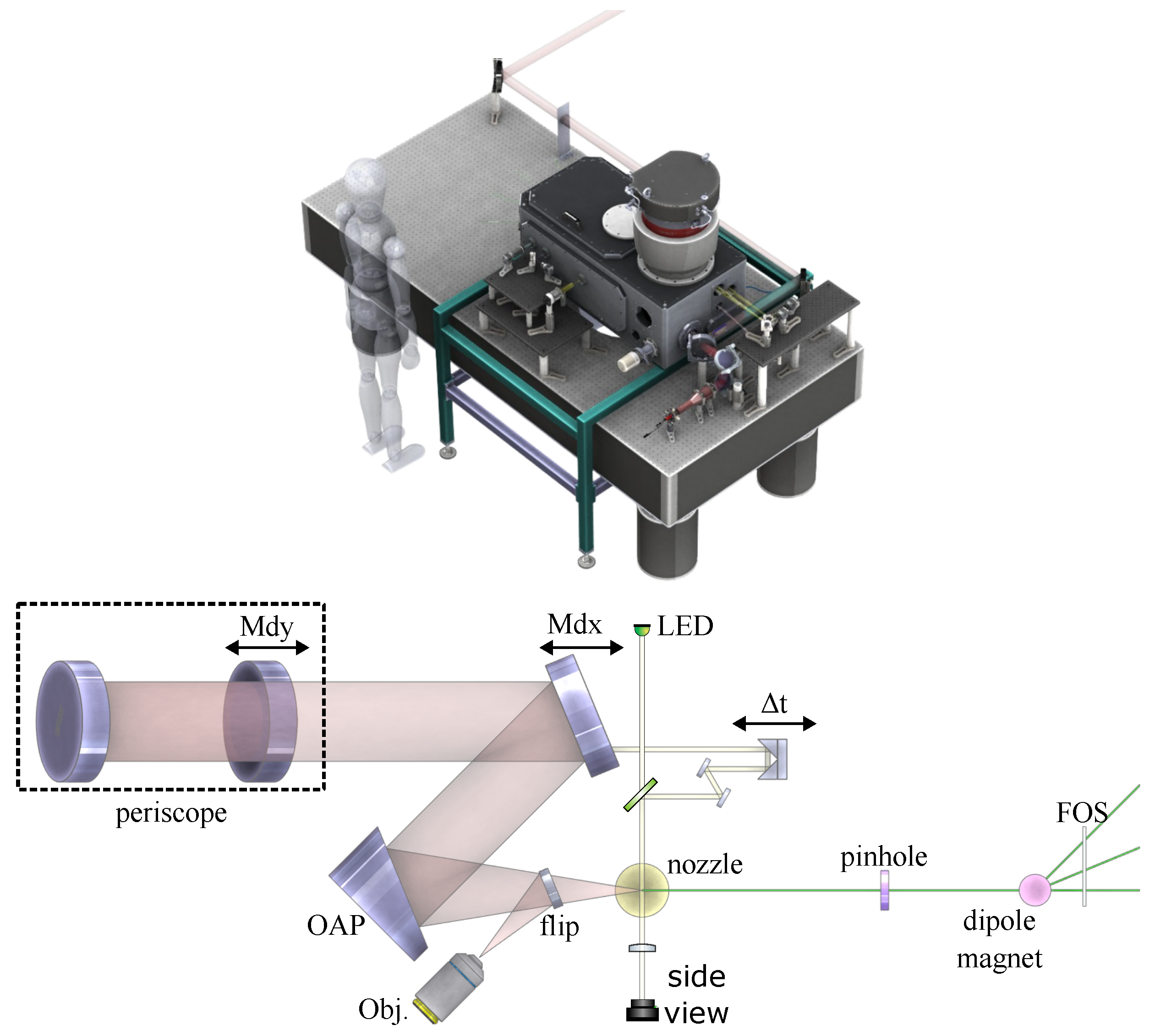
The e-KAIO vacuum chamber is shown in
Figure 1 (left) and can be operated even in small experimental areas. The vacuum chamber itself is carried by an outer support structure and the inner breadboard is mechanically isolated from the chamber walls by flexible bellows to reduce vibrations produced by the pumping system or the surrounding. The dimensions of the vacuum chamber itself are 500 × 900 × 450
and the optical entrance window supports beam diameters up to
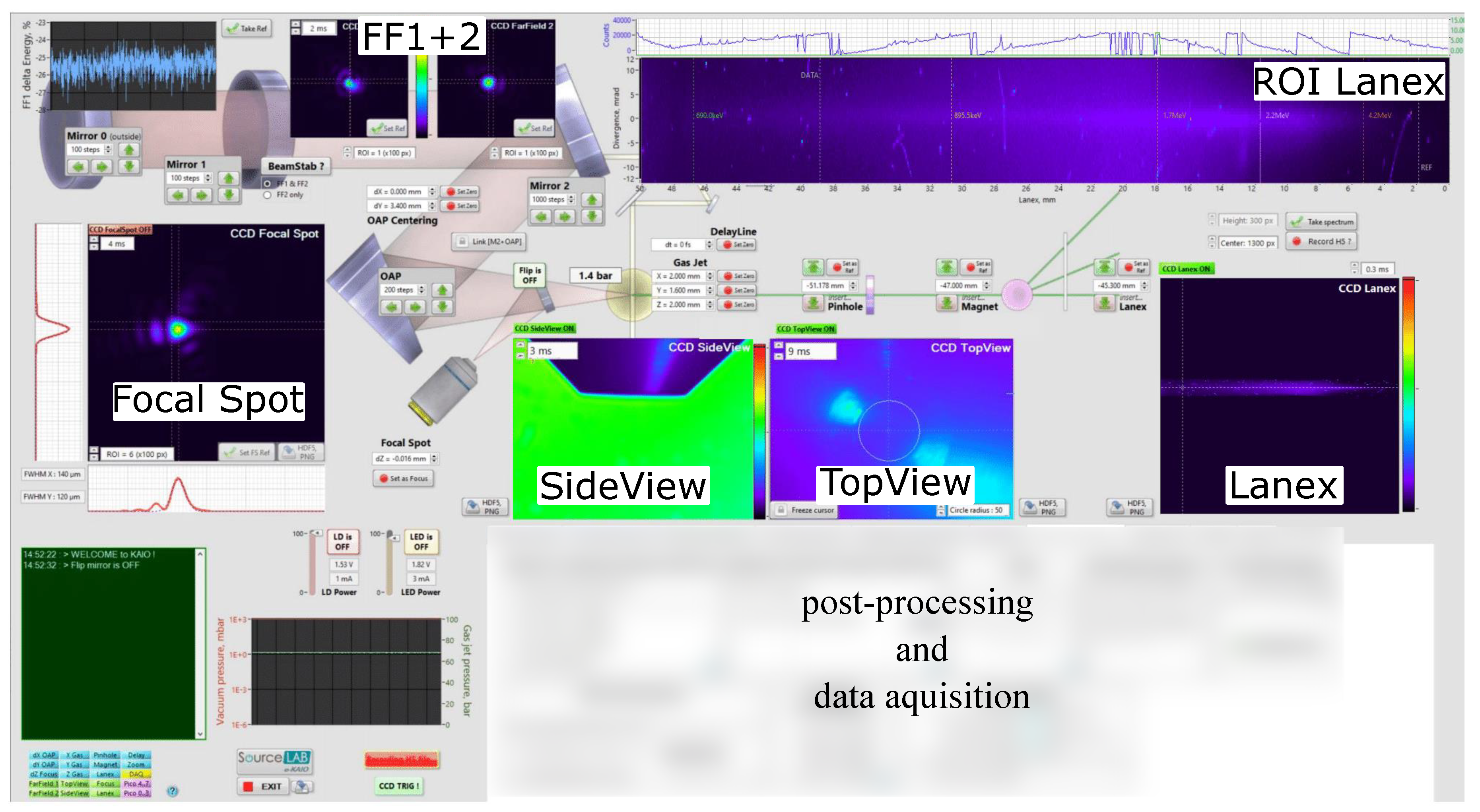
. The e-KAIO chamber provides multiple diagnostics for monitoring the laser beam or studying the electron beam. The optical diagnostics are installed outside of the chamber including six CCD cameras which are connected to the KAIO control computer. A detailed overview is shown on the right in
Figure 1. The input beam is recorded by two reference CCDs which can be used for alignment references, thus enabling a quick realignment procedure from day-to-day operation. In addition, the references can be used for active beam stabilization as they are coupled to piezo-motors controlling the position and pointing of the input beam. In this mode, the drift or misalignment of the focus will be corrected automatically by moving the pico-motors of the two last mirrors before the focusing off-axis parabola. This option is useful during the pumping of the chamber under conditions of strong vibrations and/or mechanical stress, as well as during long-term system operation. The alignment references are shown in the upper left of
Figure 2 and the integrated signal of one of the cameras can be used to track the average power stability of the laser. In addition the deviation from the set reference can be recorded to investigate the beam drift and pointing under different conditions. For pre-alignment purposes, the e-KAIO chamber is equipped with a red alignment laser diode, which has the same path and close central wavelength as the actual femtosecond laser. This allows one to align equipment without having to use a high-intensity laser. The mirrors and off-axis parabola used for focusing the beam are motorized and can be positioned via the control unit and the dedicated computer. The beam is focused by a
or
off-axis-parabola and the attenuated focal spot can be imaged by an objective when the flip mirror in front of the gas jet is up. The gas jet is installed on a 3-directional translation stage and can be moved with micrometer precision. During the interaction of the high-intensity laser beam and the gas jet electrons are accelerated which follow the axis of the main laser beam direction. These electrons are detected via a scintillator (Hamamatsu FOS J6677) screen, and the converted visible light is further recorded by a CCD camera after passing an interference filter. Additionally, a magnetic spectrometer can be implemented in the electron beam axis as needed.
The spectrometer consists of a pinhole and a pair of permanent magnets positioned on individual translation stages. By adjusting the distance of the magnets the magnetic field strength can be adjusted to vary the electron dispersion. The field strength is pre-calibrated and the dispersion axis is shown in the user interface (upper right in
Figure 2). At the back of the interaction chamber are multiple vacuum flanges to connect to a beamline for further manipulation of the electron beam or measuring the source output.
3.2. User Interface and Data Acquisition
The e-KAIO beamline has a Graphic User Interface (GUI) that allows online control of all parameters and data acquisition. In
Figure 2 the user-friendly GUI overview of the e-KAIO chamber is shown. The interface supports the multiple CCD cameras, the several motorized translation stages, the piezo-motors for driving the mirrors, and also the data acquisition and storing. The interface not only allows monitoring and adjusting the parameters but also has a quick analysis of the focal spot and electron density, for instance. Similarly to the INSIGHT algorithm, the e-KAIO software has an implemented GS algorithm to measure the spectrally averaged wavefront of the laser beam. The recorded images and values are stored in HDF5 files giving the possibility to store large amounts of data. To reproduce and keep track of the experimental conditions used, a tagging function is included in the HDF5 file saving option.
3.3. Laser System and Diagnostics
The first experimental studies were carried out with the Astrella laser provided by Coherent. This Astrella laser combines industry-leading performance and durability. Having a tabletop, one-box size enables the availability for various applications and operating conditions. The Astrella laser system delivers up to 9
/pulse and a pulse range of [range-units = single]35100
at a repetition rate of 1
. The nominal beam diameter is around
at a divergence angle of
. Different measurements were performed employing various devices to characterize the laser system. Temporal characterization is achieved using TIPTOE [
33], which is a broadband time-domain autocorrelator. By adapting the scanning range of the device one can either characterize the main pulse to get access to the temporal shape and its spectral phase, or one can scan a wider temporal window to check the
ontrast.
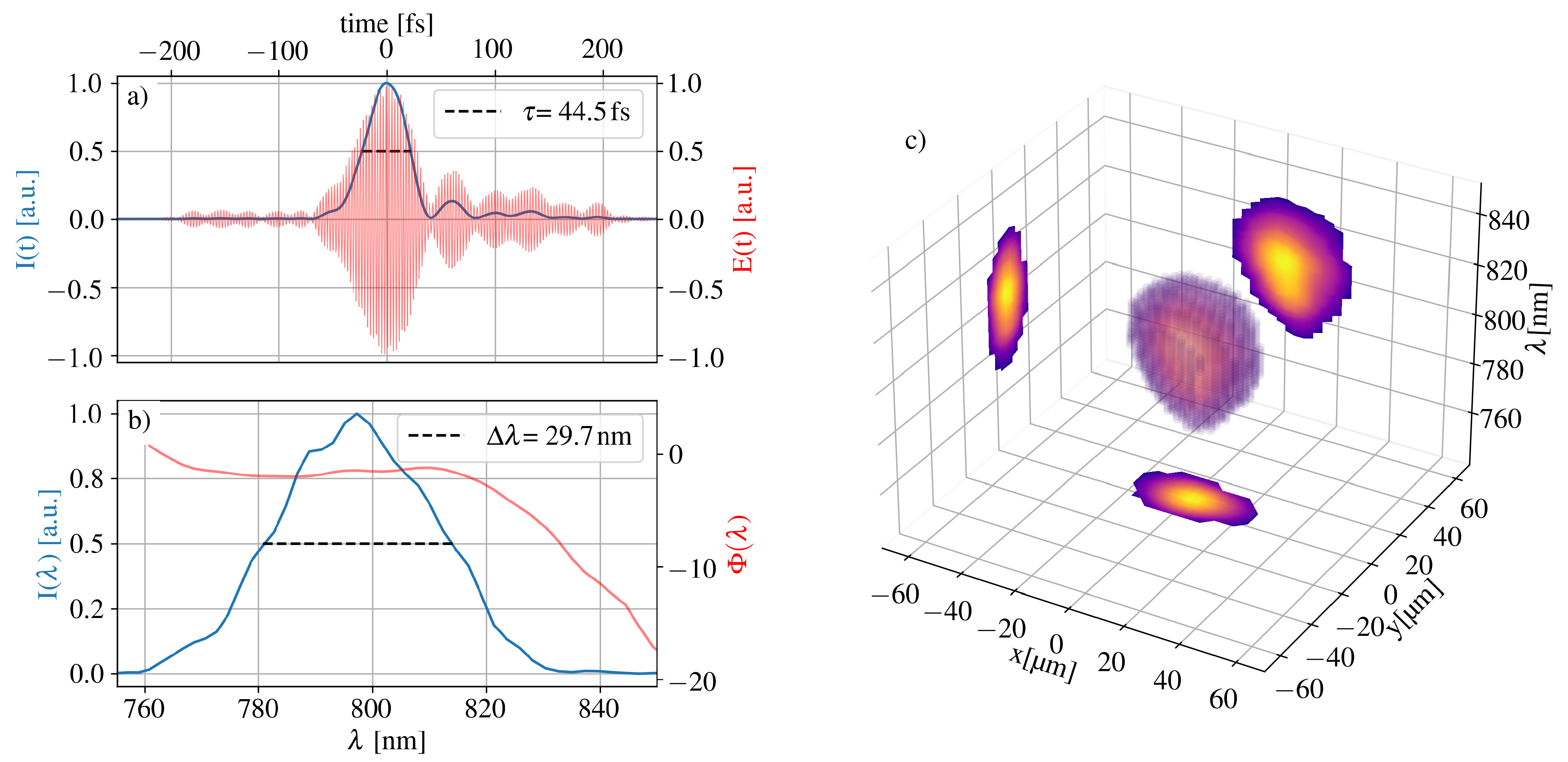
The pulse measurements are plotted in
Figure 3. The strong third-order dispersion of the spectral phase (b) limits the pulse duration to
and leads to additional side peaks after the main pulse (a).
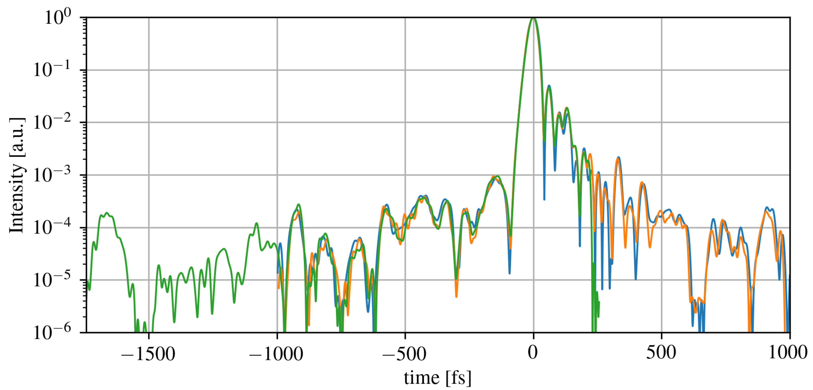
Figure 4 shows the temporal contrast of the Astrella laser pulse determined with the TIPTOE device. The three differently colored traces represent measurements that were performed within two months. The laser system is proven to be stable within its specifications, and the contrast measurements were reproducible. Assuming a peak intensity of 1d18
/
, the temporal contrast is reasonably good to prevent pre-ionization of the gas target between two consecutive shots, when using helium or argon.
The measurements taken by TIPTOE provide a spatially averaged signal, since the device integrates over the entire ionization volume at the laser focus. Thus the measurements are insensitive to any spatio-temporal-couplings (STCs). For this reason, another device, the so-called INSIGHT [
34] (SourceLab), was used to characterize the spatio-temporal distribution of the laser pulses. The INSIGHT measurements are done focusing the laser beam using a
achromatic lens and a spatially resolved spectrum is taken at the focus and one each before and after at approximately
. The spectrally resolved wavefront can be recovered using an adapted version of the Gerchberg-Saxton (GS) iterative algorithm [
35]. In
Figure 3(c) the three-dimensional spectrally resolved focus is shown. The spectral components are well aligned along the propagation axis, which indicates there are no significant STCs such as pulse front tilt or higher order effects, which reduce the far-field intensity.
4. Experimental Results
The control of the target pressure profile is a key aspect of electron acceleration experiments. When working with kHz aser systems, the target nozzle operates in continuous flow which, depending on the backing pressure, target gas, and nozzle size, can put a high gas load on the vacuum system. The pumping system of the e-KAIO chamber can conveniently be modified to some extent to accommodate these high gas loads and still keep the chamber pressure in the 10−3 range. In addition, the laser-plasma interaction needs to be optimized and monitored to understand the underlying physics of the resulting electron spectra. To this end, the laser focusing is optimized and the target density profile is characterized as the laser wavefront and the target density profile play a major role in the formation of the accelerating wakefield.
4.1. Differential Pumping
The basic e-KAIO vacuum pumping system is a combination of one primary rough pump (Edwards iXL120) and two turbo pumps (Pfeiffer HighPace
2300) with a suction of 2000
/
−1 each. In addition, a differential pumping configuration can be implemented to reduce the load on the turbo pumps. For the first proof-of-principle experiments, the e-KAIO is equipped with a pumping system consisting of two roughing pumps with a suction power of 120
/
−1, one for the differential pumping close to the nozzle and the second one as a backing pump for the upper turbo pump. The connection of the optional bottom turbo pump was covered by a blind flange. A pressure gauge directly connected to the e-KAIO control unit enables monitoring and saving of the values continuously via the KAIO GUI. Without gas load, chamber pressures of low 10
−6 to a few times 10
−7 could be reached.
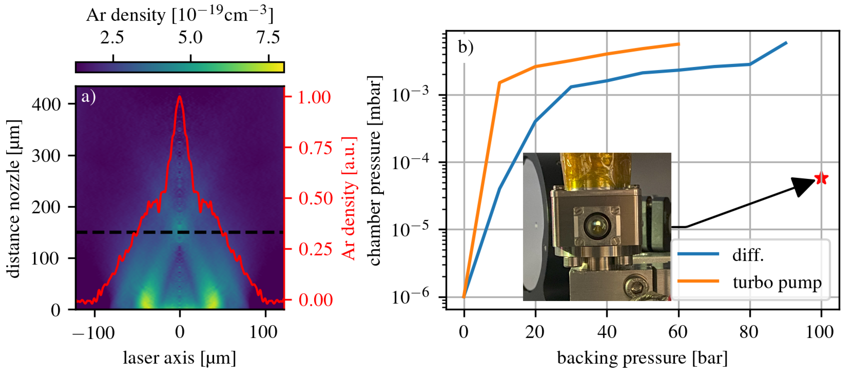
Figure 5 b) shows the measurements for the different pumping systems. In the differential pumping case (blue line), a tube connected to a roughing pump was placed a few centimeters on top of the gas nozzle to reduce the load on the turbo pump. This simple differential pumping system already improved the chamber pressure enough to be able to operate the nozzle at a backing pressure of 90
. Without a differential pumping system (orange line) already at a backing pressure of 60
a chamber pressure of 5.8 × 10
−3 is reached due to the high load on the turbo pump. To further optimize the gas load handling a more advanced differential pumping scheme was implemented were the interaction region in enclosed by a differential pumping cube. Thus the gas leak into the vacuum chamber is limited to the openings for the laser beam. The probing of the interaction region is maintained by thin windows on either side of the cube.
The valve of the gas nozzle is driven via PulseLAB, a digital pulse driver manufactured by SourceLAB. The device is triggered externally and can for instance be synchronised with the laser pulse. PulseLAB allows different modes to operate the nozzle: single-shot, continuous, or burst mode. The delay and opening time of the valve relative to the external trigger can be set in the control panel or in the PulseLAB software.
4.2. Nozzle and Gas Density Characterization
Two different gas nozzles were used to test the diagnostics and gather the first experimental results. A metallic symmetrically shocked nozzle [
29] provided by SourceLAB and a supersonic glass nozzle produced by LightFab were tested using argon as a target gas. Due to manufacturing reasons, a glass nozzle could provide a smoother density profile. A drawback of the glass nozzles is their lower robustness to high backing pressure.
The gas density was determined by exchanging the side view camera of the e-KAIO chamber with the SID-4HR PHASICS camera [
36,
37] for interferometric measurements. Using the PHASICS camera software add-on density module and the white backlight of the KAIO chamber, the target density can be determined. The module performs an inverse Abel transformation of the phase shift projection to extract the atomic gas density by assuming a rotational symmetric gas jet. This is well justified for round nozzles. The resulting atomic density was found to be 3 × 10
−19 cm
−3 for a backing pressure of 100
. The recorded image is presented in
Figure 5 a). The FWHM of the gas jet profile is about 50 μ
. For imaging the gas jet onto the camera, a lens with a focal length of 10
was placed on the axis of the side-view camera. The magnification is approximately 15.
4.3. Laser-Plasma-Interaction
First experimental efforts to generate electrons with a
laser system employing the e-KAIO chamber made successful progress in bench-marking the system. Various diagnostics and subsystems were tested and proven to be operational. In the first phase of the experiments, the Coherent Astrella Ti:Sa laser system was used to drive the electron source. To minimize focal spot size, the Astrella beam is expanded by a factor 4 mirror telescope to a diameter of around
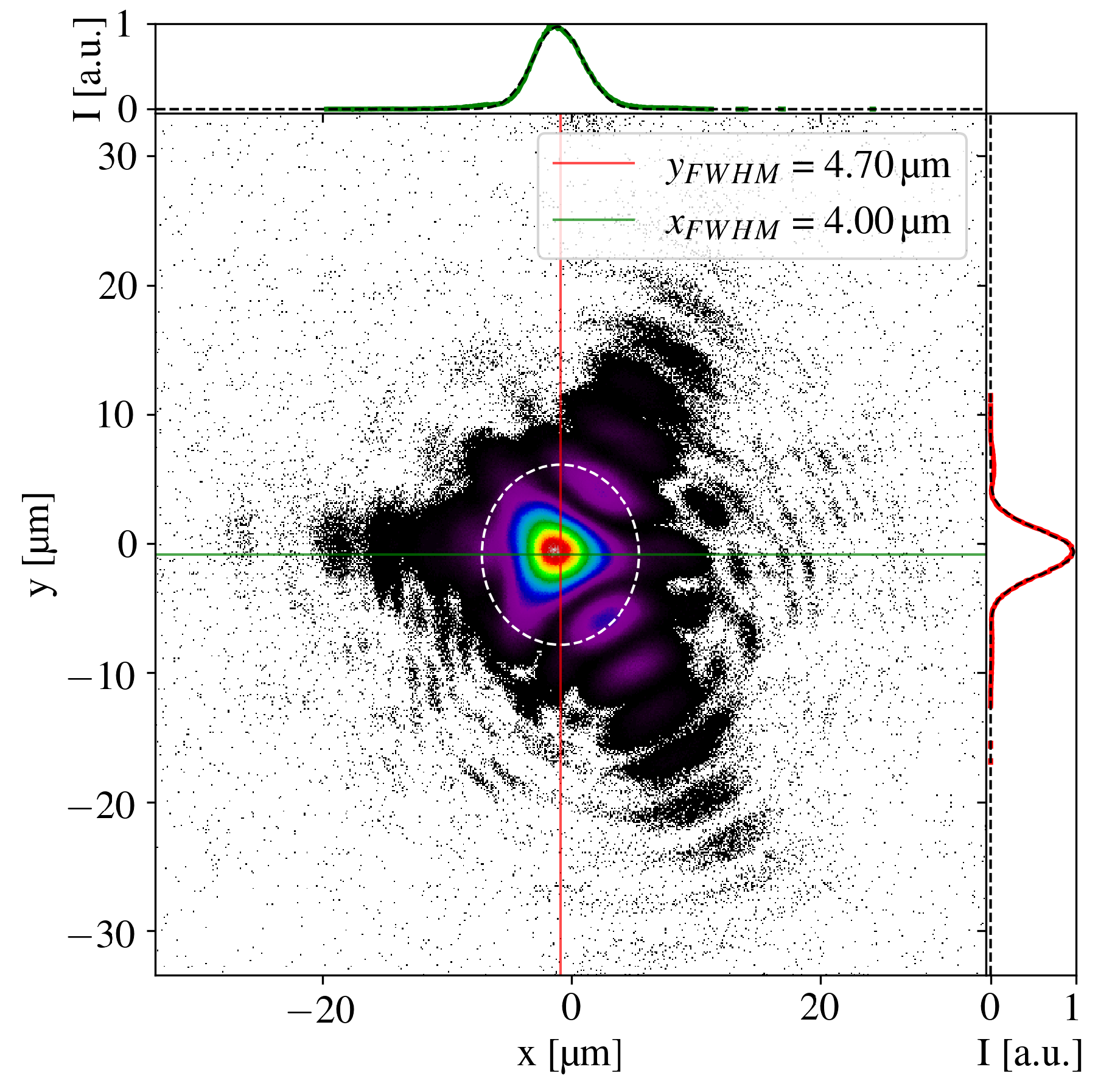
before the focusing optic. The focal spot of the beam focused by an
f/3 parabolic off-axis mirror is shown in
Figure 6. The graphs show a line out in the vertical (red) and horizontal (green) directions. The focal spot size (FWHM) is found to be approximately 4.00 μ
in the horizontal direction and 4.70 μ
in the vertical direction. The focus appears to have a trefoil shape which is due to the manufacturing of the parabolic mirror. This shape leads to an energy loss of the laser focus in the wings of the focus. Considering the additional losses by the optics between the laser exit and the focus and the spread in time due to dispersion effects (see
Figure 3(a,b)) the main pulse has an estimated peak intensity of
4 × 10
17W/cm
2. This calculation assumes a pulse energy of
on target and a pulse duration of
as found by the TIPTOE measurement
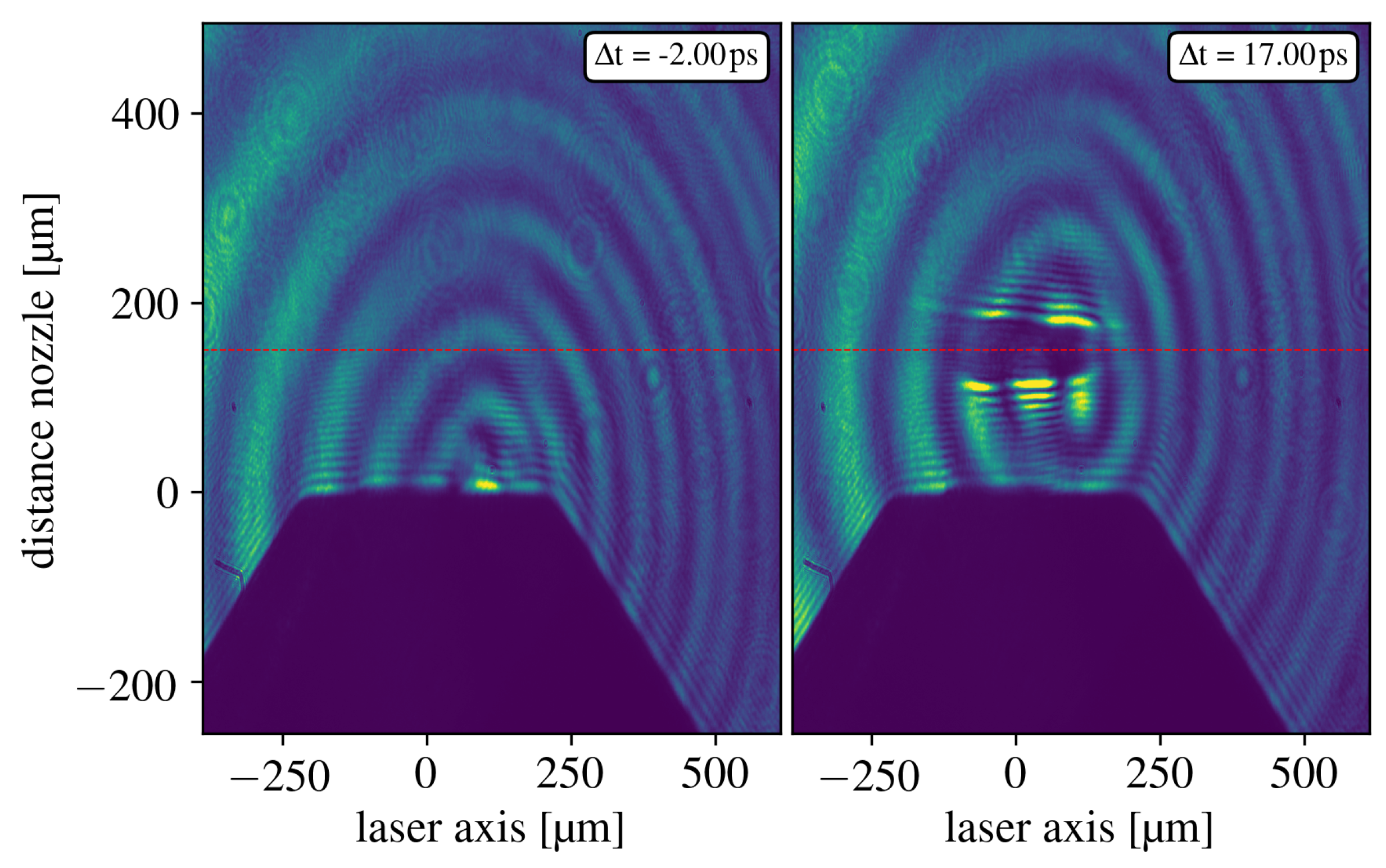
The laser-plasma interaction was visualized via a shadowgraphy imaging line. The side-view imaging line is equipped with a delay stage to capture different moments of the laser plasma interaction. The exact position of the mirror to adjust the delay
can be controlled within the GUI.
Figure 7 shows the interaction at two different delays. The left-hand-side image serves as a reference since in this case no laser pulse was present. In the right-hand-side image, the propagation of the laser pulse through the gas target can be observed. The delay between the laser pulse and the probe pulse on the right side of
Figure 7 is 17
. The delay is marked in the top right corner of each image. The Airy pattern in the background is due to the probe beam passing through the holed mirror when extracted from the main beam. An interference filter selecting narrow-band wavelengths around 800
is placed in front of the CCD camera to block the plasma light and other residual ambient photons.
5. Conclusion and Outlook
We present the e-KAIO chamber, a sub-module for the e-KAIO-beamline, a versatile electron accelerator for various applications. Our first proof-of-principles experiments demonstrated the capability of the e-KAIO chamber to accommodate an industrialized laser system. The first results show that the alignment and data acquisition using the e-KAIO chamber is straightforward and can be easily carried out in different laboratories or working environments. To achieve shorter pulse duration and higher intensities it is foreseen to repeat the experiments with a post-compression stage. This implies that, by using higher intensities at shorter pulse durations, it is possible to reach the point where the laser and target parameters interact in a way that is conducive to effective electron acceleration.
The e-KAIO interaction chamber is a first step in reaching the goal of a table-top laser-plasma electron accelerator on a university scale accessible for different potential applications. It can provide a structural change in the availability of laser plasma accelerators that will advance the research and progress of developing a system suitable for industrial applications. This will give opportunities to drive the research forward and make electron accelerators available on a smaller scale. Therefore, research and applications will advance further.
Author Contributions
Conceptualization, M.B., J.F., and F.S.; methodology, J.F., and F.S.; software, C.S., V.E.N., C.G., and A.D.; validation, C.G., E.A., C.S., V.E.N., A.D., and R.A.; formal analysis, C.G., and A.D.; investigation, C.G., E.A., C.S., V.E.N., A.D., and R.A.; resources, F.S., J.F., and R.L.M.; data curation, C.G., and R.A.; writing—original draft preparation, C.G., and E.A.; writing—review and editing, C.G., M.B., F.S., R.A., and J.F.; visualization, C.G., and C.S.; supervision, F.S., J.F., R.L.M. and M.B.; project administration, F.S., C.G.; funding acquisition, M.B., J.F. and C.M.S All authors have read and agreed to the published version of the manuscript.
Funding
We acknowledge the support from the Helmholtz association fund ATHENA in the framework of the JuSPARC project. Furthermore, the research was funded by a joint project of the German Scientific Council (DFG-project BU 2227/5-1) and the Agence Nationale de la Recherche (Contract No. ANR-20-CE92-0043-01).
Institutional Review Board Statement
Not applicable
Data Availability Statement
The raw data supporting the conclusions of this article will be made available by the authors on request.
Acknowledgments
We thank the APPLI and PCO groups at the Laboratoire d’Optique Appliquée (LOA) for their scientific support. Furthermore we’d like to thank the technical staff at LOA and Forschungszentrum Jülich GmbH for their support. We also thank Coherent Inc. for their support with the Astrella laser system.
Conflicts of Interest
The authors declare no conflicts of interest.
Abbreviations
The following abbreviations are used in this manuscript:
| LWFA |
Laser Wakefield Acceleration |
| LPA |
Laser Plasma Acceleration |
| OPCPA |
Optical Parametric Chirped Pulse Amplification |
| e-KAIO |
electron Kit-All-in-One |
| TIPTOE |
Tunneling Ionization with a Perturbation for the Time-Domain Observation of an Electric field |
| STC |
Spatio-Temporal-Coupling |
| FWHM |
Full Width at Half Maximum |
| OAP |
Off Axis Parabola |
| GUI |
Graphic User Interface |
| ROI |
Region Of Interest |
| CCD |
Charge-Coupled Device |
References
- Tajima, T.; Dawson, J.M. Laser Electron Accelerator. Phys. Rev. Lett. 1979, 43, 267–270. [Google Scholar] [CrossRef]
- Phuoc, K.T.; Corde, S.; Thaury, C.; Malka, V.; Tafzi, A.; Goddet, J.P.; Shah, R.C.; Sebban, S.; Rousse, A. All-optical Compton gamma-ray source. Natrure Photonics 2012, 6, 308–311. [Google Scholar] [CrossRef]
- Mourou, G.; Williamson, S. Picosecond Electron Diffraction. Applied Physics Letters 1982, 41, 44–45. [Google Scholar] [CrossRef]
- Miller, R.J.D. Femtosecond Crystallography with Ultrabright Electrons and X-rays Capturing Chemistry in Action. Science 2014, 343, 1108–1116. [Google Scholar] [CrossRef] [PubMed]
- Hidding, B.; Karger, O.; Koenigstein, T.; Pretzler, G.; Manahan, G.G.; McKenna, P.; Gray, R.; Wilson, R.; Wiggins, S.M.; Welsh, G.H.; Beaton, A.; Delinikolas, P.; Jaroszynski, D.A.; Rosenzweig, J.B.; Karmakar, A.; Ferlet-Cavrois, V.; Costantino, A.; Muschitiello, M.; Daly, E. Laser-plasma-based Space Radiation Reproduction in the Laboratory. Scientific Reports 2017, 7. [Google Scholar] [CrossRef]
- Loulergue, A.; Labat, M.; Evain, C.; Benabderrahmane, C.; Malka, V.; Couprie, M.E. Beam manipulation for compact laser wakefield accelerator based free-electron lasers. New Journal of Physics 2015, 17, 023028. [Google Scholar] [CrossRef]
- Yu, T.J.; Lee, S.K.; Sung, J.H.; Yoon, J.W.; Jeong, T.M.; Lee, J. Generation of high-contrast, 30 fs, 1.5 PW laser pulses from chirped-pulse amplification Ti:sapphire laser. Opt. Express 2012, 20, 10807–10815. [Google Scholar] [CrossRef]
- Bayart, E.; Flacco, A.; Delmas, O.; Pommarel, L.; Levy, D.; Cayallone, M.; Megnin-Chanet, F.; Deutsch, E.; Malka, V.A. Fast dose fractionation using ultra-short laser accelerated proton pulses can increase cancer cell mortality, which relies on functional PARP1 protein. Scientific Reports 2019, 9, 10. [Google Scholar] [CrossRef]
- Faure, J.; van der Geer, B.; Beaurepaire, B.; Gallé, G.; Vernier, A.; Lifschitz, A. Concept of a laser-plasma-based electron source for sub-10-fs electron diffraction. Phys. Rev. Accel. Beams 2016, 19, 021302. [Google Scholar] [CrossRef]
- He, Z.H.; Beaurepaire, B.; Nees, J.; Galle, G.; Scott, S.; Perez, J.S.; Lagally, M.; Krushelnick, K.; Thomas, A.; Faure, J. Capturing structural dynamics in crystalline silicon using chirped electrons from a laser wakefield accelerator. Scientific Reports 2016, 6, 36224. [Google Scholar] [CrossRef]
- Guénot, D.; Gustas, D.; Vernier, A.; Beaurepaire, B.; Böhle, F.; Bocoum, M.; Lozano, M.; Jullien, A.; Lopez-Martens, R.; Lifschitz, A.; Faure, J. Relativistic electron beams driven by kHz single-cycle light pulses. Nature Photonics 2017, 11, 293–296. [Google Scholar] [CrossRef]
- Rovige, L.; Huijts, J.; Andriyash, I.; Vernier, A.; Tomkus, V.; Girdauskas, V.; Raciukaitis, G.; Dudutis, J.; Stankevic, V.; Gecys, P.; Ouille, M.; Cheng, Z.; Lopez-Martens, R.; Faure, J. Demonstration of stable long-term operation of a kilohertz laser-plasma accelerator. Phys. Rev. Accel. Beams 2020, 23, 093401. [Google Scholar] [CrossRef]
- Daniault, L.; Cheng, Z.; Kaur, J.; Hergott, J.F.; Réau, F.; Tcherbakoff, O.; Daher, N.; Délen, X.; Hanna, M.; Lopez-Martens, R. Single-stage few-cycle nonlinear compression of milliJoule energy Ti:Sa femtosecond pulses in a multipass cell. Opt. Lett. 2021, 46, 5264–5267. [Google Scholar] [CrossRef] [PubMed]
- Viotti, A.L.; Seidel, M.; Escoto, E.; Rajhans, S.; Leemans, W.P.; Hartl, I.; Heyl, C.M. Multi-pass cells for post-compression of ultrashort laser pulses. Optica 2022, 9, 197–216. [Google Scholar] [CrossRef]
- Budriūnas, R.; Stanislauskas, T.; Adamonis, J.; Aleknavičius, A.; Veitas, G.; Gadonas, D.; Balickas, S.; Michailovas, A.; Varanavičius, A. 53 W average power CEP-stabilized OPCPA system delivering 5.5 TW few cycle pulses at 1 kHz repetition rate. Opt. Express 2017, 25, 5797–5806. [Google Scholar] [CrossRef] [PubMed]
- Pfaff, Y.; Forster, C.; Barbiero, G.; Rampp, M.; Klingebiel, S.; Brons, J.; Teisset, C.Y.; Wang, H.; Jung, R.; Jaksic, J.; Woldegeorgis, A.H.; Saraceno, C.J.; Metzger, T. Nonlinear pulse compression of a thin-disk amplifier and contrast enhancement via nonlinear ellipse rotation. Opt. Express 2022, 30, 10981–10990. [Google Scholar] [CrossRef]
- Pfaff, Y.; Barbiero, G.; Rampp, M.; Klingebiel, S.; Brons, J.; Teisset, C.Y.; Wang, H.; Jung, R.; Jaksic, J.; Woldegeorgis, A.H.; Trunk, M.; Maier, A.R.; Saraceno, C.J.; Metzger, T. Nonlinear pulse compression of a 200 mJ and 1 kW ultrafast thin-disk amplifier. Opt. Express 2023, 31, 22740–22756. [Google Scholar] [CrossRef] [PubMed]
- Beaurepaire, B.; Vernier, A.; Bocoum, M.; Böhle, F.; Jullien, A.; Rousseau, J.P.; Lefrou, T.; Douillet, D.; Iaquaniello, G.; Lopez-Martens, R.; Lifschitz, A.; Faure, J. Effect of the Laser Wave Front in a Laser-Plasma Accelerator. Phys. Rev. X 2015, 5, 031012. [Google Scholar] [CrossRef]
- He, Z.H.; Hou, B.; Nees, J.A.; Easter, J.H.; Faure, J.; Krushelnick, K.; Thomas, A.G.R. High repetition-rate wakefield electron source generated by few-millijoule, 30 fs laser pulses on a density downramp. New Journal of Physics 2013, 15, 053016. [Google Scholar] [CrossRef]
- Salehi, F.; Goers, A.J.; Hine, G.A.; Feder, L.; Kuk, D.; Miao, B.; Woodbury, D.; Kim, K.Y.; Milchberg, H.M. MeV electron acceleration at 1  kHz with <10  mJ laser pulses. Opt. Lett. 2017, 42, 215–218. [Google Scholar] [CrossRef]
- Pukhov, A.; Meyer-ter Vehn, J. Laser wake field acceleration: the highly non-linear broken-wave regime. Applied Physics B 2002, 74, 355–361. [Google Scholar] [CrossRef]
- Lu, W.; Huang, C.; Zhou, M.; Mori, W.B.; Katsouleas, T. Nonlinear Theory for Relativistic Plasma Wakefields in the Blowout Regime. Phys. Rev. Lett. 2006, 96, 165002. [Google Scholar] [CrossRef] [PubMed]
- Geddes, C.G.R.; Toth, C.; van Tilborg, J.; Esarey, E.; Schroeder, C.B.; Bruhwiler, D.; Nieter, C.; Cary, J.; Leemans, W.P. High-quality electron beams from a laser wakefield accelerator using plasma-channel guiding. Nature 2004, 431, 538–541. [Google Scholar] [CrossRef] [PubMed]
- Faure, J.; Glinec, Y.; Pukhov, A.; Kiselev, S.; Gordienko, S.; Lefebvre, E.; Rousseau, J.P.; Burgy, F.; Malka, V. A laser–plasma accelerator producing monoenergetic electron beams. Nature 2004, 431, 541–544. [Google Scholar] [CrossRef] [PubMed]
- Mangles, S.P.D.; Murphy, C.D.; Najmudin, Z.; Thomas, A.G.R.; Collier, J.L.; Dangor, A.E.; Divall, E.J.; Foster, P.S.; Gallacher, J.G.; Hooker, C.J.; Jaroszynski, D.A.; Langley, A.J.; Mori, W.B.; Norreys, P.A.; Tsung, F.S.; Viskup, R.; Walton, B.R.; Krushelnick, K. Monoenergetic beams of relativistic electrons from intense laser–plasma interactions. Nature 2004, 431, 535–538. [Google Scholar] [CrossRef] [PubMed]
- Lu, W.; Tzoufras, M.; Joshi, C.; Tsung, F.S.; Mori, W.B.; Vieira, J.; Fonseca, R.A.; Silva, L.O. Generating multi-GeV electron bunches using single stage laser wakefield acceleration in a 3D nonlinear regime. Phys. Rev. ST Accel. Beams 2007, 10, 061301. [Google Scholar] [CrossRef]
- Huijts, J.; Rovige, L.; Andriyash, I.A.; Vernier, A.; Ouillé, M.; Kaur, J.; Cheng, Z.; Lopez-Martens, R.; Faure, J. Waveform Control of Relativistic Electron Dynamics in Laser-Plasma Acceleration. Phys. Rev. X 2022, 12, 011036. [Google Scholar] [CrossRef]
- Rae, S. Ionization-induced defocusing of intense laser pulses in high-pressure gases. Optics Communications 1993, 97, 25–28. [Google Scholar] [CrossRef]
- Rovige, L.; Huijts, J.; Vernier, A.; Andriyash, I.; Sylla, F.; Tomkus, V.; Girdauskas, V.; Raciukaitis, G.; Dudutis, J.; Stankevic, V.; Gecys, P.; Faure, J. Symmetric and asymmetric shocked gas jets for laser-plasma experiments. Review of Scientific Instruments 2021, 92, 083302. [Google Scholar] [CrossRef]
- Faure, J.; Gustas, D.; Guénot, D.; Vernier, A.; Böhle, F.; Ouillé, M.; Haessler, S.; Lopez-Martens, R.; Lifschitz, A. A review of recent progress on laser-plasma acceleration at kHz repetition rate. Plasma Physics and Controlled Fusion 2018, 61, 014012. [Google Scholar] [CrossRef]
- Rovige, L.; Huijts, J.; Andriyash, I.A.; Vernier, A.; Ouillé, M.; Cheng, Z.; Asai, T.; Fukuda, Y.; Tomkus, V.; Girdauskas, V.; Raciukaitis, G.; Dudutis, J.; Stankevic, V.; Gecys, P.; Lopez-Martens, R.; Faure, J. Optimization and stabilization of a kilohertz laser-plasma accelerator. Physics of Plasmas 2021, 28, 033105. [Google Scholar] [CrossRef]
- Cavallone, M.; Rovige, L.; Huijts, J.; Bayart, É.; Delorme, R.; Vernier, A.; Jorge, P.G.; Moeckli, R.; Deutsch, E.; Faure, J.; Flacco, A. Dosimetric characterisation and application to radiation biology of a kHz laser-driven electron beam. Applied Physics B 2021, 127, 57. [Google Scholar] [CrossRef]
- Cho, W.; Hwang, S.I.; Nam, C.H.; Bionta, M.R.; Lassonde, P.; Schmidt, B.E.; Ibrahim, H.; Légaré, F.; Kim, K.T. Temporal characterization of femtosecond laser pulses using tunneling ionization in the UV, visible, and mid-IR ranges. Scientific Reports 2019, 9, 16067. [Google Scholar] [CrossRef] [PubMed]
- Borot, A.; Quéré, F. Spatio-spectral metrology at focus of ultrashort lasers: a phase-retrieval approach. Opt. Express 2018, 26, 26444–26461. [Google Scholar] [CrossRef]
- Il’ina, I.V.; Cherezova, T.Y.; Kudryashov, A.V. Gerchberg—Saxton algorithm: experimental realisation and modification for the problem of formation of multimode laser beams. Quantum Electronics 2009, 39, 521. [Google Scholar] [CrossRef]
- Primot, J.; Sogno, L. Achromatic three-wave (or more) lateral shearing interferometer. J. Opt. Soc. Am. A 1995, 12, 2679–2685. [Google Scholar] [CrossRef]
- Primot, J.; Guérineau, N. Extended Hartmann test based on the pseudoguiding property of a Hartmann mask completed by a phase chessboard. Appl. Opt. 2000, 39, 5715–5720. [Google Scholar] [CrossRef]
|
Disclaimer/Publisher’s Note: The statements, opinions and data contained in all publications are solely those of the individual author(s) and contributor(s) and not of MDPI and/or the editor(s). MDPI and/or the editor(s) disclaim responsibility for any injury to people or property resulting from any ideas, methods, instructions or products referred to in the content. |
© 2024 by the authors. Licensee MDPI, Basel, Switzerland. This article is an open access article distributed under the terms and conditions of the Creative Commons Attribution (CC BY) license (http://creativecommons.org/licenses/by/4.0/).
