Preprint
Article

Evaluating The Effect of Hydrogen on The Tensile Properties of Cold Finished Mild Steel

Altmetrics

Downloads

70

Views

39

Comments

0

A peer-reviewed article of this preprint also exists.

This version is not peer-reviewed

Submitted:

14 May 2024

Posted:

15 May 2024

You are already at the latest version

Alerts
Abstract
One of the major sources of catastrophic failures and deterioration of the mechanical properties of metals such as ductility, toughness, and strength, of various engineering components during application is hydrogen embrittlement (HE). It occurs as a result of adsorption, diffusion, and interaction of hydrogen with various metal defects like dislocations, voids, grain boundaries and oxide/matrix interfaces due to its small atomic size. Over the years, extensive effort has been dedicated to understanding hydrogen embrittlement sources, effects, and mechanisms. This research aimed at assessing the tensile properties; toughness, ductility, and susceptibility to hydrogen embrittlement, of cold-finished mild steel. Steel coupons were subjected to electrochemical hydrogen charging in a carefully chosen alkaline solution over a particular time and at various charging current densities. Tensile property tests were conducted immediately post the charging process, and the results were compared with those of uncharged steel. The findings revealed a clear drop in toughness and ductility with increasing hydrogen content. Fracture surfaces were examined to determine failure mechanisms. This evaluation has enabled the prediction of the steel's ability to withstand environments with elevated hydrogen concentrations during practical applications.
Keywords: 
Subject: Chemistry and Materials Science  -   Other

1. Introduction

Hydrogen embrittlement (HE) is the deterioration of metals’ mechanical qualities, particularly their ductility, due to extended exposure to hydrogen-concentrated conditions [1]. HE is prevalent in metals such as low alloy steel, precipitation hardening steels, super alloys, and aluminum alloys. Due to the small radius of hydrogen atoms, they enter steel in the form of atoms. High-pressure hydrogen gas, electrochemical hydrogen charging, and corrosion reactions are the typical sources of hydrogen in metals. For high-pressure hydrogen gas, the dissolution of hydrogen involves three steps, namely: physical adsorption, chemical absorption, and hydrogen dissolution. Electrochemical hydrogen charging is determined by parameters such as, the charging current density, potential, time, type of electrolyte, pH, and temperature.
The degree of embrittlement experienced by a metal is influenced both by the amount of hydrogen absorbed and the microstructure of the material [2]. Metals with body-centered cubic and hexagonal close-packed structures are most prone to hydrogen embrittlement whereas face-centered cubic metals exhibit little to no susceptibility to hydrogen embrittlement. Hydrogen has a very high mobility in the BCC lattice of carbon and low alloy steels [2,3]. Hydrogen embrittlement failures are low stress events that result in brittle fractures and frequently cause massive financial losses and disastrous events. Since the discovery of the adverse effects of hydrogen embrittlement (HE) on the mechanical properties of materials, it has been the subject of intense industry and academic research employing multi-scale experimental and theoretical techniques, in particular, in recent times, to understand the mechanism(s) as well as means to reduce the impact of damage.
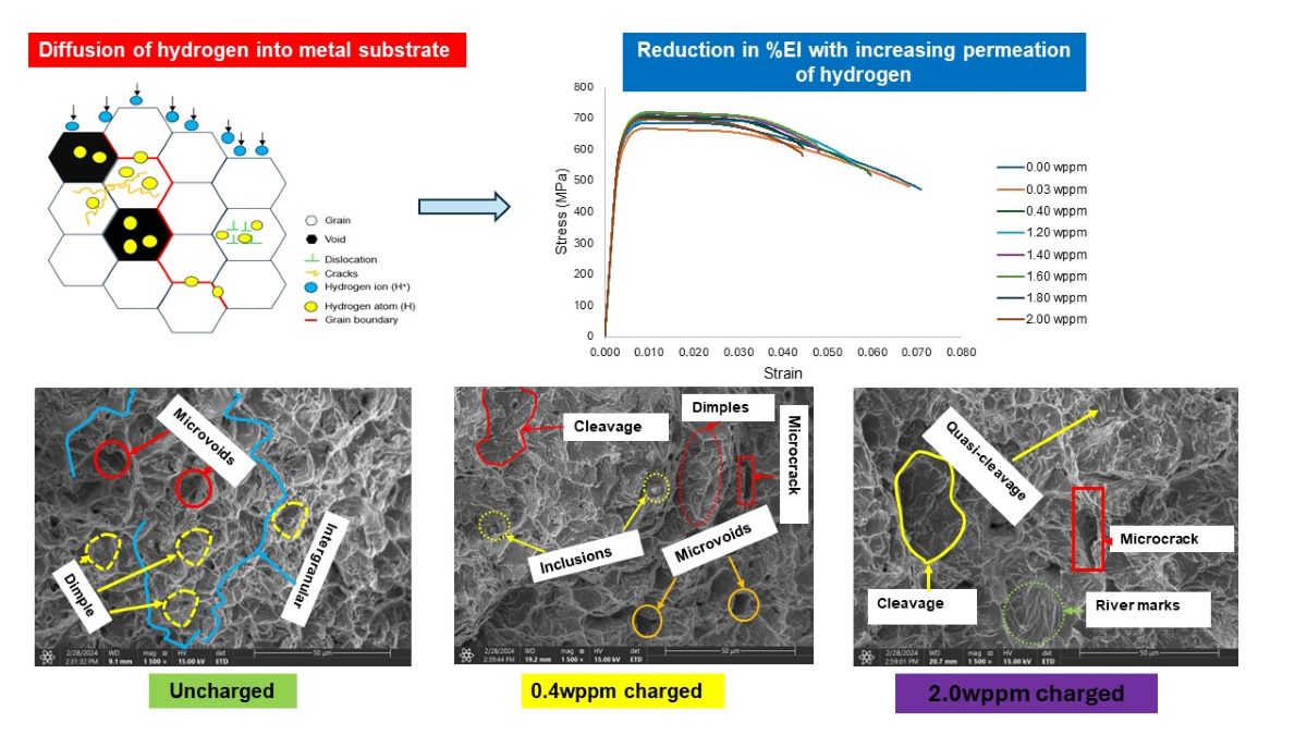
Results and findings from preceding research have indicated that hydrogen into metals reduces their fatigue strength [4,5], fracture toughness [6,7,8], and macroscopic and microscopic tensile strength [9]. Overall outcomes indicate detrimental effect on the mechanical performance of metallic structures upon the introduction of hydrogen into various traps of hydrogen as shown in Figure 1.
In the presence of hydrogen, the rate of crack propagation under cyclic loading is significantly increased. Hydrogen aids in the formation of microvoids and assists in their coalescence into cracks, which rapidly expand under repeated stress cycles. The presence of hydrogen reduces the threshold stress intensity factor (K), a measure of the stress intensity range below which fatigue crack growth does not occur [4,5]. This means that even lower stress amplitudes can lead to crack growth in hydrogen-embrittled steel, severely reducing the fatigue life [6,7]. The cumulative effect of enhanced dislocation mobility and bond weakening leads to a substantial reduction in the fatigue life of steel. This is characterized by earlier onset of fatigue crack initiation and faster crack growth rates, which collectively reduce the number of cycles the material can withstand before failure [7]. Examination of fracture surfaces in hydrogen-embrittled steel typically reveals features such as intergranular cracking, quasi-cleavage facets, and secondary cracking, which are indicative of the mechanisms.
In some steels, particularly those containing titanium or vanadium, hydrogen forms metal hydrides which are brittle and prone to cracking [8]. These hydrides precipitate at grain boundaries or within grains, creating internal stress concentrations that act as crack nucleation sites. Hydrogen atoms occupy interstitial sites in the steel’s crystal lattice, creating zones of high volumetric strain due to lattice expansion [9,10]. This local lattice distortion weakens bonds and facilitates crack initiation under tensile stress. Hydrogen-Enhanced Decohesion (HEDE) mechanism fundamentally affects the metallic bonds within the steel. Hydrogen reduces the cohesive force between iron atoms, particularly at grain boundaries [11], leading to easier separation of the grains under stress and promoting intergranular fracture [12]. The presence of hydrogen restricts the size of the plastic zone at a crack tip. Normally, the plastic zone helps to blunt the crack tip and spread the stress over a larger area, thus impeding crack growth. Hydrogen’s effect on dislocation mobility can paradoxically increase local plasticity but decrease the overall ductility of the material [13,14], leading to a sharper crack tip and enhanced crack propagation. Hydrogen can alter the typical fracture path in steel, promoting brittle fracture mechanisms such as cleavage or quasi-cleavage, instead of ductile tearing. This change in fracture mode is associated with a reduced energy absorption capacity of the material, thereby lowering its fracture toughness [15].
Reduced cohesion between metal atoms, particularly at critical stress concentrators promote crack initiation and propagation at lower stress levels than would be in non-embrittled steel can lead to both intergranular and transgranular [16] fractures, which are more brittle in nature and contribute to a lower macroscopic and microscopic tensile strength [17].
Figure 1 shows various hydrogen traps which capture and localize hydrogen atoms, intensifying their negative effects on material properties. Dislocations are linear defects in the crystal structure of metals where the regular ordering of atoms is disrupted [18]. These defects provide sites for hydrogen atoms to collect, particularly at the dislocation cores. The strain fields around dislocations increase the chemical potential for hydrogen, making these areas preferred sites for hydrogen accumulation. The accumulation of hydrogen at dislocations can significantly enhance localized plasticity, leading to the Hydrogen Enhanced Localized Plasticity (HELP) mechanism, which contributes to embrittlement. Grain boundaries, which are the interfaces between different crystalline grains, are regions of high atomic mismatch and thus have excess free volume and energy, making them favorable sites for hydrogen segregation [19,20]. Hydrogen accumulation at grain boundaries can weaken the metallic bonds at these locations, promoting intergranular cracking through the Hydrogen Enhanced Decohesion (HEDE) mechanism.
Vacancies act as effective traps for hydrogen atoms because the missing atom in the lattice creates a space into which a hydrogen atom can fit, forming a stable hydrogen-vacancy complex [21]. Hydrogen atoms trapped in vacancies can diffuse through the material, leading to the formation of hydrogen clusters that can initiate cracks or facilitate crack propagation. Microvoids and cracks can act as physical traps for hydrogen. These features can develop during manufacturing processes or due to corrosion. When hydrogen collects in these voids, it can lead to increased local pressure and stress concentration, which exacerbate crack initiation and propagation. Interfaces between different materials, such as those in multi-layered steels or coatings, can also serve as hydrogen traps. The difference in material properties across the interface creates a barrier to hydrogen diffusion, causing hydrogen to accumulate at these interfaces. The accumulation of hydrogen at material interfaces can lead to delamination or decohesion, particularly under tensile stress. Due to increased interest in lowering carbon emission by blending natural gas with hydrogen [22,23], there is a renewed interest in hydrogen embrittlement of low carbon steel, as such steels are traditionally used to transport natural gas. To achieve such a goal, more studies need to be carried out and data generated. This research seeks to establish a trend on the behavior of the tensile properties of cold finished mild steel under varying hydrogen concentrations.

2. Experimental Method

2.1. Electrochemical Charging

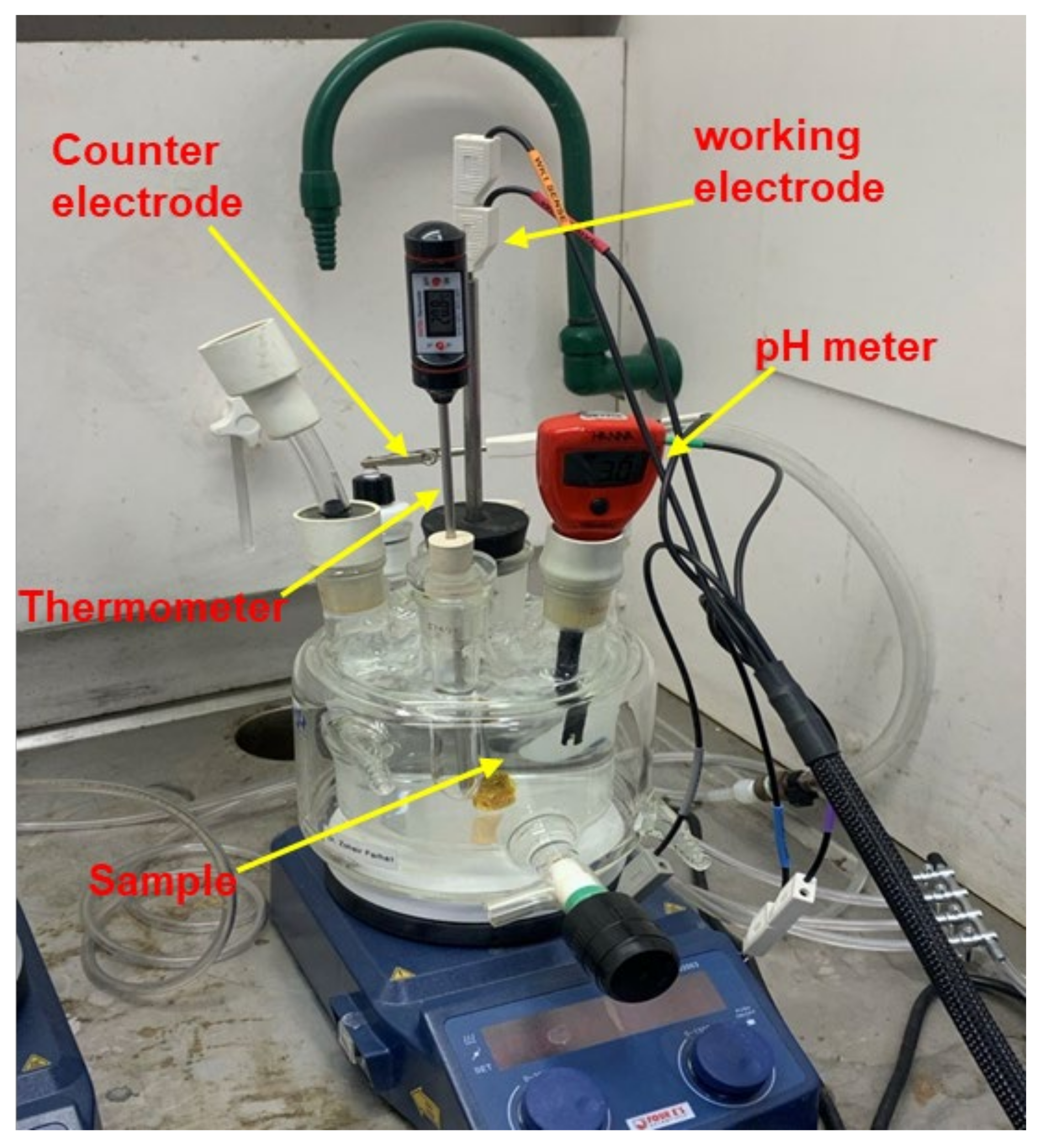
Cold finished mild steel (AISI 1018) coupons were taken through cathodic hydrogen process such that, the samples acted as cathodes. The charging cell setup used (Figure 2) had two electrodes, working and counter electrodes, whose functions were to induce a reduction reaction in the steel sample and complete the circuit to allow flow of current, respectively. A potentiostat with a maximum current capacity of 1 A was connected to supply constant current to the samples through the working electrode.
The temperature and pH of the solution (electrolyte) in the cell were determined by immersing thermometer and pH meter in the solution. The setup was connected to a computer system with software (Aftermath) in which charging parameters such as the charging time, charging current, and data collection rate were entered. The software gave a plot of current and potential against charging time. In order to ensure accuracy in outcome, all the samples had the same orientation during the charging process. The threads of the samples were masked with chemical resistant tapes to ensure that only the gauge surface area of the samples experienced charging. Prior to the charging process, the samples were cleaned with acetone to remove oil and debris from the surfaces.
Alkaline solution (NaOH) with an average pH and temperature of 11.4 and 23.1oC respectively was used as electrolyte in the charging cell. A recombination poison, ammonium thiocyanate (NH4SCN) was added to the solution to prevent hydrogen atoms from recombining into hydrogen molecules (H2). Uniformity of the solution was achieved using magnetic stirrer after which it underwent deaeration through argon purging for about 5 min.
The employed method of hydrogen diffusion (aqueous) process and charging parameters: time, charging current, and the choice of electrolyte, as well as the dissolved hydrogen, were determined from methods in a previous work [24].

2.2. Tensile Testing

In this study, samples of cold finished mild steel were used. Samples had respective surface and cross-sectional areas of 373.3mm2 and 8.6mm2. In order to have a good overview and comprehensible trend of the behavior of the samples under different hydrogen concentration conditions, 20 samples of cold finished mild steel were prepared.
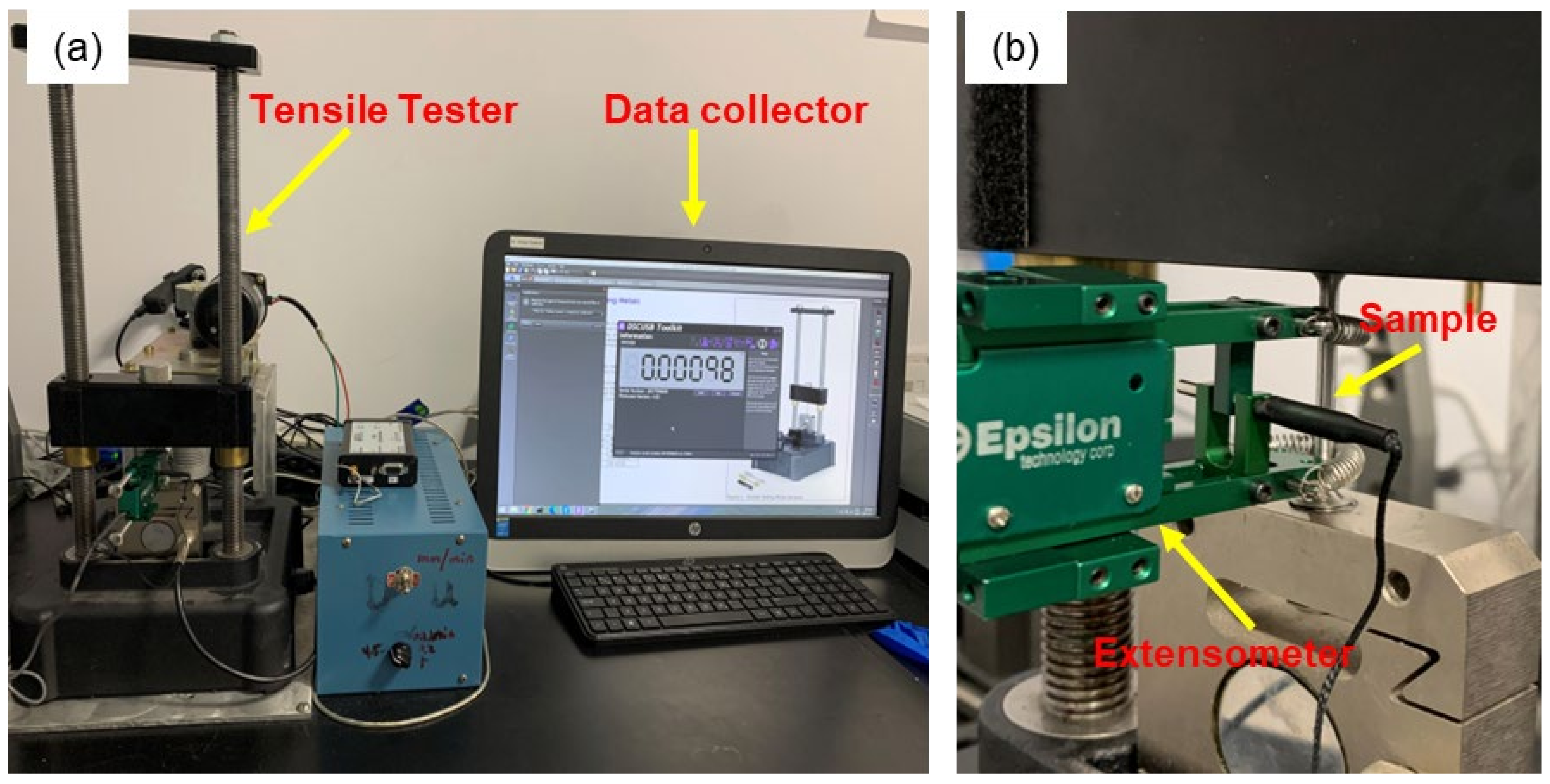
Each of the samples was subjected to uniaxial tensile testing. This was done to enable comparison of the variation in the mechanical (tensile) properties of the samples before and after charging under different conditions resulting from the diffusion of hydrogen into samples. The samples were fixed in the upper and lower grips of the tensile tester. An extensometer was connected to the gauge section of the samples to accurately measure the strain. The setup included a computer system (Figure 3) and a software package, PASCO Capstone for data collection. A tensile strain rate of 5mm/min was applied to the samples until fracture.
The samples were prepared into dog-bone shapes as shown in Figure 4, with dimensions given.

2.3. Characterization Techniques

2.3.1. Chemical Composition Analysis

To achieve the highest accuracy level possible, the chemical composition of cold finished mild steel samples was analyzed. This was done to investigate the probable presence of dissolved hydrogen in the samples possibly stemming from processing methods, preparation, storage, and transportation conditions as this could affect the outcome of the experiment.
Inductively Coupled Plasma (ICP) Spectroscopy technique was used to achieve this outcome. This technique has a multi-element capability, which allows multiple elements to be measured simultaneously in a single analysis and measures and identifies elements within a sample matrix based on the ionization of the elements within the sample.
The results obtained were compared with reported ASM standard composition for mild (low carbon) steels [25] as shown on the tables below.
Table 1. Elemental composition results obtained from ICP spectroscopy analysis.
Element Fe C Cr Mg Ni S Cu Si Mn
Composition (wt%) 98.14 0.14 0.07 0.0008 0.04 0.004 0.08 0.25 0.50
Table 2. ASM standard composition for mild (low carbon) steels [25].
Element C Si Mn
Compostion (wt%) ≤ 0.25 0.1-0.5 0.4-0.7

2.3.2. Metallography

The structure, spatial distribution of grains, voids, and inclusions as well as phases in the cold finished mild steel samples were examined. The samples were sectioned, mounted, ground, polished, and etched. After preparation, the aforementioned characteristics were observed under both scanning electron microscope and confocal microscope to aid in better analysis at low and high magnifications.
Steel samples were sectioned using slow cutting saw under well lubricated conditions to prevent microstructural alteration through heating from friction. Sectioned samples were then mounted in Bakelite.
The mounted sample was ground and polished using different grits. Grit sizes of 240, 320, 400, and 600 grit [P280, P400, P800, and P1200] were used. Following each grinding stage, the specimens were washed under running water to prevent transfer of abrasive particles to the next step to obtain a mirror-like and reflective surface free of oxidation effects required for a good microstructural examination, samples were further polished using powdered 1 micron (µm) and 0.3-micron (µm) Alumina suspension on an emery cloth, respectively.
The samples were etched by immersion in Nital for about 10 s at room temperature. Nital is a solution of nitric acid and ethanol commonly used for etching steels [26] and is especially suitable for revealing the microstructure of carbon steels. The etchant attacked and corroded the grain boundaries which produced a clear contrast between surface characteristics of the sample. The microstructural features of the sample were examined under scanning electron microscope and confocal microscope. Observations are discussed in the next section.
Rockwell hardness testing was conducted on the sample using B scale, 1 16 inch ball indentor with respective minor and major loads of 10Kg and 100Kg. Indentations were done at five different locations on the sample’s surface and the average was found. Indentation points were apart enough to alleviate the possible effect of strain hardening of one point on the hardness value of the others as well as allow full indentation without slipping.

2.3.3. X-Ray Diffraction Analysis

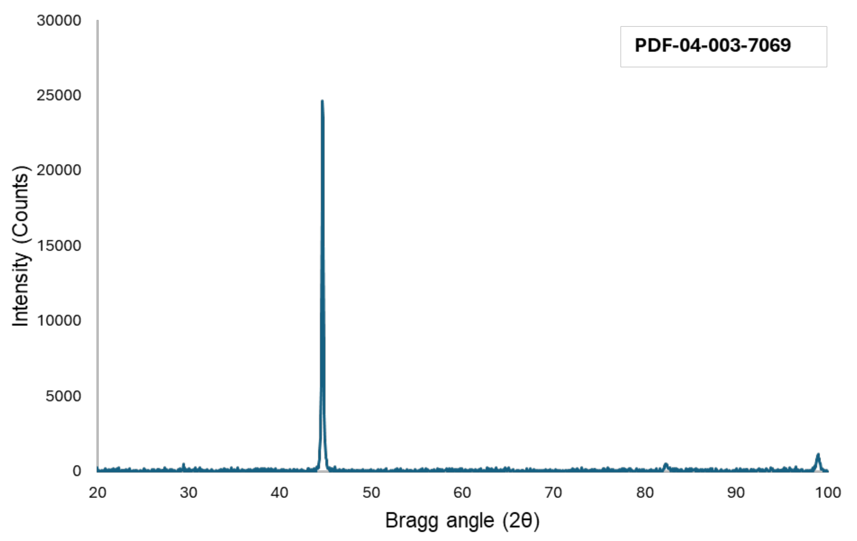
The samples of cold finished mild steel were analyzed using the X-ray diffraction technique. Portion of the sample was sectioned to a height of 2.5mm using an abrasive cutting machine. Surface of the sectioned sample was polished and cleaned. This was done using the advanced Bruker D8 Advance X-ray diffraction (XRD) system featuring a high-speed LynxEye™ detector and a copper tube, operating at 40 kV and 40 mA, and utilizing Cu Kα radiation. Samples were scanned over a 2θ range from 20° to 100° with a step size of 0.049°. The diffraction patterns obtained were analyzed with Bruker’s EVA software and compared against the International Centre for Diffraction Data (ICDD) Powder Diffraction File (PDF) database for pattern matching. The obtained diffraction pattern of this analysis is discussed below.

3. Results and Discussion

This section may be divided by subheadings. It should provide a concise and precise description of the experimental results, their interpretation, as well as the experimental conclusions that can be drawn.

3.1. Microstructure (XRD, Rockwell Hardness, Confocal, SEM)

The X-ray diffraction (XRD) pattern of the cold finished mild steel sample exhibited clearly defined Iron (Fe) peak with body-centered cubic structure suggesting that the material is crystalline as given by the Powder Diffraction File named on Figure 5 below.
Results from Rockwell hardness on five locations on the sample’s surface is shown in the table below:
Point Hardness value (HRB)
1 96.06
2 97.57
3 96.57
4 97.98
5 98.72
The sample under study has an average hardness of 97.38 HRB. A Rockwell hardness value of 97.38 HRB suggests that the mild steel samples have a significant degree of resistance to indentation or penetration by a hard object. This level of hardness is suitable for many engineering and structural applications where moderate strength and hardness are required, such as gas pipelines.
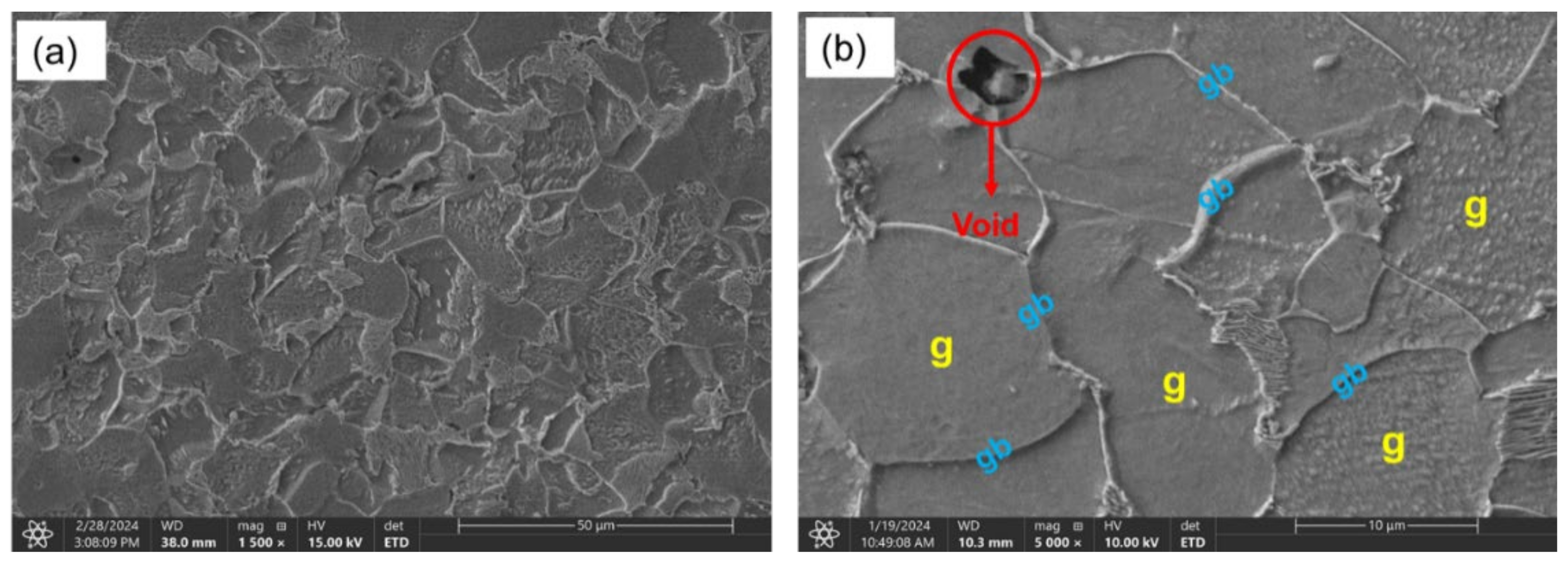
The cross-sectional surface of the polished and etched sample was analyzed under confocal microscope and scanning electron microscope for comparison at low and high magnification respectively. In both cases, the grains and grain boundaries were clearly defined with primarily ferrite and pearlite phases present as shown in Figure 6 and Figure 7 below.
The steel samples consisted of ferrite and pearlite grains of 10 µm size. Imaging from the scanning electron microscopy showed the presence of microvoids which could serve as trapping sites for induced hydrogen. Indications ‘g’ and ‘gb’ denote grains and grain boundaries respectively.

3.2. Tensile Properties

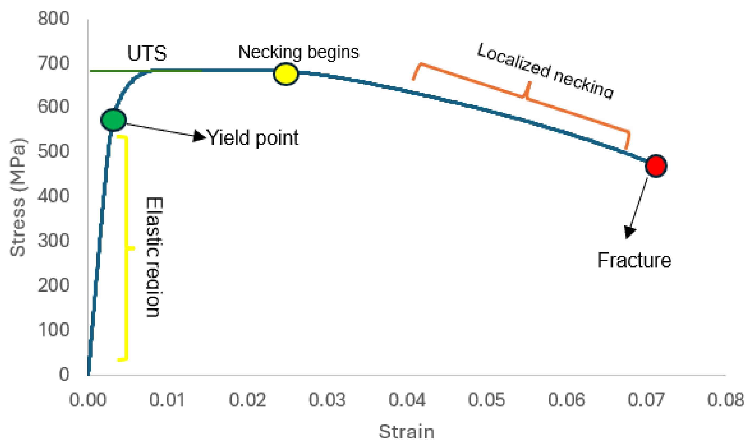
A tensile curve, used to evaluate the mechanical behavior of materials under tensile stress, describes several key segments. Initially, the elastic region shows a linear relationship between stress and strain, with the slope representing the modulus of elasticity or Young’s modulus. This phase is followed by the yield point, where the material begins to undergo plastic and permanent deformation. The curve reaches its apex at the necking and ultimate strength stage, which marks the maximum stress the material can withstand before it begins to neck and thin in a localized area. Finally, the curve plummets during the fracture or failure stage, where a sharp drop in stress indicates the material’s fracture and ultimate failure. Figure 8 below describes the discussed sections of tensile curves.
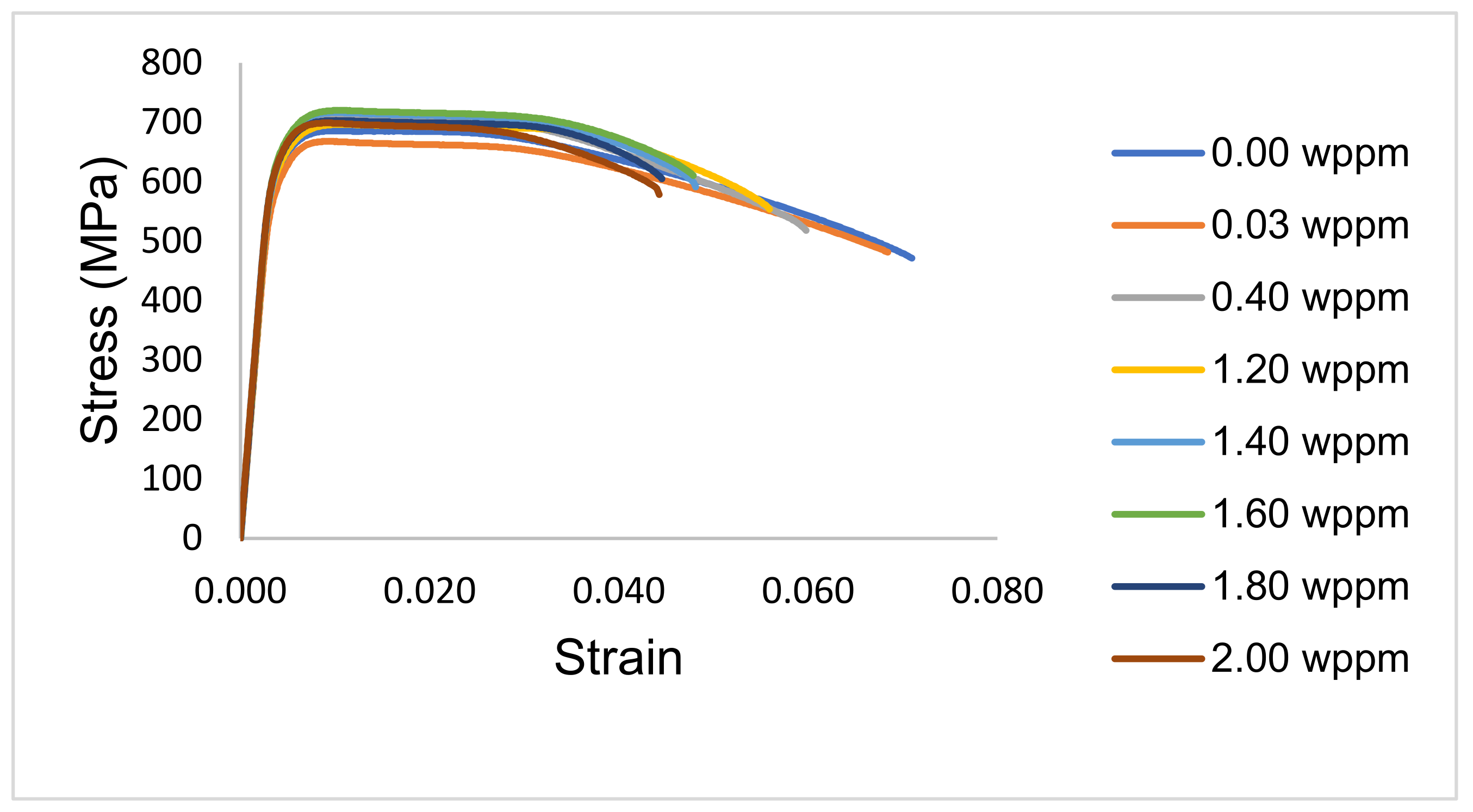
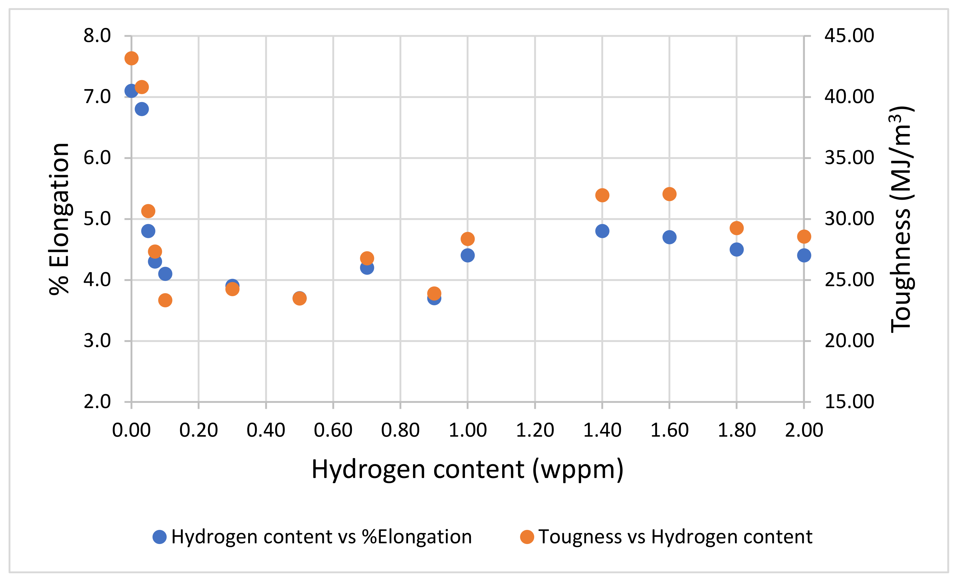
As shown in Figure 9 below, the percent elongation (ductility) and toughness of the samples decreased gradually with increasing hydrogen content from 7.1% for the uncharged sample through to 4.4% for the 2.0wppm charged sample. This occurred as a result of embrittlement from hydrogen trapping, hydrogen-enhanced decohesion, internal stress formation, and hydrogen-induced strain localization. Hydrogen atoms have a high affinity for certain defects in the metal lattice, such as dislocations, grain boundaries, and vacancies. These defects act as traps for hydrogen atoms, effectively concentrating them in localized regions within the metal. This accumulation of hydrogen atoms can lead to embrittlement by weakening the material at these specific sites, reducing its ability to deform plastically and elongate before failure.
Hydrogen atoms also weaken the atomic bonds in the metal lattice making it easier for cracks to propagate. In most cases, hydrogen does not substitute metal atoms in the lattice but occupies interstitial sites within the lattice. This introduces lattice strain due to the size difference between hydrogen and the metal atoms, leading to local distortions in the lattice structure. These distortions weaken the overall bonding within the lattice. This process, known as hydrogen-enhanced decohesion, reduces the material’s ductility and elongation by promoting premature crack initiation and propagation, even under relatively low stress levels.
As the presence of hydrogen in the metal lattice can induce internal stresses due to the size mismatch between hydrogen atoms and the metal lattice. These internal stresses can lead to the formation of microcracks and voids, which act as nucleation sites for subsequent crack propagation. As cracks propagate through the material, they reduce their ability to elongate before failure, resulting in decreased elongation.
Induced hydrogen atoms also promote strain localization in the metal lattice, a phenomenon termed Hydrogen-Induced Strain Localization [27], leading to the formation of localized regions of high stress concentration. These stress concentrations can accelerate crack initiation and propagation, further reducing the material’s elongation and ductility.
The obtained results align closely with those found by researchers [28] and [29], emphasizing the consistency and reliability of our findings in this area of study. This agreement in outcomes enhances the credibility of our individual research efforts and contributes significantly to the body of evidence supporting our shared hypotheses. This corroboration between our studies is particularly encouraging, as it paves the way for further exploration and validation of these findings within the scientific community.
The results further demonstrated a distinct correlation between elongation and toughness, as illustrated in Figure 10. Both properties displayed synchronized fluctuations, increasing, and decreasing together, which indicated a consistent pattern of behavior. This simultaneous change in elongation and toughness is indicative of a continuous degradation process, where the material exhibits an altered ductility and resistance to fracture. This trend is evidential that the material undergoes progressive embrittlement due to the continuous introduction of hydrogen into its structure. This embrittlement effect, reflected in both the elongation and toughness measurements, highlights the detrimental impact of hydrogen on the mechanical properties of the material. As aforementioned, hydrogen embrittlement occurs when hydrogen atoms diffuse into the material’s lattice, weakening its structure and making it more prone to fracture under stress. Embrittling occurs as hydrogen builds up within the material’s internal voids and microstructural defects, creating high internal pressures that can initiate and propagate cracks. A key mechanism involved is Hydrogen-Enhanced Decohesion [30], where hydrogen weakens metallic bonds at grain boundaries or interfaces, facilitating crack nucleation. Additionally, hydrogen can prompt the formation of brittle hydrides at localized sites, further contributing to embrittlement. At the tips of cracks, hydrogen adsorption is known to increase dislocation emission—a displacement of atoms within the crystal structure—exacerbating crack expansion. Collectively, these mechanisms lead to the degradation of the steel’s structural integrity, which contributes to the observed changes in both elongation and toughness behaviors.
The obtained results from this part of the study contrast with the results reported by researchers; [14] and [13] where a reduction in toughness was observed throughout the experiment. The disparity in experimental outcomes emphasizes the intricate factors influencing material behavior under hydrogen exposure. Minor variances in chemical composition or microstructure can dramatically affect mechanical performance and hydrogen interaction. Experimental variables, such as the specifics of equipment, procedures, and environmental settings like temperature and pressure, also play critical roles in divergent results. The degree of hydrogen exposure, defined by concentration and exposure time, could also add layers of variation to the data obtained. Pre-experimental history, involving any mechanical modifications or thermal processing, might have influenced various samples’ response to hydrogen permeation. Measurement discrepancies arising from different techniques and calibration standards only further emphasize the nuanced and delicate nature of assessing hydrogen’s impact on materials.
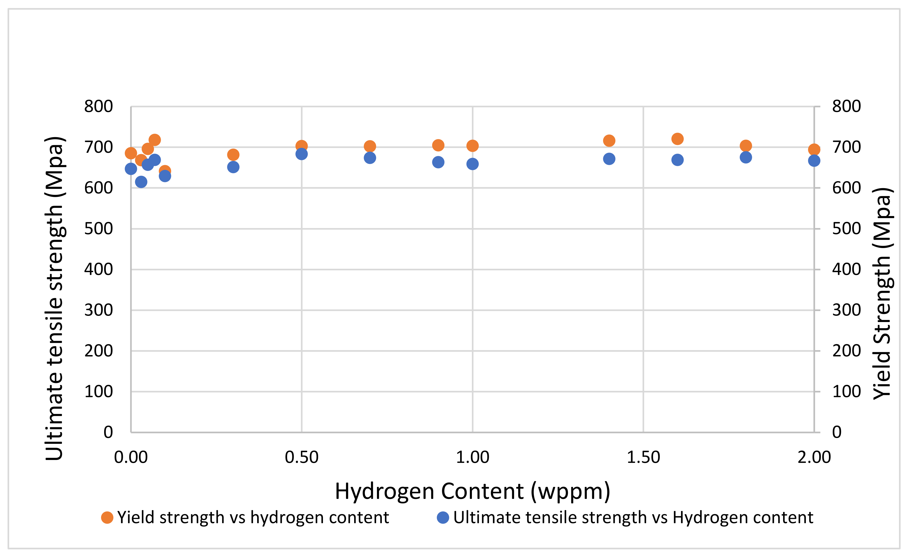
The ultimate tensile strength and yield strength of the samples exhibited minimal variation (Figure 11), demonstrating a uniform response to the applied stresses. This consistency suggests that the effects of hydrogen induction were either negligible or uniformly distributed across the samples, indicating that under the specific experimental conditions used, the hydrogen atoms did not significantly compromise the mechanical integrity of the material with respect to these properties.
Contrasting this result to that reported by [6,31], in which observed a notable reduction in both macroscopic and microscopic tensile strengths, highlights a potential divergence in the material’s response to hydrogen. This contrast suggests that factors such as an inherent resistance to hydrogen embrittlement, a potentially lower than critical hydrogen concentration, or a microstructure less susceptible to hydrogen’s adverse effects might have contributed to the observed stability in this study.
In the context of industrial applications, especially those prone to hydrogen exposure, the ability of a material to reliably maintain consistent mechanical properties is of paramount importance. This consistency ensures a high degree of safety and reliability, mitigating the risks of material failure due to property fluctuation under working conditions.
Furthermore, the constancy observed in critical mechanical properties highlights its value in substantiating theoretical predictions and enhancing the understanding of material performance in hydrogen-rich environments. These insights are vital for the design and selection of materials suited for such demanding applications, ensuring longevity and performance integrity in scenarios where hydrogen plays a pivotal role.
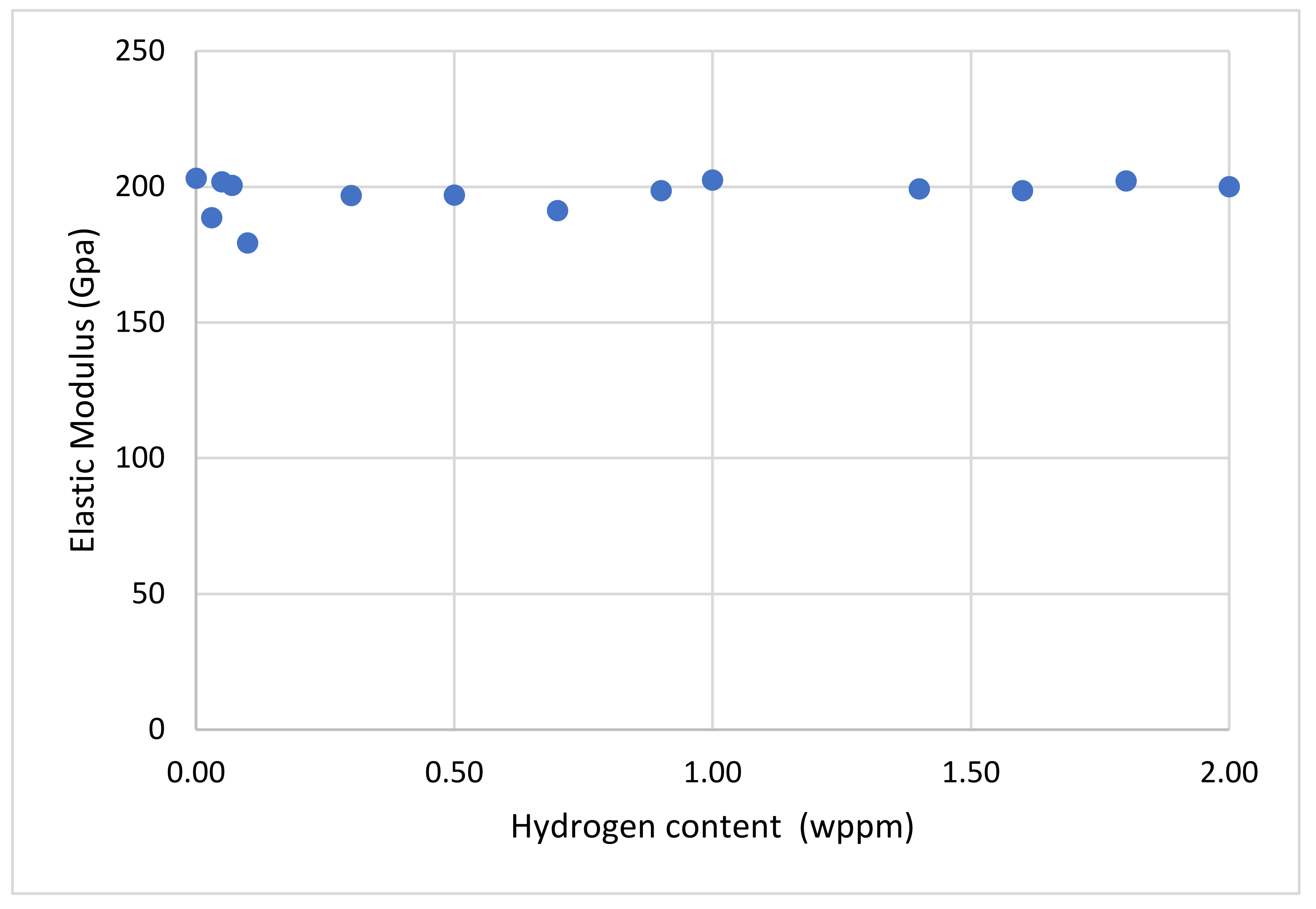
Furthermore, it was observed that the elastic modulus of the material remained consistent despite the incremental hydrogen concentration, as evidenced by the linear trend in Figure 12. This suggests that the intrinsic stiffness of the steel samples and their ability to undergo elastic deformation when subjected to stress is not significantly influenced by varying levels of hydrogen absorption. The minimal variation in the elastic modulus across different hydrogen concentrations supports the expectation that elasticity, as an inherent material property, should remain consistent, thus accounting for the negligible changes observed in the elastic modulus of the samples.
The obtained outcome of relationship between varying hydrogen content on elasticity of steel is in line with the results by [32] where study was conducted on a generally similar material, X65 pipeline steel.

3.3. Fractography

Samples’ fracture surfaces were analyzed using scanning electron microscope. Observed features are discussed below.

3.3.1. Ductile Failure (Uncharged Sample)

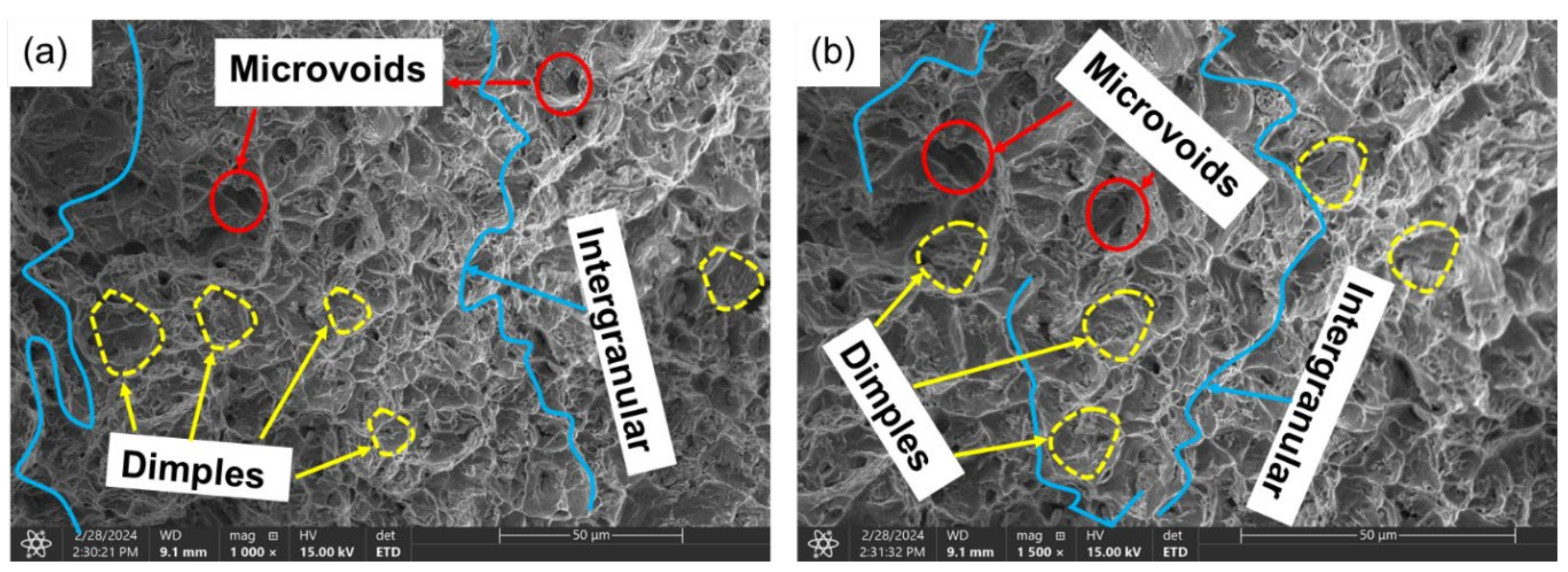
Analysis of uncharged sample yielded characteristics such as dimples, microvoids, and shear lips describing severe plastic deformation prior to fracture thus, ductile mode of failure. Microscopic inclusions, second-phase particles, or other heterogeneities within the material might have served as formation sites for microvoids. Inclusions could be impurities, precipitates, or other discontinuities in the metal matrix around which stress concentration increases under tensile loading and onset of intergranular cracks. Crack acts as a nucleation site for further crack propagation. As tensile stress is applied to the material, the crack propagated gradually, driven by the stress concentration at the crack tip. This process continued until the crack grew to a critical size.
The propagation of cracks along the grains led to the coalescence of voids leaving microscopic impressions referred to as dimples on the surfaces after failure. Also, two observably distinct macroscopic regions; the cup and the cone were created on the fractured surface. The cup central depression was characterized by a concave morphology, resembling the shape of an inverted cup and represents the area where significant plastic deformation has occurred prior to fracture. This plastic deformation results from the material’s ability to accommodate tensile stress through mechanisms such as dislocation movement.
Surrounding the cup region is the cone, which exhibits a more conical or slanted morphology. The cone region represents the area where the crack has propagated further into the material, with less plastic deformation compared to the cup region. The formation of the cone is influenced by the material’s deformation behavior and fracture toughness.
Observed dimples or depressions on surface (Figure 13) formed as adjacent grains were pulled apart indicating regions of microvoid nucleation and growth.
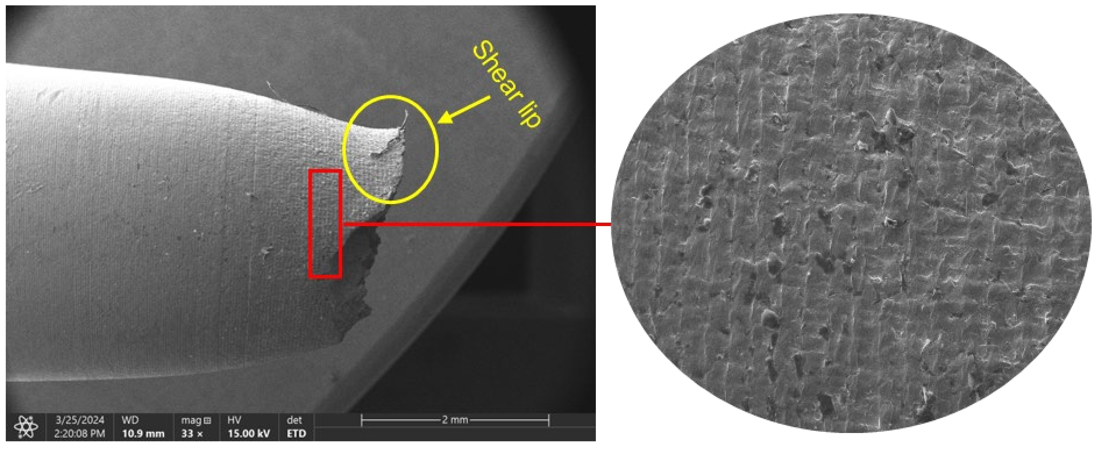
Shear lip (Figure 14) was observed along the edges of the fracture surface stemming from the reduced cross-sectional area (necking). Shear lips are raised ridges or lips that develop due to localized shear deformation near the crack tip during fracture propagation. These features indicate the dominance of shear stress components in the fracture process, often associated with plastic flow and material redistribution around the crack tip.
The surface area of the material near the failure region showed wrinkles (Figure 14) which resulted from stretching and thinning denoting that the material underwent significant plastic deformation or localized instabilities due to high tensile stresses.

3.3.2. Brittle Fracture/Failure (Charged Samples)

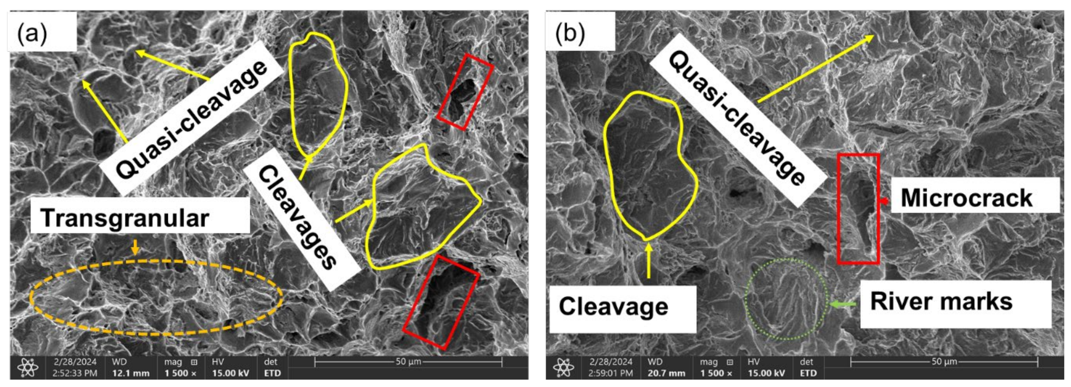
Examination of the fracture surface characteristics of samples charged with 1.2 wppm (Figure 15a) and 2.0 wppm (Figure 15b) of hydrogen revealed distinct brittle features including cleavage facets, quasi-cleavage facets, river marks, microcracks, and transgranular fracture.
As previously discussed, the presence of diffused hydrogen atoms, concentrated at stress points, can disrupt the atomic bonds within the steel matrix due to their occupation of interstitial sites within the crystal lattice. This disruption diminishes the material’s ductility and toughness, rendering regions laden with hydrogen more prone to failure as tensile stress escalates. In mild steel, hydrogen accumulation at grain boundaries instigates the formation of brittle fracture paths that traverse through the grains, rather than along the boundaries, a phenomenon termed transgranular fracture. Once initiated, cracks propagate through the grains, guided by the crystallographic structure, resulting in the formation of cleavage planes within the grains (see Figure 15).
Cleavage facets, discernible at a macroscopic level, manifest as expansive, flat, glossy surfaces perpendicular to the applied stress direction, signifying brittle fracture along specific crystallographic planes (Figure 15). Quasi-cleavage facets, resembling cleavage facets but with less distinct boundaries and possibly slight curvature, arise from localized deformation and stress concentration, rather than along predetermined crystallographic planes. They are often encountered in materials undergoing a transition from ductile to brittle behavior.
Microscopic river marks, or striations, present a unique feature distinct from macroscopic cleavage marks. These minute features, observable at a microscopic scale, manifest as parallel lines or grooves on the fracture surface, depicting the incremental advancement of the crack front as it propagates through the material. Typically perpendicular to the crack propagation direction, river marks offer insights into the fracture process at a finer resolution.
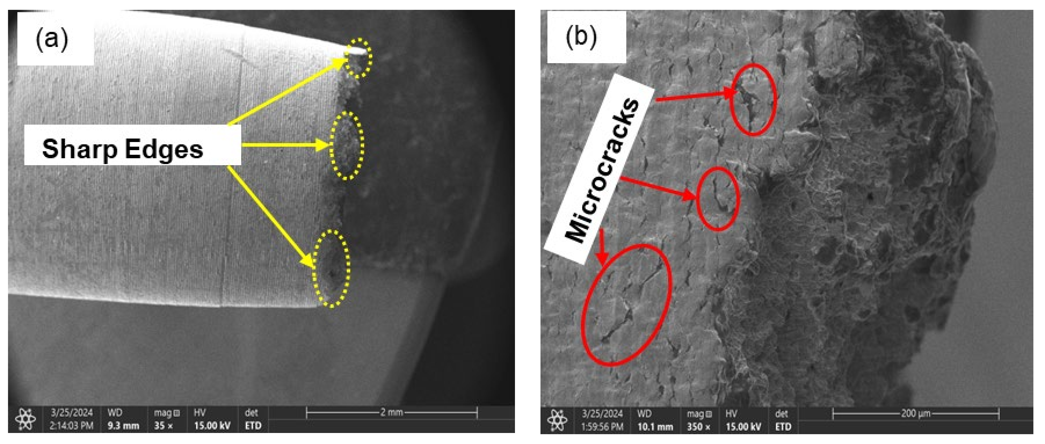
Further examination of the sample charged with 1.2 wppm hydrogen revealed evidence of microcracks (Figure 16b) adorned with sharp ridges (Figure 16a) along the edges of the cross-section, underscoring the intricate nature of the fracture process.
This observed outcome is in agreement with that obtained by researchers [33,34,35] fracture behaviors of on Mn-Ni-Mo bainitic steel, DP steel, and DP1180GI steel coils respectively under tension.
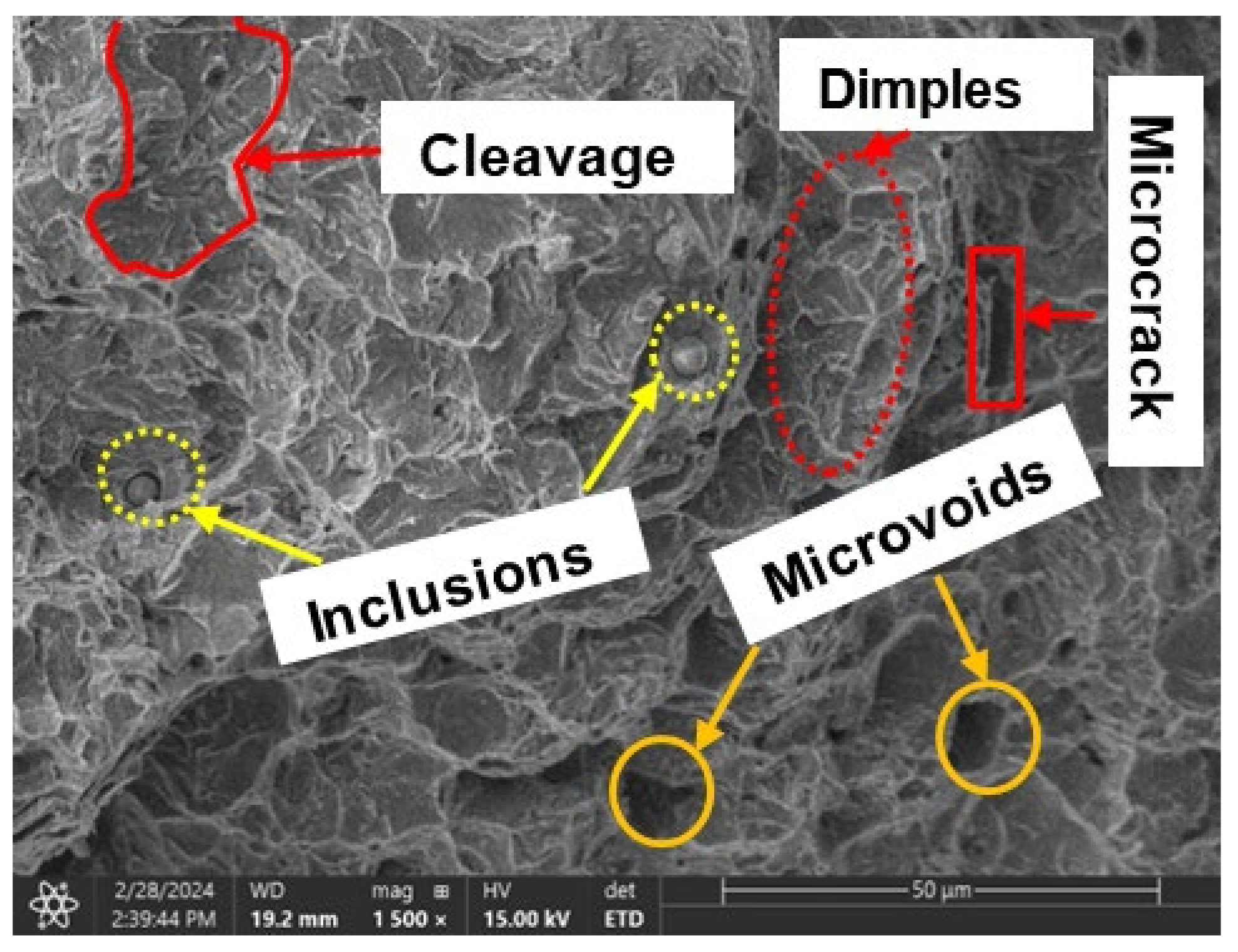
Mixed failure modes surface analysis of sample charged with relatively lower hydrogen content, displayed a mix of microscopic ductile and brittle features, as illustrated in Figure 17, where sample was charged with hydrogen content of 0.4 wppm. This combination of characteristics suggests that the charging process may have been insufficient, resulting in some degree of post-charging ductility. In addition, inclusions were observed. These inclusions act as stress concentrations due to their differing mechanical properties compared to the parent material, ultimately leading to decohesion between grains.
The mixture of properties could also stem from variations in the microstructure. Metallographic analysis revealed that the samples typically consisted of a mixture of ferrite and pearlite phases, as depicted in Figure 6 above, which can significantly affect fracture behavior. In regions with a higher proportion of ferrite, ductile features may prevail due to their inherent toughness. Conversely, areas with a higher pearlite content may exhibit more brittle behavior, especially in the presence of hydrogen embrittlement.
Moreover, the distribution of applied tensile stress conditions could influence the fracture mode. In regions experiencing higher stress concentrations, such as near defects or notch roots, brittle fracture is more likely to occur. Conversely, in areas with lower stress concentrations, the material may exhibit greater ductility before failure.

4. Conclusions

In this study, the tensile properties particularly, elongation, yield strength, ultimate tensile strength, and toughness of cold finished mild steel has been analyzed with varying hydrogen content in a simulated alkaline environment. Electrochemical hydrogen charging method employed in this study induced hydrogen into samples such that embrittling occurred as hydrogen concentration was increased through charging current. Below are some findings made from this study:
  • Sample under study had a simple microstructure primarily containing ferrite and pearlite phases with some microvoids. The stress-strain behavior of tensile testing showed a gradual reduction in the percentage elongation and toughness with increasing hydrogen content signifying embrittling from hydrogen diffusion into samples with extremities of 7.1% and 4.4% for uncharged and 2.0 wppm respectively.
  • It is evidential from the fracture surface analysis where uncharged samples showed ductile features of dimpling, microvoid coalescence, and internagranular fracture as opposed to charged samples of 1.2 wppm and 2.0 wppm which indicated embrittling with feature like cleavages, microcracks, and trangranullar fracture.
  • It was also observed that at lower hydrogen concentration levels, ie. 0.4wppm, samples showed both ductile and brittle fracture features.

Acknowledgments

This research was funded by the Natural Sciences and Engineering Research Council of Canada (NSERC), grant number RGPIN 05125-17.

References

  1. Li, X.; Ma, X.; Zhang, J.; Akiyama, E.; Wang, Y.; Song, X. Review of Hydrogen Embrittlement in Metals: Hydrogen Diffusion, Hydrogen Characterization, Hydrogen Embrittlement Mechanism and Prevention. Acta Metall. Sin.-Engl. Lett. 2020, 33, 759–773. [Google Scholar] [CrossRef]
  2. Rao, J.; Lee, S.; Dehm, G.; Duarte, M.J. Hardening Effect of Diffusible Hydrogen on BCC Fe-Based Model Alloys by in Situ Backside Hydrogen Charging. Mater. Des. 2023, 232. [Google Scholar] [CrossRef]
  3. Lu, Z.; Takeda, Y.; Shoji, T. Some Fundamental Aspects of Thermally Activated Processes Involved in Stress Corrosion Cracking in High Temperature Aqueous Environments. J. Nucl. Mater. 2008, 383, 92–96. [Google Scholar] [CrossRef]
  4. Pal, S.; Singh Raman, R.K. Determination of Threshold Stress Intensity Factor for Stress Corrosion Cracking (KISCC) of Steel Heat Affected Zone. Corros. Sci. 2009, 51, 2443–2449. [Google Scholar] [CrossRef]
  5. De Pannemaecker, A.; Fouvry, S.; Brochu, M.; Buffiere, J.Y. Identification of the Fatigue Stress Intensity Factor Threshold for Different Load Ratios R: From Fretting Fatigue to C(T) Fatigue Experiments. In Proceedings of the Int. J. Fatigue; Elsevier Ltd., January 1 2016; Vol. 82, pp. 211–225.
  6. Li, X.; Zhang, J.; Fu, Q.; Song, X.; Shen, S.; Li, Q. A Comparative Study of Hydrogen Embrittlement of 20SiMn2CrNiMo, PSB1080 and PH13-8Mo High Strength Steels; 2018;
  7. Zhang, P.; Laleh, M.; Hughes, A.E.; Marceau, R.K.W.; Hilditch, T.; Tan, M.Y. Effect of Microstructure on Hydrogen Embrittlement and Hydrogen-Induced Cracking Behaviour of a High-Strength Pipeline Steel Weldment. Corros. Sci. 2024, 227, 111764. [Google Scholar] [CrossRef]
  8. Li, X.; Liu, C.; Wang, X.; Dai, Y.; Zhan, M.; Liu, Y.; Yang, K.; He, C.; Wang, Q. Effect of Microstructure on Small Fatigue Crack Initiation and Early Propagation Behavior in Super Austenitic Stainless Steel 654SMO. Int. J. Fatigue 2024, 179. [Google Scholar] [CrossRef]
  9. Shin, J.W.; Bertocci, U.; Stafford, G.R. In Situ Stress Measurement During Hydrogen Sorption on Ultrathin (111)-Textured Pd Films in Alkaline Electrolyte. J Electrochem. Soc. 2011, 158, F127. [Google Scholar] [CrossRef]
  10. Peisl, H. 3. Lattice Strains Due to Hydrogen in Metals.
  11. Nagao, A.; Dadfarnia, M.; Somerday, B.P.; Sofronis, P.; Ritchie, R.O. Hydrogen-Enhanced-Plasticity Mediated Decohesion for Hydrogen-Induced Intergranular and “Quasi-Cleavage” Fracture of Lath Martensitic Steels. J. Mech. Phys. Solids 2018, 112, 403–430. [Google Scholar] [CrossRef]
  12. Katzarov, I.H.; Paxton, A.T. Hydrogen Embrittlement II. Analysis of Hydrogen-Enhanced Decohesion across (111) Planes in α -Fe. Phys. Rev. Mater. 2017, 1. [CrossRef]
  13. Lu, X.; Ma, Y.; Peng, D.; Johnsen, R.; Wang, D. In Situ Nanomechanical Characterization of Hydrogen Effects on Nickel-Based Alloy 725 under Different Metallurgical Conditions. J. Mater. Sci. Technol. 2023, 135, 156–169. [Google Scholar] [CrossRef]
  14. Bhuiyan, M.S.; Toda, H.; Shimizu, K.; Su, H.; Uesugi, K.; Takeuchi, A.; Watanabe, Y. The Role of Hydrogen on the Local Fracture Toughness Properties of 7XXX Aluminum Alloys. Metall. Mater. Trans. A Phys. Metall. Mater. Sci 2018, 49, 5368–5381. [Google Scholar] [CrossRef]
  15. Su, H.; Yoshimura, T.; Toda, H.; Bhuiyan, M.S.; Uesugi, K.; Takeuchi, A.; Sakaguchi, N.; Watanabe, Y. Influences of Hydrogen Micropores and Intermetallic Particles on Fracture Behaviors of Al-Zn-Mg-Cu Aluminum Alloys. Metall. Mater. Trans. A Phys. Metall. Mater. Sci 2016, 47, 6077–6089. [Google Scholar] [CrossRef]
  16. Wilson, B.T.; Robson, J.D.; Shanthraj, P.; Race, C.P. Simulating Intergranular Hydrogen Enhanced Decohesion in Aluminium Using Density Functional Theory. Model. Simul. Mat. Sci. Eng. 2022, 30. [Google Scholar] [CrossRef]
  17. New Trends and Developments in Automotive System Engineering; InTech, 2012.
  18. Zheng, S.; Qin, Y.; Li, W.; Huang, F.; Qiang, Y.; Yang, S.; Wen, L.; Jin, Y. Effect of Hydrogen Traps on Hydrogen Permeation in X80 Pipeline Steel —— a Joint Experimental and Modelling Study. Int. J. Hydrogen Energy 2023, 48, 4773–4788. [Google Scholar] [CrossRef]
  19. He, Y.; Su, Y.; Yu, H.; Chen, C. First-Principles Study of Hydrogen Trapping and Diffusion at Grain Boundaries in γ-Fe. Int. J. Hydrogen Energy 2021, 46, 7589–7600. [Google Scholar] [CrossRef]
  20. Ma, Y.; Shi, Y.; Wang, H.; Mi, Z.; Liu, Z.; Gao, L.; Yan, Y.; Su, Y.; Qiao, L. A First-Principles Study on the Hydrogen Trap Characteristics of Coherent Nano-Precipitates in α-Fe. Int. J. Hydrogen Energy 2020, 45, 27941–27949. [Google Scholar] [CrossRef]
  21. Turk, A.; Joshi, G.R.; Gintalas, M.; Callisti, M.; Rivera-Díaz-del-Castillo, P.E.J.; Galindo-Nava, E.I. Quantification of Hydrogen Trapping in Multiphase Steels: Part I – Point Traps in Martensite. Acta Mater. 2020, 194, 118–133. [Google Scholar] [CrossRef]
  22. Si, X.; Lu, R.; Zhao, Z.; Yang, X.; Wang, F.; Jiang, H.; Luo, X.; Wang, A.; Feng, Z.; Xu, J.; et al. Catalytic Production of Low-Carbon Footprint Sustainable Natural Gas. Nat. Commun. 2022, 13. [Google Scholar] [CrossRef] [PubMed]
  23. Sun, T.; Shrestha, E.; Hamburg, S.P.; Kupers, R.; Ocko, I.B. Climate Impacts of Hydrogen and Methane Emissions Can Considerably Reduce the Climate Benefits across Key Hydrogen Use Cases and Time Scales. Environ. Sci. Technol. 2023. [CrossRef] [PubMed]
  24. Li, Q.; Ghadiani, H.; Jalilvand, V.; Alam, T.; Farhat, Z.; Islam, M.A. Hydrogen Impact: A Review on Diffusibility, Embrittlement Mechanisms, and Characterization. Materials 2024, 17. [Google Scholar] [CrossRef] [PubMed]
  25. Michael Allen Adjelian Allen Rubeli Ltd., C.; Avery Consultant, H.; Babu Caterpillar, P.; Bayer Teledyne Vasco, A.M.; Boehm Nucor Steel, K.W.; Brentnall Solar Turbines, W.; Brinkman, C.; Bueche USS, E.J.; Steel Company, K.; Burrier, H.; et al. Volume 1 Publication Information and Contributors Wil Danesi Garrett Processing DivisionAllied-Signal Aerospace Company.
  26. Hanning, F.; Engelberg, D.L. Metallographic Screening of Grain Boundary Engineered Type 304 Austenitic Stainless Steel. Mater. Charact. 2014, 94, 111–115. [Google Scholar] [CrossRef]
  27. Örnek, C.; Şeşen, B.M.; Ürgen, M.K. Understanding Hydrogen-Induced Strain Localization in Super Duplex Stainless Steel Using Digital Image Correlation Technique. Met. Mater. Int. 2022, 28, 475–486. [Google Scholar] [CrossRef]
  28. Zhao, L.; Chen, H.; Zhang, C.; Wang, G.; Lu, S.; Chen, Z.; Zhao, A. Effect of Hydrogen Charging Intensities and Times on Hydrogen Embrittlement of Q&P980 Steel. Mater. Res. Express 2024, 11. [Google Scholar] [CrossRef]
  29. Wang, H.; Wang, T.; Yang, S.; Gao, J.; Yu, Y.; Tao, H. bing Ductile Burst Behavior of High Pressure X100 Steel Pipe Considering Hydrogen Damage. Int. J. Hydrogen Energy 2024, 58, 362–379. [Google Scholar] [CrossRef]
  30. Troiano, A.R. The Role of Hydrogen and Other Interstitials in the Mechanical Behavior of Metals. Metallogr. Microstruct. Anal. 2016, 5, 557–569. [Google Scholar] [CrossRef]
  31. Li, X.; Zhang, J.; Shen, S.; Wang, Y.; Song, X. Effect of Tempering Temperature and Inclusions on Hydrogen-Assisted Fracture Behaviors of a Low Alloy Steel. Materials Science and Engineering: A 2017, 682, 359–369. [Google Scholar] [CrossRef]
  32. Wang, D.; Hagen, A.B.; Wan, D.; Lu, X.; Johnsen, R. Probing Hydrogen Effect on Nanomechanical Properties of X65 Pipeline Steel Using In-Situ Electrochemical Nanoindentation. Mater. Sci. Eng.: A 2021, 824, 141819. [Google Scholar] [CrossRef]
  33. Ranjan, R.; Meena, A. Effect of Martensite-Austenite Island Decomposition during Two-Step Tempering on the Fracture Surface Morphology of Impact and Tensile Tested Mn-Ni-Mo Steel. Eng. Fail. Anal. 2024, 161. [Google Scholar] [CrossRef]
  34. Ramazani, A.; Abbasi, M.; Prahl, U.; Bleck, W. Failure Analysis of DP600 Steel during the Cross-Die Test. In Proceedings of the Comput. Mater. Sci.; November 2012; Vol. 64, pp. 101–105.
  35. Li, W.; Zhou, Y.; Zhou, Q.; Li, J. Analysis of the Delayed Cracking Mechanism of an Industrial Hot-Dip Galvanized DP1180GI Steel Coil. Eng. Fail. Anal. 2024, 160. [Google Scholar] [CrossRef]
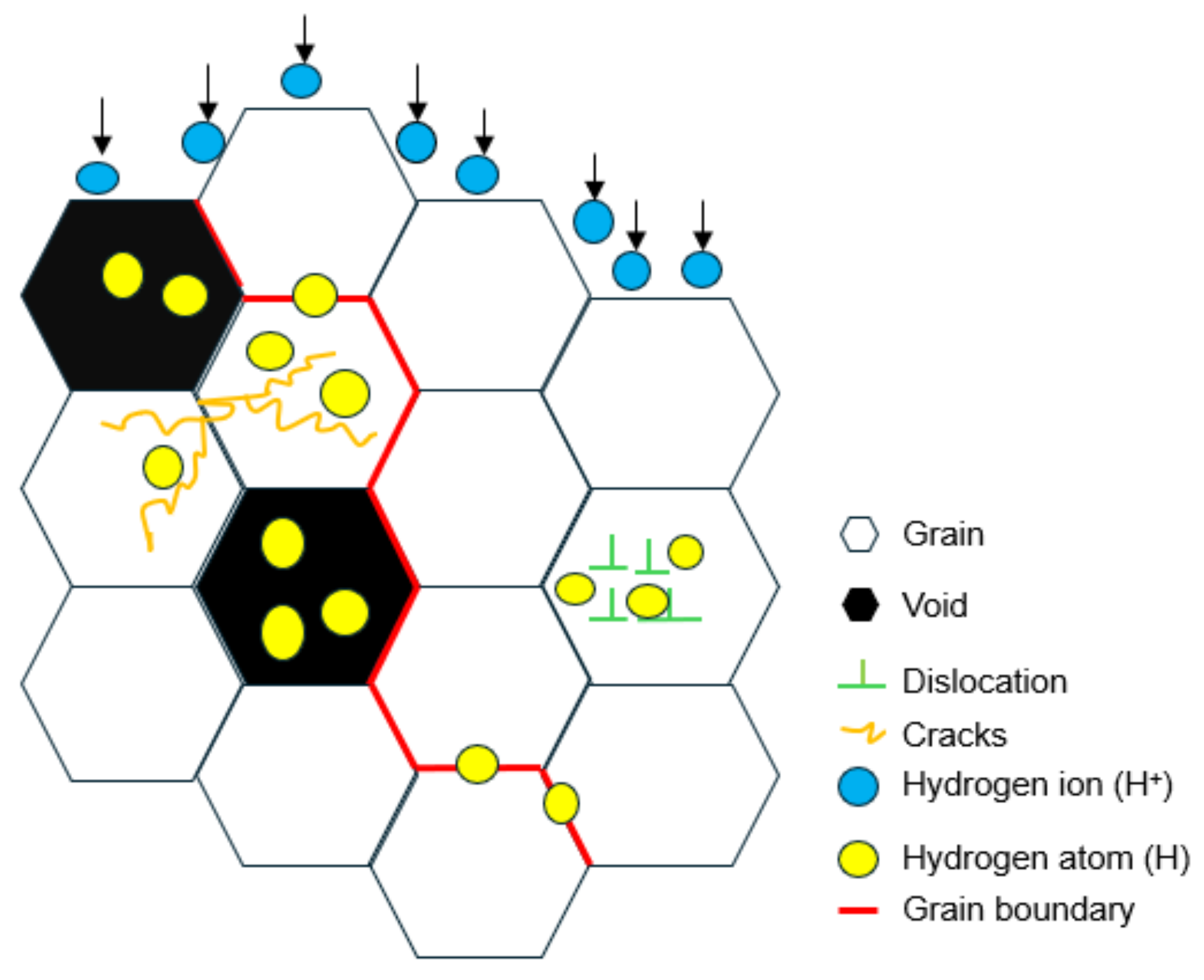
Figure 1. Schematic figure of the hydrogen diffusion process into traps of bulk alloy.
Preprints 106516 g001
Figure 2. Set up of cathodic charging process.
Preprints 106516 g002
Figure 3. (a) Tensile test set-up (b) Fitted sample in grips with an extensometer.
Preprints 106516 g003
Figure 4. (a) Schematic drawing of tensile specimen with dimensions (mm) (b) Actual tensile specimen.
Preprints 106516 g004
Figure 5. XRD patterns of Cold-finished mild steel.
Preprints 106516 g005
Figure 6. Microstructural features of etched sample under confocal microscope 20X and 50X apiece.
Preprints 106516 g006
Figure 7. SEM images of etched sample (a)1500X (b) 5000X.
Preprints 106516 g007
Figure 8. General features of a tensile curve.
Preprints 106516 g008
Figure 9. Stress-Strain Plots for Various Hydrogen Concentrations.
Preprints 106516 g009
Figure 10. % Elongation/ Toughness vs Hydrogen content.
Preprints 106516 g010
Figure 11. Ultimate tensile strength/ Yield strength vs Hydrogen content.
Preprints 106516 g011
Figure 12. Elastic Modulus vs Hydrogen Content.
Preprints 106516 g012
Figure 13. SEM images of fracture surface of samples (a) Uncharged sample-1000X (b) Uncharged sample-1500X.
Preprints 106516 g013
Figure 14. Cup and cone fracture (left) and wrinkling of surface (right).
Preprints 106516 g014
Figure 15. SEM images of (a) 1.2wppm charged (b) 2.0wppm charged.
Preprints 106516 g015
Figure 16. Sharp edges surface and microcracks on surface area (1.2wppm).
Preprints 106516 g016
Figure 17. Mixed fracture features of 0.4wppm charged sample (1500X).
Preprints 106516 g017
Disclaimer/Publisher’s Note: The statements, opinions and data contained in all publications are solely those of the individual author(s) and contributor(s) and not of MDPI and/or the editor(s). MDPI and/or the editor(s) disclaim responsibility for any injury to people or property resulting from any ideas, methods, instructions or products referred to in the content.
Copyright: This open access article is published under a Creative Commons CC BY 4.0 license, which permit the free download, distribution, and reuse, provided that the author and preprint are cited in any reuse.
Prerpints.org logo

Preprints.org is a free preprint server supported by MDPI in Basel, Switzerland.

Subscribe

© 2024 MDPI (Basel, Switzerland) unless otherwise stated