Submitted:
16 May 2024
Posted:
16 May 2024
You are already at the latest version
Abstract
Keywords:
1. Introduction
2. Materials and Methods
2.1. Prototyping
2.1.1. Overview of Prototype Exoskeleton
2.1.2. Design Elements
2.2. Experiment
2.2.1. Participants
2.2.2. Instruments
2.2.3. Procedure
2.2.4. Outcome Measures
2.2.4.1. Safety
2.2.4.2. Usability
2.2.4.3. Kinematic Parameters
2.2.5. Statistical Analysis
3. Results
3.1. Analyzed Participants
3.2. Safety Outcomes
3.3. Usability Outcomes
3.4. Kinematic Analysis Outcomes
4. Discussion
4.1. Safety and Usability
4.2. Kinematic Parameters
4.3. Proposed Design Specifications for Safety and Usability
4.4. Study Strengths and Limitations
5. Conclusions
Author Contributions
Funding
Institutional Review Board Statement
Informed Consent Statement
Acknowledgments
Conflicts of Interest
References
- Jazayeri, S.B.; Beygi, S.; Shokraneh, F.; Hagen, E.M.; Rahimi-Movaghar, V. Incidence of traumatic spinal cord injury worldwide: a systematic review. Eur Spine J. 2015, 24, 905–918. [Google Scholar] [CrossRef]
- National Spinal Cord Injury Statistical Center. Traumatic Spinal Cord Injury Facts and Figures at a Glance 2023. Birmingham, AL: University of Alabama at Birmingham; 2023. Available online: https://www.nscisc.uab.edu/public/Facts%20and%20Figures%202023%20-%20Final.pdf (accessed on 2 November 2023).
- Miyakoshi, N.; Suda, K.; Kudo, D.; Sakai, H.; Nakagawa, Y.; Mikami, Y.; Suzuki, S.; Tokioka, T.; Tokuhiro, A.; Takei, H.; Katoh, S.; Shimada, Y. A nationwide survey on the incidence and characteristics of traumatic spinal cord injury in Japan in 2018. Spinal Cord. 2021, 59, 626–634. [Google Scholar] [CrossRef]
- Japan Organization of Occupational Health and Safety, Japanese National Spinal Cord Injury Database Research Group (Ed. ). From the Treatment of Spinal Cord Injury to Social Reintegration; HOKENBUNKA-SHA: Tokyo, Japan, 2010. (in Japanese) [Google Scholar]
- Takahashi, A.; Umezaki, S. Occurrence tendency of spinal cord injuries due to work-related accidents: targeting work-related accident data. Journal of Occupational Safety and Health 2019, 12, 41–50. [Google Scholar] [CrossRef]
- Tanaka, H. Current status and issues of return to work in amputees and patients with spinal cord injury and stroke from the viewpoint of medical rehabilitation. Jpn J Rehabil Med. 2013, 50, 11–15. [Google Scholar] [CrossRef]
- Uchita, R.; Sumda, M.; Tominaga, T.; Tokuhiro, A. Return to work and employment after spinal cord injury in Japan. JJOMT. 2003, 51(3), 188–196. (in Japanese). Available online: http://www.jsomt.jp/journal/pdf/051030188.pdf (accessed on 2 November 2023).
- Chimedza, I.; Uys, K.; Shaheed, S. The impact of impairment, socio-demographic and environmental factors on spinal cord injury survivors' ability to return to work. Work 2023, 75, 461–469. [Google Scholar] [CrossRef]
- U.S. Food and Drug Administration. Product Classification. Device: powered exoskeleton. Silver Spring, MD: U.S. Food and Drug Administration; 2023. Available from: https://www.accessdata.fda.gov/scripts/cdrh/cfdocs/cfPCD/classification.cfm?ID=PHL. (accessed on 2 November 2023).
- Vukobratovic, M.; Hristic, D.; Stojiljkovic, Z. Development of active anthropomorphic exoskeletons. Med Biol Eng. 1974, 12, 66–80. [Google Scholar] [CrossRef] [PubMed]
- Yang, A.; Asselin, P.; Knezevic, S.; Kornfeld, S.; Spungen, A.M. Assessment of in-hospital walking velocity and level of assistance in a powered exoskeleton in persons with spinal cord injury. Top Spinal Cord Inj Rehabil. 2015, 21, 100–109. [Google Scholar] [CrossRef]
- Hartigan, C.; Kandilakis, C.; Dalley, S.; Clausen, M.; Wilson, E.; Morrison, S.; Etheridge, S.; Farris, R. Mobility outcomes following five training sessions with a powered exoskeleton. Top Spinal Cord Inj Rehabil. 2015, 21, 93–99. [Google Scholar] [CrossRef]
- Kozlowski, A.J.; Bryce, T. N.; Dijkers, M.P. Time and effort required by persons with spinal cord injury to learn to use a powered exoskeleton for assisted walking. Top Spinal Cord Inj Rehabil. 2015, 21, 110–121. [Google Scholar] [CrossRef]
- Federici, S; Meloni, F. ; Bracalenti, M.; De Filippis M.L. The effectiveness of powered, active lower limb exoskeletons in neurorehabilitation: A systematic review. NeuroRehabilitation 2015, 37, 321–340. [Google Scholar] [CrossRef] [PubMed]
- Miller, L.E.; Zimmermann, A.K.; Herbert, W.G. Clinical effectiveness and safety of powered exoskeleton-assisted walking in patients with spinal cord injury: systematic review with meta-analysis. Med Devices (Auckl) 2016, 9, 455–466. [Google Scholar] [CrossRef] [PubMed]
- Bhardwaj, S.; Khan, A.A.; Muzammil, M. Lower limb rehabilitation robotics: The current understanding and technology. Work 2021, 69, 775–793. [Google Scholar] [CrossRef] [PubMed]
- van Dijsseldonk, R.B.; van Nes, I.J.W; Geurts, A.C.H; Keijsers, N.L.W. Exoskeleton home and community use in people with complete spinal cord injury. Sci Rep. 2020, 10, 15600. [Google Scholar] [CrossRef] [PubMed]
- He, Y.; Eguren, D.; Luu, T.P.; Contreras-Vidal, J.L. Risk management and regulations for lower limb medical exoskeletons: a review. Med Devices (Auckl) 2017, 10, 89–107. [Google Scholar] [CrossRef] [PubMed]
- Oyama, H.; Hojo, R.; Ikeda, H. Safety and risk management of powered exoskeleton for spinal cord injury. Journal of Occupational Safety and Health 2020, 14, 15–28. [Google Scholar] [CrossRef]
- Contreras-Vidal, J.L.; A, Bhagat, N. ; Brantley, J.; Cruz-Garza, J.G.; He, Y.; Manley,Q.; Nakagome, S.; Nathan, K.; Tan, S.H.; Zhu, F.; Pons, J.L. Powered exoskeletons for bipedal locomotion after spinal cord injury. J Neural Eng. 2016, 13, 1–16. [Google Scholar] [CrossRef] [PubMed]
- Wright, M.A.; Herzog, F.; Mas-Vinyals, A.; Carnicero-Carmona, A.; Lobo-Prat, J.; Hensel, C.; Franz, S. , Weidner, N.; Vidal, J.; Opisso, E.; Rupp, R. Multicentric investigation on the safety, feasibility and usability of the ABLE lower-limb robotic exoskeleton for individuals with spinal cord injury: a framework towards the standardization of clinical evaluations. J Neuroeng Rehabil. 2023, 20, 45. [Google Scholar] [CrossRef] [PubMed]
- Miyamoto, H.; Yamazaki, T.; Sano, A.; Mori, S.; Nakazima, I.; Akamatsu, N.; Sakurai, Y. Powered orthosis for lower limbs and its clinical experiments. Journal of Life Support Technology Society 1991, 3, 108–117. [Google Scholar] [CrossRef]
- Oyama, H.; Ikeda, H. Development of a prototype powered exoskeleton for spinal cord injury. Journal of Occupational Safety and Health 2023, 16, 143–149. [Google Scholar] [CrossRef]
- Oyama, H.; Ikeda, H. Gait analysis of powered exoskeleton designed for spinal cord injury using markerless motion capture in healthy individuals. Proceedings of 70. Kongress der Gesellschaft für Arbeitswissenschaft (GfA), Stuttgart, Germany, 6–8 March 2024; 2; Ellegast, R., Ed.; GfA-Press: Sankt Augustin, Germany, ; D.5, 2024; pp. 1–6. [Google Scholar]
- Research Institute of Human Engineering for Quality Life. Japanese body size data book 2004–2006. Research Institute of Human Engineering for Quality Life: Osaka, Japan, 2011. (in Japanese).
- The Japanese Society of Rehabilitation Medicine, The Japanese Orthopaedic Association, and The Japanese Society for Surgery of the Foot. Revision of joint range of motion indicators and measurements. Jpn J Rehabil Med. 2021, 58, 1188–1200. [Google Scholar] [CrossRef]
- Kardofaki, M. Mechatronics development of a scalable exoskeleton for the lower part of a handicapped person. Thèse de doctorat de l'Université Paris-Saclay préparée à l'Université de Versailles Saint-Quentin-en-Yvelines. 2019.
- Crowell, H.P.III; Boynton, A.C.; Mungiole, M.; Exoskeleton power and torque requirements based on human biomechanics. Army research laboratory. 2002. Available online: https://apps.dtic.mil/sti/tr/pdf/ADA408684.pdf (accessed on 28 March 2024).
- Kim, S.M.; Lee, S.Y.; Kang, H.C.; Jeong, J.H. Study of knee and hip joints' moment estimation by biomechanical simulation during various motion changes. In Proceedings of The World Congress on Engineering and Computer Science 2009, San Francisco, USA, 20–22 October 2009; Ao, S.I.; Craig, D; Grundfest, W.S.; Burgstone, J. Eds.; Newswood Limited, 2009; pp. 785–788. Available online: https://www.iaeng.org/publication/WCECS2009/WCECS2009_pp785-788.pdf (accessed on 28 March 2024).
- Onen, U.; Botsali, F.M.; Kalyoncu, M.; Tinkir, M.; Yilmaz, N.; Çahin, Y. Design and actuator selection of a lower extremity exoskeleton. IEEE/ASME Transactions on Mechatronics 2014, 19, 623–632. [Google Scholar] [CrossRef]
- Götz-Neumann, K. , Gehen verstehen. Ganganalyse in der Physiotherapie [Understanding walking: Gait analysis in physiotherapy]. Georg Thieme Verlag: Stuttgart, Germany. Translated: Tsukishiro, K.; Yamamoto, S., Ehara, Y., Eds.; Bonkohara, S. [Kansatsu ni yoru hoko bunseki]. IGAKU-SHOIN: Tokyo, Japan, First Japanese edition 2005; pp. 39–75. (in Japanese) [Google Scholar]
- Wu, C.H.; Mao, H.F.; Hu, J.S.; Wang, T.Y.; Tsai, Y.J.; Hsu, W.L. The effects of gait training using powered lower limb exoskeleton robot on individuals with complete spinal cord injury. J Neuroeng Rehabil. 2018, 15, 1–10. [Google Scholar] [CrossRef] [PubMed]
- Vouga, T.; Fasola, J.; Baud, R.; Manzoori, A.R.; Pache, J.; Bouri, M.J. TWIICE One powered exoskeleton: effect of design improvements on usability in daily life as measured by the performance in the CYBATHLON race. J Neuroeng Rehabil. 2022, 19, 63–1. [Google Scholar] [CrossRef] [PubMed]
- Goffredo, M.; Romano, P.; Infarinato, F.; Cioeta, M.; Franceschini, M.; Galafate, D.; Iacopini, R.; Pournajaf, S.; Ottaviani, M. Kinematic analysis of exoskeleton-assisted community ambulation: an observational study in outdoor real-life scenarios. Sensors 2022, 22, 4533. [Google Scholar] [CrossRef]
- Teufl, W.; Miezal, M.; Taetz, B.; Fröhlich, M.; Bleser, G. Validity, test-retest reliability and long-term stability of magnetometer free inertial sensor based 3D joint kinematics. Sensors 2018, 18, 1980. [Google Scholar] [CrossRef]
- The Japanese Orthopaedic Association and The Japanese Association of Rehabilitation Medicine. Gishi sōgu no chekkuposinto, Dai 8 han [Checkpoints for Orthotics and Prosthetics, 8th ed]. IGAKU-SHOIN: Tokyo, Japan, 2020; pp. 237–239. (in Japanese).
| Specifications | Unit | |
|---|---|---|
| Weight | kg | 30 |
| Maximum torque | Nm | 90.9 |
| Maximum walking speed | km/h | 2 |
| Battery life | h | 1 |
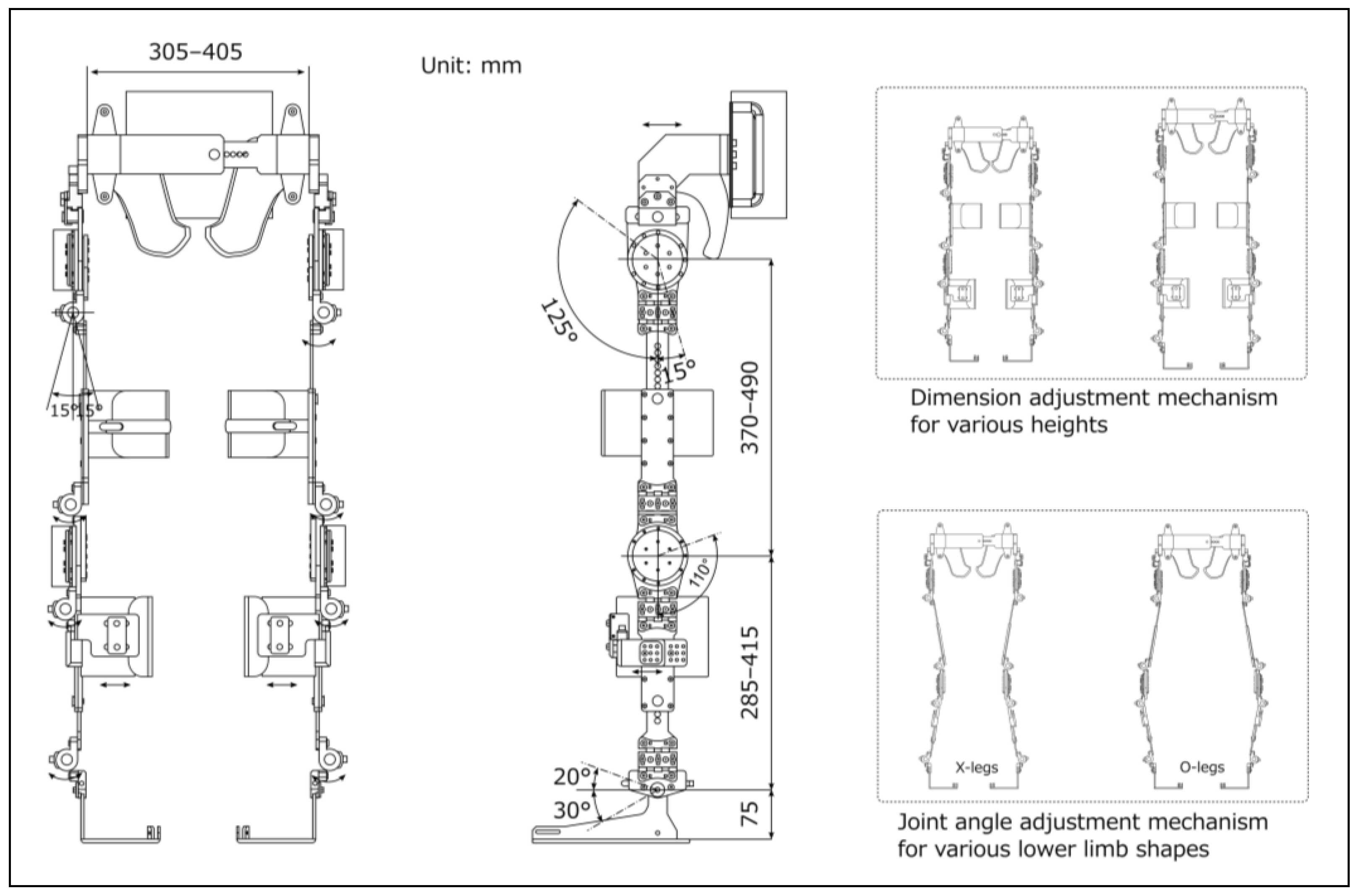
| Pelvic bandwidth | mm | 305–405 |
| Thigh length | mm | 370–490 |
| Shank length | mm | 285–415 |
| Hip flexion/extension | deg | 125/15 |
| Knee flexion | deg | 110 |
| Ankle dorsiflexion/plantar flexion | deg | 20/30 |
| Hip, knee, and ankle joint adduction/abduction | deg | 15/15 |
| Elements | Outline specifications | ReWalk | Prototype | |
|---|---|---|---|---|
| Basic functions | ||||
| Exoskeleton frame including fixture | Sufficient rigidity to support weight | ✓ | ✓ | |
| Actuator | Generate the torque required for walking and sit-standing | ✓ | ✓ | |
| Gait trigger sensor | Detect body tilt | ✓ | ✓ | |
| Computers | Control and adjust the operating parameters | ✓ | ✓ | |
| Loafstrand clutch | Maintain balance and prevent falls | ✓ | ✓ | |
| Additional functions | ||||
| Dimension adjustment mechanisms | Adjustable thigh length, shank length, and pelvic band width | ✓ | ✓ | |
| Knee guards | Prevent knee bending during standing | ✓ | ✓ | |
| Krenzak mechanism | Suppress ankle plantar flexion | ✓ | ✓ | |
| Joint angle adjustment mechanism | Fit to leg shapes (X- and O-legs) | ✓ | ||
| Gel cushioning material and hip shell | Reduce pressure, prevent skin damage | ✓ | ||
| Shoe-mounted foot segment | Easy to wear while one's shoes | ✓ | ||
| Ratchet-type clasps | Easy to don/doff | ✓ | ||
| User interface built into clutch | Easy to select operation and stop mode without changing hands | ✓ | ||
| Grip for physical therapist or caregiver | Easy to provide assistance | ✓ | ||
| Split-type structure | Easy to store and transport | ✓ | ||
| Emergency stop button | Accessible to both wearer and caregiver | ✓ | ||
Disclaimer/Publisher’s Note: The statements, opinions and data contained in all publications are solely those of the individual author(s) and contributor(s) and not of MDPI and/or the editor(s). MDPI and/or the editor(s) disclaim responsibility for any injury to people or property resulting from any ideas, methods, instructions or products referred to in the content. |
© 2024 by the authors. Licensee MDPI, Basel, Switzerland. This article is an open access article distributed under the terms and conditions of the Creative Commons Attribution (CC BY) license (http://creativecommons.org/licenses/by/4.0/).


