
You are currently viewing a beta version of our website. If you spot anything unusual, kindly let us know.
Preprint
Article
Design and Evaluation of a Powered Exoskeleton for Individuals with Spinal Cord Injury: An Experimental Study of Safety, Usability, and Kinematic Performance
Altmetrics
Downloads
149
Views
65
Comments
0


This version is not peer-reviewed
Abstract
Exoskeleton technology has been shown to be useful for individuals with spinal cord injury (SCI), potentially facilitating their recovery of motor function and social reintegration. However, studies on the safety and usability of exoskeletons are limited. This study aimed to design a powered exoskeleton for SCI and evaluate its safety and usability. Ten healthy adults participated in this study. The prototype exoskeleton featured an adjustable frame, computer-controlled hip and knee joint actuators, and a gait-trigger sensor. The experimental actions included walking, standing, and sitting, with and without the prototype. Safety outcomes included adverse events, vital signs, numerical rating scale (NRS) scores for pain, discomfort, and fatigue, and prototype-human body clearance. Usability outcomes included donning and doffing times, subjective ratings, gait speed, stride length, and kinematic parameters of hip and knee joint angles. Safety outcomes showed no serious adverse events, stable vital signs, minimal NRS scores, and acceptable clearance. Usability outcomes showed high efficiency and received positive ratings. Kinematic parameters showed significant positive correlations between normal walking and walking with the prototype for both hip and knee joint angles, confirming its effectiveness in assisting walking. However, further device improvements and gait parameter tuning are necessary for future clinical application.
Keywords:
Subject: Engineering - Bioengineering
1. Introduction
Spinal cord injury (SCI) is a traumatic event with a worldwide incidence ranging from 3.6 to 195.4 cases per million [1]. In 2023, approximately 18,000 new cases of SCI were reported in the United States [2], whereas in 2018, there were approximately 4,600 registered cases of SCI in Japan [3]. Occupational accidents accounted for 703 (28%) of the 2,515 cases documented in the Japanese National Spinal Cord Injury Database between 1997 and 2007 [4]. These occupational accidents are most common in the construction and civil engineering professions, usually resulting from falls. Recent trends indicate an increasing prevalence of SCI associated with falls in the aging population and tertiary industry activities [5]. Return-to-work rates of 13% [6] and 25% [7] have been reported, highlighting the need to improve treatment outcomes. It has also been reported that 70.6% of survivors of SCI are not reemployed, suggesting a compelling need for vocational rehabilitation services [8]. Although accident prevention is the primary focus of safety and health interventions, it is essential to emphasize measures that provide support for daily living and facilitate return to work after accidents.
SCI often results in paralysis, which may be complete, with the inability to recover lower limb function. Therefore, assistive devices, such as orthoses and wheelchairs, may become necessary for mobility. Exoskeleton technology has recently emerged as a promising solution for gait rehabilitation and mobility in patients with SCI. According to the U.S. Food and Drug Administration (FDA), a powered exoskeleton is a prescription device consisting of an external motorized orthosis placed over paralyzed or weakened lower extremities for rehabilitative purposes [9]. These devices can potentially restore locomotive function, allowing individuals with SCI to gradually reintegrate into their homes, communities, and workplaces. The use of powered exoskeletons in rehabilitation dates back to the early 1970s [10]. Advancements in digital technology have enabled the implementation of various exoskeleton models. Reports have shown promising results, especially with commercial exoskeletons such as ReWalk, Indego, and Ekso, which have undergone rigorous FDA certification testing and have helped patients with paraplegia regain walking independence [11,12,13]. Systematic [14,15] and scoping [16] reviews have further supported their clinical effectiveness. In addition, exoskeletons can potentially increase activities of daily living, both at home and in the community [17].
However, challenges exist with the use of exoskeletons, including device malfunctions, skin injuries, device misalignment, user errors, and falls [18]. Commercial exoskeletons use various strategies to reduce these challenges. For instance, they continuously supervise users in order to reduce the risk of falls. Figure 1 shows a scenario of gait rehabilitation using an exoskeleton in a clinical setting. Through hands-on assistance and monitoring, physical therapists play a crucial role in preventing patient falls using exoskeletons [19]. Further, the safety of physical therapists must be ensured as they are also at risk of falls.
Although human assistance is necessary to ensure safety, no established safety guidelines exist for exoskeleton use. These devices present technical challenges, including substantial weight, limited joint mobility, motor noise, and high cost. Overcoming these challenges requires improved technology and extensive research.
The evaluation of exoskeletons also presents several challenges. Most clinical trials focus on outcome measures such as ambulation, balance, physiological improvements, energy consumption, ease of use, and comfort [20]. However, research on the safety of exoskeletons [21] and quantitative evaluations, such as gait analysis of individuals using exoskeletons, are limited. Moreover, the accuracy of measurements may be limited by the challenges associated with conventional measurement methods. Due to the exoskeleton frame, optical motion capture systems may obscure the markers, whereas mechanical joint goniometers may experience interference from the exoskeleton.
Therefore, this study aimed to investigate the safety, usability, and kinematic performance of an exoskeleton designed for individuals with SCI. This study provides an overview of the prototype exoskeleton and presents the results of an experimental study involving healthy participants. It also proposes standard specifications to enhance the safety and usability of exoskeletons. This research provides a foundation for future clinical applications.
2. Materials and Methods
2.1. Prototyping
2.1.1. Overview of Prototype Exoskeleton
Figure 2 shows the external features of the prototype exoskeleton, and Table 1 highlights its key specifications. The primary unit consists of a structure resembling a hip-knee-ankle-foot orthosis equipped with a gait trigger sensor, a control unit, a battery, and actuators. Additionally, it includes forearm-supported clutches (Lofstrand crutches) with an operational interface and a tablet PC equipped with adjustment software.
The exoskeleton design concept prioritizes safety and user-friendliness. Its main objective is to restore the mobility of individuals with SCI to a level comparable to that of their healthy counterparts. The design was inspired by the lower-limb-powered orthosis developed by Miyamoto et al. [22], and it aligns with the FDA's definition of a medical exoskeleton [9].
We adhered to a structured schedule to implement this design concept, achieving milestones in between. In 2020, we conducted a comprehensive survey and performed a risk assessment of existing exoskeletons [19]. In 2021, we focused on engineering principles and user assistance. We developed a design concept, established requirements for the design, and created it. In 2022, we integrated an actuator and a control system into the exoskeleton structure, resulting in a functional prototype [23]. In 2023, we tested the prototype exoskeleton [24].
Our fundamental design requirements were set using the ReWalk exoskeleton (ReWalk Robotics, Inc., Yokneam, Israel) as a reference, focusing on safety and usability. Our initial criteria included height adjustments, accommodation of variations in leg alignment, ease of use, portability, overload protection, and a user-friendly interface. Input and feedback were gathered from medical doctors and physical therapists and incorporated into the design specifications.
The target users of this product are individuals with SCI at levels T4–L5 in hospitals and rehabilitation centers. These individuals experience complete paralysis of their lower extremities but have good upper limb functionality and balance. They should have a height of 145–180 cm and a weight limit of 80 kg. The exoskeleton assists individuals in walking, maintaining posture, and transitioning between sitting and standing using Lofstrand crutches. There are two classifications of exoskeleton types. One is treadmill-based, and the other is orthosis-based (overground exoskeleton), which our study focuses on. Preventing falls is a top priority. However, there are potential challenges with developing fall prevention technologies based on current capabilities, such as a predictive fall detection and control technology. A trunk-mounted harness can also reduce falls; however, practical limitations in clinical settings have led to its exclusion. Hence, this study assumed that the prevention of falls depends on traditional human support, such as contact assistance and monitoring by physical therapists.
2.1.2. Design Elements
2.1.2.1. Structure
Figure 3 shows the structural dimensions and functions of the prototype. The prototype was ergonomically designed with adjustable components and braces. These incorporated soft-padding materials to minimize the risk of skin injuries and misalignment. The structural dimensions were customized to accommodate a wide variety of individuals, ranging from the 5th percentile for adult females to the 95th percentile for adult males, based on Japanese anthropometric data [25]. This customization included a pelvic bandwidth ranging from 305 to 405 mm, thigh segment ranging from 370 to 490 mm, and shank segment ranging from 285 to 415 mm. Each segment included a sliding mechanism that could be easily secured with pin-type screws, thus simplifying the adjustments without the need for additional tools.
The joint range of motion was set according to the guidelines of the Japanese Orthopaedic Association, the Japanese Society of Rehabilitation Medicine, and the Japanese Society for Surgery of the Foot [26]. The hip joint had a range of 140°, with flexion of up to 125°, and extension of 15°. The knee joint had a range of 110° with flexion up to 110° and extension of 0°. The ankle joint had a range of 50°, with a dorsiflexion of 20° and plantar flexion of 30°. This configuration ensured the necessary ranges of motion for standing and walking. This prototype permits angle adjustments within a range of 15° in the directions of adduction and abduction of the hip, knee, and ankle joints. This feature accommodates variations in lower-limb shapes, such as the X-leg or O-leg. The design was inspired by Kardofaki's scalable exoskeleton [27]. The ankle joints include a passive mechanism inspired by the double Klenzak design to effectively limit dorsiflexion during walking. This mechanism is particularly beneficial for patients with paraplegia.
The prototype also included foldable and detachable knee guards to prevent knee flexion while standing. A gel-like material (EXGEL; Kaji Corp., Shimane, Japan) was used for the inner surfaces. The thigh braces had a large contact surface area and were equipped with a soft, 10-mm-thick urethane padding. Additionally, a three-dimensional molded resin component, called the “hip shell,” was attached to the pelvic band to conform to the contours of the pelvis. This lowered the pressure on the sacral area, reducing its susceptibility to pressure ulcers.
The foot components were designed to be shoe-mounted, allowing users to wear them over their existing footwear. Attachment to the body was done using strap belts on the waist, thighs, shanks, and feet. These belts featured ratchet-type buckles for added convenience, unlike traditional velcro closures. Additionally, a detachable handle was strategically positioned on the rear side of the pelvic band to assist physical therapists in providing support. The structural frame was primarily composed of duralumin and weighed 12.8 kg. It could be dismantled into the pelvic, thigh, shank, and foot components for easy transport and storage.
2.1.2.2. Actuator
During typical walking, the hip joint requires a maximum normalized torque of approximately 1.1 Nm/kg [28], whereas rising with arm support requires roughly 0.72 Nm/kg at the knee joint [29]. When walking with crutches, approximately 47% of the body weight is supported [30]. We assumed a maximum patient weight of 80 kg (95th percentile adult males in Japan) and an exoskeleton weight of 30 kg. Using this information, we estimated that the hip joint torque required for walking with crutches is approximately 64 Nm and the knee joint torque required for standing movements with crutches is approximately 79 Nm. Therefore, the motor torque required for the exoskeleton exceeded 79 Nm.
To satisfy this requirement, an ultra-flat actuator (model number: WPMZ-50-100-SN-3958; NIDEC Corp., Kyoto, Japan) was selected and integrated into the hip and knee joints of the frame. These actuators had a reduction gear with a 1:101 ratio. They were equipped with a brushless DC motor (rated voltage: DC48V, rated capacity: 220 W, rated rotation speed: 29.7 rpm) capable of producing a rated torque of 47 Nm and a maximum torque of 90.9 Nm. Each actuator weighed 1.1 kg, with an outer diameter of 90 mm and a thickness of 50.5 mm. This made them the slimmest and lightest actuators in their category. Despite a high reduction ratio of 1:100, they maintained excellent backdrivability (approximately 11 Nm), allowing for a manual axis drive after disengagement of the servo.
The actuator was equipped with safety features, including an integrated encoder and a dedicated motor driver (model number: FWPB4338120-48; NIDEC Corp., Kyoto, Japan) that continuously monitors and regulates the position, speed, and torque. These protective mechanisms are designed to address potential anomalies such as overcurrent, overload, and excessive speed. They also help to automatically halt the actuator whenever an overload is detected. In addition, the actuator includes software limiters and mechanical stoppers as hierarchical safety mechanisms to prevent unintended movements.
If the emergency stoppage, including automatic stoppage, is activated while walking, the hip and knee joints are locked in their respective positions, and the servos remain engaged. The servos could be deactivated by releasing the emergency stop button, allowing the exoskeleton to return to a standing position under its weight while receiving the frictional force due to backdrivability. However, it is essential to emphasize that the assistance of therapists is necessary in such situations.
2.1.2.3. Gait Trigger Sensor
A motion sensor (BWT61 Gyroscope sensor; WitMotion Co., Ltd., Shenzhen, China) for gait triggering was attached to the side of the pelvic band to account for the possibility of neuroplasticity with voluntary movement among the patients. The walking mode is activated when the user tilts their trunk forward and surpasses a predefined angle, initiating the walking sequence.
2.1.2.4. Control Unit
The control system utilizes a programmable logic controller (PLC) (KV-8000; KEYENCE Corp., Osaka, Japan) to manage functions, such as standing, walking, or sitting modes, gait triggers, walking cessation, voice-guided instructions, and abnormalities with handling. The aluminum housing on the back of the pelvic band enclosed the PLC and related components, including motor drivers and a DC48V lithium-ion battery (eBike Battery; Guangdong Greenway Technology Co., Ltd., Dongguan, China), with a combined weight of approximately 16 kg.
Figure 4 shows a flowchart of the operational program, which follows these steps: (1) The user attaches the exoskeleton while in a servo-stopped state at the origin. (2) To initiate standing movement, standing mode is selected and confirmed. (3) After a successful standing movement, each axis actuator maintains its standing position in the servo-stopped state. (4) To start walking, the user should select walking mode and then wait for the walking-start trigger. Walking is automatically initiated when the motion sensors detect a forward inclination beyond a preset angle. Pressing the walking-stop switch causes the swinging leg to return to a standing position via the shortest route in the servo-stopped state. If the sitting mode is selected, the system returns to the servo-stopped state upon completion of the sitting movement from the standing position.
Gait patterns were created using dedicated PLC software (KV COM+ for Excel, Ver. 1.4; KEYENCE Corp., Osaka, Japan). The basic gait pattern was set based on the eight gait phases set by the Rancho Los Amigos Hospital [31], with the knee and hip joint angles serving as references for typical gait in a healthy individual. In addition to joint angles, velocity, acceleration, and deceleration were considered for each gait phase. Gait was achieved by sequentially connecting the parameters.
Figure 5 shows the variations in hip and knee joint angles during the gait cycle. The vertical axis represents these joint angles, and adjustments to the flexion or extension angles can be made by modifying these values. Meanwhile, the horizontal axis represents the timeline, and the timing of flexion or extension is adjustable through modifications to velocity, acceleration, and deceleration.
The PLC memory stores a predefined basic gait pattern, allowing the autonomous operation of the exoskeleton. The predefined gait parameters were assumed to be adjusted based on the patient's condition. A user-friendly graphical interface software was developed to facilitate this process. The program can be installed on a tablet or laptop with a Windows OS. Physical therapists are thus able to use this feature to adjust the gait parameters to meet the specific clinical needs of their patients.
2.1.2.5. User Interface
This design differs from the ReWalk reference model because it allows patients to control the exoskeleton independently, eliminating the need for specialized training. This was achieved by converting a commercially available clutch grip into a versatile switch that users can operate directly. Intentional designs were incorporated to minimize the risk of user error. As highlighted in a previous study [32], the mode-selection switch was on the right grip, whereas the stop switch was on the left.
To enhance safety, an algorithm-based timed-timer function was incorporated to automatically reset the system to its initial state after a specified elapsed time period from activation of the mode-selection switch. Furthermore, the idle time was set to a minimum of 5 s, as shown in Figure 4. This feature guarantees that patients can revert to their original state even if the switch is accidentally or incorrectly activated.
In addition, the device was equipped with MP3 playback alarms and Bluetooth technology connected to the PLC, allowing for synchronized voice-guided instructions that correspond to the operational mode. When an immediate halt in operation is necessary, emergency stop can be easily accessed through switches on both the clutch grip (by long-pressing the stop button) and control unit. This enables users to initiate emergency cessation in response to anomalies or psychological distress. Exiting the emergency stop mode deactivates the servo, allowing manual adjustments of the joint angle through the therapist's assistance without significant resistance from the motor.
2.2. Experiment
This experiment aimed to evaluate the efficacy of the prototype while performing movements such as walking, standing up, and sitting down.
2.2.1. Participants
Ten healthy adults (seven males and three females) participated in this study and provided written informed consent.
2.2.2. Instruments
The experimental device used in this setup was a prototype exoskeleton. Prior to the experiment, the participants were made to familiarize themselves with the device using a custom-made walker equipped with casters. The walker was made of an aluminum frame with specific dimensions: a width of 120 cm, depth of 120 cm, and height of 212 cm.
The study employed several measuring instruments, including the Martin Anthropometer (Tsutsumi Work Inc., Chiba, Japan) for measuring human body dimensions, a caliper for measuring clearance between the human body and the exoskeleton, a Smartwatch-H2 (itDEAL; China) for heart rate monitoring, and an upper arm sphygmomanometer (Model HEM-7600T; OMRON Corp., Kyoto, Japan) for systolic and diastolic blood pressure measurements. The donning and doffing times of the exoskeleton and the walking time were recorded using a stopwatch. The experiment was performed using two digital video cameras (Model HDR-CX680; SONY Corp., Tokyo, Japan). A numerical rating scale (NRS) questionnaire was used for subjective assessments.
This study used a markerless motion capture system (e-skin MEVA; Xenoma Inc. Tokyo, Japan) to measure hip and knee joint angles. Measuring kinematic parameters with conventional methods when using exoskeletons presents challenges owing to the hiding of the marker by the exoskeleton frame in optical motion capture systems. Additionally, mechanical joint goniometers may encounter interference issues from the exoskeleton frame, which could compromise measurement accuracy. Consequently, the sensors are either integrated into the exoskeleton rotor or attached externally to the exoskeleton [33,34]. However, these approaches primarily track the movements of the exoskeleton and do not directly capture the individual motions of the wearer.
In contrast, the e-skin system has a bodysuit-type design that can be worn like clothing, ensuring minimal interference with the exoskeleton frame. The system uses an inertial measurement unit (IMU) sensor that comprises 3-axis acceleration and gyro sensors to calculate motion based on sensor data. The algorithm developed by Teufl et al. [35] enables motion calculation solely based on accelerometers and gyro sensors without relying on geomagnetism. Consequently, the system is unaffected by geomagnetic interference, which is a drawback of the IMU. This ensured stable measurements even in the presence of a motor in the exoskeleton.
The IMU sensors were positioned at 18 locations: one on the headband, ten on the upper-body shirt, and seven on the lower-body pants. The sensors were remarkably slim, measuring 20 mm in width, 35 mm in height, and 2 mm in thickness. The accelerometer had a range of ±30 G and a resolution of 16 bits, while the gyro sensor had a range of ±4000 dps and a resolution of 16 bits. Compared with optical methods, this method produces joint angle differences of only 2° with a correlation coefficient of 0.98 for the hip and knee joint angles in the sagittal plane [35]. Data were recorded at a sampling frequency of 100 Hz and transferred to a PC via Bluetooth.
2.2.3. Procedure
As part of the experimental preparation, the participants were given detailed instructions on how to operate the prototype. Vital signs were recorded, and a Martin anthropometer was used to measure their thigh lengths, lower leg lengths, and waist widths. The length and width of the exoskeleton frame were adjusted based on the respective measurements. Finally, participants donned the prototype while seated. During this process, the participants performed a standing motion to evaluate the tightness of the straps or belts with the necessary adjustments. Simultaneously, the joint angles of the left and right lower limbs were adjusted, and clearance measurements were performed. After completing this stage, the participants returned to their seats, and the prototype was removed.
The participants wore calibrated markerless motion-capture suits, and each completed two 6-meter walks at their usual pace. Joint angles were recorded using motion-capture technology, walking time was measured with a stopwatch, and frontal and side views were captured using video cameras.
The participants then donned the prototype again while seated. The time taken to don the prototype while seated was recorded using a stopwatch. The participants were trained on the use of the prototype with a specialized walker, and they practiced using crutches. The participants were allowed to choose between simultaneous bilateral or alternating thrusting motions with crutches. They were instructed not to exert force on their lower limbs while walking, sitting, or standing with the prototype. A caregiver stood behind each participant to ensure safety and prevent falls. Furthermore, air mats were placed on both sides of the walking path. Participants completed a 6-meter walk with the prototype twice. Joint angles were recorded using motion capture technology, walking time was measured with a stopwatch, and frontal and side views were captured with video cameras.
The participants also performed two sitting and standing movements using the prototype. The joint angles were continuously monitored during the movements, and side-perspective video recordings were performed. After the activities, the prototype was removed, and the time taken for doffing was measured using a stopwatch.
Finally, the participants completed the NRS questionnaires, and their vital signs were recorded. Interviews were conducted to gather comprehensive feedback. The experimental procedure lasted approximately 1.5–2 h.
2.2.4. Outcome Measures
2.2.4.1. Safety
The main objective of the safety evaluation was to assess the impact of the prototype on the participants while ensuring that there were no unexpected risks or side effects. Safety outcomes included the assessment of serious adverse events (SAEs) and adverse events (AEs) associated with device usage. The SAEs and AEs were evaluated according to the guidelines provided by ISO 14155:2011, MEDDEV 2.7/3, and MDCG 2020-10/1.
Potential adverse events were assessed by measuring the heart rate in beats per minute (bpm), systolic and diastolic blood pressures in mmHg, and oxygen saturation (SpO2) in % before and after each session. Pain and discomfort levels were evaluated using an 11-point NRS, where 0 indicated no pain or discomfort, and 10 indicated very intense pain or discomfort. Falls and physical injuries resulting from use of the device were also recorded.
The clearances between the human thigh and lower limb and the thigh and shank segments of the prototype were also measured in millimeters using calipers. This measurement evaluated compliance with the checkout criteria for lower limb orthotics, where clearance was set at approximately 5–7 mm for nonarticulated regions [36]. A narrow clearance means an increased risk of skin injuries, whereas an excessively wide clearance may lead to increased friction with clothing.
2.2.4.2. Usability
The main objective of the usability test was to evaluate the ability of the participants to operate the prototype correctly. Usability was assessed by measuring the time used by the participants in wearing and removing the device. Donning time referred to the time required to attach the strap belts to the pelvic area, thighs, shanks, and feet while the participant was in a seated position. Conversely, the doffing time was used to describe the duration required to remove the strap belts from these same locations. Additionally, a questionnaire was administered to assess the ease of donning and doffing as well as the subjective sensation of fit at three specific sites: the pelvic area, thighs, and shanks. The rating scale consisted of 11 points, aligned with the previously described NRS, ranging from 0 (difficult to don/doff) to 10 (very easy to don/doff) and from 0 (not fit) to 10 (very fit).
Gait velocity (measured in meters per second) was calculated using the walking distance and time. The stride length (measured in meters) was calculated using the walking distance and number of steps taken during walking with and without the prototype.
2.2.4.3. Kinematic Parameters
The main objective of the kinematic analysis was to verify whether the prototype functions as intended for the walking, standing, and sitting movements. The outcomes were measured using markerless motion capture. The measurement focused on the hip and knee joint angles (measured in degrees) during gait with and without the prototype, as well as during sitting and standing with the prototype.
Data from the second trial were used for gait analysis. To account for the variability in walking time among the individual participants, the joint angle data within a single gait cycle were normalized, including both the swing and stance phases, and defined as 100%. We then used the maximum (peak flexion angle) and minimum (peak extension angle) hip and knee joint angles to represent and compare the differences attributed to the exoskeleton usage.
The gait cycle was divided into eight phases, each with a specific percentage of the cycle according to the Rancho Los Amigos Hospital method: initial contact (IC) at 0%, loading response (LR) at 0–12%, mid-stance (MSt) at 12–31%, terminal stance (TSt) at 31–50%, pre-swing (PSw) at 50–62%, initial swing (ISw) at 62–75%, mid-swing (MSw) at 75–87%, and terminal swing (TSw) at 87–100% [31]. At each of these phases, stable hip and knee joint angles were extracted. The correlations between normal gait and gait with the prototype were then analyzed for these datasets.
Data from the second trial were used to analyze the standing-up motion. The analysis was divided into three segments: the initial 2 s in the seated position, the middle 3 s in the standing-up trial, and the final 2 s in the standing position. All segments were normalized to 100% for accurate representation. The analysis of the sitting-down motion followed an approach similar to that of the standing-up motion.
2.2.5. Statistical Analysis
The data are presented as mean ± standard deviation. Paired t-tests were used to compare mean vital data before and after the session. It was also used to compare gait velocity, stride length, and peak flexion/extension angles of the hip and knee joints with and without the prototype. In addition, Pearson's correlation coefficients were calculated for the hip and knee joints during a single gait cycle with and without the prototype. All statistical analyses were conducted using IBM SPSS Statistics version 28 (IBM Corp., Armonk, N.Y., USA). Statistical significance was set at p < 0.05.
3. Results
3.1. Analyzed Participants
The ten participants had the following characteristics: mean height 167 ± 10 cm (range: 152–179 cm), mean weight 58 ± 9 kg (range: 41–70 kg), and mean body mass index 21 ± 2 (range: 17–25).
3.2. Safety Outcomes
No SAEs or AEs were observed. However, a minor problem occurred while walking with the prototype; a participant lost balance and fell nearly diagonally forward to the left. Notably, the caregiver promptly intervened to prevent injury. At this point, the caregiver stopped the prototype by pressing the emergency stop switch on its back. Hence, we confirmed that an emergency arrest was performed without complications.
The mean heart rate was 74.3 ± 12.1 bpm before the session and 79.6 ± 12.5 bpm after the session. Mean systolic blood pressure was 125.0 ± 19.7 mmHg before the session and 119.8 ± 9.8 mmHg after the session, while mean diastolic blood pressure was 76.6 ± 11.8 mmHg before the session and 73.6 ± 3.0 mmHg after the session. Mean SpO2 was 97.4 ± 0.7% before the session and 97.7 ± 0.9% after the session. No significant differences were observed between the pre- and post-session measurements for any of the parameters.
The mean pain and discomfort ratings were recorded using the NRS scale as follows, respectively: pelvis area= 0.0 ± 0.0, 0.2 ± 0.7; thigh area= 0.1 ± 0.3, 0.3 ± 0.7; and lower leg area= 0.7 ± 1.1, 0.4 ± 0.7. No pain or discomfort ratings exceeded 3 during the sessions. The fatigue rating was 1.1 ± 0.8. None of the participants reported experiencing fatigue severe sufficient to make them stop the session.
The mean distance between the device and the human body was 10.2 ± 4.6 mm for the thigh and 10.9 ± 5.2 mm for the shank.
3.3. Usability Outcomes
The average time required for donning the device was 3.8 ± 0.6 min, while the mean doffing time was 0.6 ± 0.2 min. The ease of donning or doffing was reported as follows: around the pelvis= 4.8 ± 2.3; in the thigh region= 5.1 ± 2.1; and in the lower leg region= 4.7 ± 2.4.
The ratings for the feeling of fit were as follows: around the pelvis = 6.2 ± 3.0, in the thigh region = 7.0 ± 3.0, and in the lower leg region = 7.1 ± 3.0.
Participants achieved a mean gait velocity of 1.0 ± 0.1 m/s during normal walking, which decreased to 0.1 ± 0.1 m/s when using the prototype. Similarly, stride lengths were 1.2 ± 0.1 m during normal walking but decreased to 0.8 ± 0.3 m when using the prototype. Statistical analysis revealed significant differences in gait velocity (p < 0.001) and stride length (p = 0.0025) with and without the prototype.
3.4. Kinematic Analysis Outcomes
The results of the kinematic parameters of the hip and knee joints throughout the gait cycle are shown in Figure 6. Significant positive correlations were observed between normal walking and gait with prototype in both the hip joint angle (r = 0.70, p < 0.001) and the knee joint angle (r = 0.84, p < 0.001). The mean peak flexion angles of the hip joint were 30 ± 3.5° for normal walking and 30 ± 6.1° when using the prototype. The mean peak extension angles of the hip joint were -13 ± 3.7° for normal walking and -6 ± 5.1° when using the prototype. Significant differences in these parameters were observed between the two scenarios (p = 0.002). The peak flexion angles of the knee joint were 74 ± 4.5° with normal walking and 44 ± 5.2° when using the prototype, with significant differences observed between the two scenarios (p < 0.001).
Figure 7 highlights the angular changes observed in the hip and knee joints during the sit-to-standing process. The hip joint was flexed immediately before initiating the standing movement and transitioning to an extended position. Simultaneously, the knee joint shifted from a flexed to an extended posture as the participants assumed a standing position. As the participants descended from standing to sitting, the hip joint transitioned from extended to flexed, with a similar shift observed in the knee joint.
4. Discussion
This paper presents a prototype exoskeleton designed for individuals with SCI. Experiments were conducted to evaluate the safety and usability of the materials.
4.1. Safety and Usability
Although no SAEs or AEs were observed, one of the participants lost balance, but quick action was taken by the caregiver to prevent injury. This incident was related to the experimental procedure and not the device itself. However, the joint movement of the prototype is limited to one axis of flexion-extension. This feature should be particularly useful for the initial training of patients with lower limb paralysis; however, it may have been difficult for a healthy participant whose hip joints move in three dimensions during walking. Furthermore, a slower setting with abnormal walking patterns may have contributed to this event. Furthermore, human factors, such as learning forward while using crutches and inadequate training, may have played a role. These findings highlight the need for additional device enhancements and user training to ensure participant safety.
No significant differences were observed in the vital signs before and after the experiment. The subjective pain, discomfort, and fatigue ratings were minimal, with no session interruption. Therefore, it can be inferred that the health risks associated with exoskeleton use are low. The mean clearance between the thigh and lower leg was 10 mm. Compared with the criteria for lower-limb orthotics, the clearance values of the prototype are slightly larger but still within a reasonable range. The subjective fit ratings consistently indicated high levels of comfort in all areas. The ergonomic approach of combining adjustable structures and soft materials within a brace effectively minimizes skin problems and misalignment, as evidenced by the low pain and discomfort ratings. These results could also benefit physical therapists via the potential of eliminating traditional tasks, such as applying and removing pads, thereby streamlining the preparation process in clinical settings.
The time required to don and doff the device was reasonable, and subjective ratings of the ease of donning and doffing suggested the process was relatively straightforward. Conversely, according to a previous study, it took approximately 7 min to don and 2 min to doff the conventional device (ReWalk) [19]. It is important to note that these time durations include the time used in applying and removing the pads to prevent skin abrasions; therefore, it is difficult to make direct comparisons. However, our prototype successfully had lower donning and doffing times. This improvement was due to the switch from the traditional velcro system to the ratchet system, allowing for easy adjustment, secure attachment, and quick, one-touch removal.
4.2. Kinematic Parameters
We found that the prototype successfully executed the intended walking, standing, and sitting programs. The kinematic results during walking indicate nearly identical hip and knee joint patterns with and without the prototype, proving that the prototype provides gait assistance.
However, significant differences were observed in the peak values of the knee joint flexion angle and hip joint extension angle. During the stance phase of walking with the prototype, the knee was inadequately flexed, particularly during the weight response phase. In addition, the maximum angle of knee flexion during the swing phase was smaller than that during normal walking. Furthermore, the maximum hip extension angle with the prototype was smaller than that during normal walking. On observation, it appears like the foot makes ground contact before the knee fully extends and that there is a forward-leaning posture owing to the use of crutches. These factors may be related to the shorter stride length of the prototype compared to normal walking. Therefore, adjusting the settings of the prototype's walking program will be necessary in the future.
In addition, the mean gait velocity achieved with the prototype was only 10% of that in normal walking. This was because the participants were using the exoskeleton for the first time, and some expressed apprehension about going faster. Hence, the speed of the exoskeleton was intentionally set to a slow pace to improve safety. According to the opinion of a physical therapist with experience in using exoskeletons, the speed is usually initially set to slower, although faster speeds make walking more stable. As the prototype's specifications allow it to reach speeds of up to 0.5 m/s, equivalent to that of a conventional exoskeleton, it will be necessary to gradually adjust the speed according to the user's condition and proficiency level.
4.3. Proposed Design Specifications for Safety and Usability
As shown in Table 2, based on the results of the evaluation experiments, we can propose design specifications for an exoskeleton for individuals with SCI, considering safety and usability. The table also includes a comparison with conventional ReWalk products. The prototype incorporates unique features such as joint angle adjustment mechanisms, gel-type cushioning material, hip shells, and modularity, while still maintaining basic functionality equivalent to that of conventional products, including the ability to assist with walking, standing, and sitting. These additions were designed to enhance safety and usability.
4.4. Study Strengths and Limitations
A major strength of this study is that we developed a novel exoskeleton for individuals with SCI and quantitatively measured subtle body movements within the exoskeleton frame using a markerless motion capture system, which was previously considered difficult. Our results provide strong evidence that the prototype can successfully perform walking, standing, and sitting movements when worn by healthy participants. This performance suggests that the prototype has properties similar to conventional exoskeletons and can potentially improve the walking ability of individuals with SCI. In addition, the prototype exoskeleton effectively addressed common problems associated with the use of exoskeletons, including skin injuries and misalignment. Key features, such as adjustable dimensions and joint angles, cushioning materials, ratcheting fasteners, and a wireless operating interface built in to the clutch, improve the safety and usability of the exoskeleton.
However, this study has some limitations which must be acknowledged. We used a small sample size and relatively short experimental duration, which could have introduced some bias into our findings. This could be addressed by expanding the study to include more participants and longer-term investigations. In addition, there were technical challenges, particularly with the weight of the prototype, which exceeds that of conventional devices. Lightweight materials such as carbon fibers, battery capacity adjustments, and a specially designed control system instead of a general-purpose PLC could be explored to achieve the desired weight target. Adjusting gait parameters based on normal gait data and reevaluating the basic gait pattern are also necessary. Given these limitations, it is imperative to continue improving and adapting the prototype. It is essential to comprehensively evaluate patients with SCI in clinical settings to better understand the prototype and its potential applications.
5. Conclusions
A prototype exoskeleton was designed for individuals with SCI. Experimental evaluations with healthy participants showed good safety and usability of the device. In addition, it demonstrated the ability to facilitate walking, standing, and sitting movements. However, further improvement of the device and adjustment of gait parameters are essential to improve its application in future clinical settings.
Author Contributions
Conceptualization, H.O. and H.I.; methodology, H.O. and H.I.; validation, H.O. and H.I.; formal analysis, H.O.; investigation, H.O. and H.I.; data curation, H.O.; writing—original draft preparation, H.O.; writing—review and editing, H.O. and H.I.; visualization, H.O. All authors have read and agreed to the published version of the manuscript.
Funding
This research received no external funding.
Institutional Review Board Statement
This study was approved by the Ethics Committee of the Japan Organization of Occupational Health and Safety (reference number: 2022-17).
Informed Consent Statement
The participants provided their written informed consent to participate in this study.
Acknowledgments
The authors thank Dr. Kazunari Furusawa and Mr. Yoshinori Yamada for their valuable advice and the medical staff of Kibi Kogen Rehabilitation Center for their cooperation. They also thank Arcelis Inc. for their cooperation in manufacturing the structural frame for prototype development, and Altech Corp. and Digital Spice Corp. for their cooperation in manufacturing the control system.
Conflicts of Interest
The authors have no potential conflicts of interest to report.
References
- Jazayeri, S.B.; Beygi, S.; Shokraneh, F.; Hagen, E.M.; Rahimi-Movaghar, V. Incidence of traumatic spinal cord injury worldwide: a systematic review. Eur Spine J. 2015, 24, 905–918. [Google Scholar] [CrossRef]
- National Spinal Cord Injury Statistical Center. Traumatic Spinal Cord Injury Facts and Figures at a Glance 2023. Birmingham, AL: University of Alabama at Birmingham; 2023. Available online: https://www.nscisc.uab.edu/public/Facts%20and%20Figures%202023%20-%20Final.pdf (accessed on 2 November 2023).
- Miyakoshi, N.; Suda, K.; Kudo, D.; Sakai, H.; Nakagawa, Y.; Mikami, Y.; Suzuki, S.; Tokioka, T.; Tokuhiro, A.; Takei, H.; Katoh, S.; Shimada, Y. A nationwide survey on the incidence and characteristics of traumatic spinal cord injury in Japan in 2018. Spinal Cord. 2021, 59, 626–634. [Google Scholar] [CrossRef]
- Japan Organization of Occupational Health and Safety, Japanese National Spinal Cord Injury Database Research Group (Ed. ). From the Treatment of Spinal Cord Injury to Social Reintegration; HOKENBUNKA-SHA: Tokyo, Japan, 2010. (in Japanese) [Google Scholar]
- Takahashi, A.; Umezaki, S. Occurrence tendency of spinal cord injuries due to work-related accidents: targeting work-related accident data. Journal of Occupational Safety and Health 2019, 12, 41–50. [Google Scholar] [CrossRef]
- Tanaka, H. Current status and issues of return to work in amputees and patients with spinal cord injury and stroke from the viewpoint of medical rehabilitation. Jpn J Rehabil Med. 2013, 50, 11–15. [Google Scholar] [CrossRef]
- Uchita, R.; Sumda, M.; Tominaga, T.; Tokuhiro, A. Return to work and employment after spinal cord injury in Japan. JJOMT. 2003, 51(3), 188–196. (in Japanese). Available online: http://www.jsomt.jp/journal/pdf/051030188.pdf (accessed on 2 November 2023).
- Chimedza, I.; Uys, K.; Shaheed, S. The impact of impairment, socio-demographic and environmental factors on spinal cord injury survivors' ability to return to work. Work 2023, 75, 461–469. [Google Scholar] [CrossRef]
- U.S. Food and Drug Administration. Product Classification. Device: powered exoskeleton. Silver Spring, MD: U.S. Food and Drug Administration; 2023. Available from: https://www.accessdata.fda.gov/scripts/cdrh/cfdocs/cfPCD/classification.cfm?ID=PHL. (accessed on 2 November 2023).
- Vukobratovic, M.; Hristic, D.; Stojiljkovic, Z. Development of active anthropomorphic exoskeletons. Med Biol Eng. 1974, 12, 66–80. [Google Scholar] [CrossRef] [PubMed]
- Yang, A.; Asselin, P.; Knezevic, S.; Kornfeld, S.; Spungen, A.M. Assessment of in-hospital walking velocity and level of assistance in a powered exoskeleton in persons with spinal cord injury. Top Spinal Cord Inj Rehabil. 2015, 21, 100–109. [Google Scholar] [CrossRef]
- Hartigan, C.; Kandilakis, C.; Dalley, S.; Clausen, M.; Wilson, E.; Morrison, S.; Etheridge, S.; Farris, R. Mobility outcomes following five training sessions with a powered exoskeleton. Top Spinal Cord Inj Rehabil. 2015, 21, 93–99. [Google Scholar] [CrossRef]
- Kozlowski, A.J.; Bryce, T. N.; Dijkers, M.P. Time and effort required by persons with spinal cord injury to learn to use a powered exoskeleton for assisted walking. Top Spinal Cord Inj Rehabil. 2015, 21, 110–121. [Google Scholar] [CrossRef]
- Federici, S; Meloni, F. ; Bracalenti, M.; De Filippis M.L. The effectiveness of powered, active lower limb exoskeletons in neurorehabilitation: A systematic review. NeuroRehabilitation 2015, 37, 321–340. [Google Scholar] [CrossRef] [PubMed]
- Miller, L.E.; Zimmermann, A.K.; Herbert, W.G. Clinical effectiveness and safety of powered exoskeleton-assisted walking in patients with spinal cord injury: systematic review with meta-analysis. Med Devices (Auckl) 2016, 9, 455–466. [Google Scholar] [CrossRef] [PubMed]
- Bhardwaj, S.; Khan, A.A.; Muzammil, M. Lower limb rehabilitation robotics: The current understanding and technology. Work 2021, 69, 775–793. [Google Scholar] [CrossRef] [PubMed]
- van Dijsseldonk, R.B.; van Nes, I.J.W; Geurts, A.C.H; Keijsers, N.L.W. Exoskeleton home and community use in people with complete spinal cord injury. Sci Rep. 2020, 10, 15600. [Google Scholar] [CrossRef] [PubMed]
- He, Y.; Eguren, D.; Luu, T.P.; Contreras-Vidal, J.L. Risk management and regulations for lower limb medical exoskeletons: a review. Med Devices (Auckl) 2017, 10, 89–107. [Google Scholar] [CrossRef] [PubMed]
- Oyama, H.; Hojo, R.; Ikeda, H. Safety and risk management of powered exoskeleton for spinal cord injury. Journal of Occupational Safety and Health 2020, 14, 15–28. [Google Scholar] [CrossRef]
- Contreras-Vidal, J.L.; A, Bhagat, N. ; Brantley, J.; Cruz-Garza, J.G.; He, Y.; Manley,Q.; Nakagome, S.; Nathan, K.; Tan, S.H.; Zhu, F.; Pons, J.L. Powered exoskeletons for bipedal locomotion after spinal cord injury. J Neural Eng. 2016, 13, 1–16. [Google Scholar] [CrossRef] [PubMed]
- Wright, M.A.; Herzog, F.; Mas-Vinyals, A.; Carnicero-Carmona, A.; Lobo-Prat, J.; Hensel, C.; Franz, S. , Weidner, N.; Vidal, J.; Opisso, E.; Rupp, R. Multicentric investigation on the safety, feasibility and usability of the ABLE lower-limb robotic exoskeleton for individuals with spinal cord injury: a framework towards the standardization of clinical evaluations. J Neuroeng Rehabil. 2023, 20, 45. [Google Scholar] [CrossRef] [PubMed]
- Miyamoto, H.; Yamazaki, T.; Sano, A.; Mori, S.; Nakazima, I.; Akamatsu, N.; Sakurai, Y. Powered orthosis for lower limbs and its clinical experiments. Journal of Life Support Technology Society 1991, 3, 108–117. [Google Scholar] [CrossRef]
- Oyama, H.; Ikeda, H. Development of a prototype powered exoskeleton for spinal cord injury. Journal of Occupational Safety and Health 2023, 16, 143–149. [Google Scholar] [CrossRef]
- Oyama, H.; Ikeda, H. Gait analysis of powered exoskeleton designed for spinal cord injury using markerless motion capture in healthy individuals. Proceedings of 70. Kongress der Gesellschaft für Arbeitswissenschaft (GfA), Stuttgart, Germany, 6–8 March 2024; 2; Ellegast, R., Ed.; GfA-Press: Sankt Augustin, Germany, ; D.5, 2024; pp. 1–6. [Google Scholar]
- Research Institute of Human Engineering for Quality Life. Japanese body size data book 2004–2006. Research Institute of Human Engineering for Quality Life: Osaka, Japan, 2011. (in Japanese).
- The Japanese Society of Rehabilitation Medicine, The Japanese Orthopaedic Association, and The Japanese Society for Surgery of the Foot. Revision of joint range of motion indicators and measurements. Jpn J Rehabil Med. 2021, 58, 1188–1200. [Google Scholar] [CrossRef]
- Kardofaki, M. Mechatronics development of a scalable exoskeleton for the lower part of a handicapped person. Thèse de doctorat de l'Université Paris-Saclay préparée à l'Université de Versailles Saint-Quentin-en-Yvelines. 2019.
- Crowell, H.P.III; Boynton, A.C.; Mungiole, M.; Exoskeleton power and torque requirements based on human biomechanics. Army research laboratory. 2002. Available online: https://apps.dtic.mil/sti/tr/pdf/ADA408684.pdf (accessed on 28 March 2024).
- Kim, S.M.; Lee, S.Y.; Kang, H.C.; Jeong, J.H. Study of knee and hip joints' moment estimation by biomechanical simulation during various motion changes. In Proceedings of The World Congress on Engineering and Computer Science 2009, San Francisco, USA, 20–22 October 2009; Ao, S.I.; Craig, D; Grundfest, W.S.; Burgstone, J. Eds.; Newswood Limited, 2009; pp. 785–788. Available online: https://www.iaeng.org/publication/WCECS2009/WCECS2009_pp785-788.pdf (accessed on 28 March 2024).
- Onen, U.; Botsali, F.M.; Kalyoncu, M.; Tinkir, M.; Yilmaz, N.; Çahin, Y. Design and actuator selection of a lower extremity exoskeleton. IEEE/ASME Transactions on Mechatronics 2014, 19, 623–632. [Google Scholar] [CrossRef]
- Götz-Neumann, K. , Gehen verstehen. Ganganalyse in der Physiotherapie [Understanding walking: Gait analysis in physiotherapy]. Georg Thieme Verlag: Stuttgart, Germany. Translated: Tsukishiro, K.; Yamamoto, S., Ehara, Y., Eds.; Bonkohara, S. [Kansatsu ni yoru hoko bunseki]. IGAKU-SHOIN: Tokyo, Japan, First Japanese edition 2005; pp. 39–75. (in Japanese) [Google Scholar]
- Wu, C.H.; Mao, H.F.; Hu, J.S.; Wang, T.Y.; Tsai, Y.J.; Hsu, W.L. The effects of gait training using powered lower limb exoskeleton robot on individuals with complete spinal cord injury. J Neuroeng Rehabil. 2018, 15, 1–10. [Google Scholar] [CrossRef] [PubMed]
- Vouga, T.; Fasola, J.; Baud, R.; Manzoori, A.R.; Pache, J.; Bouri, M.J. TWIICE One powered exoskeleton: effect of design improvements on usability in daily life as measured by the performance in the CYBATHLON race. J Neuroeng Rehabil. 2022, 19, 63–1. [Google Scholar] [CrossRef] [PubMed]
- Goffredo, M.; Romano, P.; Infarinato, F.; Cioeta, M.; Franceschini, M.; Galafate, D.; Iacopini, R.; Pournajaf, S.; Ottaviani, M. Kinematic analysis of exoskeleton-assisted community ambulation: an observational study in outdoor real-life scenarios. Sensors 2022, 22, 4533. [Google Scholar] [CrossRef]
- Teufl, W.; Miezal, M.; Taetz, B.; Fröhlich, M.; Bleser, G. Validity, test-retest reliability and long-term stability of magnetometer free inertial sensor based 3D joint kinematics. Sensors 2018, 18, 1980. [Google Scholar] [CrossRef]
- The Japanese Orthopaedic Association and The Japanese Association of Rehabilitation Medicine. Gishi sōgu no chekkuposinto, Dai 8 han [Checkpoints for Orthotics and Prosthetics, 8th ed]. IGAKU-SHOIN: Tokyo, Japan, 2020; pp. 237–239. (in Japanese).
Figure 1.
Gait rehabilitation using a powered exoskeleton in a patient with spinal cord injury. A physical therapist is seen behind the patient to provide gait balance adjustment and contact assistance to prevent falls.
Figure 1.
Gait rehabilitation using a powered exoskeleton in a patient with spinal cord injury. A physical therapist is seen behind the patient to provide gait balance adjustment and contact assistance to prevent falls.
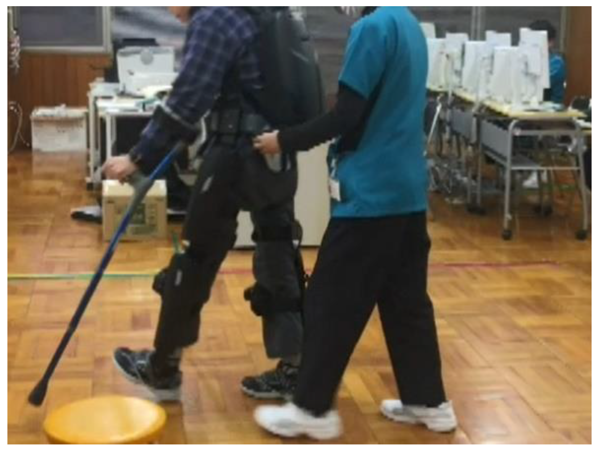
Figure 2.
Appearance of the prototype powered exoskeleton for spinal cord injury. (a) Gait trigger sensor. (b) User interface with a remote control built into Lofstrand crutches. (c) Actuators attached to the hip and knee joints. (d) Control unit and battery. (e) Separable frame. (f) Adjustment software installed on a Tablet PC.
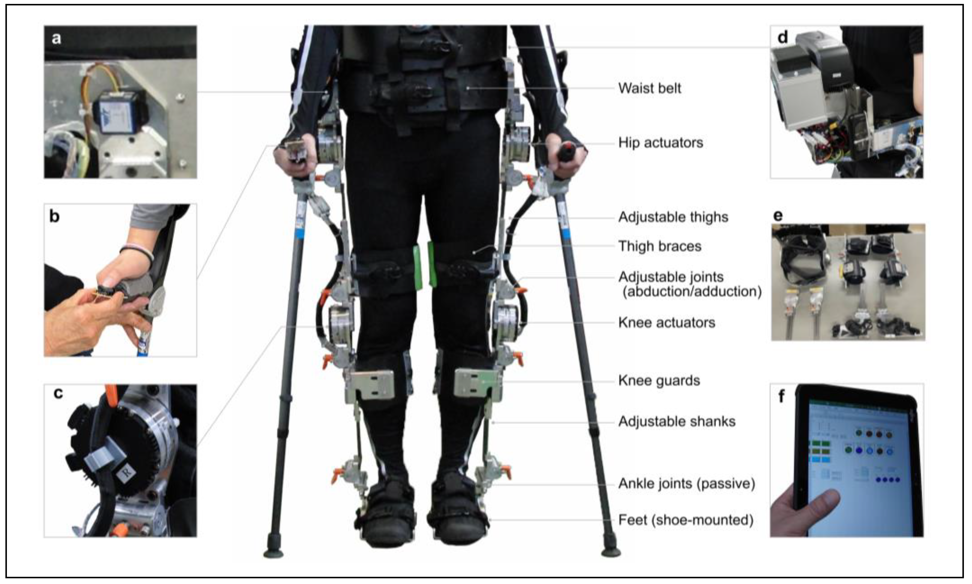
Figure 3.
Adjustable dimensions of the prototype-powered exoskeleton.
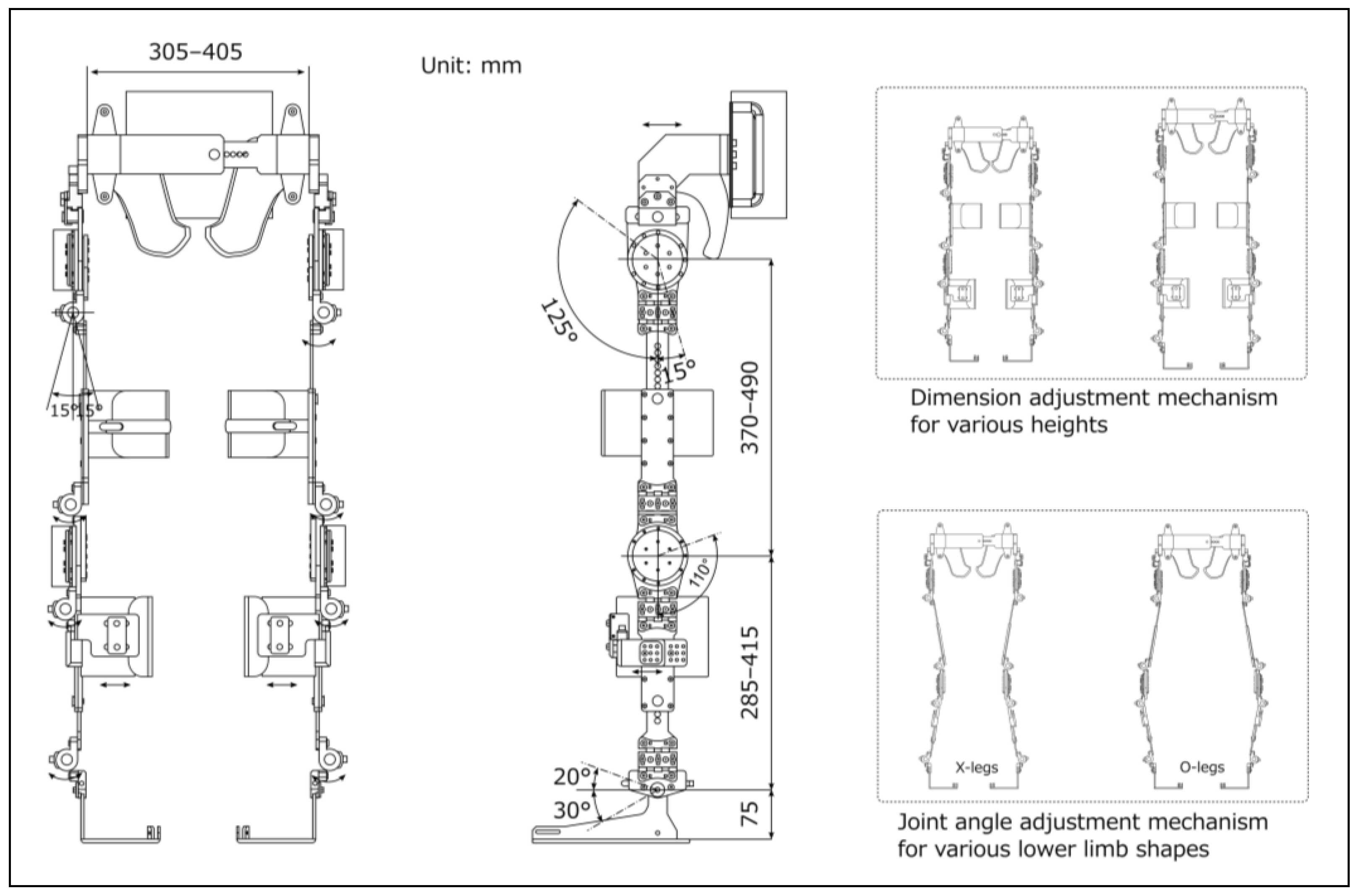
Figure 4.
Flowchart of the operating program to control the prototype-powered exoskeleton.
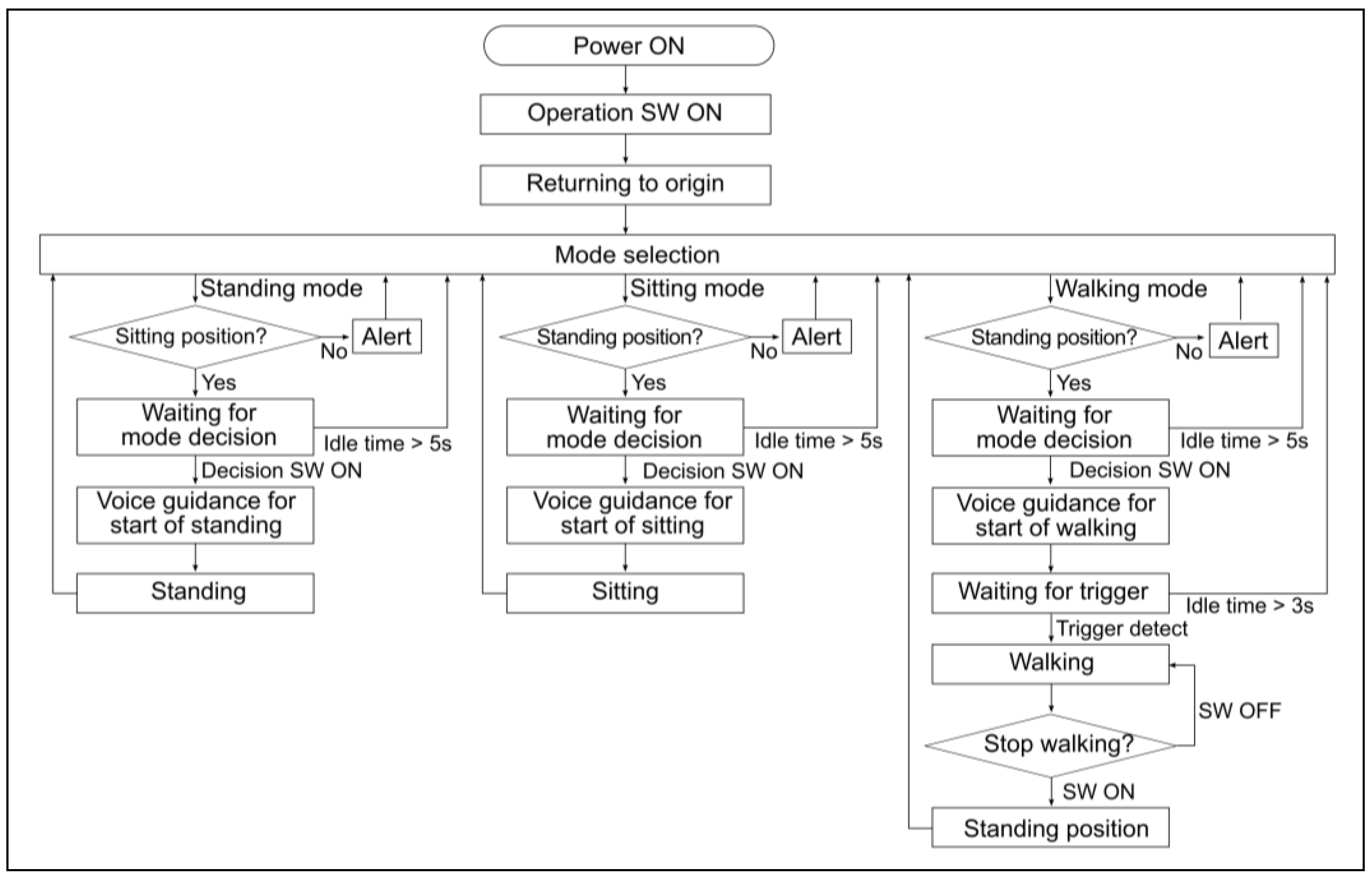
Figure 5.
Gait patterns and parameters.
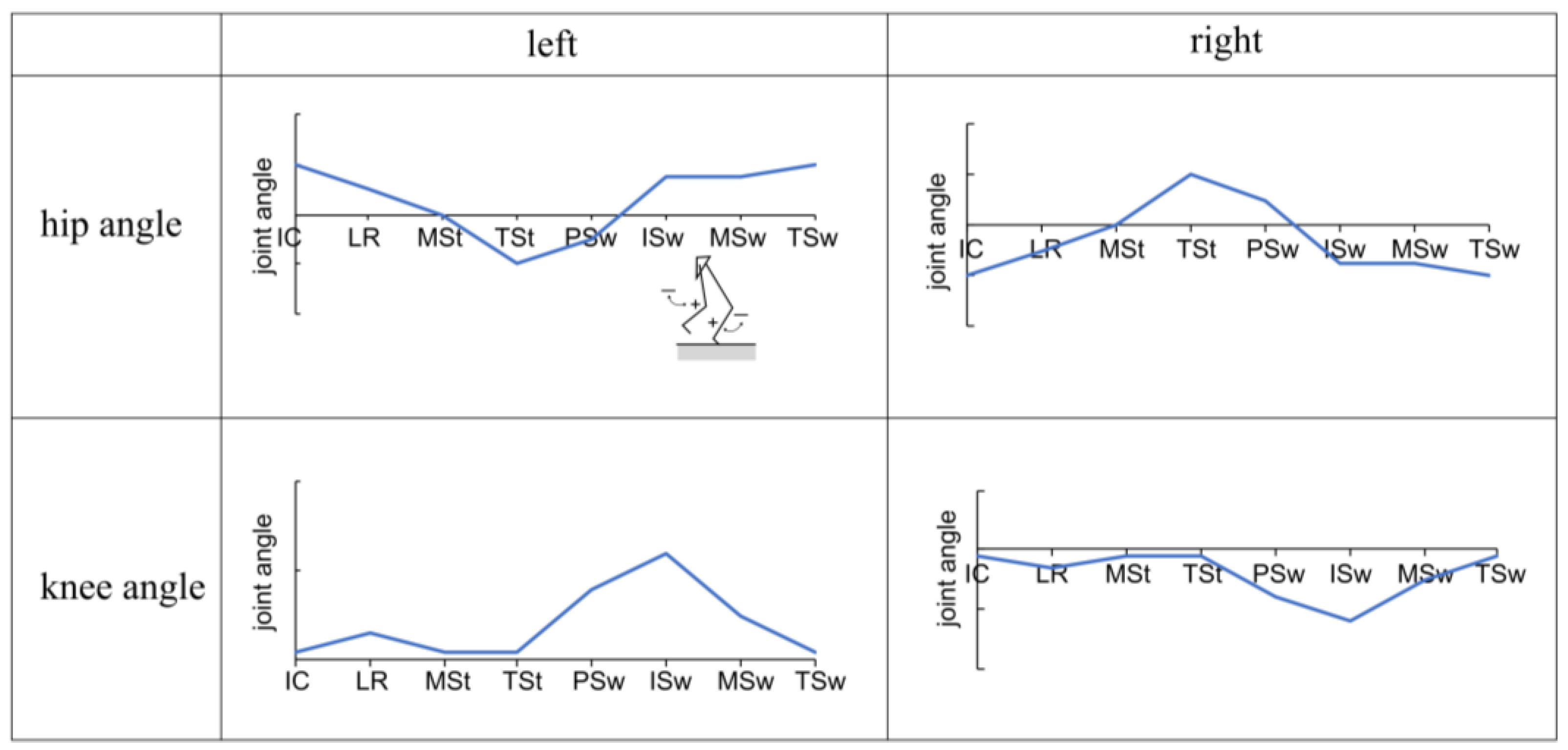
Figure 6.
Changes in hip and knee joint angles during one gait cycle with and without the prototype. The vertical axis in the figure represents joint angles, with (+) indicating flexion and (−) indicating extension. The horizontal axis is normalized to represent one gait cycle, including the swing and stance phases, at 100%. The solid line represents the subject's average, while the dashed line represents the standard deviation.
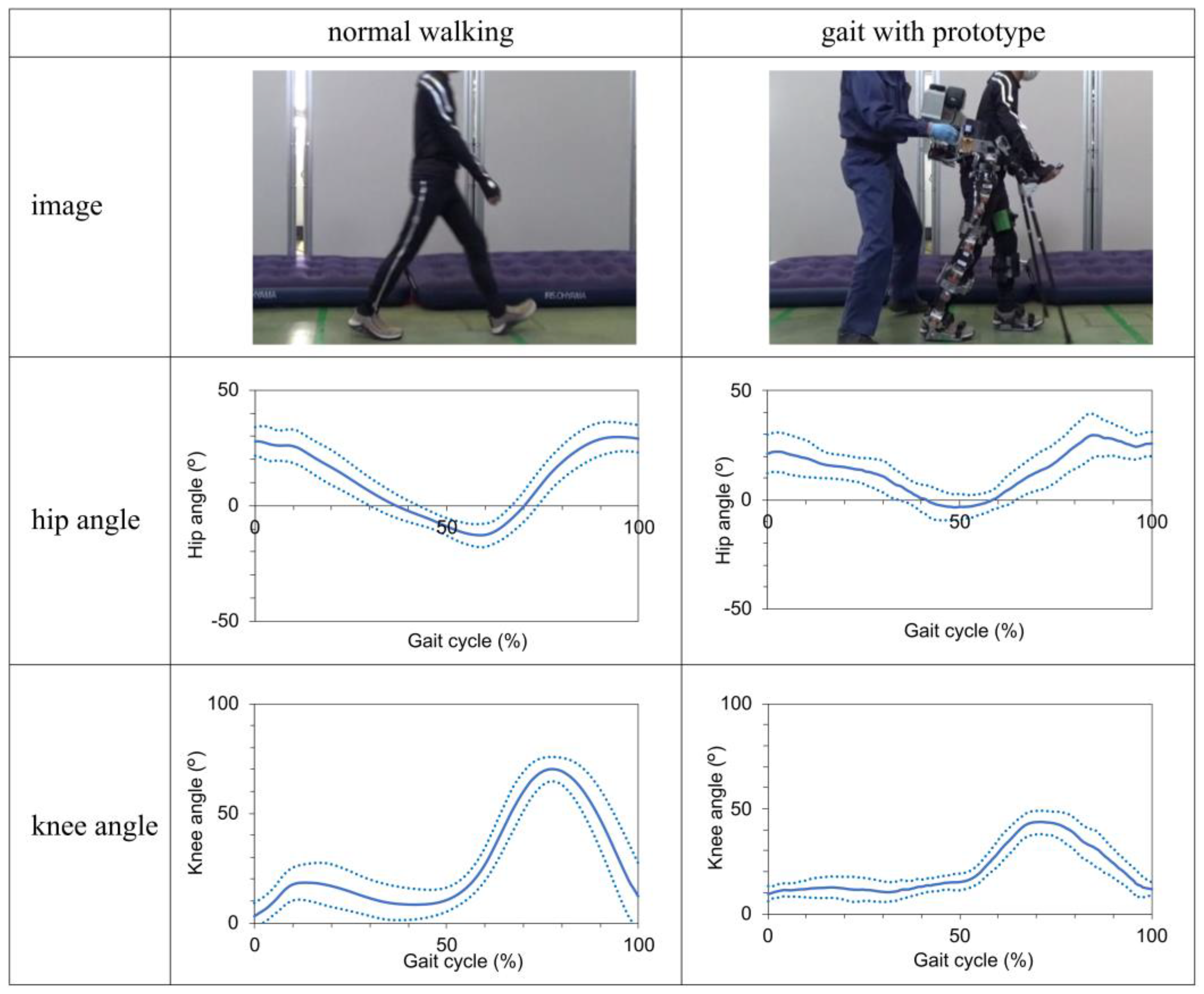
Figure 7.
Change in hip and knee joint angles during standing and sitting movements with the prototype. The vertical axis in the figure represents joint angles, with (+) indicating flexion and (−) indicating extension. The solid line represents the subject's average, while the dashed line represents the standard deviation.
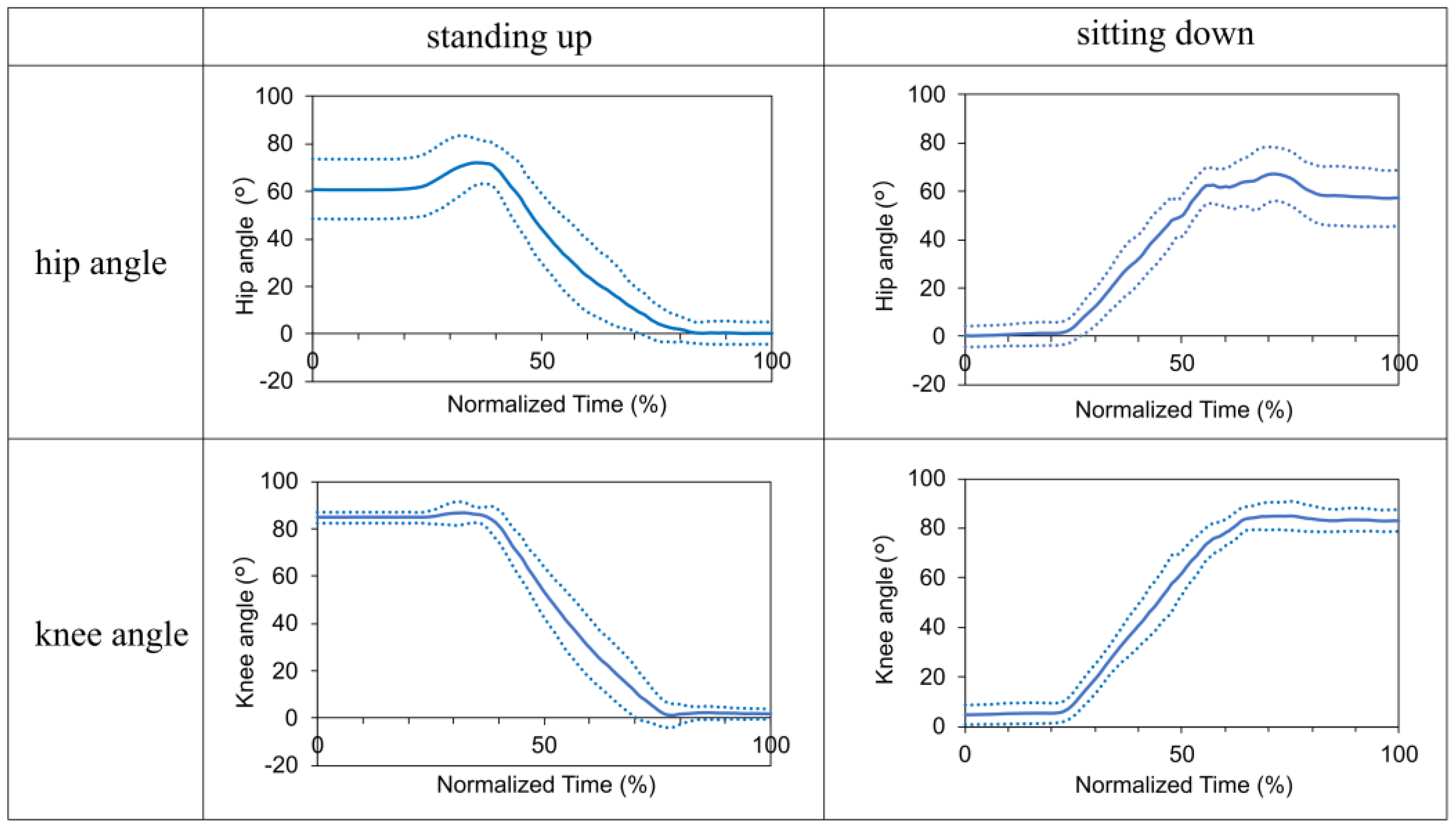

Table 1.
Key design specifications of the prototype.
| Specifications | Unit | |
|---|---|---|
| Weight | kg | 30 |
| Maximum torque | Nm | 90.9 |
| Maximum walking speed | km/h | 2 |
| Battery life | h | 1 |
| Pelvic bandwidth | mm | 305–405 |
| Thigh length | mm | 370–490 |
| Shank length | mm | 285–415 |
| Hip flexion/extension | deg | 125/15 |
| Knee flexion | deg | 110 |
| Ankle dorsiflexion/plantar flexion | deg | 20/30 |
| Hip, knee, and ankle joint adduction/abduction | deg | 15/15 |
Table 2.
Proposed design requirements for the safety and usability of powered exoskeletons for individuals with spinal cord injury.
Table 2.
Proposed design requirements for the safety and usability of powered exoskeletons for individuals with spinal cord injury.
| Elements | Outline specifications | ReWalk | Prototype | |
|---|---|---|---|---|
| Basic functions | ||||
| Exoskeleton frame including fixture | Sufficient rigidity to support weight | ✓ | ✓ | |
| Actuator | Generate the torque required for walking and sit-standing | ✓ | ✓ | |
| Gait trigger sensor | Detect body tilt | ✓ | ✓ | |
| Computers | Control and adjust the operating parameters | ✓ | ✓ | |
| Loafstrand clutch | Maintain balance and prevent falls | ✓ | ✓ | |
| Additional functions | ||||
| Dimension adjustment mechanisms | Adjustable thigh length, shank length, and pelvic band width | ✓ | ✓ | |
| Knee guards | Prevent knee bending during standing | ✓ | ✓ | |
| Krenzak mechanism | Suppress ankle plantar flexion | ✓ | ✓ | |
| Joint angle adjustment mechanism | Fit to leg shapes (X- and O-legs) | ✓ | ||
| Gel cushioning material and hip shell | Reduce pressure, prevent skin damage | ✓ | ||
| Shoe-mounted foot segment | Easy to wear while one's shoes | ✓ | ||
| Ratchet-type clasps | Easy to don/doff | ✓ | ||
| User interface built into clutch | Easy to select operation and stop mode without changing hands | ✓ | ||
| Grip for physical therapist or caregiver | Easy to provide assistance | ✓ | ||
| Split-type structure | Easy to store and transport | ✓ | ||
| Emergency stop button | Accessible to both wearer and caregiver | ✓ | ||
*The ✓ mark indicates satisfaction with the requirements.
Disclaimer/Publisher’s Note: The statements, opinions and data contained in all publications are solely those of the individual author(s) and contributor(s) and not of MDPI and/or the editor(s). MDPI and/or the editor(s) disclaim responsibility for any injury to people or property resulting from any ideas, methods, instructions or products referred to in the content. |
© 2024 by the authors. Licensee MDPI, Basel, Switzerland. This article is an open access article distributed under the terms and conditions of the Creative Commons Attribution (CC BY) license (http://creativecommons.org/licenses/by/4.0/).
Copyright: This open access article is published under a Creative Commons CC BY 4.0 license, which permit the free download, distribution, and reuse, provided that the author and preprint are cited in any reuse.
Submitted:
16 May 2024
Posted:
16 May 2024
You are already at the latest version
Alerts
This version is not peer-reviewed
Submitted:
16 May 2024
Posted:
16 May 2024
You are already at the latest version
Alerts
Abstract
Exoskeleton technology has been shown to be useful for individuals with spinal cord injury (SCI), potentially facilitating their recovery of motor function and social reintegration. However, studies on the safety and usability of exoskeletons are limited. This study aimed to design a powered exoskeleton for SCI and evaluate its safety and usability. Ten healthy adults participated in this study. The prototype exoskeleton featured an adjustable frame, computer-controlled hip and knee joint actuators, and a gait-trigger sensor. The experimental actions included walking, standing, and sitting, with and without the prototype. Safety outcomes included adverse events, vital signs, numerical rating scale (NRS) scores for pain, discomfort, and fatigue, and prototype-human body clearance. Usability outcomes included donning and doffing times, subjective ratings, gait speed, stride length, and kinematic parameters of hip and knee joint angles. Safety outcomes showed no serious adverse events, stable vital signs, minimal NRS scores, and acceptable clearance. Usability outcomes showed high efficiency and received positive ratings. Kinematic parameters showed significant positive correlations between normal walking and walking with the prototype for both hip and knee joint angles, confirming its effectiveness in assisting walking. However, further device improvements and gait parameter tuning are necessary for future clinical application.
Keywords:
Subject: Engineering - Bioengineering
1. Introduction
Spinal cord injury (SCI) is a traumatic event with a worldwide incidence ranging from 3.6 to 195.4 cases per million [1]. In 2023, approximately 18,000 new cases of SCI were reported in the United States [2], whereas in 2018, there were approximately 4,600 registered cases of SCI in Japan [3]. Occupational accidents accounted for 703 (28%) of the 2,515 cases documented in the Japanese National Spinal Cord Injury Database between 1997 and 2007 [4]. These occupational accidents are most common in the construction and civil engineering professions, usually resulting from falls. Recent trends indicate an increasing prevalence of SCI associated with falls in the aging population and tertiary industry activities [5]. Return-to-work rates of 13% [6] and 25% [7] have been reported, highlighting the need to improve treatment outcomes. It has also been reported that 70.6% of survivors of SCI are not reemployed, suggesting a compelling need for vocational rehabilitation services [8]. Although accident prevention is the primary focus of safety and health interventions, it is essential to emphasize measures that provide support for daily living and facilitate return to work after accidents.
SCI often results in paralysis, which may be complete, with the inability to recover lower limb function. Therefore, assistive devices, such as orthoses and wheelchairs, may become necessary for mobility. Exoskeleton technology has recently emerged as a promising solution for gait rehabilitation and mobility in patients with SCI. According to the U.S. Food and Drug Administration (FDA), a powered exoskeleton is a prescription device consisting of an external motorized orthosis placed over paralyzed or weakened lower extremities for rehabilitative purposes [9]. These devices can potentially restore locomotive function, allowing individuals with SCI to gradually reintegrate into their homes, communities, and workplaces. The use of powered exoskeletons in rehabilitation dates back to the early 1970s [10]. Advancements in digital technology have enabled the implementation of various exoskeleton models. Reports have shown promising results, especially with commercial exoskeletons such as ReWalk, Indego, and Ekso, which have undergone rigorous FDA certification testing and have helped patients with paraplegia regain walking independence [11,12,13]. Systematic [14,15] and scoping [16] reviews have further supported their clinical effectiveness. In addition, exoskeletons can potentially increase activities of daily living, both at home and in the community [17].
However, challenges exist with the use of exoskeletons, including device malfunctions, skin injuries, device misalignment, user errors, and falls [18]. Commercial exoskeletons use various strategies to reduce these challenges. For instance, they continuously supervise users in order to reduce the risk of falls. Figure 1 shows a scenario of gait rehabilitation using an exoskeleton in a clinical setting. Through hands-on assistance and monitoring, physical therapists play a crucial role in preventing patient falls using exoskeletons [19]. Further, the safety of physical therapists must be ensured as they are also at risk of falls.
Although human assistance is necessary to ensure safety, no established safety guidelines exist for exoskeleton use. These devices present technical challenges, including substantial weight, limited joint mobility, motor noise, and high cost. Overcoming these challenges requires improved technology and extensive research.
The evaluation of exoskeletons also presents several challenges. Most clinical trials focus on outcome measures such as ambulation, balance, physiological improvements, energy consumption, ease of use, and comfort [20]. However, research on the safety of exoskeletons [21] and quantitative evaluations, such as gait analysis of individuals using exoskeletons, are limited. Moreover, the accuracy of measurements may be limited by the challenges associated with conventional measurement methods. Due to the exoskeleton frame, optical motion capture systems may obscure the markers, whereas mechanical joint goniometers may experience interference from the exoskeleton.
Therefore, this study aimed to investigate the safety, usability, and kinematic performance of an exoskeleton designed for individuals with SCI. This study provides an overview of the prototype exoskeleton and presents the results of an experimental study involving healthy participants. It also proposes standard specifications to enhance the safety and usability of exoskeletons. This research provides a foundation for future clinical applications.
2. Materials and Methods
2.1. Prototyping
2.1.1. Overview of Prototype Exoskeleton
Figure 2 shows the external features of the prototype exoskeleton, and Table 1 highlights its key specifications. The primary unit consists of a structure resembling a hip-knee-ankle-foot orthosis equipped with a gait trigger sensor, a control unit, a battery, and actuators. Additionally, it includes forearm-supported clutches (Lofstrand crutches) with an operational interface and a tablet PC equipped with adjustment software.
The exoskeleton design concept prioritizes safety and user-friendliness. Its main objective is to restore the mobility of individuals with SCI to a level comparable to that of their healthy counterparts. The design was inspired by the lower-limb-powered orthosis developed by Miyamoto et al. [22], and it aligns with the FDA's definition of a medical exoskeleton [9].
We adhered to a structured schedule to implement this design concept, achieving milestones in between. In 2020, we conducted a comprehensive survey and performed a risk assessment of existing exoskeletons [19]. In 2021, we focused on engineering principles and user assistance. We developed a design concept, established requirements for the design, and created it. In 2022, we integrated an actuator and a control system into the exoskeleton structure, resulting in a functional prototype [23]. In 2023, we tested the prototype exoskeleton [24].
Our fundamental design requirements were set using the ReWalk exoskeleton (ReWalk Robotics, Inc., Yokneam, Israel) as a reference, focusing on safety and usability. Our initial criteria included height adjustments, accommodation of variations in leg alignment, ease of use, portability, overload protection, and a user-friendly interface. Input and feedback were gathered from medical doctors and physical therapists and incorporated into the design specifications.
The target users of this product are individuals with SCI at levels T4–L5 in hospitals and rehabilitation centers. These individuals experience complete paralysis of their lower extremities but have good upper limb functionality and balance. They should have a height of 145–180 cm and a weight limit of 80 kg. The exoskeleton assists individuals in walking, maintaining posture, and transitioning between sitting and standing using Lofstrand crutches. There are two classifications of exoskeleton types. One is treadmill-based, and the other is orthosis-based (overground exoskeleton), which our study focuses on. Preventing falls is a top priority. However, there are potential challenges with developing fall prevention technologies based on current capabilities, such as a predictive fall detection and control technology. A trunk-mounted harness can also reduce falls; however, practical limitations in clinical settings have led to its exclusion. Hence, this study assumed that the prevention of falls depends on traditional human support, such as contact assistance and monitoring by physical therapists.
2.1.2. Design Elements
2.1.2.1. Structure
Figure 3 shows the structural dimensions and functions of the prototype. The prototype was ergonomically designed with adjustable components and braces. These incorporated soft-padding materials to minimize the risk of skin injuries and misalignment. The structural dimensions were customized to accommodate a wide variety of individuals, ranging from the 5th percentile for adult females to the 95th percentile for adult males, based on Japanese anthropometric data [25]. This customization included a pelvic bandwidth ranging from 305 to 405 mm, thigh segment ranging from 370 to 490 mm, and shank segment ranging from 285 to 415 mm. Each segment included a sliding mechanism that could be easily secured with pin-type screws, thus simplifying the adjustments without the need for additional tools.
The joint range of motion was set according to the guidelines of the Japanese Orthopaedic Association, the Japanese Society of Rehabilitation Medicine, and the Japanese Society for Surgery of the Foot [26]. The hip joint had a range of 140°, with flexion of up to 125°, and extension of 15°. The knee joint had a range of 110° with flexion up to 110° and extension of 0°. The ankle joint had a range of 50°, with a dorsiflexion of 20° and plantar flexion of 30°. This configuration ensured the necessary ranges of motion for standing and walking. This prototype permits angle adjustments within a range of 15° in the directions of adduction and abduction of the hip, knee, and ankle joints. This feature accommodates variations in lower-limb shapes, such as the X-leg or O-leg. The design was inspired by Kardofaki's scalable exoskeleton [27]. The ankle joints include a passive mechanism inspired by the double Klenzak design to effectively limit dorsiflexion during walking. This mechanism is particularly beneficial for patients with paraplegia.
The prototype also included foldable and detachable knee guards to prevent knee flexion while standing. A gel-like material (EXGEL; Kaji Corp., Shimane, Japan) was used for the inner surfaces. The thigh braces had a large contact surface area and were equipped with a soft, 10-mm-thick urethane padding. Additionally, a three-dimensional molded resin component, called the “hip shell,” was attached to the pelvic band to conform to the contours of the pelvis. This lowered the pressure on the sacral area, reducing its susceptibility to pressure ulcers.
The foot components were designed to be shoe-mounted, allowing users to wear them over their existing footwear. Attachment to the body was done using strap belts on the waist, thighs, shanks, and feet. These belts featured ratchet-type buckles for added convenience, unlike traditional velcro closures. Additionally, a detachable handle was strategically positioned on the rear side of the pelvic band to assist physical therapists in providing support. The structural frame was primarily composed of duralumin and weighed 12.8 kg. It could be dismantled into the pelvic, thigh, shank, and foot components for easy transport and storage.
2.1.2.2. Actuator
During typical walking, the hip joint requires a maximum normalized torque of approximately 1.1 Nm/kg [28], whereas rising with arm support requires roughly 0.72 Nm/kg at the knee joint [29]. When walking with crutches, approximately 47% of the body weight is supported [30]. We assumed a maximum patient weight of 80 kg (95th percentile adult males in Japan) and an exoskeleton weight of 30 kg. Using this information, we estimated that the hip joint torque required for walking with crutches is approximately 64 Nm and the knee joint torque required for standing movements with crutches is approximately 79 Nm. Therefore, the motor torque required for the exoskeleton exceeded 79 Nm.
To satisfy this requirement, an ultra-flat actuator (model number: WPMZ-50-100-SN-3958; NIDEC Corp., Kyoto, Japan) was selected and integrated into the hip and knee joints of the frame. These actuators had a reduction gear with a 1:101 ratio. They were equipped with a brushless DC motor (rated voltage: DC48V, rated capacity: 220 W, rated rotation speed: 29.7 rpm) capable of producing a rated torque of 47 Nm and a maximum torque of 90.9 Nm. Each actuator weighed 1.1 kg, with an outer diameter of 90 mm and a thickness of 50.5 mm. This made them the slimmest and lightest actuators in their category. Despite a high reduction ratio of 1:100, they maintained excellent backdrivability (approximately 11 Nm), allowing for a manual axis drive after disengagement of the servo.
The actuator was equipped with safety features, including an integrated encoder and a dedicated motor driver (model number: FWPB4338120-48; NIDEC Corp., Kyoto, Japan) that continuously monitors and regulates the position, speed, and torque. These protective mechanisms are designed to address potential anomalies such as overcurrent, overload, and excessive speed. They also help to automatically halt the actuator whenever an overload is detected. In addition, the actuator includes software limiters and mechanical stoppers as hierarchical safety mechanisms to prevent unintended movements.
If the emergency stoppage, including automatic stoppage, is activated while walking, the hip and knee joints are locked in their respective positions, and the servos remain engaged. The servos could be deactivated by releasing the emergency stop button, allowing the exoskeleton to return to a standing position under its weight while receiving the frictional force due to backdrivability. However, it is essential to emphasize that the assistance of therapists is necessary in such situations.
2.1.2.3. Gait Trigger Sensor
A motion sensor (BWT61 Gyroscope sensor; WitMotion Co., Ltd., Shenzhen, China) for gait triggering was attached to the side of the pelvic band to account for the possibility of neuroplasticity with voluntary movement among the patients. The walking mode is activated when the user tilts their trunk forward and surpasses a predefined angle, initiating the walking sequence.
2.1.2.4. Control Unit
The control system utilizes a programmable logic controller (PLC) (KV-8000; KEYENCE Corp., Osaka, Japan) to manage functions, such as standing, walking, or sitting modes, gait triggers, walking cessation, voice-guided instructions, and abnormalities with handling. The aluminum housing on the back of the pelvic band enclosed the PLC and related components, including motor drivers and a DC48V lithium-ion battery (eBike Battery; Guangdong Greenway Technology Co., Ltd., Dongguan, China), with a combined weight of approximately 16 kg.
Figure 4 shows a flowchart of the operational program, which follows these steps: (1) The user attaches the exoskeleton while in a servo-stopped state at the origin. (2) To initiate standing movement, standing mode is selected and confirmed. (3) After a successful standing movement, each axis actuator maintains its standing position in the servo-stopped state. (4) To start walking, the user should select walking mode and then wait for the walking-start trigger. Walking is automatically initiated when the motion sensors detect a forward inclination beyond a preset angle. Pressing the walking-stop switch causes the swinging leg to return to a standing position via the shortest route in the servo-stopped state. If the sitting mode is selected, the system returns to the servo-stopped state upon completion of the sitting movement from the standing position.
Gait patterns were created using dedicated PLC software (KV COM+ for Excel, Ver. 1.4; KEYENCE Corp., Osaka, Japan). The basic gait pattern was set based on the eight gait phases set by the Rancho Los Amigos Hospital [31], with the knee and hip joint angles serving as references for typical gait in a healthy individual. In addition to joint angles, velocity, acceleration, and deceleration were considered for each gait phase. Gait was achieved by sequentially connecting the parameters.
Figure 5 shows the variations in hip and knee joint angles during the gait cycle. The vertical axis represents these joint angles, and adjustments to the flexion or extension angles can be made by modifying these values. Meanwhile, the horizontal axis represents the timeline, and the timing of flexion or extension is adjustable through modifications to velocity, acceleration, and deceleration.
The PLC memory stores a predefined basic gait pattern, allowing the autonomous operation of the exoskeleton. The predefined gait parameters were assumed to be adjusted based on the patient's condition. A user-friendly graphical interface software was developed to facilitate this process. The program can be installed on a tablet or laptop with a Windows OS. Physical therapists are thus able to use this feature to adjust the gait parameters to meet the specific clinical needs of their patients.
2.1.2.5. User Interface
This design differs from the ReWalk reference model because it allows patients to control the exoskeleton independently, eliminating the need for specialized training. This was achieved by converting a commercially available clutch grip into a versatile switch that users can operate directly. Intentional designs were incorporated to minimize the risk of user error. As highlighted in a previous study [32], the mode-selection switch was on the right grip, whereas the stop switch was on the left.
To enhance safety, an algorithm-based timed-timer function was incorporated to automatically reset the system to its initial state after a specified elapsed time period from activation of the mode-selection switch. Furthermore, the idle time was set to a minimum of 5 s, as shown in Figure 4. This feature guarantees that patients can revert to their original state even if the switch is accidentally or incorrectly activated.
In addition, the device was equipped with MP3 playback alarms and Bluetooth technology connected to the PLC, allowing for synchronized voice-guided instructions that correspond to the operational mode. When an immediate halt in operation is necessary, emergency stop can be easily accessed through switches on both the clutch grip (by long-pressing the stop button) and control unit. This enables users to initiate emergency cessation in response to anomalies or psychological distress. Exiting the emergency stop mode deactivates the servo, allowing manual adjustments of the joint angle through the therapist's assistance without significant resistance from the motor.
2.2. Experiment
This experiment aimed to evaluate the efficacy of the prototype while performing movements such as walking, standing up, and sitting down.
2.2.1. Participants
Ten healthy adults (seven males and three females) participated in this study and provided written informed consent.
2.2.2. Instruments
The experimental device used in this setup was a prototype exoskeleton. Prior to the experiment, the participants were made to familiarize themselves with the device using a custom-made walker equipped with casters. The walker was made of an aluminum frame with specific dimensions: a width of 120 cm, depth of 120 cm, and height of 212 cm.
The study employed several measuring instruments, including the Martin Anthropometer (Tsutsumi Work Inc., Chiba, Japan) for measuring human body dimensions, a caliper for measuring clearance between the human body and the exoskeleton, a Smartwatch-H2 (itDEAL; China) for heart rate monitoring, and an upper arm sphygmomanometer (Model HEM-7600T; OMRON Corp., Kyoto, Japan) for systolic and diastolic blood pressure measurements. The donning and doffing times of the exoskeleton and the walking time were recorded using a stopwatch. The experiment was performed using two digital video cameras (Model HDR-CX680; SONY Corp., Tokyo, Japan). A numerical rating scale (NRS) questionnaire was used for subjective assessments.
This study used a markerless motion capture system (e-skin MEVA; Xenoma Inc. Tokyo, Japan) to measure hip and knee joint angles. Measuring kinematic parameters with conventional methods when using exoskeletons presents challenges owing to the hiding of the marker by the exoskeleton frame in optical motion capture systems. Additionally, mechanical joint goniometers may encounter interference issues from the exoskeleton frame, which could compromise measurement accuracy. Consequently, the sensors are either integrated into the exoskeleton rotor or attached externally to the exoskeleton [33,34]. However, these approaches primarily track the movements of the exoskeleton and do not directly capture the individual motions of the wearer.
In contrast, the e-skin system has a bodysuit-type design that can be worn like clothing, ensuring minimal interference with the exoskeleton frame. The system uses an inertial measurement unit (IMU) sensor that comprises 3-axis acceleration and gyro sensors to calculate motion based on sensor data. The algorithm developed by Teufl et al. [35] enables motion calculation solely based on accelerometers and gyro sensors without relying on geomagnetism. Consequently, the system is unaffected by geomagnetic interference, which is a drawback of the IMU. This ensured stable measurements even in the presence of a motor in the exoskeleton.
The IMU sensors were positioned at 18 locations: one on the headband, ten on the upper-body shirt, and seven on the lower-body pants. The sensors were remarkably slim, measuring 20 mm in width, 35 mm in height, and 2 mm in thickness. The accelerometer had a range of ±30 G and a resolution of 16 bits, while the gyro sensor had a range of ±4000 dps and a resolution of 16 bits. Compared with optical methods, this method produces joint angle differences of only 2° with a correlation coefficient of 0.98 for the hip and knee joint angles in the sagittal plane [35]. Data were recorded at a sampling frequency of 100 Hz and transferred to a PC via Bluetooth.
2.2.3. Procedure
As part of the experimental preparation, the participants were given detailed instructions on how to operate the prototype. Vital signs were recorded, and a Martin anthropometer was used to measure their thigh lengths, lower leg lengths, and waist widths. The length and width of the exoskeleton frame were adjusted based on the respective measurements. Finally, participants donned the prototype while seated. During this process, the participants performed a standing motion to evaluate the tightness of the straps or belts with the necessary adjustments. Simultaneously, the joint angles of the left and right lower limbs were adjusted, and clearance measurements were performed. After completing this stage, the participants returned to their seats, and the prototype was removed.
The participants wore calibrated markerless motion-capture suits, and each completed two 6-meter walks at their usual pace. Joint angles were recorded using motion-capture technology, walking time was measured with a stopwatch, and frontal and side views were captured using video cameras.
The participants then donned the prototype again while seated. The time taken to don the prototype while seated was recorded using a stopwatch. The participants were trained on the use of the prototype with a specialized walker, and they practiced using crutches. The participants were allowed to choose between simultaneous bilateral or alternating thrusting motions with crutches. They were instructed not to exert force on their lower limbs while walking, sitting, or standing with the prototype. A caregiver stood behind each participant to ensure safety and prevent falls. Furthermore, air mats were placed on both sides of the walking path. Participants completed a 6-meter walk with the prototype twice. Joint angles were recorded using motion capture technology, walking time was measured with a stopwatch, and frontal and side views were captured with video cameras.
The participants also performed two sitting and standing movements using the prototype. The joint angles were continuously monitored during the movements, and side-perspective video recordings were performed. After the activities, the prototype was removed, and the time taken for doffing was measured using a stopwatch.
Finally, the participants completed the NRS questionnaires, and their vital signs were recorded. Interviews were conducted to gather comprehensive feedback. The experimental procedure lasted approximately 1.5–2 h.
2.2.4. Outcome Measures
2.2.4.1. Safety
The main objective of the safety evaluation was to assess the impact of the prototype on the participants while ensuring that there were no unexpected risks or side effects. Safety outcomes included the assessment of serious adverse events (SAEs) and adverse events (AEs) associated with device usage. The SAEs and AEs were evaluated according to the guidelines provided by ISO 14155:2011, MEDDEV 2.7/3, and MDCG 2020-10/1.
Potential adverse events were assessed by measuring the heart rate in beats per minute (bpm), systolic and diastolic blood pressures in mmHg, and oxygen saturation (SpO2) in % before and after each session. Pain and discomfort levels were evaluated using an 11-point NRS, where 0 indicated no pain or discomfort, and 10 indicated very intense pain or discomfort. Falls and physical injuries resulting from use of the device were also recorded.
The clearances between the human thigh and lower limb and the thigh and shank segments of the prototype were also measured in millimeters using calipers. This measurement evaluated compliance with the checkout criteria for lower limb orthotics, where clearance was set at approximately 5–7 mm for nonarticulated regions [36]. A narrow clearance means an increased risk of skin injuries, whereas an excessively wide clearance may lead to increased friction with clothing.
2.2.4.2. Usability
The main objective of the usability test was to evaluate the ability of the participants to operate the prototype correctly. Usability was assessed by measuring the time used by the participants in wearing and removing the device. Donning time referred to the time required to attach the strap belts to the pelvic area, thighs, shanks, and feet while the participant was in a seated position. Conversely, the doffing time was used to describe the duration required to remove the strap belts from these same locations. Additionally, a questionnaire was administered to assess the ease of donning and doffing as well as the subjective sensation of fit at three specific sites: the pelvic area, thighs, and shanks. The rating scale consisted of 11 points, aligned with the previously described NRS, ranging from 0 (difficult to don/doff) to 10 (very easy to don/doff) and from 0 (not fit) to 10 (very fit).
Gait velocity (measured in meters per second) was calculated using the walking distance and time. The stride length (measured in meters) was calculated using the walking distance and number of steps taken during walking with and without the prototype.
2.2.4.3. Kinematic Parameters
The main objective of the kinematic analysis was to verify whether the prototype functions as intended for the walking, standing, and sitting movements. The outcomes were measured using markerless motion capture. The measurement focused on the hip and knee joint angles (measured in degrees) during gait with and without the prototype, as well as during sitting and standing with the prototype.
Data from the second trial were used for gait analysis. To account for the variability in walking time among the individual participants, the joint angle data within a single gait cycle were normalized, including both the swing and stance phases, and defined as 100%. We then used the maximum (peak flexion angle) and minimum (peak extension angle) hip and knee joint angles to represent and compare the differences attributed to the exoskeleton usage.
The gait cycle was divided into eight phases, each with a specific percentage of the cycle according to the Rancho Los Amigos Hospital method: initial contact (IC) at 0%, loading response (LR) at 0–12%, mid-stance (MSt) at 12–31%, terminal stance (TSt) at 31–50%, pre-swing (PSw) at 50–62%, initial swing (ISw) at 62–75%, mid-swing (MSw) at 75–87%, and terminal swing (TSw) at 87–100% [31]. At each of these phases, stable hip and knee joint angles were extracted. The correlations between normal gait and gait with the prototype were then analyzed for these datasets.
Data from the second trial were used to analyze the standing-up motion. The analysis was divided into three segments: the initial 2 s in the seated position, the middle 3 s in the standing-up trial, and the final 2 s in the standing position. All segments were normalized to 100% for accurate representation. The analysis of the sitting-down motion followed an approach similar to that of the standing-up motion.
2.2.5. Statistical Analysis
The data are presented as mean ± standard deviation. Paired t-tests were used to compare mean vital data before and after the session. It was also used to compare gait velocity, stride length, and peak flexion/extension angles of the hip and knee joints with and without the prototype. In addition, Pearson's correlation coefficients were calculated for the hip and knee joints during a single gait cycle with and without the prototype. All statistical analyses were conducted using IBM SPSS Statistics version 28 (IBM Corp., Armonk, N.Y., USA). Statistical significance was set at p < 0.05.
3. Results
3.1. Analyzed Participants
The ten participants had the following characteristics: mean height 167 ± 10 cm (range: 152–179 cm), mean weight 58 ± 9 kg (range: 41–70 kg), and mean body mass index 21 ± 2 (range: 17–25).
3.2. Safety Outcomes
No SAEs or AEs were observed. However, a minor problem occurred while walking with the prototype; a participant lost balance and fell nearly diagonally forward to the left. Notably, the caregiver promptly intervened to prevent injury. At this point, the caregiver stopped the prototype by pressing the emergency stop switch on its back. Hence, we confirmed that an emergency arrest was performed without complications.
The mean heart rate was 74.3 ± 12.1 bpm before the session and 79.6 ± 12.5 bpm after the session. Mean systolic blood pressure was 125.0 ± 19.7 mmHg before the session and 119.8 ± 9.8 mmHg after the session, while mean diastolic blood pressure was 76.6 ± 11.8 mmHg before the session and 73.6 ± 3.0 mmHg after the session. Mean SpO2 was 97.4 ± 0.7% before the session and 97.7 ± 0.9% after the session. No significant differences were observed between the pre- and post-session measurements for any of the parameters.
The mean pain and discomfort ratings were recorded using the NRS scale as follows, respectively: pelvis area= 0.0 ± 0.0, 0.2 ± 0.7; thigh area= 0.1 ± 0.3, 0.3 ± 0.7; and lower leg area= 0.7 ± 1.1, 0.4 ± 0.7. No pain or discomfort ratings exceeded 3 during the sessions. The fatigue rating was 1.1 ± 0.8. None of the participants reported experiencing fatigue severe sufficient to make them stop the session.
The mean distance between the device and the human body was 10.2 ± 4.6 mm for the thigh and 10.9 ± 5.2 mm for the shank.
3.3. Usability Outcomes
The average time required for donning the device was 3.8 ± 0.6 min, while the mean doffing time was 0.6 ± 0.2 min. The ease of donning or doffing was reported as follows: around the pelvis= 4.8 ± 2.3; in the thigh region= 5.1 ± 2.1; and in the lower leg region= 4.7 ± 2.4.
The ratings for the feeling of fit were as follows: around the pelvis = 6.2 ± 3.0, in the thigh region = 7.0 ± 3.0, and in the lower leg region = 7.1 ± 3.0.
Participants achieved a mean gait velocity of 1.0 ± 0.1 m/s during normal walking, which decreased to 0.1 ± 0.1 m/s when using the prototype. Similarly, stride lengths were 1.2 ± 0.1 m during normal walking but decreased to 0.8 ± 0.3 m when using the prototype. Statistical analysis revealed significant differences in gait velocity (p < 0.001) and stride length (p = 0.0025) with and without the prototype.
3.4. Kinematic Analysis Outcomes
The results of the kinematic parameters of the hip and knee joints throughout the gait cycle are shown in Figure 6. Significant positive correlations were observed between normal walking and gait with prototype in both the hip joint angle (r = 0.70, p < 0.001) and the knee joint angle (r = 0.84, p < 0.001). The mean peak flexion angles of the hip joint were 30 ± 3.5° for normal walking and 30 ± 6.1° when using the prototype. The mean peak extension angles of the hip joint were -13 ± 3.7° for normal walking and -6 ± 5.1° when using the prototype. Significant differences in these parameters were observed between the two scenarios (p = 0.002). The peak flexion angles of the knee joint were 74 ± 4.5° with normal walking and 44 ± 5.2° when using the prototype, with significant differences observed between the two scenarios (p < 0.001).
Figure 7 highlights the angular changes observed in the hip and knee joints during the sit-to-standing process. The hip joint was flexed immediately before initiating the standing movement and transitioning to an extended position. Simultaneously, the knee joint shifted from a flexed to an extended posture as the participants assumed a standing position. As the participants descended from standing to sitting, the hip joint transitioned from extended to flexed, with a similar shift observed in the knee joint.
4. Discussion
This paper presents a prototype exoskeleton designed for individuals with SCI. Experiments were conducted to evaluate the safety and usability of the materials.
4.1. Safety and Usability
Although no SAEs or AEs were observed, one of the participants lost balance, but quick action was taken by the caregiver to prevent injury. This incident was related to the experimental procedure and not the device itself. However, the joint movement of the prototype is limited to one axis of flexion-extension. This feature should be particularly useful for the initial training of patients with lower limb paralysis; however, it may have been difficult for a healthy participant whose hip joints move in three dimensions during walking. Furthermore, a slower setting with abnormal walking patterns may have contributed to this event. Furthermore, human factors, such as learning forward while using crutches and inadequate training, may have played a role. These findings highlight the need for additional device enhancements and user training to ensure participant safety.
No significant differences were observed in the vital signs before and after the experiment. The subjective pain, discomfort, and fatigue ratings were minimal, with no session interruption. Therefore, it can be inferred that the health risks associated with exoskeleton use are low. The mean clearance between the thigh and lower leg was 10 mm. Compared with the criteria for lower-limb orthotics, the clearance values of the prototype are slightly larger but still within a reasonable range. The subjective fit ratings consistently indicated high levels of comfort in all areas. The ergonomic approach of combining adjustable structures and soft materials within a brace effectively minimizes skin problems and misalignment, as evidenced by the low pain and discomfort ratings. These results could also benefit physical therapists via the potential of eliminating traditional tasks, such as applying and removing pads, thereby streamlining the preparation process in clinical settings.
The time required to don and doff the device was reasonable, and subjective ratings of the ease of donning and doffing suggested the process was relatively straightforward. Conversely, according to a previous study, it took approximately 7 min to don and 2 min to doff the conventional device (ReWalk) [19]. It is important to note that these time durations include the time used in applying and removing the pads to prevent skin abrasions; therefore, it is difficult to make direct comparisons. However, our prototype successfully had lower donning and doffing times. This improvement was due to the switch from the traditional velcro system to the ratchet system, allowing for easy adjustment, secure attachment, and quick, one-touch removal.
4.2. Kinematic Parameters
We found that the prototype successfully executed the intended walking, standing, and sitting programs. The kinematic results during walking indicate nearly identical hip and knee joint patterns with and without the prototype, proving that the prototype provides gait assistance.
However, significant differences were observed in the peak values of the knee joint flexion angle and hip joint extension angle. During the stance phase of walking with the prototype, the knee was inadequately flexed, particularly during the weight response phase. In addition, the maximum angle of knee flexion during the swing phase was smaller than that during normal walking. Furthermore, the maximum hip extension angle with the prototype was smaller than that during normal walking. On observation, it appears like the foot makes ground contact before the knee fully extends and that there is a forward-leaning posture owing to the use of crutches. These factors may be related to the shorter stride length of the prototype compared to normal walking. Therefore, adjusting the settings of the prototype's walking program will be necessary in the future.
In addition, the mean gait velocity achieved with the prototype was only 10% of that in normal walking. This was because the participants were using the exoskeleton for the first time, and some expressed apprehension about going faster. Hence, the speed of the exoskeleton was intentionally set to a slow pace to improve safety. According to the opinion of a physical therapist with experience in using exoskeletons, the speed is usually initially set to slower, although faster speeds make walking more stable. As the prototype's specifications allow it to reach speeds of up to 0.5 m/s, equivalent to that of a conventional exoskeleton, it will be necessary to gradually adjust the speed according to the user's condition and proficiency level.
4.3. Proposed Design Specifications for Safety and Usability
As shown in Table 2, based on the results of the evaluation experiments, we can propose design specifications for an exoskeleton for individuals with SCI, considering safety and usability. The table also includes a comparison with conventional ReWalk products. The prototype incorporates unique features such as joint angle adjustment mechanisms, gel-type cushioning material, hip shells, and modularity, while still maintaining basic functionality equivalent to that of conventional products, including the ability to assist with walking, standing, and sitting. These additions were designed to enhance safety and usability.
4.4. Study Strengths and Limitations
A major strength of this study is that we developed a novel exoskeleton for individuals with SCI and quantitatively measured subtle body movements within the exoskeleton frame using a markerless motion capture system, which was previously considered difficult. Our results provide strong evidence that the prototype can successfully perform walking, standing, and sitting movements when worn by healthy participants. This performance suggests that the prototype has properties similar to conventional exoskeletons and can potentially improve the walking ability of individuals with SCI. In addition, the prototype exoskeleton effectively addressed common problems associated with the use of exoskeletons, including skin injuries and misalignment. Key features, such as adjustable dimensions and joint angles, cushioning materials, ratcheting fasteners, and a wireless operating interface built in to the clutch, improve the safety and usability of the exoskeleton.
However, this study has some limitations which must be acknowledged. We used a small sample size and relatively short experimental duration, which could have introduced some bias into our findings. This could be addressed by expanding the study to include more participants and longer-term investigations. In addition, there were technical challenges, particularly with the weight of the prototype, which exceeds that of conventional devices. Lightweight materials such as carbon fibers, battery capacity adjustments, and a specially designed control system instead of a general-purpose PLC could be explored to achieve the desired weight target. Adjusting gait parameters based on normal gait data and reevaluating the basic gait pattern are also necessary. Given these limitations, it is imperative to continue improving and adapting the prototype. It is essential to comprehensively evaluate patients with SCI in clinical settings to better understand the prototype and its potential applications.
5. Conclusions
A prototype exoskeleton was designed for individuals with SCI. Experimental evaluations with healthy participants showed good safety and usability of the device. In addition, it demonstrated the ability to facilitate walking, standing, and sitting movements. However, further improvement of the device and adjustment of gait parameters are essential to improve its application in future clinical settings.
Author Contributions
Conceptualization, H.O. and H.I.; methodology, H.O. and H.I.; validation, H.O. and H.I.; formal analysis, H.O.; investigation, H.O. and H.I.; data curation, H.O.; writing—original draft preparation, H.O.; writing—review and editing, H.O. and H.I.; visualization, H.O. All authors have read and agreed to the published version of the manuscript.
Funding
This research received no external funding.
Institutional Review Board Statement
This study was approved by the Ethics Committee of the Japan Organization of Occupational Health and Safety (reference number: 2022-17).
Informed Consent Statement
The participants provided their written informed consent to participate in this study.
Acknowledgments
The authors thank Dr. Kazunari Furusawa and Mr. Yoshinori Yamada for their valuable advice and the medical staff of Kibi Kogen Rehabilitation Center for their cooperation. They also thank Arcelis Inc. for their cooperation in manufacturing the structural frame for prototype development, and Altech Corp. and Digital Spice Corp. for their cooperation in manufacturing the control system.
Conflicts of Interest
The authors have no potential conflicts of interest to report.
References
- Jazayeri, S.B.; Beygi, S.; Shokraneh, F.; Hagen, E.M.; Rahimi-Movaghar, V. Incidence of traumatic spinal cord injury worldwide: a systematic review. Eur Spine J. 2015, 24, 905–918. [Google Scholar] [CrossRef]
- National Spinal Cord Injury Statistical Center. Traumatic Spinal Cord Injury Facts and Figures at a Glance 2023. Birmingham, AL: University of Alabama at Birmingham; 2023. Available online: https://www.nscisc.uab.edu/public/Facts%20and%20Figures%202023%20-%20Final.pdf (accessed on 2 November 2023).
- Miyakoshi, N.; Suda, K.; Kudo, D.; Sakai, H.; Nakagawa, Y.; Mikami, Y.; Suzuki, S.; Tokioka, T.; Tokuhiro, A.; Takei, H.; Katoh, S.; Shimada, Y. A nationwide survey on the incidence and characteristics of traumatic spinal cord injury in Japan in 2018. Spinal Cord. 2021, 59, 626–634. [Google Scholar] [CrossRef]
- Japan Organization of Occupational Health and Safety, Japanese National Spinal Cord Injury Database Research Group (Ed. ). From the Treatment of Spinal Cord Injury to Social Reintegration; HOKENBUNKA-SHA: Tokyo, Japan, 2010. (in Japanese) [Google Scholar]
- Takahashi, A.; Umezaki, S. Occurrence tendency of spinal cord injuries due to work-related accidents: targeting work-related accident data. Journal of Occupational Safety and Health 2019, 12, 41–50. [Google Scholar] [CrossRef]
- Tanaka, H. Current status and issues of return to work in amputees and patients with spinal cord injury and stroke from the viewpoint of medical rehabilitation. Jpn J Rehabil Med. 2013, 50, 11–15. [Google Scholar] [CrossRef]
- Uchita, R.; Sumda, M.; Tominaga, T.; Tokuhiro, A. Return to work and employment after spinal cord injury in Japan. JJOMT. 2003, 51(3), 188–196. (in Japanese). Available online: http://www.jsomt.jp/journal/pdf/051030188.pdf (accessed on 2 November 2023).
- Chimedza, I.; Uys, K.; Shaheed, S. The impact of impairment, socio-demographic and environmental factors on spinal cord injury survivors' ability to return to work. Work 2023, 75, 461–469. [Google Scholar] [CrossRef]
- U.S. Food and Drug Administration. Product Classification. Device: powered exoskeleton. Silver Spring, MD: U.S. Food and Drug Administration; 2023. Available from: https://www.accessdata.fda.gov/scripts/cdrh/cfdocs/cfPCD/classification.cfm?ID=PHL. (accessed on 2 November 2023).
- Vukobratovic, M.; Hristic, D.; Stojiljkovic, Z. Development of active anthropomorphic exoskeletons. Med Biol Eng. 1974, 12, 66–80. [Google Scholar] [CrossRef] [PubMed]
- Yang, A.; Asselin, P.; Knezevic, S.; Kornfeld, S.; Spungen, A.M. Assessment of in-hospital walking velocity and level of assistance in a powered exoskeleton in persons with spinal cord injury. Top Spinal Cord Inj Rehabil. 2015, 21, 100–109. [Google Scholar] [CrossRef]
- Hartigan, C.; Kandilakis, C.; Dalley, S.; Clausen, M.; Wilson, E.; Morrison, S.; Etheridge, S.; Farris, R. Mobility outcomes following five training sessions with a powered exoskeleton. Top Spinal Cord Inj Rehabil. 2015, 21, 93–99. [Google Scholar] [CrossRef]
- Kozlowski, A.J.; Bryce, T. N.; Dijkers, M.P. Time and effort required by persons with spinal cord injury to learn to use a powered exoskeleton for assisted walking. Top Spinal Cord Inj Rehabil. 2015, 21, 110–121. [Google Scholar] [CrossRef]
- Federici, S; Meloni, F. ; Bracalenti, M.; De Filippis M.L. The effectiveness of powered, active lower limb exoskeletons in neurorehabilitation: A systematic review. NeuroRehabilitation 2015, 37, 321–340. [Google Scholar] [CrossRef] [PubMed]
- Miller, L.E.; Zimmermann, A.K.; Herbert, W.G. Clinical effectiveness and safety of powered exoskeleton-assisted walking in patients with spinal cord injury: systematic review with meta-analysis. Med Devices (Auckl) 2016, 9, 455–466. [Google Scholar] [CrossRef] [PubMed]
- Bhardwaj, S.; Khan, A.A.; Muzammil, M. Lower limb rehabilitation robotics: The current understanding and technology. Work 2021, 69, 775–793. [Google Scholar] [CrossRef] [PubMed]
- van Dijsseldonk, R.B.; van Nes, I.J.W; Geurts, A.C.H; Keijsers, N.L.W. Exoskeleton home and community use in people with complete spinal cord injury. Sci Rep. 2020, 10, 15600. [Google Scholar] [CrossRef] [PubMed]
- He, Y.; Eguren, D.; Luu, T.P.; Contreras-Vidal, J.L. Risk management and regulations for lower limb medical exoskeletons: a review. Med Devices (Auckl) 2017, 10, 89–107. [Google Scholar] [CrossRef] [PubMed]
- Oyama, H.; Hojo, R.; Ikeda, H. Safety and risk management of powered exoskeleton for spinal cord injury. Journal of Occupational Safety and Health 2020, 14, 15–28. [Google Scholar] [CrossRef]
- Contreras-Vidal, J.L.; A, Bhagat, N. ; Brantley, J.; Cruz-Garza, J.G.; He, Y.; Manley,Q.; Nakagome, S.; Nathan, K.; Tan, S.H.; Zhu, F.; Pons, J.L. Powered exoskeletons for bipedal locomotion after spinal cord injury. J Neural Eng. 2016, 13, 1–16. [Google Scholar] [CrossRef] [PubMed]
- Wright, M.A.; Herzog, F.; Mas-Vinyals, A.; Carnicero-Carmona, A.; Lobo-Prat, J.; Hensel, C.; Franz, S. , Weidner, N.; Vidal, J.; Opisso, E.; Rupp, R. Multicentric investigation on the safety, feasibility and usability of the ABLE lower-limb robotic exoskeleton for individuals with spinal cord injury: a framework towards the standardization of clinical evaluations. J Neuroeng Rehabil. 2023, 20, 45. [Google Scholar] [CrossRef] [PubMed]
- Miyamoto, H.; Yamazaki, T.; Sano, A.; Mori, S.; Nakazima, I.; Akamatsu, N.; Sakurai, Y. Powered orthosis for lower limbs and its clinical experiments. Journal of Life Support Technology Society 1991, 3, 108–117. [Google Scholar] [CrossRef]
- Oyama, H.; Ikeda, H. Development of a prototype powered exoskeleton for spinal cord injury. Journal of Occupational Safety and Health 2023, 16, 143–149. [Google Scholar] [CrossRef]
- Oyama, H.; Ikeda, H. Gait analysis of powered exoskeleton designed for spinal cord injury using markerless motion capture in healthy individuals. Proceedings of 70. Kongress der Gesellschaft für Arbeitswissenschaft (GfA), Stuttgart, Germany, 6–8 March 2024; 2; Ellegast, R., Ed.; GfA-Press: Sankt Augustin, Germany, ; D.5, 2024; pp. 1–6. [Google Scholar]
- Research Institute of Human Engineering for Quality Life. Japanese body size data book 2004–2006. Research Institute of Human Engineering for Quality Life: Osaka, Japan, 2011. (in Japanese).
- The Japanese Society of Rehabilitation Medicine, The Japanese Orthopaedic Association, and The Japanese Society for Surgery of the Foot. Revision of joint range of motion indicators and measurements. Jpn J Rehabil Med. 2021, 58, 1188–1200. [Google Scholar] [CrossRef]
- Kardofaki, M. Mechatronics development of a scalable exoskeleton for the lower part of a handicapped person. Thèse de doctorat de l'Université Paris-Saclay préparée à l'Université de Versailles Saint-Quentin-en-Yvelines. 2019.
- Crowell, H.P.III; Boynton, A.C.; Mungiole, M.; Exoskeleton power and torque requirements based on human biomechanics. Army research laboratory. 2002. Available online: https://apps.dtic.mil/sti/tr/pdf/ADA408684.pdf (accessed on 28 March 2024).
- Kim, S.M.; Lee, S.Y.; Kang, H.C.; Jeong, J.H. Study of knee and hip joints' moment estimation by biomechanical simulation during various motion changes. In Proceedings of The World Congress on Engineering and Computer Science 2009, San Francisco, USA, 20–22 October 2009; Ao, S.I.; Craig, D; Grundfest, W.S.; Burgstone, J. Eds.; Newswood Limited, 2009; pp. 785–788. Available online: https://www.iaeng.org/publication/WCECS2009/WCECS2009_pp785-788.pdf (accessed on 28 March 2024).
- Onen, U.; Botsali, F.M.; Kalyoncu, M.; Tinkir, M.; Yilmaz, N.; Çahin, Y. Design and actuator selection of a lower extremity exoskeleton. IEEE/ASME Transactions on Mechatronics 2014, 19, 623–632. [Google Scholar] [CrossRef]
- Götz-Neumann, K. , Gehen verstehen. Ganganalyse in der Physiotherapie [Understanding walking: Gait analysis in physiotherapy]. Georg Thieme Verlag: Stuttgart, Germany. Translated: Tsukishiro, K.; Yamamoto, S., Ehara, Y., Eds.; Bonkohara, S. [Kansatsu ni yoru hoko bunseki]. IGAKU-SHOIN: Tokyo, Japan, First Japanese edition 2005; pp. 39–75. (in Japanese) [Google Scholar]
- Wu, C.H.; Mao, H.F.; Hu, J.S.; Wang, T.Y.; Tsai, Y.J.; Hsu, W.L. The effects of gait training using powered lower limb exoskeleton robot on individuals with complete spinal cord injury. J Neuroeng Rehabil. 2018, 15, 1–10. [Google Scholar] [CrossRef] [PubMed]
- Vouga, T.; Fasola, J.; Baud, R.; Manzoori, A.R.; Pache, J.; Bouri, M.J. TWIICE One powered exoskeleton: effect of design improvements on usability in daily life as measured by the performance in the CYBATHLON race. J Neuroeng Rehabil. 2022, 19, 63–1. [Google Scholar] [CrossRef] [PubMed]
- Goffredo, M.; Romano, P.; Infarinato, F.; Cioeta, M.; Franceschini, M.; Galafate, D.; Iacopini, R.; Pournajaf, S.; Ottaviani, M. Kinematic analysis of exoskeleton-assisted community ambulation: an observational study in outdoor real-life scenarios. Sensors 2022, 22, 4533. [Google Scholar] [CrossRef]
- Teufl, W.; Miezal, M.; Taetz, B.; Fröhlich, M.; Bleser, G. Validity, test-retest reliability and long-term stability of magnetometer free inertial sensor based 3D joint kinematics. Sensors 2018, 18, 1980. [Google Scholar] [CrossRef]
- The Japanese Orthopaedic Association and The Japanese Association of Rehabilitation Medicine. Gishi sōgu no chekkuposinto, Dai 8 han [Checkpoints for Orthotics and Prosthetics, 8th ed]. IGAKU-SHOIN: Tokyo, Japan, 2020; pp. 237–239. (in Japanese).
Figure 1.
Gait rehabilitation using a powered exoskeleton in a patient with spinal cord injury. A physical therapist is seen behind the patient to provide gait balance adjustment and contact assistance to prevent falls.
Figure 1.
Gait rehabilitation using a powered exoskeleton in a patient with spinal cord injury. A physical therapist is seen behind the patient to provide gait balance adjustment and contact assistance to prevent falls.
Figure 2.
Appearance of the prototype powered exoskeleton for spinal cord injury. (a) Gait trigger sensor. (b) User interface with a remote control built into Lofstrand crutches. (c) Actuators attached to the hip and knee joints. (d) Control unit and battery. (e) Separable frame. (f) Adjustment software installed on a Tablet PC.
Figure 3.
Adjustable dimensions of the prototype-powered exoskeleton.
Figure 4.
Flowchart of the operating program to control the prototype-powered exoskeleton.
Figure 5.
Gait patterns and parameters.
Figure 6.
Changes in hip and knee joint angles during one gait cycle with and without the prototype. The vertical axis in the figure represents joint angles, with (+) indicating flexion and (−) indicating extension. The horizontal axis is normalized to represent one gait cycle, including the swing and stance phases, at 100%. The solid line represents the subject's average, while the dashed line represents the standard deviation.
Figure 7.
Change in hip and knee joint angles during standing and sitting movements with the prototype. The vertical axis in the figure represents joint angles, with (+) indicating flexion and (−) indicating extension. The solid line represents the subject's average, while the dashed line represents the standard deviation.
Table 1.
Key design specifications of the prototype.
| Specifications | Unit | |
|---|---|---|
| Weight | kg | 30 |
| Maximum torque | Nm | 90.9 |
| Maximum walking speed | km/h | 2 |
| Battery life | h | 1 |
| Pelvic bandwidth | mm | 305–405 |
| Thigh length | mm | 370–490 |
| Shank length | mm | 285–415 |
| Hip flexion/extension | deg | 125/15 |
| Knee flexion | deg | 110 |
| Ankle dorsiflexion/plantar flexion | deg | 20/30 |
| Hip, knee, and ankle joint adduction/abduction | deg | 15/15 |
Table 2.
Proposed design requirements for the safety and usability of powered exoskeletons for individuals with spinal cord injury.
Table 2.
Proposed design requirements for the safety and usability of powered exoskeletons for individuals with spinal cord injury.
| Elements | Outline specifications | ReWalk | Prototype | |
|---|---|---|---|---|
| Basic functions | ||||
| Exoskeleton frame including fixture | Sufficient rigidity to support weight | ✓ | ✓ | |
| Actuator | Generate the torque required for walking and sit-standing | ✓ | ✓ | |
| Gait trigger sensor | Detect body tilt | ✓ | ✓ | |
| Computers | Control and adjust the operating parameters | ✓ | ✓ | |
| Loafstrand clutch | Maintain balance and prevent falls | ✓ | ✓ | |
| Additional functions | ||||
| Dimension adjustment mechanisms | Adjustable thigh length, shank length, and pelvic band width | ✓ | ✓ | |
| Knee guards | Prevent knee bending during standing | ✓ | ✓ | |
| Krenzak mechanism | Suppress ankle plantar flexion | ✓ | ✓ | |
| Joint angle adjustment mechanism | Fit to leg shapes (X- and O-legs) | ✓ | ||
| Gel cushioning material and hip shell | Reduce pressure, prevent skin damage | ✓ | ||
| Shoe-mounted foot segment | Easy to wear while one's shoes | ✓ | ||
| Ratchet-type clasps | Easy to don/doff | ✓ | ||
| User interface built into clutch | Easy to select operation and stop mode without changing hands | ✓ | ||
| Grip for physical therapist or caregiver | Easy to provide assistance | ✓ | ||
| Split-type structure | Easy to store and transport | ✓ | ||
| Emergency stop button | Accessible to both wearer and caregiver | ✓ | ||
*The ✓ mark indicates satisfaction with the requirements.
Disclaimer/Publisher’s Note: The statements, opinions and data contained in all publications are solely those of the individual author(s) and contributor(s) and not of MDPI and/or the editor(s). MDPI and/or the editor(s) disclaim responsibility for any injury to people or property resulting from any ideas, methods, instructions or products referred to in the content. |
© 2024 by the authors. Licensee MDPI, Basel, Switzerland. This article is an open access article distributed under the terms and conditions of the Creative Commons Attribution (CC BY) license (http://creativecommons.org/licenses/by/4.0/).
Copyright: This open access article is published under a Creative Commons CC BY 4.0 license, which permit the free download, distribution, and reuse, provided that the author and preprint are cited in any reuse.
Design of a Biomechatronic Device for Upright Mobility in People with SCI Using an Exoskeleton Like a Stabilization System
Miguel Hernández-Rámos
et al.
Applied Sciences,
2022
A Novel Framework for Quantifying Accuracy and Precision of Event Detection Algorithms in FES-Cycling
Ronan Le Guillou
et al.
Sensors,
2021
Influence of Varied Load Assistance with Exoskeleton-Type Robotic Device on Gait Rehabilitation in Healthy Adult Men
Toshiaki Tanaka
et al.
IJERPH,
2022


MDPI Initiatives
Important Links
© 2024 MDPI (Basel, Switzerland) unless otherwise stated