1. Introduction
Size, weight, power consumption, and cost (SWaP-C) are very important factors for aviation as they affect aircraft efficiency [
1]. Aircraft designers are always looking to reduce size, weight, and power consumption to create better fuel efficiency and reduce operating costs.
In this context, the use of optical fibers in aircraft helps to solve some SWaP-C challenges related to size and weight. In absolute terms, the copper density of the wires is 8.7 g/cm³ versus 2.4 g/cm³ for glass [
2]. This means that disregarding the protection elements, copper wire cables weigh 3.6 times more than fiber optic cables. Although it is difficult to provide an exact weight for fiber optic and copper cables as they can vary greatly depending on the specific cable design and manufacturer, some numbers can be accessed in the literature. According to [
3], the in-flight entertainment systems (IFE) installed in the current cabin use a minimum of 1 km of Ethernet cable with a weight of 41 kg/km. On the other way optical fiber cables present a weight of 4.2 kg/km and 80 m long coaxial cables of the RF subsystem reduces the weight from 6.8 kg to a few hundred grams by using optical fibers.
Still in IFE, the use of optical fibers provides broadband communication with connectivity [
3,
4]. About video displays, in-flight entertainment (IFE) (and more recently in-flight entertainment and connectivity (IFEC) systems) are systems that provide passengers with a variety of information such as audio, video, movies, games, movements, maps, flight information, terminal/connecting flights, chat, telephone, SMS, shopping, destination information, attendant call, bathroom status, food menu, etc.
Optical fibers are also used in flight control systems due to their high transmission capacity, better reliability, and immunity to electromagnetic interference, high-intensity radiated fields (HIRF), and lightning [
5]. In navigation systems, the use of optical fibers in aircraft can be used to transmit crucial information quickly and accurately, and in security systems, optical fibers allow the reliable transmission of data from sensors, such as fire detectors and fuel gauges, to the cabin, allowing timely monitoring and necessary actions [
5]. Another contribution of optical fibers in aviation was the concept of Fly-by-Light [
6], an evolution of Fly-by-Wire, which offers many potential benefits, such as, reducing weight of the aircraft. In addition, Fly-by-Light is very efficient due to it being electronically control by computers, which manage the autopilot system and aircraft system. Other advantage of Fly-by-Light is not to generate an "electromagnetic footprint", which is used by missiles and other military systems to track the aircraft. In this context, could optical fibers be used for energy transmission?
The transmission of power in the form of light is known as power-by-light [
7], which can be done through space, air, or optical fibers. This concept has been used to power drones in the air [
8,
9].
When the optical fiber is used to transmit power, the technique is better known as power-over-fiber (PoF) [
10]. Since PoF was introduced in the seventies, many types of applications have become possible. Recently, PoF has also been used to power drones, 5G base stations, and radio over fiber [
11].
Some works mention the use of PoF for different uses in aircraft applications. In [
12], a study of the efficiency of a power-by-light power supply system for avionics applications. In [
13] it is presented a throttle level angle sensing system that utilizes a capacitance-based rotary position transducer that is powered and interrogated via light from a single multimode optical fiber. In [
14] the ASHLEY Project (Avionics Systems Hosted on a distributed modular electronics Large-scale demonstrator for multiple types of aircraft) declares that power-by-light technology using optical fibers is considered a strong candidate technology for the next generation avionic systems. Power-by-light offers new opportunities for fuel gauging by removing specific intrinsic safety barriers. According to [
14] the major benefits of power-by-light are the simplifying compliance to intrinsic safety regulations in fuel tanks, harvesting benefits of photonics technologies (reduced sensitivity to EMI, reduced weight and dimensions, sensor multiplexing), and reducing input and output types by using a universal optical interrogator. In [
15] we reported for the first time a simple experiment of IFE powered-by-fiber.
IFE present a high level of evolution in the last 30 years according to the customer’s necessity [
16]. In the present work, we evaluated and tested the design of IFE using PoF in two different approaches. In the first one, a PoF system is used to power a pre-load IFE [
17]. Pre-loaded or portable IFE refers mainly to airline-issued entertainment devices that are pre-loaded with entertainment content. However, in this work, the pre-loaded IFE proposal is different from that used in practice, since in commercial systems the pre-loaded IFE consists of a tablet that is generally not attached to the back seat. In our approach, we used just a single fiber to supply the energy to the IFE monitor, no extra fiber is necessary to transmit the video information to the IFE monitor. In the second approach, a PoF system is used to power the IFE video monitor. In this approach, an extra fiber is necessary to transmit the information to the IFE video monitor and corresponds to a new IFE generation technology. In the experimental demonstration, a laser with an optical power of 12 W operating at 808 nm was used. Furthermore, we used low and high-power GaAs photovoltaic converters, 50 m of 62.5 and 105-micron core optical fibers, optical transmitter and receiver, and video monitors, respectively in the first and second case to carry out the experiments. All devices used in this demonstration were off-the-shelf. This system aims to demonstrate that PoF has the potential to reduce the weight of aircraft, through the use of optical fibers to replace part of the cables and copper wires, which are heavier and more susceptible to noise and electromagnetic interference..
2. Methods and Materials
2.1. Optical Links and Energy Converter Circuits for Use in PoF-IFE
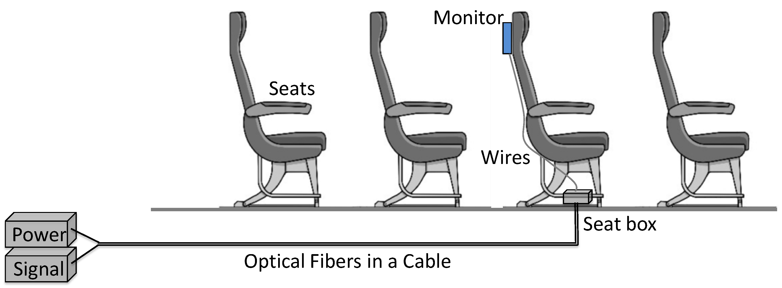
Figure 1 illustrates the signal information and power connection scheme for individual assistance in an in-flight entertainment system. Using fiber to the seat (Fiber-to-the-Seat) could eliminate the intermediate boxes traditionally used in a system based on copper wires [
5]. In this scheme, the PoF power and the IFE information signal are transmitted by individual fibers to a transition box placed below the seat where the optical to electrical conversion of the PoF to the IFE takes place, going from there to the video monitor placed in the back seat. Multimode fibers with a 50-micron core are typically used in optical fiber-based IFEs.
In IFEC systems, Gigabit Passive Optical Networks (G-PON) schemes can also be used, which are currently widely used in telecommunications access networks [
3]. These networks are based on splitting the optical signal using optical couplers. The use of a power division scheme in PoF to serve several seats is highly desirable, but it brings challenges in using extremely high-power lasers, as well as fibers, connectors, and optical splitters that support high power. A large part of the damage at high power is attributed to the effects of power on glass-air interfaces, such as optical connector interfaces. Fiber-end-face damage is the main problem related to high-power transmission in optical fiber. In this effect, part of the optical power is absorbed by irregularities at the glass/air interface, generating heat and leading to catastrophic damage [
18,
19]. The theoretical CW damage threshold for the glass/air interface is ~ 1 MW/cm2. The threshold is 86.5 W for a 105-µm core, but the laser suppliers generally recommend a much lower safety value. In addition, optical fibers terminated with conventional connectors using epoxy to bond the optical fiber in the ferrule can suffer damage due to the high power. If part of the high-power is scattered into the ferrule, it can burn the epoxy, causing it to vaporize and deposit a residue on the face of the connector.
In this work, we study the IFE system based on the PoF system using an optical fiber length connecting a high optical source (HPOS) to an energy transformation unit (ETU), that represents the seat box in
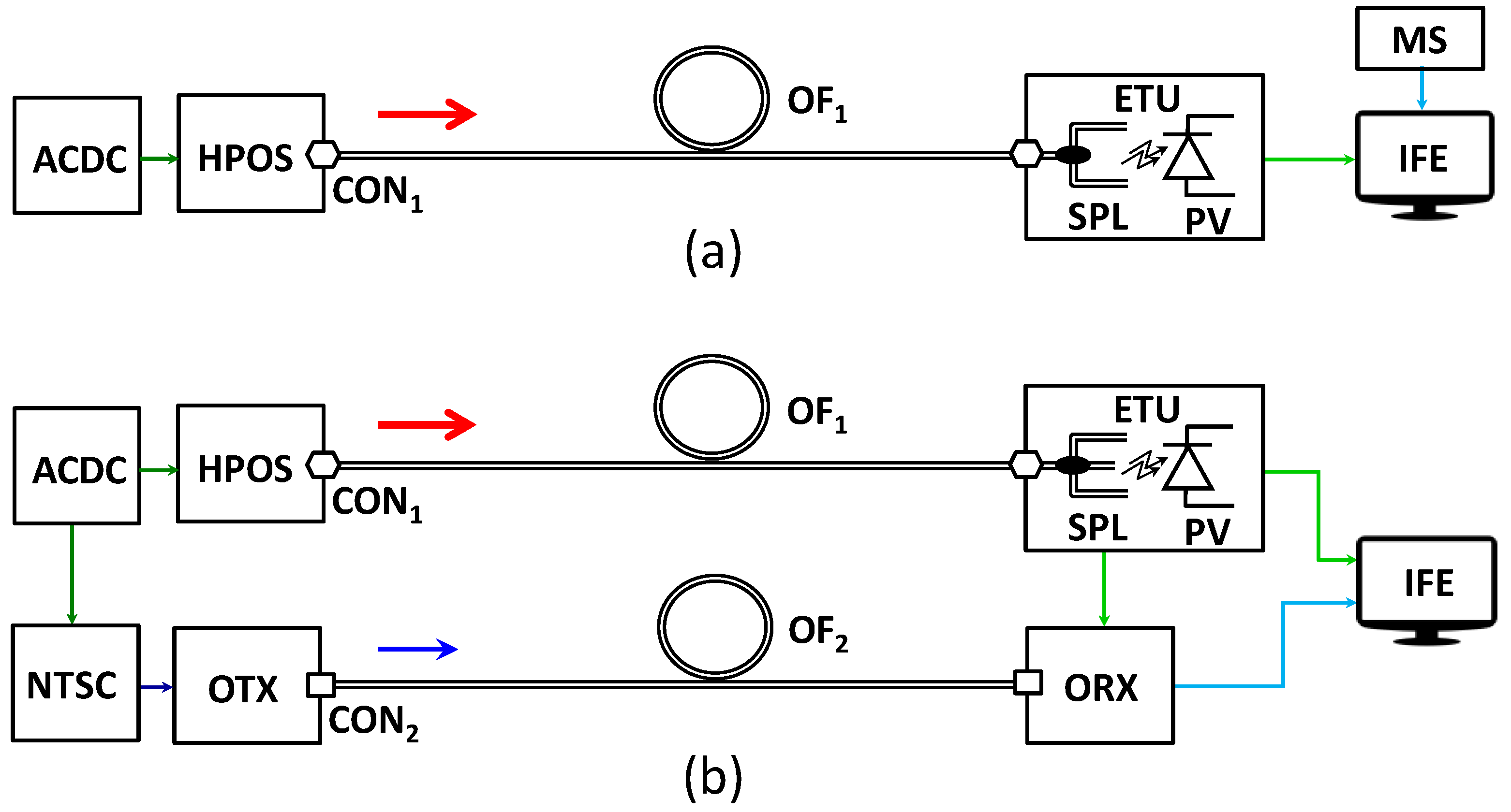
Figure 1. In
Figure 2(a) and
Figure 2(b), we showed the two PoF-IFE schemes studied in this work. In
Figure 2(a), the PoF-IFE system used a pre-loaded IFE and in
Figure 2(b), the PoF-IFE system used an extra fiber to transmit the video information to the IFE monitor.
An important aspect of PoF is the ETU's energy conversion scheme to meet different types of voltage, current, and power consumption.
Figure 3 shows two configurations of ETU used in this work, containing splitters and PVs to obtain voltage and current levels necessary for a specific load power [
10]. Furthermore, PVs must be specified regarding their maximum optical input power. Above this power, the efficiency of these devices drops with the increase in temperature caused by high power [
20,
21].
2.1. Design of PoF Systems and Circuits for IFE and the Specificaton of Devices
Using the PoF power budget equations described in [
10], we can evaluate the real possibility of this application for both schemes shown in
Figure 2 using the ETU types of
Figure 3. According to [
10], we have:
The PPV is the optical power in the PV input in W, PLoad is the electrical power of the load, ηPV is the PV efficiency, PHPOS is the HPOS output power, L is the fiber length in km, αFiberdB is the fiber attenuation in dB/ km, αConndB is the total connector loss, and αSpdB is the total splitter loss.
Considering the specification to use off-the-shelf devices in this work, we adopted the specifications of similar commercial video monitors but for other applications. The first one with 2.2 W of power consumption [
22] for a scheme of
Figure 2(b) and a digital picture frame for the scheme of
Figure 2(a) (model IT-Blue Max-703 from Alinee) and an optical receiver of 2.5 W [
23]. We will calculate the link power budget using commercial PVs made with materials available nowadays, GaAs and Si. The parameters for the link calculation are PV efficiency, that for GaAs PV is 50% (@808 nm) [
24,
25] and for Si PV is 26.8% (@975 nm) [
26]. The other parameters are α
FiberdB = 2 dB/km @ 808 nm and 1.6 dB/km @ 975 nm [
27], L = 50 m, α
ConndB = 0.5 dB [
28] and α
SpdB = 1.2 dB [
29]. Using these values in the equations (1) to (5) results in the values in
Table 1 and
Table 2. The power budget of the video communication link will not show because it is a commercial transmission and receiver kit [
23]. This system allows the transmission of NTSC, PAL, and SECAM video signals in a digital way.
Table 1 and
Table 2 summarize the power budget calculations for PoF-IFE link schemes of
Figure 2(a) and (b) and for ETU schemes of
Figure 3(a) and (b).
We specified the HPOS with a 15-W laser module at 808 nm [
30] for both types of PoF links. For the high power measurements detailed in the next section, we used an optical power meter, model 1835-C, and detector 818T-30/CM from Newport.
In the video optical link, we used a 62.5-micron optical fiber operating in the wavelength of 1310 nm and the maximum distance of operation of the commercial transmission and receiver kit is 500 m.
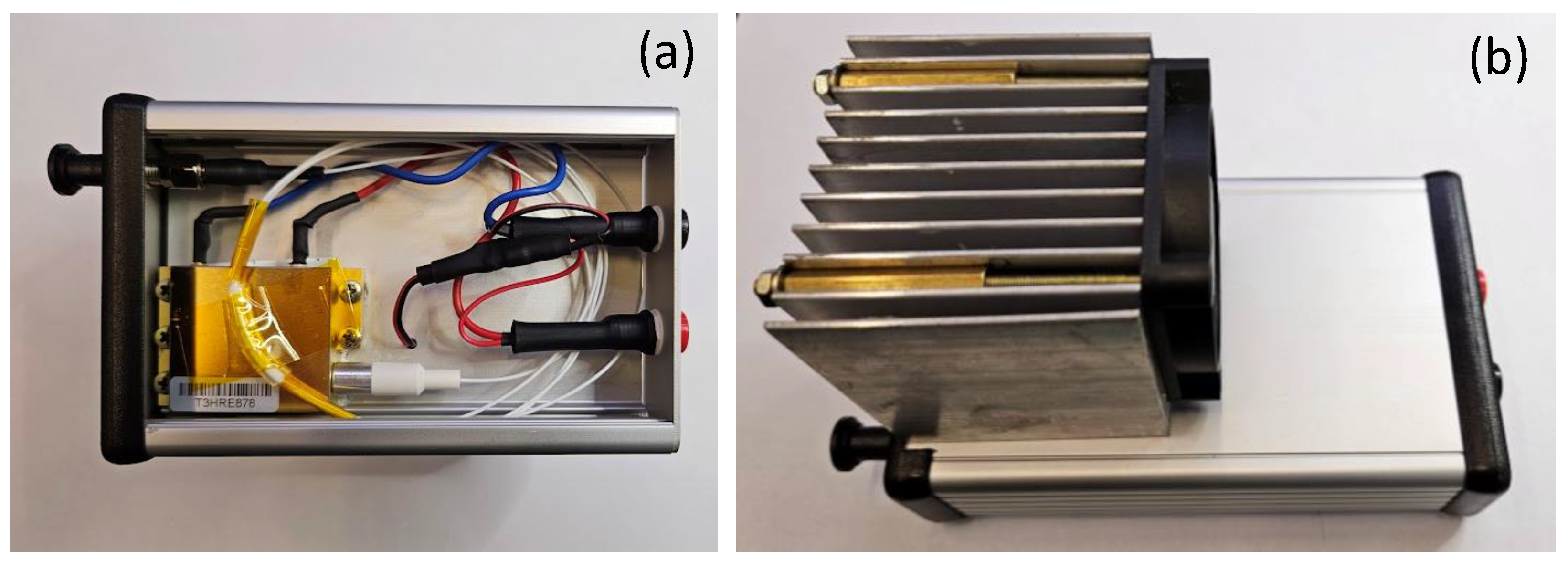
Figure 4(a) shows the laser assembling in an aluminum box (HPOS). The laser case is mounted internally in the top plate. A heat sink and a fan (
Figure 4(b)) are used on the external side to reduce the temperature of the laser.
Figure 5(a) and
Figure 5(b) show the ETU assembling in an aluminum box for the ETU-1 and ETU-2 respectively. In the ETU-1, we used the PV model AFBR-POC406L [
24]. For this model, the maximum input power is 1.5 W. In the ETU-2, we used the PV model AFBR-POC306A1 [
25]. For this model, the maximum input power is 6.0 W. The PVs are mounted internally on the top plate to reduce the temperature. In the assembling shown in
Figure 5(a), each splitter was connected with the other using splices. These splitters have a fiber diameter of 220 microns and because of this, the splices have to be done using a special machine splicer, which in this case was the splicer model Fujikura FSM-100P. An important comment about it is that is very difficult to find in the marked splices machines that made splices for optical fibers with diameters larger than 125 microns. In addition, the exact point of arc fusion must be tested to find the exact arc level before the splices are done. The splitters were also mounted internally in the top plate to reduce the temperature inside them.
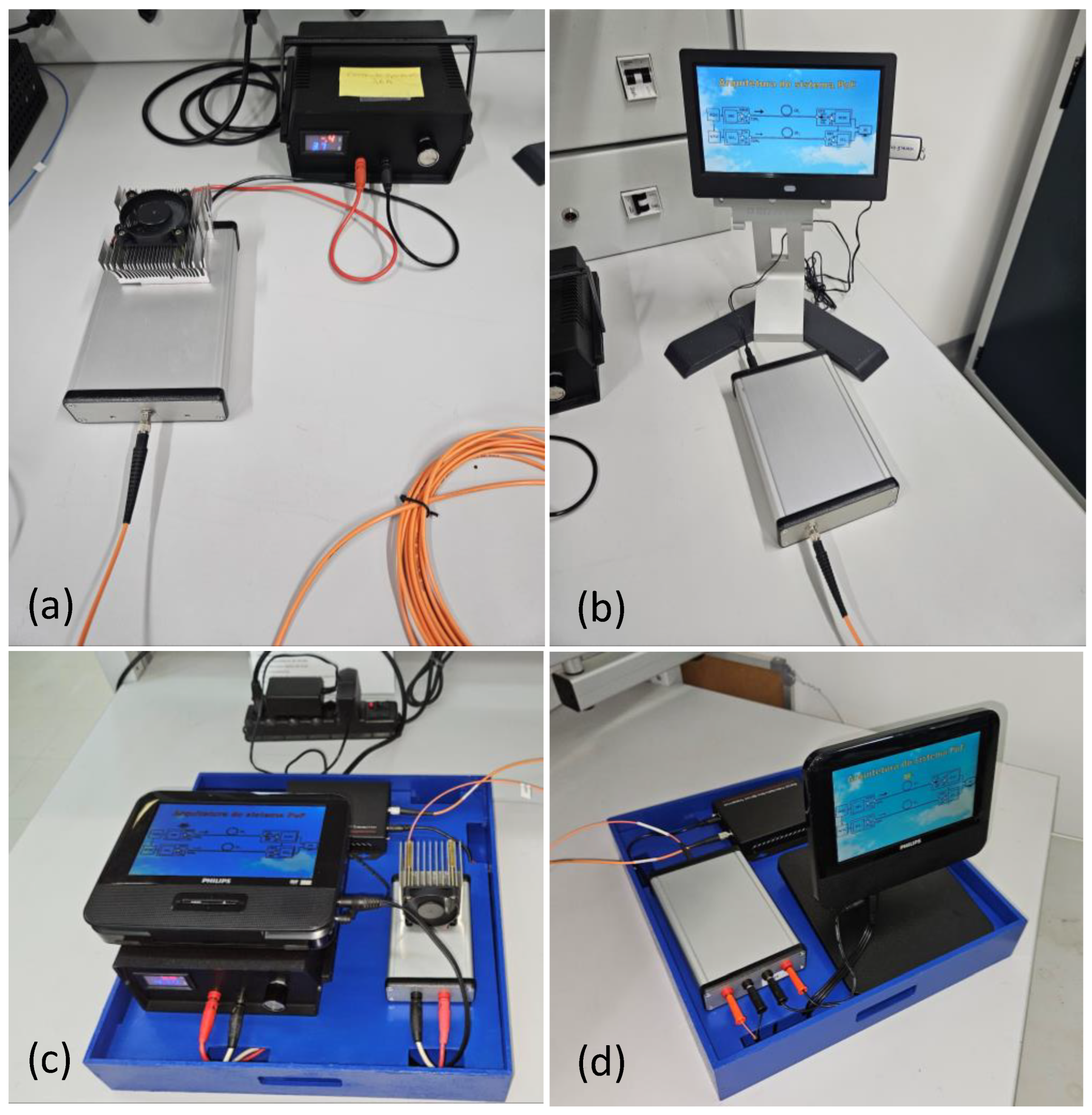
Figure 6 shows the transmission and reception parts of schemes of
Figure 2.
Figure 6(a) and (c) correspond to the power transmitter side and
Figure 6(b) and 6(d) correspond to the power receiver side.
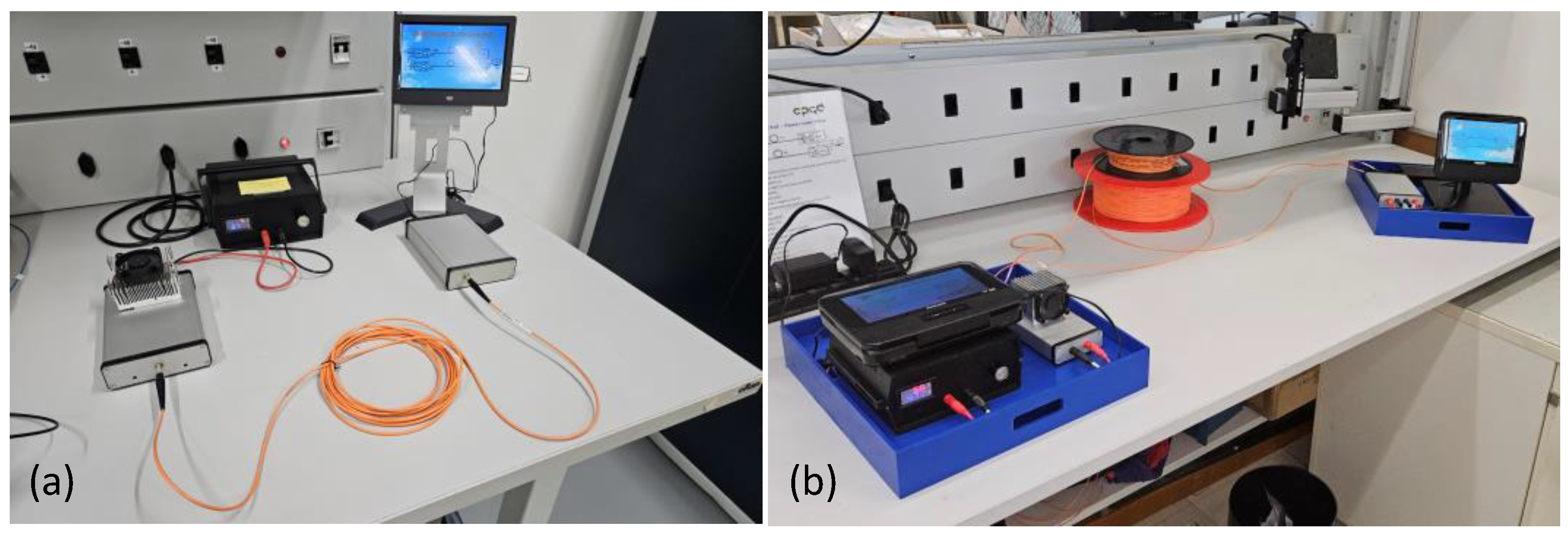
Figure 7 shows the PoF-IFE systems studied, where (a) is the PoF-IFE system using pre-loaded IFE and (b) is the PoF-IFE system using an extra fiber to transmit the video information to the IFE monitor.
3. Results
In this section, we will show the results of ETU characterization and the performance of the PoF-IFE systems. We clarify that only ETU-1 was initially evaluated. Based on the results obtained, we began to evaluate ETU-2.The ETU-1 (
Figure 3(a)) presented an insertion loss (1 connector, 2 splices, and 2 splitters) of 4.13 dB, which is 0.76 dB worse than the theoretical value used in the power budget calculation. The ETU-2 (
Figure 3(b)) presented an insertion loss (1 connector and 1 splitter) less than 0.5 dB, which is 1.7 dB better than the theoretical value used in the power budget calculation.
Figure 8(a) and 8(b) show the electrical power versus load characterization for ETU-1 and ETU-2 respectively.
Figure 9(a) and 9(b) show the optimum load versus optical power characterization for ETU-1 and ETU-2 respectively.
Figure 8 and
Figure 9 show an important characteristic of PV, that is, for a given load or optical input level, the electric output is maximum at that point. At that point, there is only one particular combination of current and voltage and therefore, only one optimum load resistance [
31]. It is possible to use a regulating of voltage or operate at or close to electric output maximum by using MPPT (Maximum Power Point Tracking) [
31], which is a logical electronic circuit whose function is to track the highest power point of the photovoltaic array to which it is connected and in a constant way. In PoF systems, the power transfer efficiency from the PVs depends on the amount of available light, temperature, and the electrical characteristics of the load. As these conditions vary, the optimum load characteristic that gives the highest power transfer also changes. In MPPT, the circuits can be designed to present optimal loads to the PVs.
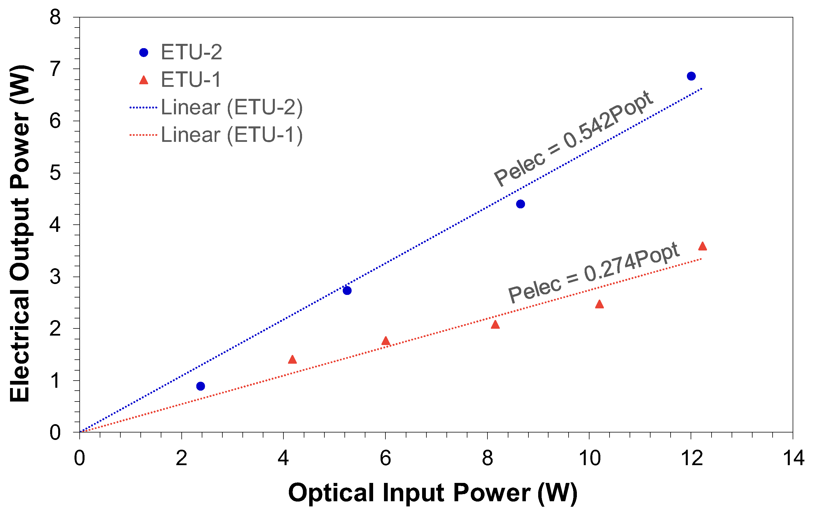
Figure 10 shows the electrical output power versus optical input power characterization, for ETU-1 and ETU-2. It can observed that the ETU-2 is approximately twice as efficient as ETU-1. This is expected due to the use of two splitters and respective fiber splices that caused the increase in the insertion loss and consequently, the reduction in the power delivered to the PVs.
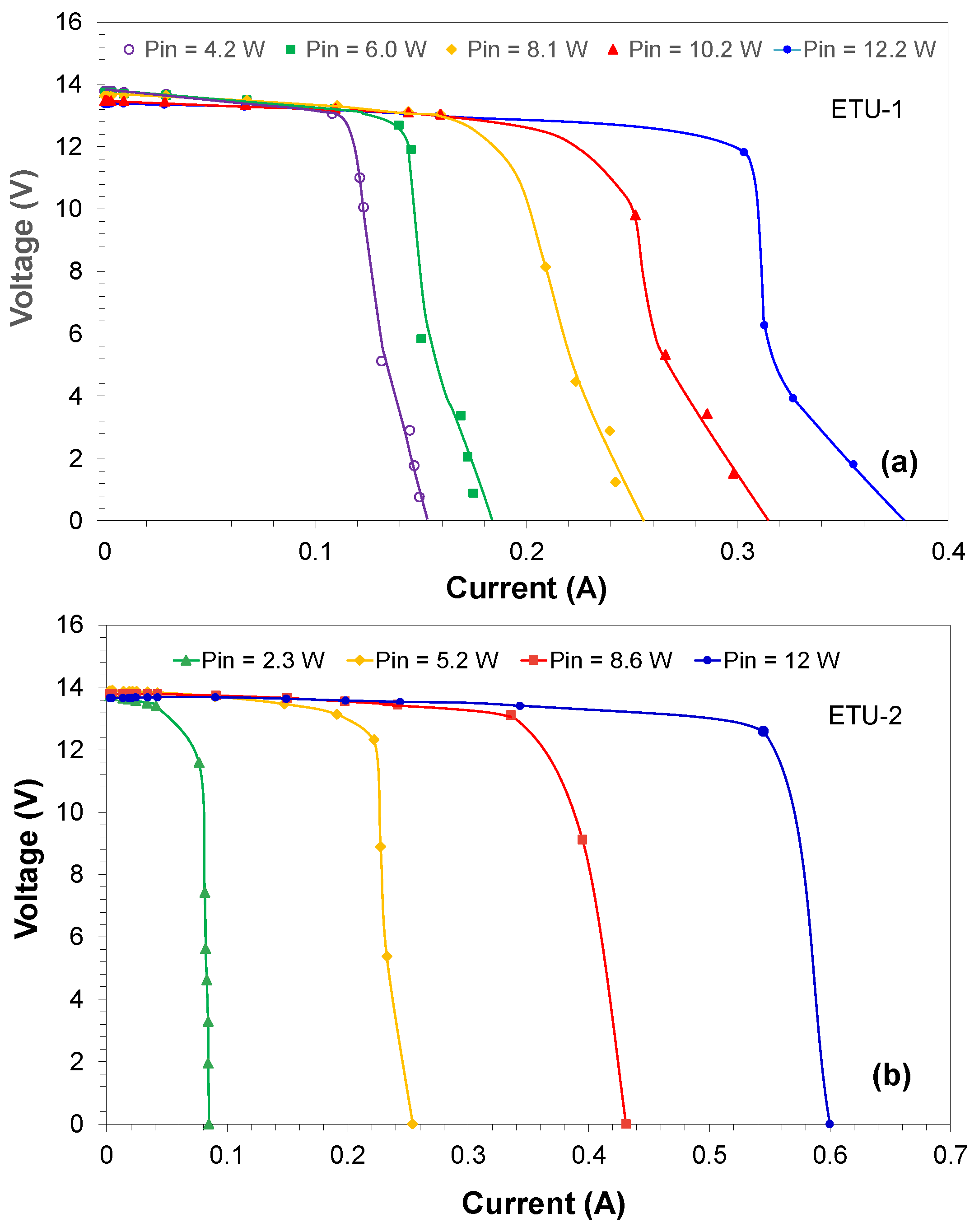
Figure 11(a) and 11(b) show the voltage versus current characterization at some optical input power levels for ETU-1 and ETU-2, respectively. Considering the nominal power of the IFE monitors, ETU-1 has power only to attend the preload IFE system (2.2 W) and the ETU-2 can attend the IFE system with the IFE monitor and optical receiver. The voltage versus current curve for ETU-1 is typical of PVs fabricated with 4 or 5 PN junctions [
32] and ETU-2 is typical of PVs fabricated with 6 PN junctions [
20].
The PoF-IFE systems using pre-loaded IFE and PoF-IFE systems using an extra fiber to transmit the video information to the IFE monitor work for many hours and the performance was according to the expectation. No degradation of video quality was observed in this period. In the first one, the HPOS operated with PHPOS = 10 W, and in the second one with PHPOS = 12 W. The maximum temperature reached on the PV case for ETU-2 was 50°C. A supplementary short video is available online regarding these PoF-IFE systems working at our laboratory.
4. Discussion
In search of weight reduction in aircraft, we proposed in this work the use of optical fibers to transmit a video signal and energy to replace the part of the copper cables still used for this purpose specifically for in-flight entertainment systems. To demonstrate this concept, some calculations of power-over-fiber links for aircraft applications were demonstrated. Parameters from commercial elements were used, such as high-power lasers, PVs, connectors, fibers, and splitters. However, given the first practical demonstration (proof of concept) and availability, for the IFE video monitors we used simpler commercial elements and not necessarily the video monitors used commercially on aircraft. The direct consequence is the fact that in this proof of concept, the load power values are lower than in a commercial monitor specific to IFE, where the power is above 10 W [
33].
Two types of optical systems were proposed to demonstrate the proof of concept. In the first one, a PoF system is used to power a pre-loaded IFE. As we commented before, pre-loaded IFE refers mainly to airline-issued entertainment devices that are pre-loaded with entertainment content. In our demonstration, the pre-loaded IFE is different from that used in practice, since in commercial systems the pre-loaded IFE consists of a tablet that is not usually attached to the back of the seat. In the second approach, a PoF system is used to power and transmit online IFE video signals. In this approach, an extra fiber is necessary to transmit the information to the IFE monitor and corresponds to a new IFE generation technology. In both systems, we adopted a link distance of 50 m to simulate correctly a maximum distance from a transmission unit to a seat equipped with video monitors.
The studied and tested links were point-to-point, but to reduce the number of fibers used, a point-to-point topology would be interesting, such as a PON (passive optical network) system used in telecommunications. This configuration would allow the service of some seats with the same fiber but would require lasers with greater optical power, fibers with larger core diameters, and robust optical connectors, which would need a careful study from the point of view of high optical power usability.
During the initial tests developed in this work, it was necessary to disconnect and connect the optical connectors after shutting down the optical power. In some cases, the connector's end faces caught dust, which caused a total connector failure when high power was turned on. In this case, it was necessary to change them. In addition, as we commented before since the splitters used in the ETUs have fibers with 220 microns core diameter, it was very complex to splice them. Is important to observe that it is very difficult to find splice machines in the market that make splices for optical fibers, such as the splicer with diameter larger than 125 microns. In addition, the exact point of arc fusion intensity must be tested before the splices are made. The splitters and PVs were also mounted internally in the top plate to reduce the temperature.
On the other way, the assembling of the PVs, splitters, and input optical connectors in an aluminum box ensured that the temperature in the PVs did not exceed 50 °C. The maximum operating temperature of PVs is 85°C.
The analysis of the experimental results mainly shows that the use of more than one splitter substantially increases the intrinsic insertion loss, which leads to a loss of efficiency of the power transformation units. This was the case of ETU-1 where losses due to the connector, splices, and splitters were 4.13 dB. On the other hand, the ETU-2 losses (intrinsic) with only one splitter were less than 0.5 dB. Given these circumstances, the ETU-1 was choose be used in the pre-loaded PoF-IFE system with the HPOS operating at 10 W and the ETU-2 was chosen to be used in PoF-IFE system with additional fiber with the HPOS operating at 12 W. It is important to note that at this power level the PVs in each ETU operated with input optical power below the maximum allowed (1.5 W for ETU-1 and 6 W for ETU-2) [
24,
25].
5. Conclusions
Since the use of optical fibers is increasing in modern aircraft in sensing, control, and communication due to their high transmission capacity, better reliability, and immunity to electromagnetic interference, high-intensity radiated fields and lightning, this work presented a new functionality in aircraft, the optical fiber to replace part of copper cables to transmit power. Specifically, this work described a video and power transmission system using optical fibers for in-flight entertainment (IFE) system application. We described the benefits and the limitations of this application and we performed two practical experiments to demonstrate it. It used off-the-shelf devices, such as 15-W semiconductor lasers operating at 808 nm, GaAs photovoltaic converters, optical transmitter, optical receiver, and video monitors in the experiments. The power and video signals were transmitted using two 50-m multimode fibers. In addition, we proposed and tested two types of energy transformation units (ETU) which are responsible for supplying electrical energy to the IFE video monitor and the optical fiber receiver.
The demonstration of PoF in IFE systems showed good results, although as we previously commented, the video monitors used present lower power consumption than those used in commercial aircraft. In addition, for future uses in aircraft are necessary optical connector more robust and a new design for the thermal management system.
However, this demonstration paves the way for the development of diverse aeronautical solutions in the most diverse systems, since the main characteristics of fiber optic technology have shown that this is an 'enabling element' for the future of aviation, where we will have a change of paradigms in aerodynamics, materials and massive electrification.
Supplementary Materials
The following supporting information can be downloaded at the website of this paper posted on Preprints.org. Video S1: Video showing the PoF-IFE systems working at our laboratory.
Author Contributions
Conceptualization, A.B.S. and J.B.R.; methodology, L.M.W.; validation, L.M.W. and M.P.O,; investigation, J.B.R., F.R.B.; resources, A.B.S.; data curation, J.B.R. and F.R.B..; writing—original draft preparation, J.B.R..; writing—review and editing, A.B.S., F.R.B., M.P.O. and L.M.W.; project administration, A.B.S..; funding acquisition, A.B.S. All authors have read and agreed to the published version of the manuscript.” Please turn to the CRediT taxonomy for the term explanation. Authorship must be limited to those who have contributed substantially to the work reported.
Funding
The authors thanks Embrapii grant PCPQ-2306.0111 and National Council for Scientific and Technological Development (CNPq), grants 440220/2021-1, 303791/2021-7 and 302755/2023-3.
Institutional Review Board Statement
Not applicable.
Informed Consent Statement
Not applicable.
Data Availability Statement
Data are contained within the article
Acknowledgments
The authors wish thanks to Carla C. Furoni for all administrative support and Pedro J. Nagano, Luiz A. R. Nerosky, Jose Juliano Fioretto and João Roberto Nogueira Junior all technical support.
Conflicts of Interest
The authors declare no conflict of interest.
References
- Careless, J., Trends and advances in embedded avionics systems: an ATR roundtable,” Aerospace TechReview, Oct 18, 2022. Available online: https://aerospacetechreview.com/trends-and-advances-in-embedded-avionics-systems-an-atr-roundtable/ (accessed on 06 May 2024).
- Engineering ToolBox (2001) Available online: https://www.engineeringtoolbox.com/density-solids-d_1265.html (accessed on 06 May 2024).
- Saadaoui, Hamza; Bacou, A.; Rebiere, Y.; Fracasso; B.; and Morvan. M. Broadband optical network design for the future aircraft cabin, Opt. Continuum 1, 719-737, 2022. [CrossRef]
- Bellamy III, W. On-Demand Cabins: The New In-Flight Entertainment, Avionics Today, 24 September 2015. Available online: https://interactive.aviationtoday.com/on-demand-cabins-the-new-in-flight-entertainment/ (accessed on 06 May 2024).
- Koon, J., How Fiber Optics Will Propel Future Avionics, Avionics Today, 24 January 2020. Available online: http://interactive.aviationtoday.com/how-fiber-optics-will-propel-future-avionics/ (accessed on 06 May 2024).
- Tameh, T. A.; Sawan, M. and Kashyap, R., Optical sensors for fly-by-light flight control systems, 2016 IEEE Avionics and Vehicle Fiber-Optics and Photonics Conference (AVFOP), Long Beach, CA, USA, pp. 295-296, 2016. [CrossRef]
- Algora, C.; García, I.; Delgado, M.; Peña, R.; Vázquez, C.; Hinojosa, M.; and Rey-Stolle, I., Beaming power: Photovoltaic laser power converters for power-by-light, Joule, Volume 6, Issue 2, Pages 340-368, 2022. [CrossRef]
- Mohammadnia, A.; Ziapour, B. M.; Ghaebi, H., Khooban, M. H., Feasibility assessment of next-generation drones powering by laser-based wireless power transfer, Optics & Laser Technology, Volume 143, 107283,2021. [CrossRef]
- Natsuki, S.; Kobatake, T., Masson, D., Fafard, S. and Matsuura, M., Optically Powered and Controlled Drones Using Optical Fibers for Airborne Base Stations, Photonics 9, no. 11: 882, 2022. [CrossRef]
- Rosolem, J. B., Power-over-fiber applications for telecommunications and for electric utilities, IntechOpen, 2017. [CrossRef]
- Matsuura, M., Recent Advancement in Power-over-Fiber Technologies, Photonics 8, no. 8: 335, 2021. [CrossRef]
- Sherman, B. D.; Mendez, A. J.; and Morookian, J. M.; Efficiency of a 5V/5-mW power by light power supply for avionics applications, Proc. SPIE 1369, Fiber Optic Systems for Mobile Platforms IV, 1 February, 1991. [CrossRef]
- Spillman, W. B.; Crowne, D. H.; Woodward D. W., Optically powered and interrogated rotary position sensor for aircraft engine control applications, Optics and Lasers in Engineering, Volume 16, Issues 2–3, Pages 105-118, 1992. [CrossRef]
- CORDIS, Final Report Summary - ASHLEY - Avionics Systems Hosted on a distributed modular electronics Large scale dEmonstrator for multiple tYpe of aircraft, Community Research and Development Information Service (CORDIS), 2017. https://cordis.europa.eu/project/id/605442/reporting/it.
- Rosolem, J. B.; Nogueira Júnior, J. R.; Bassan, F. R.; Furoni, C. C.; dos Santos; A. B.; Wollinger; L. M.; Nagano, P. J.; de Oliveira, M. P.; Nerosky, L. A. R.; and Fioretto, J. J., Power-over-Fiber Applied for In-Flight Entertainment System, In The 6th Optical Wireless and Fiber Power Transmission Conference (OWPT2024), Online/Venue hybrid, Japan, Apr. 23 - 26, 2024.
- Jin, M. J.; and Kim, J. K., Customer adoption factors for in-flight entertainment and connectivity, Research in Transportation Business & Management, Volume 43, 100759, ISSN 2210-5395, 2022. [CrossRef]
- Preston, A., The incredible evolution of in-flight entertainment, Key.Aero, 16 May, 2023. https://www.key.aero/article/incredible-evolution-flight-entertainment.
- Mann, G.; Jurke, M.; Zoheidi, M; Eberstein, M.; and Krüger, J., Influence of core diameter and coating material on nanosecond laser-induced damage threshold of optical multimode fibers, Journal of Optoelectronics and Advanced Materials Vol. 12, Iss. 3, pp. 711-714, 2010. [CrossRef]
- Seo, K.; Nishimura, N.; Shiino, M.; Yugushi, R.; and Sasaki, H., Evaluation of high-power endurance in optical fiber links,” Furukawa Review, 24:17-22, 2003.
- Fafard, S.; Masson, D. P., Perspective on photovoltaic optical power converters, J. Appl. Phys., 28 October, 130 (16): 160901, 2021. [CrossRef]
- Fafard, S. et al., High-Efficiency Photovoltaic Power Converters and Application to Optical Power Transmission, 26th Microoptics Conference (MOC), Hamamatsu, Japan, pp. 1-2, 2021. [CrossRef]
- Phillips, PD7012/37 - Philips Portable DVD Player, Available online: https://www.documents.philips.com/assets/20231202/651d40d8ab804c29b6a4b0cc01139fe4.pdf (accessed on 06 May 2024).
- Primeda-Telecom, JL-1V1A - Video/Audio/Data over Fiber Media Converters, Available online: http://www.primeda-telecom.com/product_view_746.html (accessed on 06 May 2024).
- Broadcom, AFBR-POC406L - Optical Power Converter 6VDC, ST Port, Available online: https://www.broadcom.com/products/fiber-optic-modules-components/industrial/optical-power-components/optical-power-converters/afbr-poc406l (accessed on 06 May 2024).
- Broadcom, “AFBR-POC306A1 - Optical Power Converter 3W, ST Port, Available online: https://www.broadcom.com/products/fiber-optic-modules-components/industrial/optical-power-components/optical-power-converters/afbr-poc306a1 (accessed on 06 May 2024).
- MH GoPower, YCH-H003 - A novel electrical power delivery technology/YCH Series MIH Photovoltaic Power Converter, Available online: http://www.mhgopower.com/laser_pof_YCHPPC.html (accessed on 06 May 2024).
- Thorlabs, FG105LCA-CUSTOM - 0.22 NA Silica Core, Glass Clad Multimode Optical Fiber, Step Index, Available online: https://www.thorlabs.com/newgrouppage9.cfm?objectgroup_id=6838&pn=FG105LCA (accessed on 06 May 2024).
- Thorlabs, Step-Index Multimode Fiber Optic Patch Cables: SMA to SMA, Available online: https://www.thorlabs.com/newgrouppage9.cfm?objectgroup_id=351 (accessed on 06 May 2024).
- Thorlabs, TM105SS1B - Fiber Optic Couplers for Optogenetics, Available online: https://www.thorlabs.com/newgrouppage9.cfm?objectgroup_id=7800&pn=TM200SS1B (accessed on 06 May 2024).
- Skyera, TY-808+/-03NM-15.0W-25C-105-0.22NA -15W - 808nm 105 um Multi-function Laser Diode Module, Available online: http://www.skyeralaser.com/products_show.asp?s_id=361 (accessed on 06 May 2024).
- Broadcom, Optical Power Components Optimizing Optical Power Converter Output, Application Note. Available online: https://docs.broadcom.com/doc/AFBR-POCxxxL-AN (accessed on 06 May 2024).
- Fafard, S.; Proulx, F.; York, M. C.; Richard, L. S.; Provost, P. O.; Arès, R., Aimez, V.; and Masson, D. P., High-photovoltage GaAs vertical epitaxial monolithic heterostructures with 20 thin p/n junctions and a conversion efficiency of 60%. Applied Physics Letters, 109(13), 2016. [CrossRef]
- AeroExpo, Plugin Displays, Available online: https://pdf.aeroexpo.online/pdf/rosen-aviation/catalog-2011/173330-721.html#open6118 (accessed on 06 May 2024).
Figure 1.
Signal and power connection diagram for individual service in an in-flight entertainment system.
Figure 1.
Signal and power connection diagram for individual service in an in-flight entertainment system.
Figure 2.
PoF-IFE systems schemes studied in this work. (a) PoF-IFE system using pre-loaded IFE and (b) the PoF-IFE system using an extra fiber to transmit the video information to the IFE monitor. The blocks identifications are: ACDC- alternate to continuous electrical power supply, HPOS - high power optical source, NTSC – video generator, OTX – optical transmitter, CON1 – HPOS optical connector, CON2 – OTX optical connector, OF1 – optical fiber to PoF, OF2 – optical fiber to video transmission, ETU – energy transformation unit, SPL – splitter, PV – photovoltaic converters, ORX – optical receiver, IFE – in-flight entertainment monitor, MS – memory stick.
Figure 3.
ETU schemes studied in work. (a) ETU-1: three splitters connected in series dividing the input power in four branches that powering two PVs connected in series with two in parallel, and (b) ETU-2: one splitter dividing the input power in two branches powering two PVs connected in series.
Figure 3.
ETU schemes studied in work. (a) ETU-1: three splitters connected in series dividing the input power in four branches that powering two PVs connected in series with two in parallel, and (b) ETU-2: one splitter dividing the input power in two branches powering two PVs connected in series.
Figure 4.
(a) laser assembling in an aluminum box and (b) heat sink and a fan used in the external side to reduce the temperature of the laser.
Figure 4.
(a) laser assembling in an aluminum box and (b) heat sink and a fan used in the external side to reduce the temperature of the laser.
Figure 5.
(a) ETU assembling for the scheme of
Figure 3(a) and (b) ETU assembling for the scheme of
Figure 3(b).
Figure 5.
(a) ETU assembling for the scheme of
Figure 3(a) and (b) ETU assembling for the scheme of
Figure 3(b).
Figure 6.
(a) ACDC- electrical power supply, NTSC – video generator, OTX – optical transmitter, and HPOS – high power optical source, (b) ETU-1 – energy transformation unit and IFE – in-flight entertainment monitor, (c) ACDC- electrical power supply and HPOS – high power optical source (d) ETU-2 – energy transformation unit, ORX – optical receiver and IFE – in-flight entertainment monitor.
Figure 7.
PoF-IFE systems including all the elements.
Figure 7.
PoF-IFE systems including all the elements.
Figure 8.
Electrical power versus load characterization, for: (a) ETU-1 and (b) ETU-2.
Figure 8.
Electrical power versus load characterization, for: (a) ETU-1 and (b) ETU-2.
Figure 9.
Optimum Load versus optical input power characterization, for: (a) ETU-1 and (b) ETU-2.
Figure 9.
Optimum Load versus optical input power characterization, for: (a) ETU-1 and (b) ETU-2.
Figure 10.
Electrical output power versus optical input power characterization, for: ETU-1 and ETU-2.
Figure 10.
Electrical output power versus optical input power characterization, for: ETU-1 and ETU-2.
Figure 11.
Voltage versus current characterization, for ETU-1 and ETU-2.
Figure 11.
Voltage versus current characterization, for ETU-1 and ETU-2.
Table 1.
Link power budget para o PoF-IFE system using pre-loaded IFE.
Table 1.
Link power budget para o PoF-IFE system using pre-loaded IFE.
| Parameter |
ETU-1 |
ETU-2 |
| PV type |
Si (975 nm) |
GaAs (808 nm) |
Si (975 nm) |
GaAs (808 nm) |
| Load Consumption (W) |
2.2 |
2.2 |
2.2 |
2.2 |
| PV efficiency (%) |
26.8 |
50 |
26.8 |
50 |
| PPV (W) |
8.2 |
4.4 |
8.2 |
4.4 |
| PV quantity |
4 |
4 |
2 |
2 |
| Power by PV |
2.05 |
1.1 |
4.1 |
2.2 |
| αFiber (dB/km) |
1.6 |
2.0 |
1.6 |
2.0 |
| αConn (dB) |
1.0 |
1.0 |
1.0 |
1.0 |
| αSpl (dB) |
2.4 |
2.4 |
1.2 |
1.2 |
| PHPOS (W) |
18.3 |
9.8 |
13.3 |
7.4 |
Table 2.
Link power budget for the PoF-IFE system using an extra fiber to transmit the video signal to the IFE monitor.
Table 2.
Link power budget for the PoF-IFE system using an extra fiber to transmit the video signal to the IFE monitor.
| Parameter |
ETU-1 |
ETU-2 |
| PV type |
Si (975 nm) |
GaAs (808 nm) |
Si (975 nm) |
GaAs (808 nm) |
| Load Consumption (W) |
4.7 |
4.7 |
4.7 |
4.7 |
| PV efficiency (%) |
26.8 |
50 |
26.8 |
50 |
| PPV (W) |
17.5 |
9.4 |
17.5 |
9.4 |
| PV quantity |
4 |
4 |
2 |
2 |
| Power by PV |
4.3 |
2.3 |
8.7 |
4.7 |
| αFiber (dB/km) |
1.6 |
2.0 |
1.6 |
2.0 |
| αConn (dB) |
1.0 |
1.0 |
1.0 |
1.0 |
| αSpl (dB) |
2.4 |
2.4 |
1.2 |
1.2 |
| PHPOS (W) |
39.0 |
20.9 |
29.7 |
15.9 |
|
Disclaimer/Publisher’s Note: The statements, opinions and data contained in all publications are solely those of the individual author(s) and contributor(s) and not of MDPI and/or the editor(s). MDPI and/or the editor(s) disclaim responsibility for any injury to people or property resulting from any ideas, methods, instructions or products referred to in the content. |
© 2024 by the authors. Licensee MDPI, Basel, Switzerland. This article is an open access article distributed under the terms and conditions of the Creative Commons Attribution (CC BY) license (http://creativecommons.org/licenses/by/4.0/).
