1. Introduction
Recently, problems such as fossil fuel depletion, environmental pollution, and global warming issues are becoming more serious every year. Interest in producing electricity from renewable resources and cases of its application are increasing [1-2]. Representative renewable resources include solar power and wind power. Wind power generation has the advantage of being environment-friendly, low production costs, and an infinite resource. Compared to solar power generation, wind power generation has the advantage of lower unit installation costs and lower production costs per unit for the same capacity [3-4]. Wind power generation systems are applied in a variety of ways, from small-scale power generation in urban areas to large-scale power generation in offshore areas [
5].
Generators using PM (Permanent Magnet) are widely used for wind power generators due to their advantages such as high torque density, high efficiency, and small size [6-8]. Small-scale PM generators have a simple structure and are often designed with a strong internal rotor. Generators require a tooth and slot structure to wind the coils on the stator. Due to the tooth structure, a spatial permeance difference occurs, which causes cogging torque. Since wind power exceeding cogging torque is required for the generator to operate, cogging torque reduction is necessary for the generator to operate in light winds [9-10].
Various studies are being conducted to reduce the cogging torque of wind power generators [11-13]. Since cogging torque is inversely proportional to the size of the LCM (least common multiple) of the number of poles and the number of slots, the cogging torque can be reduced by applying fractional slot concentrated winding (FSCW) with the number of slots per pole being 1 or less [14-15]. The cogging torque can be reduced by adjusting the spatial permeance difference through stator and rotor skew, the pole arc ratio of PMs, and tapering [16-21]. Research is also being conducted to reduce cogging torque by optimizing the length of the slot opening, which is the main cause of spatial permeability differences, or by adding magnetic wedges [22-23]. In order to reduce the cogging torque, the LCM is mainly changed by selecting the pole slot combination, or the generator shape design variables are optimized to reduce the spatial permeance difference.
In this paper, a new shape which is the straight shape of stator and permanent magnet is proposed to reduce cogging torque. The advantages of the proposed structure are discussed through comparison with the basic model which has the arc shape of stator and permanent magnet. By comparing pole slot combination for the proposed structure, the number of poles and slots with small cogging torque and high EMF characteristics is selected. Using ANSYS Maxwell, a finite element analysis (FEA) for electromagnetic design of proposed model is conducted and the final shape of proposed model is designed. Electromagnetic and structural simulations results of final model are shown, and comparison between the basic and final model is conducted. The final model of proposed generator was manufactured, and the comparison with FEA and experiment results is performed to verify the FEA.
This paper is organized as follows. In
Section 2, the specifications and proposed shape for the small wind generator are introduced. In
Section 3, the design method of proposed model is discussed. In
Section 4, manufactured model are introduced, and the experiment results are compared with the FEA results. Finally,
Section 5 presents the conclusion.
2. Specifications and Shape of Proposed Generator
2.1. Specifications of Generator
Small wind power generators require not only high efficiency and low THD (Total Harmonic Distortion) because it may be linked to the prevailing power source, but also low cogging torque for starting in light winds.
Table 1 shows the required specifications of the target small wind power generator.
2.2. Method for Reducing Cogging Torque
Cogging torque is energy variation according to magnet angular position. Because the energy change in the PM and core is negligible than airgap, the magnetostatic energy can be written as shown in Equation (1) [
24]:
where
μ0 is the permeability of air,
P(
θ) is the airgap permeance function,
Fm(
θ,
α) is the airgap MMF function,
α is the rotational angle of rotor,
Lstk is the stack length,
R1 and
R2 is PM and stator radius,
G(
θ) is the relative airgap permeance function, and
B(
θ) is the flux density function. Through Equation (1), the cogging torque can be derived as Equation (2):
where
NL is the LCM of the number of poles and slots,
GanNL and
BanNL is the design coefficient of stator teeth and PM. To reduce cogging torque, it is necessary to reduce
GanNL by changing the stator shape, such as teeth notching or asymmetric shoe, or
BanNL, by changing the rotor shape, such as PM shaping or adjusting the pole arc ratio. However, this method can significantly reduce EMF, output, and efficiency. In this paper, a new stator and rotor structure is proposed that significantly reduces cogging torque and does not reduce EMF significantly compared to basic structures.
2.3. Comparison of Base and Proposed Models
Figure 1a,b show the basic and proposed model of a small wind power generator. For comparison, the total usage of PMs for both models is same. The basic model, as shown in
Figure 1a, has a ring-type PM. It has a circular shoe shape to maintain a constant airgap length, but the permeance decreases sharply at the slot opening between the stator teeth which causes cogging torque. Considering the sudden change in spatial permeance, the proposed model as shown in
Figure 1b selected the PM as a straight shape. The shoe of the teeth was also changed to have a constant airgap length according to the shape of the PM. Due to these changes in the rotor and stator shapes, the two coefficients in Equation (2) change.
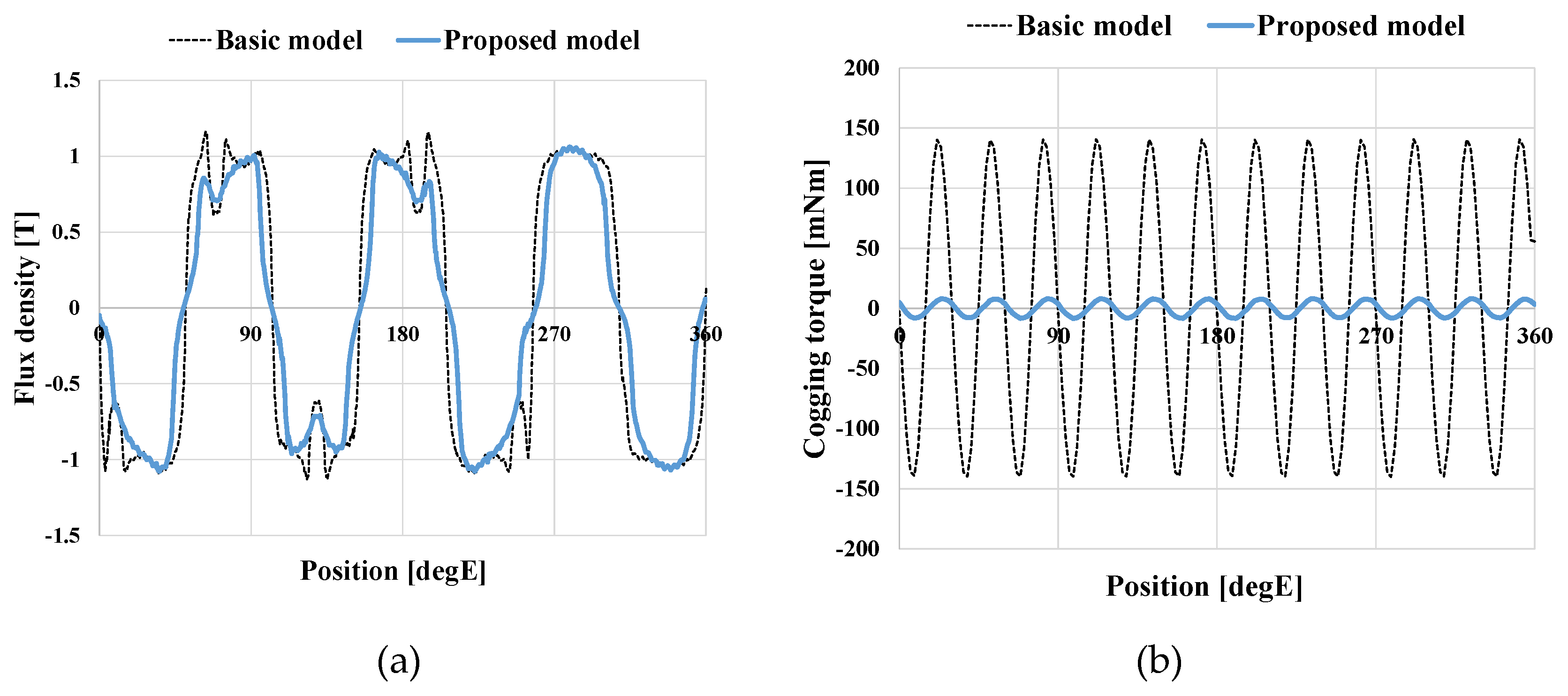
Figure 2 shows the waveforms of airgap flux density and cogging torque of the two models. As can be seen in
Figure 2a, the proposed model does not have large changes of airgap flux, and has smaller cogging torque characteristics than the basic model as shown in
Figure 2b.
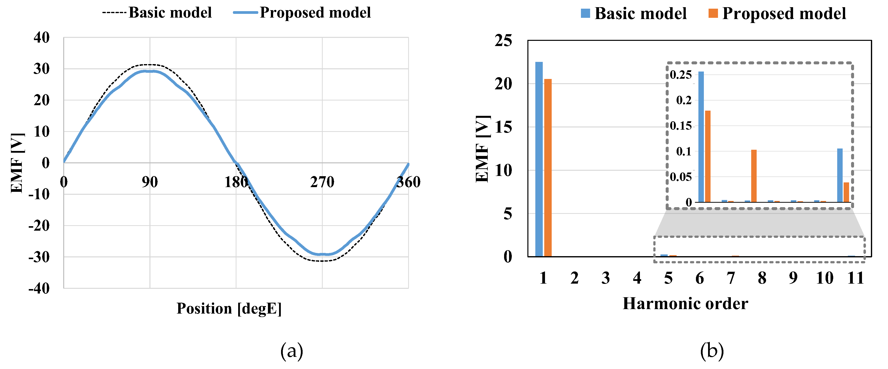
Figure 3 shows the EMF waveform and FFT results of the two models. As can be seen in
Figure 3, the basic model is superior in terms of EMF and THD characteristics.
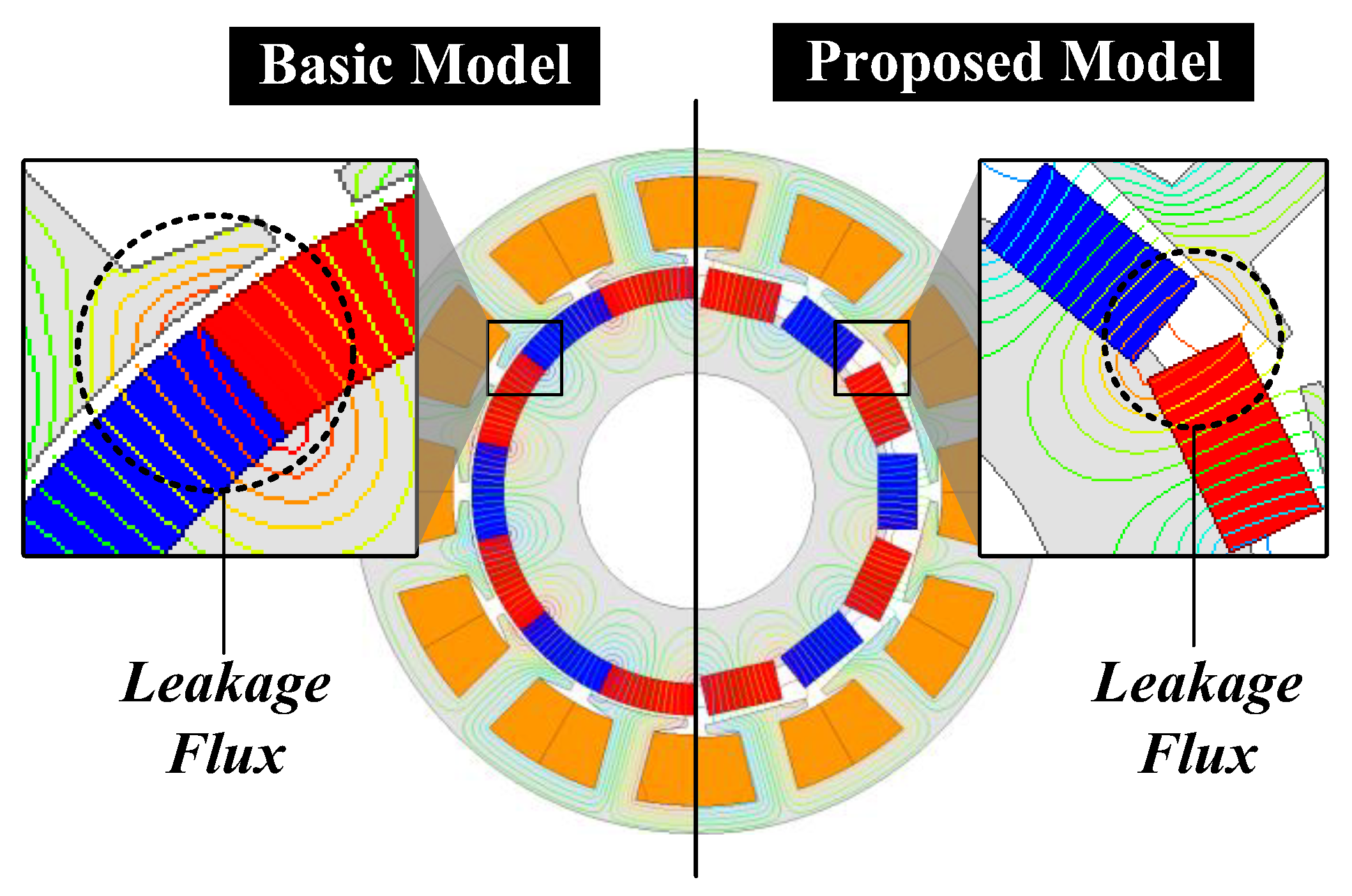
Figure 4 shows the flux lines of the basic and proposed models. As shown in
Figure 4, the basic model has large leakage flux between PMs, but the proposed model has a smaller leakage flux than basic model due to the gap between PMs. As shown in
Figure 3a,b, the EMF appears high because the length of the air gap is constant and small, but in the proposed model, the air gap length varies depending on the angular position and the average air gap length is larger than the basic model.
Table 2 shows the characteristics of the basic and proposed models. When the power is same, the efficiency of the proposed model is 0.2 %p less than the basic model. However, the THD of two models is same, and the cogging torque of the proposed model is significantly reduced compared to the basic model. In this paper, the proposed model was selected to reduce cogging torque, and additional design is conducted to improve efficiency and THD.
3. Electromagnetic Design of Proposed Wind Generator
3.1. Pole Slot Combinations
Wind power generators generally adopt fractional slot concentrated winding (FSCW), where the number of slots per pole per phase is less than 1 for small cogging torque and high power density.
Table 3 shows the winding factor according to pole slot combination. The pole slot combination with a high winding coefficient must be selected to achieve high power density. As shown in Equation (2), the other factor is the LCM of the number of poles and slots. The higher number of the LCM, the smaller the cogging torque appears [
25]. In this paper, generally used representative pole slot combination (10P12S, 14P12S, 14P18S, and 16P18S) were selected, and the corresponding EMF, THD, and cogging torque characteristics were confirmed. For equal comparison, the amount of PMs used and the equivalent number of turns for each model were selected to be the same.
Figure 5 shows the characteristics according to the pole slot combination.
Figure 5 shows that the 14P12S model has high EMF, low THD and cogging torque. In this paper, the 14P12S combination was selected and shape variable design was performed.
3.2. Airgap
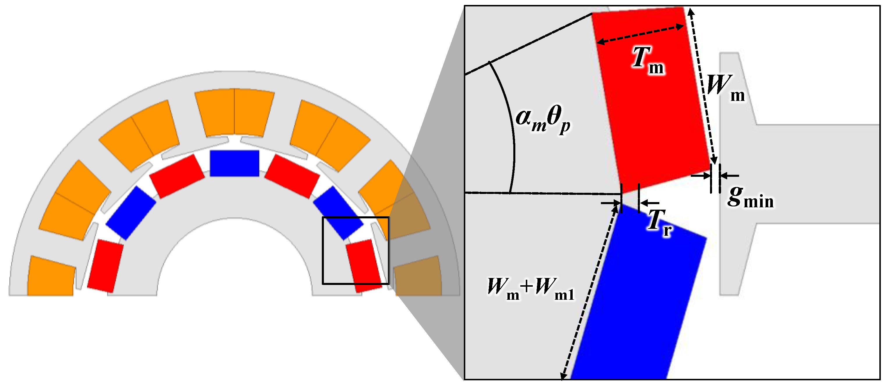
Figure 6 shows the design variables of the proposed model. In the proposed model, the PM has a straight shape, so the maximum rotor radius is from the origin to the PM vertex. Therefore, as shown in
Figure 6, the minimum airgap length (
gmin) from the PM vertex to the center of the shoe is selected.
3.3. Magnet
When the rotor outer diameter is fixed, the maximum PM width is determined by the PM thickness. Equation (3), (4) represent the PM width according to the rotor outer diameter and PM thickness, and is the maximum PM width that can be selected when the pole arc ratio is 1:
where
Wm is the PM width,
Tm is the PM thickness,
Dro is the rotor outer diameter,
αm is the pole arc ratio, and
Npole is the number of poles. As the PM thickness increases, the maximum width that can be selected decreases.
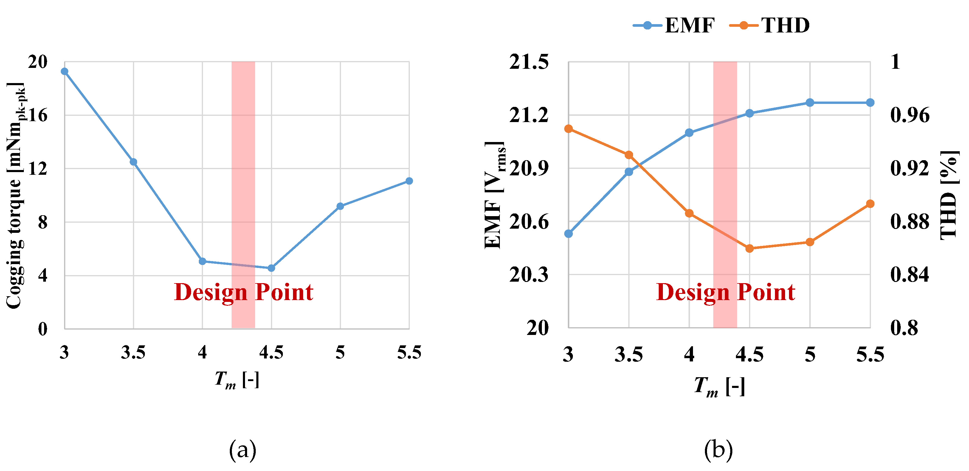
Figure 7 shows the characteristics of the proposed model according to PM thickness. As can be seen in
Figure 7a,b, design is required at a point where the cogging torque is minimum, the target EMF is satisfied, and the THD is small.
When inserting the PM of the proposed model into the rotor, if the PM has a rectangular shape, it may scatter when the generator is driven. Therefore, a structure is adopted in which the rotor core can support the PM through a small additional length (Wm1) about 0.2 mm of the inner side of the PM.
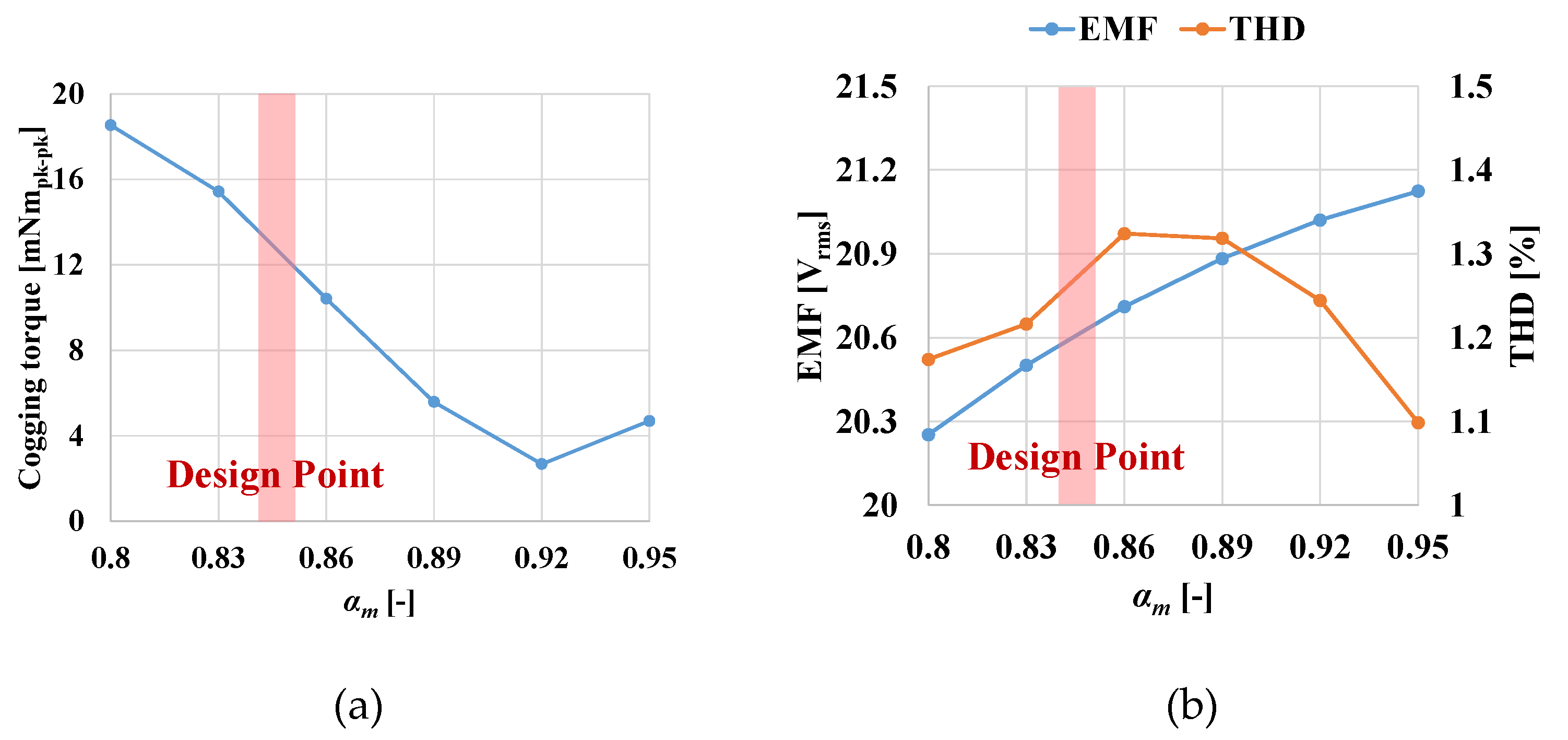
Figure 8 shows the characteristics of the proposed model according to the pole arc ratio. As can be seen in
Figure 8, as pole arc ratio increases, usage of PMs and EMF increases. Moreover, there is an optimal point for THD and cogging torque. The optimal design point is selected by considering the cogging torque, EMF characteristics, usage of PM, and constraints as shown in
Figure 8.
3.3. Rotor Core
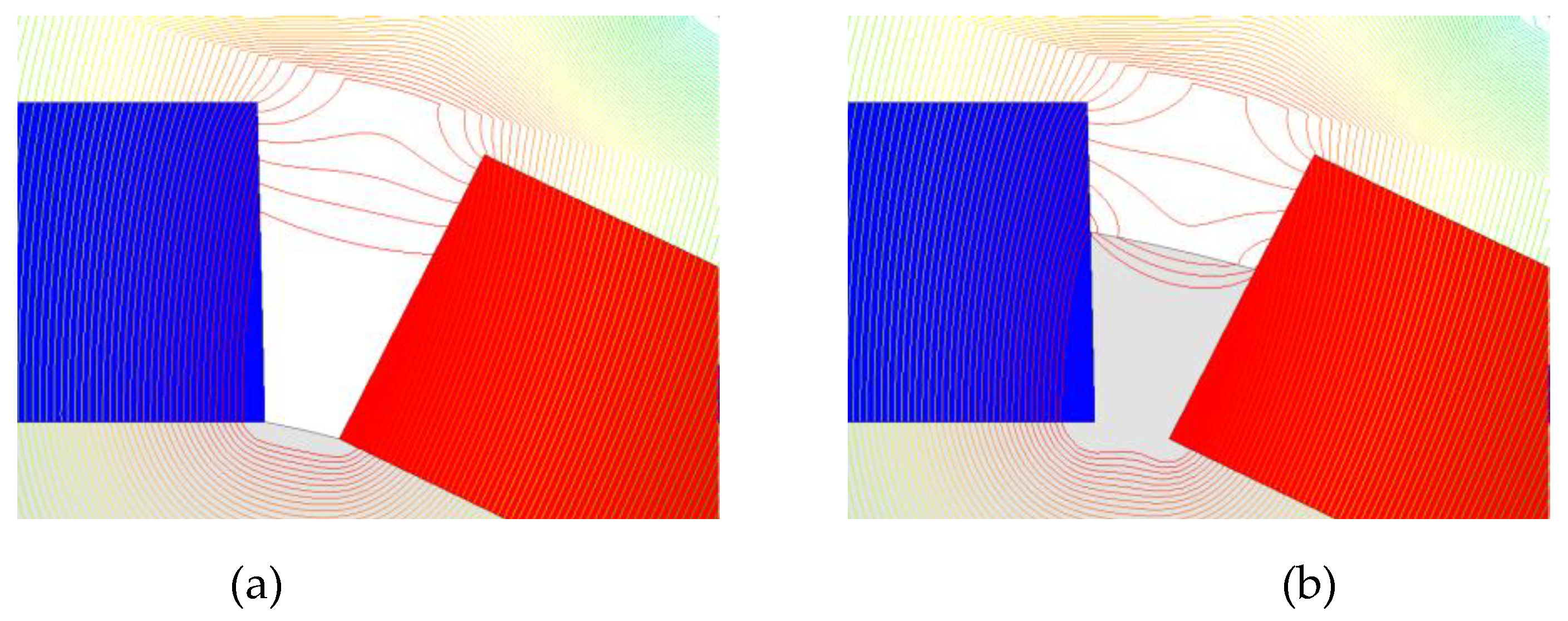
Figure 9 show the flux line according to the magnet insertion depth. In
Figure 9a, because of no iron between the PMs, the leakage flux between the PMs flows through air. In
Figure 9b, because of core between the PMs, leakage flux flows through iron. As can be seen in
Figure 9, when a PM is inserted into the rotor core, the electromagnetic characteristics may vary depending on the insertion depth because of leakage flux between the PMs. Because the average air gap length and leakage flux change depending on the PM insertion depth, there is an optimal point for cogging torque and EMF.
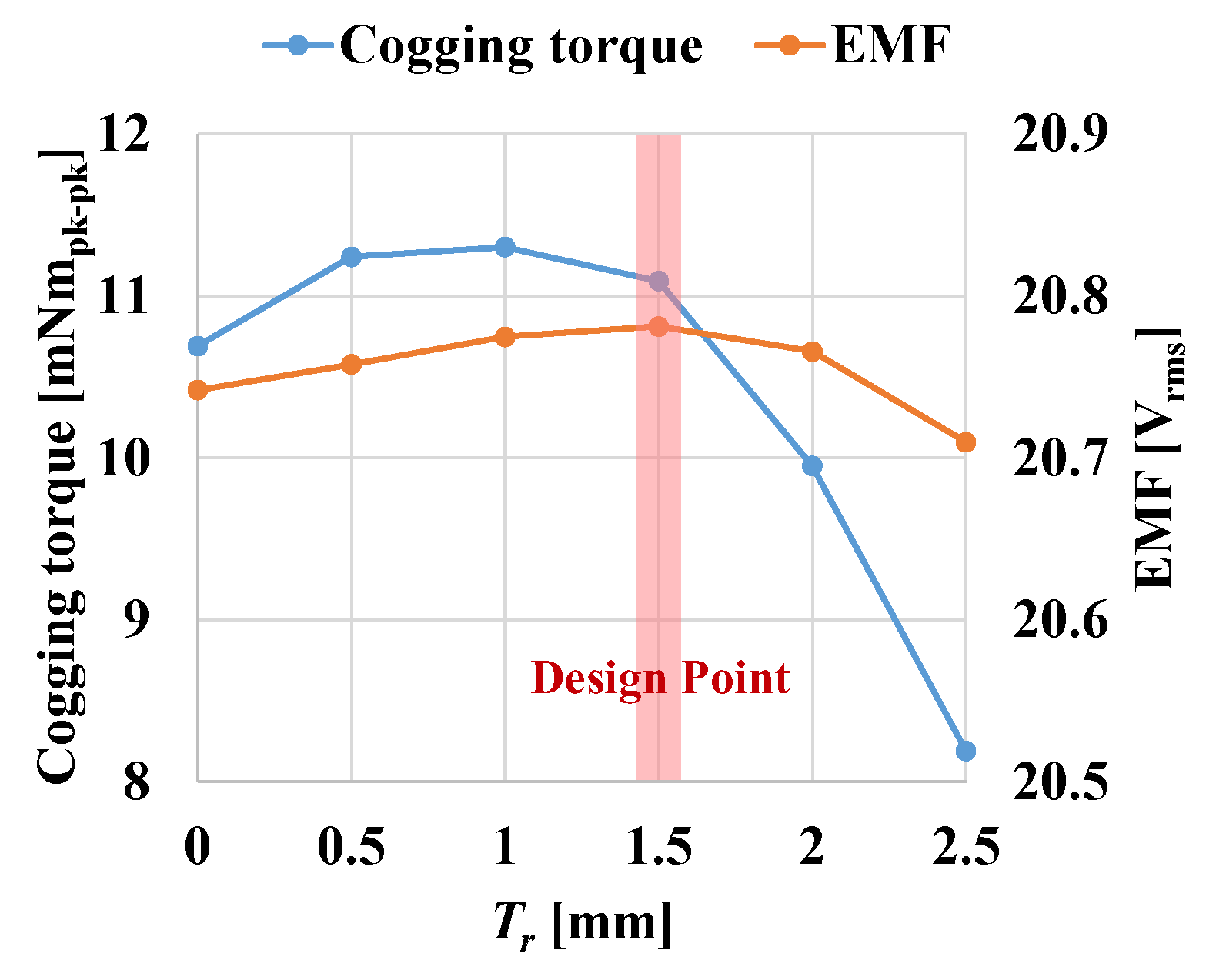
Figure 10 shows the cogging torque and EMF characteristics according to the PM insertion depth (
Tr). Because the average air gap length and leakage flux change depending on the PM insertion depth, there is an optimal point for cogging torque and EMF, as shown in
Figure 9. Considering design constraints, a point with high EMF and low cogging torque is selected.
3.4. FEA Results of Final Model
The design of the final model is carried out based on the design variable analysis conducted in the previous chapters.
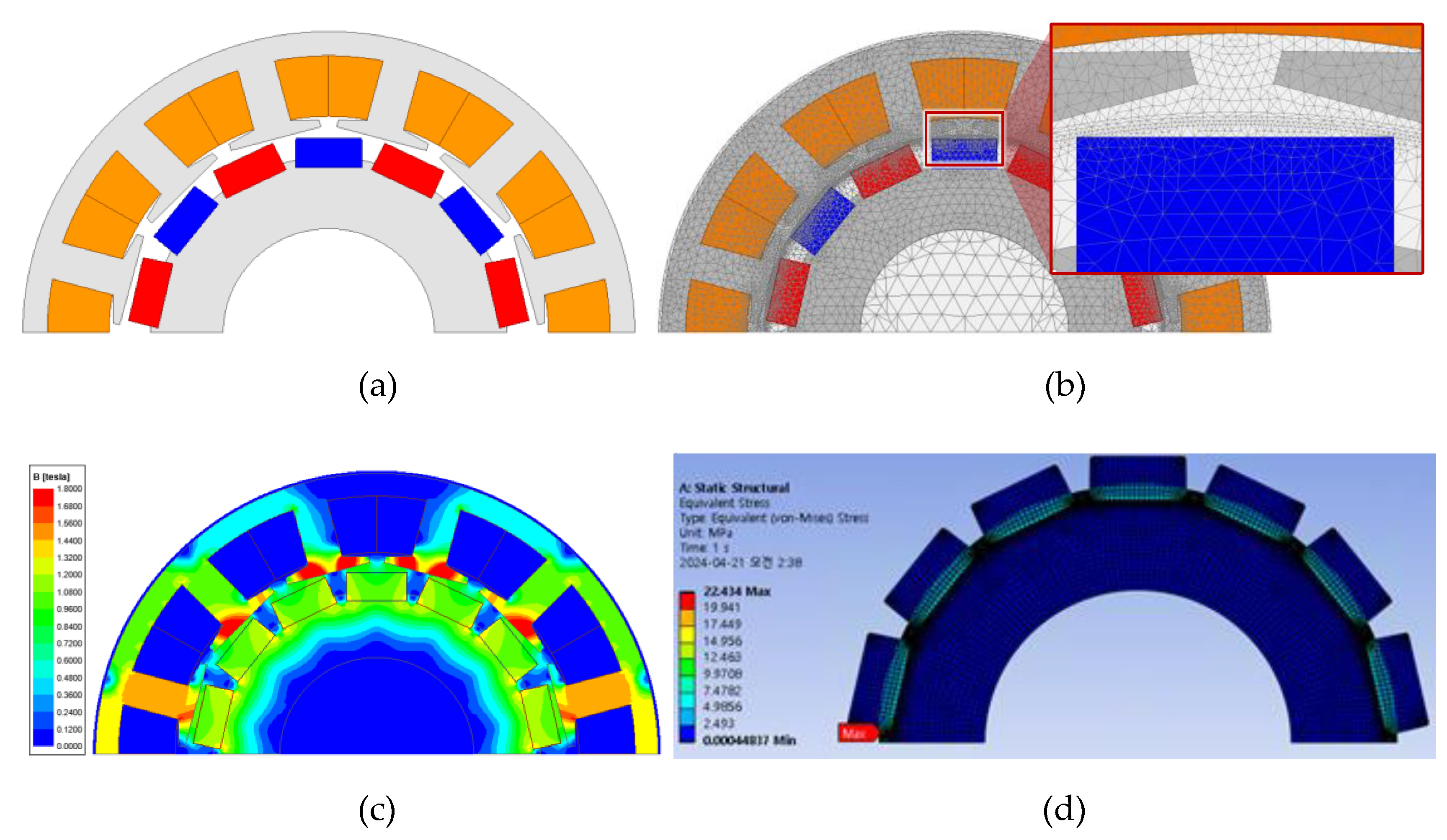
Figure 11a shows the final shape of the proposed model,
Figure 11b shows the mesh plot for FEA analysis, and
Figure 11c shows the magnetic flux density distribution. Since PMs may scatter due to stress when driving a generator, it is necessary to analyze the stress.
Figure 11(d) is the structural simulation result of proposed model rotor. In general, the safety factor is the index of the mechanical reliability and is calculated as equation (5) [
26]:
The safety factor is about 19.6, which confirms that it is safe from the stress.
Table 4 shows the design results of basic and final model. As can be seen in
Table 4, the size and output power of the two models are the same. In the final model, THD increased by 0.1%p and efficiency decreased by 0.2%p, but cogging torque was significantly reduced by 96% compared to the basic model.
4. Manufacture and Experiment Verification
To verify the FEA results, the prototype of final model was manufactured.
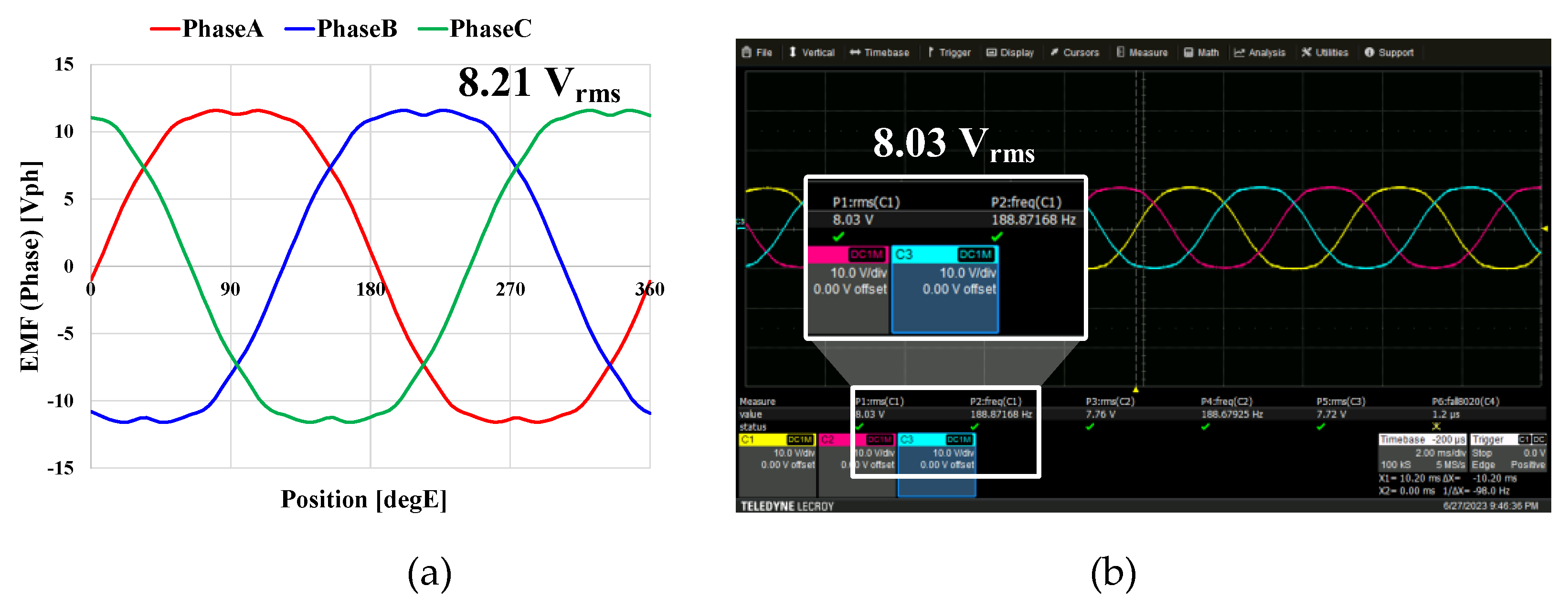
Figure 12 shows the manufactured prototype. Noload experiments were conducted on the prototype at 1600 RPM.
Figure 13 shows the prototype's EMF waveform of noload experiments. The FEA and experiment of EMF were 8.21V and 8.03V, respectively. Load experiments were conducted on the prototype at 2000 RPM. The value of the load resistance was adjusted so that the power of the generator was more than 150W. The output, terminal voltage, and efficiency were measured by load experiments.
Table 5 shows the FEA and experiment results of the wind power generator. As can be seen in
Table 5, for the same power, the terminal voltage and efficiency errors of both models are less than 1%.
5. Conclusions
This paper is about research on a new structure to reduce cogging torque of small wind power generators. Comparison between ring type and straight shape models is conducted to reduce cogging torque. For the proposed model, the number of pole and slot with smaller cogging torque are selected through comparison of pole slot combination. The design was conducted by reviewing the shape variables of the proposed model through FEA, and a final model with small cogging torque and high EMF was derived. A prototype was manufactured and experimented for the final model. The experiment results were verified by comparing them with the FEA results.
Author Contributions
Conceptualization, J.K. and H.K.; methodology, J.K.; software, J.D.; validation, J.K., H.H.; formal analysis, H.H.; investigation, J.K. and S.H.; resources, J.D.; data curation, J.D.; writing—original draft preparation, J.K.; writing—review and editing, Y.C. and J.L.; visualization, J.K.; supervision, H.K. and J.L.; project administration, J.K. and S.H.; funding acquisition, Y.C. and J.L. All authors have read and agreed to the published version of the manuscript.
Funding
This research was supported by Korea Electric Power Corporation. (Grant number: R22XO02-02) and in part by the Nano & Material Technology Development Program through the National Research Foundation of Korea(NRF) funded by Ministry of Science and ICT(2020M3H4A3106178).
Data Availability Statement
Not applicable.
Conflicts of Interest
The authors declare no conflicts of interest.
References
- Seangwong, P.; Chamchuen, S.; Fernando, N.; Siritaratiwat, A.; Khunkitti, P. A Novel Six-Phase V-Shaped Flux-Switching Permanent Magnet Generator for Wind Power Generation. Energies 2022, 15, 15–9608. [Google Scholar] [CrossRef]
- Seangwong, P.; Fernando, N.; Siritaratiwat, A.; Khunkitti, P. E-Core and C-Core Switched Flux Permanent Magnet Generators for Wind Power Generation. IEEE Access 2023, 11, 11–138601. [Google Scholar] [CrossRef]
- Kim,G. -H. Design and Characteristic Analysis of a 10 kW Superconducting Synchronous Generator for Wind Turbines. IEEE Trans. Appl. Supercond. 2013, 23, 23–5202405. [Google Scholar]
- Lee, S.-H.; Kim, Y. -J.; Lee, K. -S.; Kim, S. -J. Multiobjective Optimization Design of Small-Scale Wind Power Generator with Outer Rotor Based on Box–Behnken Design. 2016; 26. [Google Scholar]
- Manne, B.; Kiran Kumar, M. ; B. Akuru, U. Design and Performance Assessment of a Small-Scale Ferrite-PM Flux Reversal Wind Generator. 2020; 13. [Google Scholar]
- Li, J.; Yang, G.; Rao, F. Analysis and Design of Novel Axial Field Flux-Modulation Permanent Magnet Machines for Direct Drive Application. Machines 2022, 10, 10–495. [Google Scholar] [CrossRef]
- Jang, S.-M.; Park, H.-J.; Choi, J.-H.; Han, C.; Choi, M. -S. Analysis on the Magnetic Force Characteristics of Segmented Magnet Used in Large Permanent-Magnet Wind Power Generator. 2013; 49. [Google Scholar]
- Zhu, G. Design Optimization of a HTS-Modulated PM Wind Generator. IEEE Trans. Appl. Supercond. 2021, 31, 1–4. [Google Scholar] [CrossRef]
- García-Gracia, M.; Jiménez Romero, Á.; Herrero Ciudad, J.; Martín Arroyo, S. Cogging Torque Reduction Based on a New Pre-Slot Technique for a Small Wind Generator. Energies 2018, 11, 11–3219. [Google Scholar] [CrossRef]
- Hsieh, M. -F.; Yeh, Y. -H. Rotor Eccentricity Effect on Cogging Torque of PM Generators for Small Wind Turbines. IEEE Trans. Magn. 2013, 49, 49–1900. [Google Scholar] [CrossRef]
- Kim, D.-H.; Kim, K.-S.; Yang, I.-J.; Lee, J.; Kim, W.-H. Alternative Bridge Spoke Permanent Magnet Synchronous Generator Design for Wind Power Generation Systems. IEEE Access 2021, 9, 9–152828. [Google Scholar] [CrossRef]
- Kim, D.-H.; Pyo, H.-J.; Kim, W.-H.; Lee, J.; Lee, K.-D. Design of Spoke-Type Permanent Magnet Synchronous Generator for Low Capacity Wind Turbine Considering Magnetization and Cogging Torques. Machines 2023, 11, 11–301. [Google Scholar] [CrossRef]
- Sun, Y.; Bianchi, N.; Ji, J.; Zhao, W. Improving Torque Analysis and Design Using the Air-Gap Field Modulation Principle for Permanent-Magnet Hub Machines. Energies 2023, 16, 16–6214. [Google Scholar] [CrossRef]
- Abdel-Khalik, A.S.; Ahmed, S.; Massoud, A.M.; Elserougi, A.A. An Improved Performance Direct-Drive Permanent Magnet Wind Generator Using a Novel Single-Layer Winding Layout. IEEE Trans. Magn. 2013, 49, 49–5134. [Google Scholar] [CrossRef]
- 15. Du. Y. Investigation of Post-Demagnetization Torque Ripple in Fractional-Slot Surface-Mounted PM Wind Power Generators After Short Circuit Faults. 2024; 60.
- Jang, S.-M.; Seo, H. -J.; Park, Y. -S.; Park, H. -I.; Choi, J. -Y. Design and Electromagnetic Field Characteristic Analysis of 1.5 kW Small Scale Wind Power Generator for Substitution of Nd-Fe-B to Ferrite Permanent Magnet. 2012; 48. [Google Scholar]
- Goryca, Z.; Różowicz, S.; Różowicz, A.; Pakosz, A.; Leśko, M.; Wachta, H. Impact of Selected Methods of Cogging Torque Reduction in Multipolar Permanent-Magnet Machines. Energies 2020, 13, 13–6108. [Google Scholar] [CrossRef]
- Wang, Q.; Zhao, B.; Zou, J.; Li, Y. Minimization of Cogging Force in Fractional-Slot Permanent Magnet Linear Motors with Double-Layer Concentrated Windings. Energies 2016, 9, 9–918. [Google Scholar] [CrossRef]
- Neto, M.G.; da Silva, F.F.; Branco, P.J.d.C. Operational Analysis of an Axial and Solid Double-Pole Configuration in a Permanent Magnet Flux-Switching Generator. Energies 2024, 17, 17–1698. [Google Scholar] [CrossRef]
- Torn, V.; Seangwong, P.; Fernando, N.; Siritaratiwat, A.; Khunkitti, P. Performance Improvement of Flux Switching Permanent Magnet Wind Generator Using Magnetic Flux Barrier Design. Sustainability 2023, 15, 15–8867. [Google Scholar] [CrossRef]
- Onsal, M.; Cumhur, B.; Demir, Y.; Yolacan, E.; Aydin, M. Rotor Design Optimization of a New Flux-Assisted Consequent Pole Spoke-Type Permanent Magnet Torque Motor for Low-Speed Applications. IEEE Trans. Magn. 2018, 54, 54–5. [Google Scholar] [CrossRef]
- Zhao, X.; Jiang, J.; Niu, S.; Wang, Q. Slot-PM-Assisted Hybrid Reluctance Generator With Self-Excited DC Source for Stand-Alone Wind Power Generation. IEEE Trans. Magn. 2022, 58, 58–6. [Google Scholar] [CrossRef]
- Liu, T.; Huang, S.; Gao, J.; Lu, K. Cogging Torque Reduction by Slot-Opening Shift for Permanent Magnet Machines. IEEE Trans. Magn. 2013, 49, 49–4031. [Google Scholar] [CrossRef]
- Hwang, S.-M. Cogging torque and acoustic noise reduction in permanent magnet motors by teeth pairing. IEEE Trans. Magn. 2000, 36, 363144–3146. [Google Scholar]
- Cros, J.; Viarouge, P. Synthesis of high performance PM motors with concentrated windings. IEEE Trans. Energy Convers. 2022, 17, 17–253. [Google Scholar]
- Lee, J. -K. A Study on Analysis of Synchronous Reluctance Motor Considering Axial Flux Leakage Through End Plate. IEEE Trans. Magn. 55.
|
Disclaimer/Publisher’s Note: The statements, opinions and data contained in all publications are solely those of the individual author(s) and contributor(s) and not of MDPI and/or the editor(s). MDPI and/or the editor(s) disclaim responsibility for any injury to people or property resulting from any ideas, methods, instructions or products referred to in the content. |
© 2024 by the authors. Licensee MDPI, Basel, Switzerland. This article is an open access article distributed under the terms and conditions of the Creative Commons Attribution (CC BY) license (http://creativecommons.org/licenses/by/4.0/).

