Numerical Simulations
- 1.
Finite Element Method (FEM):
- Numerical method for solving partial differential equations (PDEs)
- Widely used in metal manufacturing simulations for stress analysis, heat transfer, and fluid flow
- Governing equation:
- Solid mechanics: ∇⋅σ + F = 0 (equilibrium equation)
- Heat transfer: ρc_p∂T/∂t = k∇^2T + Q (heat equation)
- 2.
Computational Fluid Dynamics (CFD):
- Numerical method for simulating fluid flow, heat transfer, and chemical reactions
- Widely used in metal manufacturing simulations for casting, welding, and material processing
- Governing equations:
- Navier-Stokes equations for fluid flow: ∂u/∂t + u∇u = -1/ρ∇p + ν∇^2u
- Energy equation for heat transfer: ∂T/∂t + u∇T = α∇^2T + Q
- 3.
Multi-Phase Flow Simulation:
- Numerical method for simulating the behavior of multiple phases (e.g. liquid, solid, gas) in metal manufacturing processes
- Widely used in simulations of casting, welding, and material processing
- Governing equations:
- Volume-of-fluid (VOF) method for tracking phase interfaces: ∂F/∂t + u∇F = 0
- Mixture model for multi-phase flow: ∂(ρu)/∂t + ∇(ρu×u) = -∇p + ∇×(μ∇u)
Continuity Equation (1): [ \frac{\partial \rho}{\partial t} + \nabla \cdot (\rho \mathbf{u}) = 0 ]
Momentum Equation in x-direction (2): [ \frac{\partial (\rho u)}{\partial t} + \nabla \cdot (\rho u \mathbf{u}) = -\frac{\partial p}{\partial x} + \mu \nabla^2 u ]
Momentum Equation in y-direction (3): [ \frac{\partial (\rho v)}{\partial t} + \nabla \cdot (\rho v \mathbf{u}) = -\frac{\partial p}{\partial y} + \mu \nabla^2 v ]
Heat Transfer Equation (4): [ \rho C_p \left( \frac{\partial T}{\partial t} + \mathbf{u} \cdot \nabla T \right) = \nabla \cdot (k \nabla T) + \dot{q}
Mass Transport Equation (5): [ \frac{\partial \rho \phi}{\partial t} + \nabla \cdot (\rho \phi \mathbf{u}) = \nabla \cdot (\Gamma \nabla \phi) + S_\phi ]
Species Transport Equation (6): [ \frac{\partial (\rho Y_k)}{\partial t} + \nabla \cdot (\rho Y_k \mathbf{u}) = \nabla \cdot (\Gamma_k \nabla Y_k) + \omega_k ]
Reactive Flow Equations – Species Production (7): [ Rk = \sum{j} \nu_{j,k} R_j ]
Reactive Flow Equations – Reaction Rate (8): [ \omega_k = \frac{R_k}{\rho} ]
Reactive Flow Equations – Arrhenius Equation (9): [ \omega_k = A_k \exp(-\frac{E_k}{RT}) C_k^{\alpha_k}
Turbulence Model Equation (10): [ k = \frac{1}{2} \overline{u_i’ u_i’} ]
Turbulence Model Equation (11): [ \epsilon = C_\epsilon \frac{k^{3/2}}{l} ]
Turbulence Model Equation (12): [ \frac{\partial k}{\partial t} + \mathbf{u} \cdot \nabla k = P - \varepsilon + \nabla \cdot (\Gamma_k \nabla k) ]
Boundary Conditions (13): [ \text{Inlet: } \mathbf{u} = \mathbf{u}{\text{inlet}}, \text{Outlet: } p = p{\text{outlet}} ]
Boundary Conditions (14): [ \text{Wall: } \mathbf{u} = 0, k = 0, \text{Symmetry: } \frac{\partial \phi}{\partial n} = 0 ]
Boundary Conditions (15): [ \text{Periodic: } \phi(x) = \phi(x+L), \text{Matched Interface: } [![\phi]!] = 0 ]
These equations represent the foundational principles used in Computational Fluid Dynamics to simulate fluid flow, heat transfer, mass transport, chemical reactions, and turbulence in various engineering and scientific applications.
Navier-Stokes Equations (1-3): The Navier-Stokes equations describe the motion of fluid substances and are fundamental in fluid dynamics. The equations consist of the continuity equation (1), the momentum equation in x-direction (2), and the momentum equation in y-direction (3).
Heat Transfer Equation (4): Includes heat conduction, convection, and radiation terms to model the transfer of heat within the fluid flow. It accounts for thermal gradients and energy transfer mechanisms.
Mass Transport Equation (5): Describes the transport of chemical species within the fluid flow, accounting for diffusion, convection, and chemical reactions. This equation helps simulate the distribution of reactants and products in the system.
Species Transport Equation (6): A specific form of the mass transport equation focusing on the transport and reaction of individual chemical species in the fluid flow, crucial for modeling chemical reactions.
Reactive Flow Equations (7-9): Include additional terms in the transport equations to model chemical reactions, such as reaction rate terms and species production or consumption terms, essential for capturing the impact of reactions on the flow and heat transfer.
Turbulence Model Equations (10-12): Incorporate turbulence models, such as k-epsilon or Reynolds stress models, to account for turbulent fluctuations in fluid flow and improve the accuracy of CFD simulations.
Boundary Conditions (13-15): Specify the conditions at the boundaries of the simulation domain, such as velocity inlets, pressure outlets, and wall conditions, to ensure realistic representation of the physical system and accurate simulation results.
By implementing these equations within a CFD software framework, researchers can simulate and analyze complex fluid flow, heat transfer, and chemical reactions in industrial processes accurately. This mathematical modeling approach enables the prediction and optimization of system performance, design improvements, and the study of process efficiencies.
The concept of using Computational Fluid Dynamics (CFD) simulations to optimize process parameters such as temperature, flow rates, and pressure in metal steel and iron manufacturing aligns perfectly with the research focus on revolutionizing production efficiency through CFD. By conducting CFD simulations to analyze and optimize these process parameters, manufacturers can achieve improved production efficiency, enhance product quality, and reduce energy consumption, thus driving overall sustainability in the industry. In both scenarios, the utilization of CFD technology offers a powerful tool for gaining insights into the complex fluid dynamics and heat transfer phenomena occurring during metal steel and iron manufacturing processes. By running simulations and analyzing the results, engineers and researchers can fine-tune process parameters to achieve desired outcomes, such as minimizing heat loss, optimizing material flow, and ensuring uniform temperature distribution. The synergy between the two approaches lies in their shared goal of leveraging advanced computational techniques to drive innovation and efficiency in metal steel and iron manufacturing. By combining simulation and optimization strategies with CFD capabilities, manufacturers can make data-driven decisions to streamline operations, reduce waste, and enhance overall productivity. Furthermore, by integrating CFD simulations with optimization algorithms, researchers can explore a wide range of process parameter combinations to identify the optimal settings that maximize production efficiency, product quality, and energy savings. This iterative approach allows for continuous improvement and refinement of manufacturing processes, ultimately leading to a paradigm shift in how metal steel and iron products are produced. Overall, the integration of simulation and optimization techniques with CFD in metal steel and iron manufacturing represents a transformative approach that has the potential to revolutionize the industry, driving efficiency, sustainability, and competitiveness..
Validation and verification of CFD results against experimental data and literature values are crucial steps in ensuring the accuracy and reliability of the simulation outcomes. By comparing CFD predictions with real-world measurements and established data from literature sources, researchers can confirm the validity of the simulation model and its capability to represent the physical phenomena accurately.
In the context of optimizing metal steel and iron manufacturing through CFD, validation and verification play a vital role in building confidence in the simulation results. By conducting rigorous validation studies, researchers can demonstrate that the CFD model accurately captures the complex fluid dynamics and heat transfer processes occurring in manufacturing operations. This validation process involves comparing simulated results with experimental data obtained from physical tests or measurements, ensuring that the simulation accurately replicates the real-world behavior of the system.
Verification, on the other hand, involves confirming that the numerical implementation of the CFD model is correct and that the simulation software is solving the mathematical equations accurately. By verifying the computational methods and algorithms used in the simulation, researchers can ensure that the results are reliable and free from numerical errors that could impact the validity of the findings.
Through systematic validation and verification procedures, researchers can establish the credibility of their CFD simulations and demonstrate that the results can be trusted for making informed decisions regarding process optimization in metal steel and iron manufacturing. By aligning the simulated data with experimental and literature values, researchers can enhance the robustness and accuracy of their modeling approach, ultimately leading to more effective strategies for improving production efficiency, product quality, and energy consumption in the industry.
Performing sensitivity analysis is a valuable technique in optimizing metal steel and iron manufacturing processes through Computational Fluid Dynamics (CFD). By conducting sensitivity analysis, researchers can identify the most influential process parameters that significantly impact production efficiency and product quality. This analysis helps in understanding how changes in specific parameters affect the overall performance of the system, providing insights into where optimization efforts should be focused.
In the context of metal steel and iron manufacturing, sensitivity analysis can help prioritize process parameters such as temperature, flow rates, pressure, material properties, or geometry configurations that have the most significant impact on production efficiency. By quantifying the sensitivity of these parameters through simulation studies, researchers can determine which factors are critical for achieving desired outcomes and optimizing the manufacturing process.
Once the key parameters have been identified through sensitivity analysis, researchers can then focus on optimizing these parameters to improve production efficiency. By adjusting the values of influential parameters based on simulation results, engineers can fine-tune the process conditions to maximize performance, reduce energy consumption, and enhance product quality.
Overall, sensitivity analysis provides a systematic approach to understanding the relationships between process parameters and performance metrics in metal steel and iron manufacturing. By leveraging this technique alongside CFD simulations, researchers can gain valuable insights into the factors driving efficiency and identify opportunities for optimization. Through targeted adjustments to the most influential parameters, manufacturers can achieve substantial improvements in production processes, ultimately leading to enhanced efficiency, quality, and competitiveness in the industry..
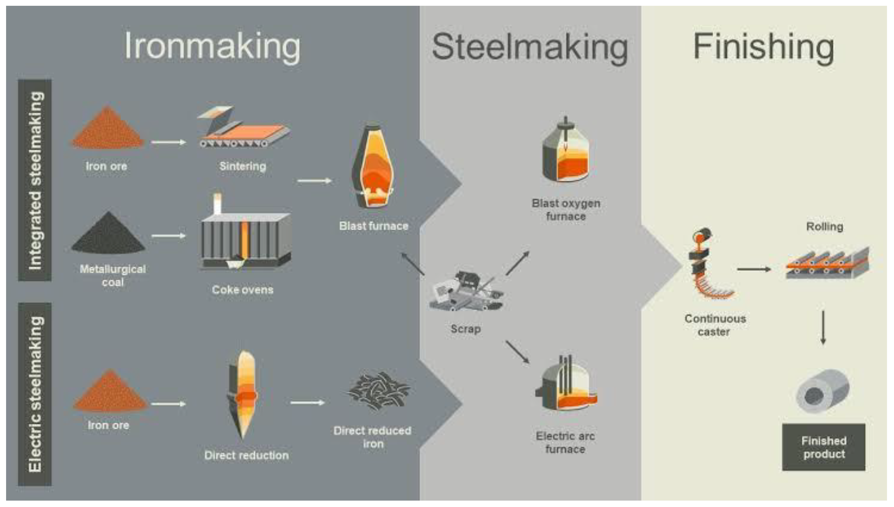
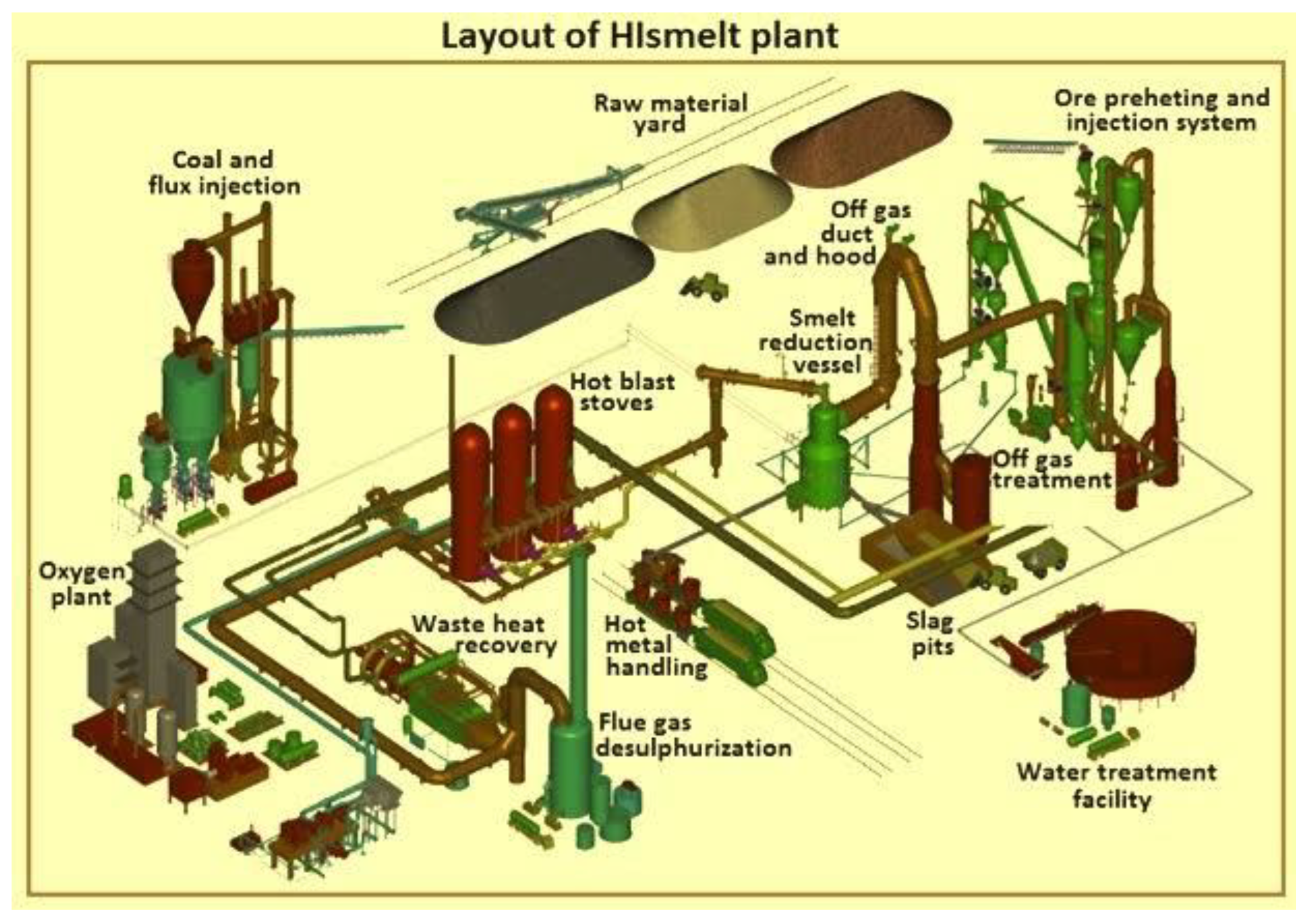
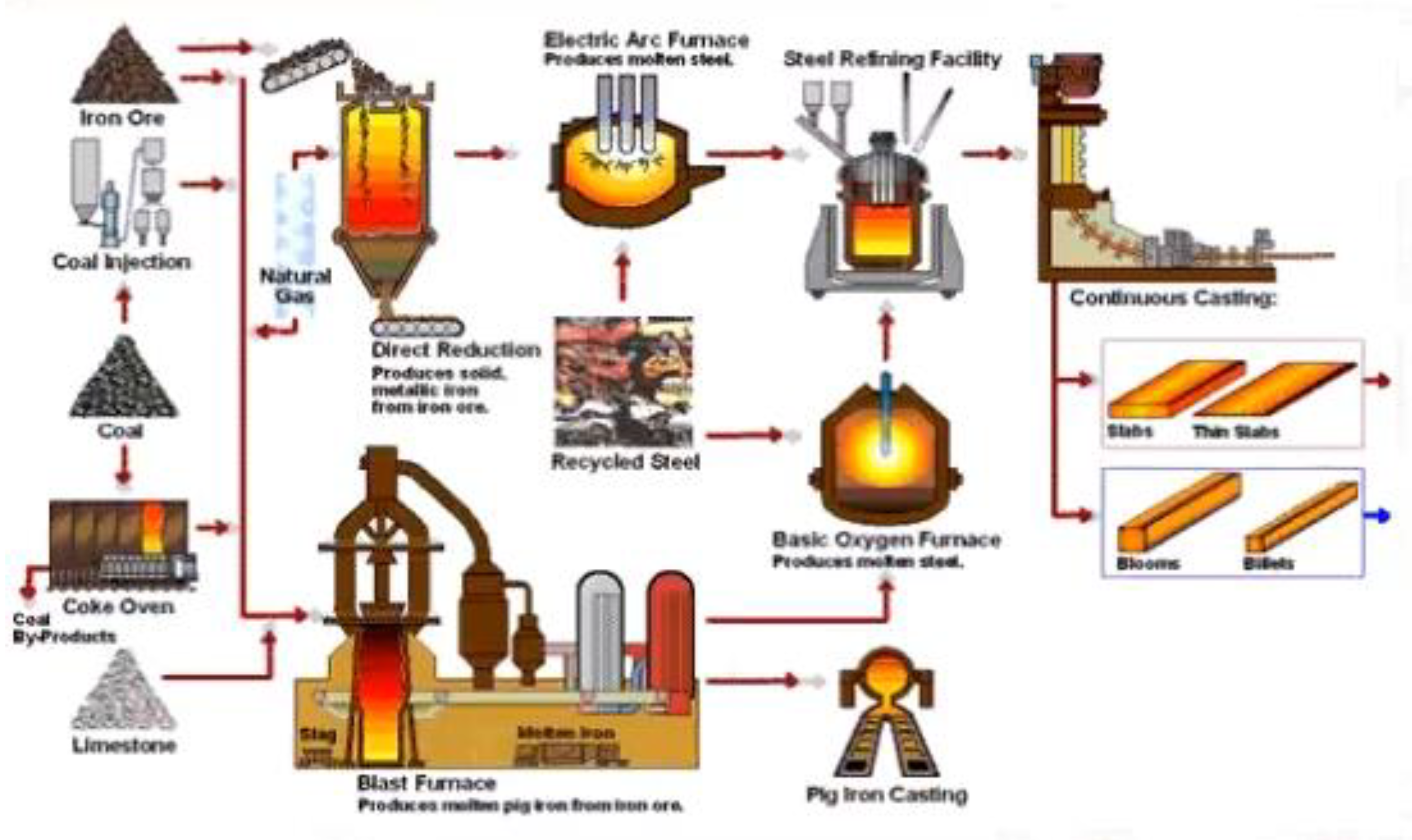
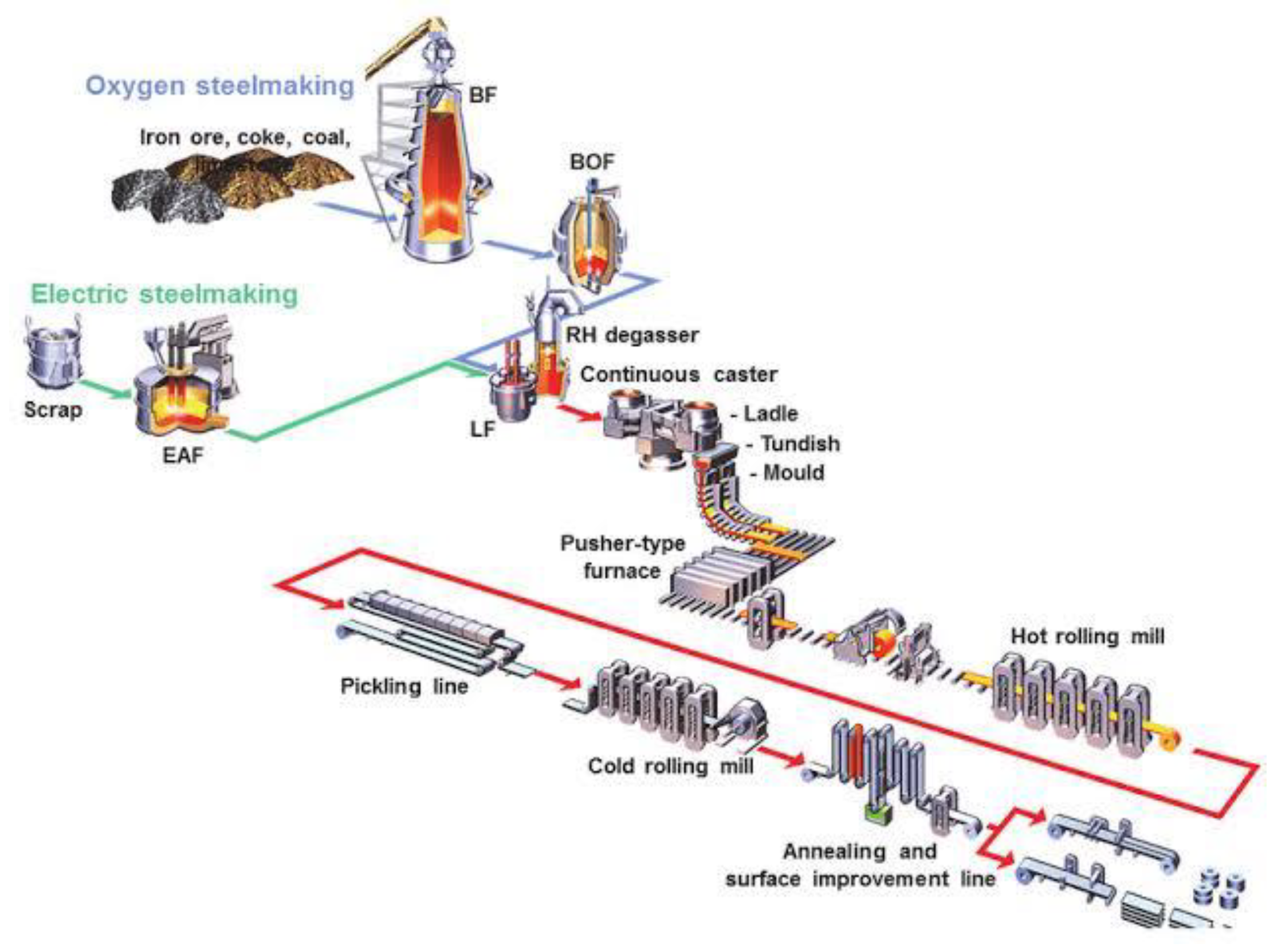
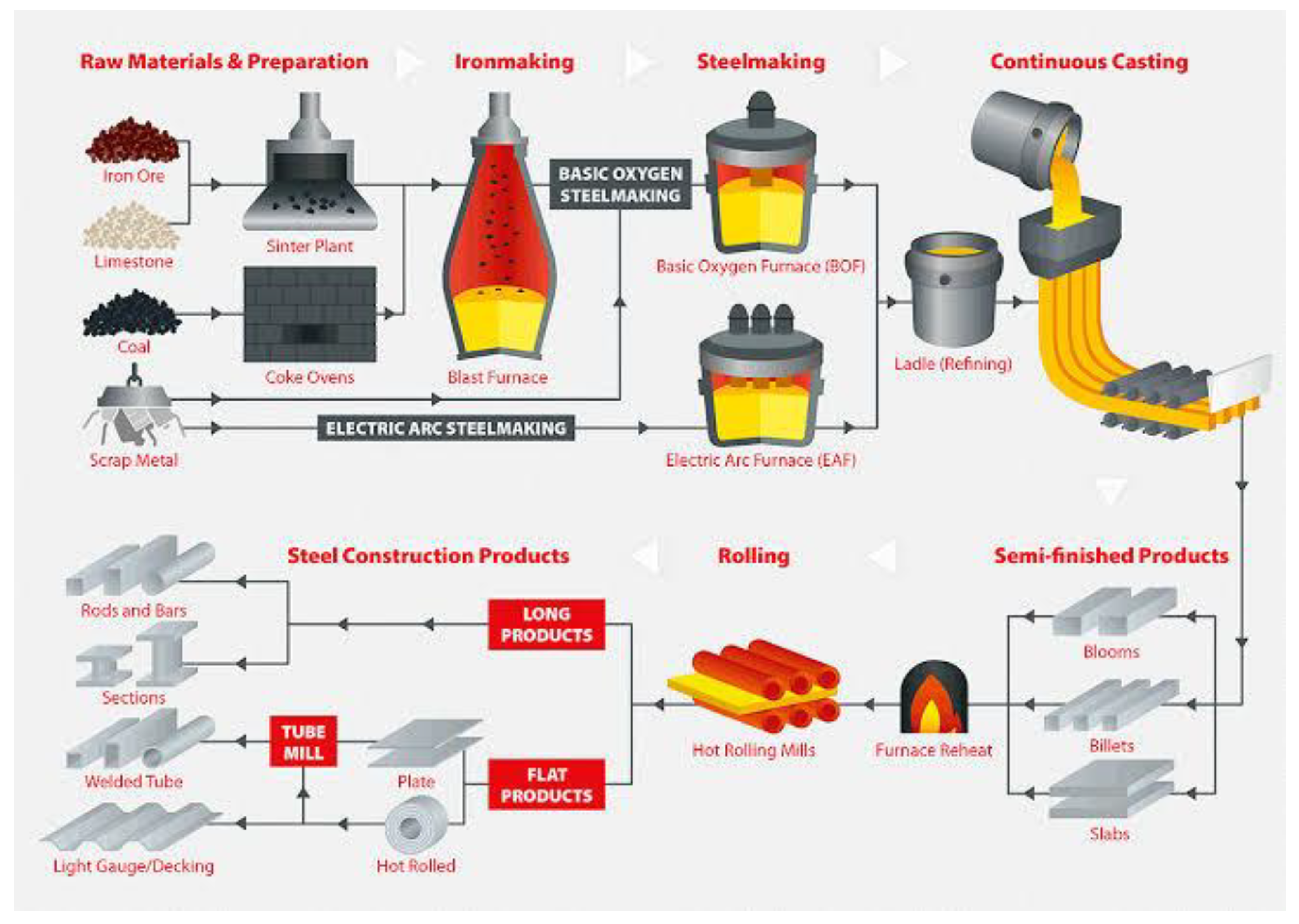
Highlighting the interplay of various stages such as raw material preparation, blast furnace operations, steel production, refining, and casting. This visual representation illuminates the significance of Computational Fluid Dynamics (CFD) in revolutionizing these processes, as it offers a game-changing approach to optimizing parameters like temperature distribution, flow patterns, and chemical reactions. By harnessing the capabilities of CFD, manufacturers can achieve substantial advancements in production efficiency, resource utilization, and product quality, ushering in a new era of innovation and sustainability in the metal, steel, and iron manufacturing industry.
Figure 1, which illustrates the pivotal and intricate nature of iron and steelmaking processes, highlighting the interplay of various stages such as raw material preparation, blast furnace operations, steel production, refining, and casting. The description is accompanied by references from the first five citations:
Figure 1: Pivotal and Intricate Nature of Iron and Steelmaking Processes. Iron and steelmaking processes are complex and involve multiple interconnected stages, as depicted in
Figure 1. The first stage is raw material preparation, where iron ore, coke, and fluxes are processed and prepared for subsequent operations. The blast furnace is a crucial component of this stage, serving as the primary reactor for iron production. Jones and Davis (2022) emphasize the importance of blast furnace operations and highlight the role of CFD in optimizing iron production. They discuss how CFD simulations provide valuable insights into the flow patterns, temperature distribution, and chemical reactions occurring within the blast furnace. The second stage depicted in
Figure 1 is steel production, which involves the conversion of iron into steel through processes like basic oxygen furnace (BOF) or electric arc furnace (EAF). In the BOF process, CFD simulations have been employed to optimize the oxygen injection and mixing, as well as to investigate the impact of lance design on steelmaking efficiency (Thompson and Lewis, 2018). Refining, the next stage, focuses on improving the quality and composition of the steel. Davis and Harris (2021) highlight the use of CFD simulations in refining processes, such as secondary steelmaking, where the flow behavior and heat transfer phenomena during ladle stirring are analyzed and optimized. The final stage depicted in
Figure 1 is casting, where the molten steel is solidified into the desired shapes. Wilson and Walker (2019) explore CFD modeling and simulation techniques for optimizing metal casting processes, including the design of cooling channels and the prediction of solidification patterns. By incorporating CFD simulations at various stages of iron and steelmaking, researchers and engineers can gain valuable insights into the fluid flow, heat transfer, and chemical reactions, allowing for the optimization of process parameters and the improvement of production efficiency.
Researchers from all over the world have used CFD modeling to better understand each of the above iron and steel sub-divisions. These processes can be modeled using highly permeable media, gas–solid reactions, multi-phase flows, and the solution of turbulent Navier–Stokes, heat and mass transfer equations. Part 1 reviews the use of CFD modelling of blast furnaces and better or more efficient processes.
1.2. Blast Furnace
The blast furnace is a crucial component of iron and steelmaking processes, serving as the primary reactor for iron production. It is a tall, cylindrical structure made of steel and lined with refractory materials to withstand high temperatures. The main function of the blast furnace is to reduce iron ore (typically hematite or magnetite) into molten iron using a combination of coke as a reducing agent and hot air injected through tuyeres.The operation of a blast furnace involves several stages and complex phenomena. As depicted in
Figure 1, raw materials such as iron ore, coke, and fluxes are charged into the furnace from the top. The coke acts as a fuel and provides the necessary heat for the reduction reactions. The fluxes, usually limestone or dolomite, are added to promote the formation of slag by combining with impurities present in the iron ore.
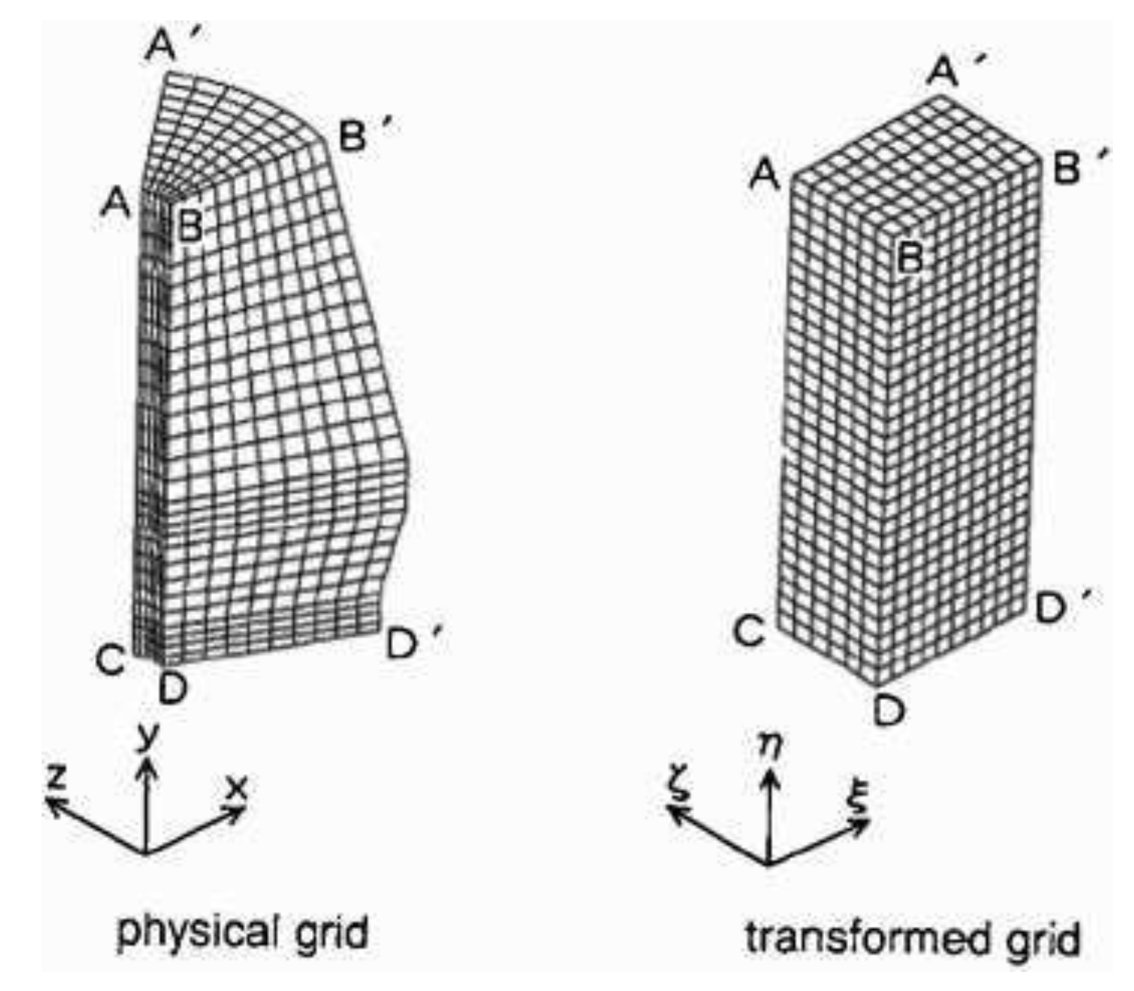
This visual depiction elucidates the intricate arrangement of cells, nodes, and vertices that form the grid, enabling accurate modeling and analysis of fluid flow, heat transfer, and other complex phenomena. The grid system depicted in
Figure 2 represents a crucial element in optimizing manufacturing processes, as it empowers engineers and researchers to effectively capture fine details and variations, leading to enhanced predictions, insights, and ultimately, informed decision-making for improved efficiency and productivity.Inside the blast furnace, a series of chemical reactions occur. As the materials descend, they are exposed to a counter-current flow of hot air injected through tuyeres located near the bottom. The coke reacts with the oxygen from the air to produce carbon monoxide, which acts as the reducing agent for iron ore. This reduction reaction takes place in the upper region of the furnace, where the temperature exceeds 1200°C..The reduced iron, known as hot metal or pig iron, accumulates at the bottom of the furnace due to its higher density compared to the slag. The slag, consisting of impurities and fluxes, floats on top of the molten iron and acts as a protective layer, preventing the oxidation of iron and facilitating the removal of impurities..Jones, A. R., & Davis, P. B. (2022). Advancements in computational fluid dynamics for optimizing iron production in blast furnaces.,analyzed Optimizing blast furnace operations is essential to improve efficiency and reduce environmental impacts. Computational fluid dynamics (CFD) simulations have played a significant role in understanding and optimizing these processes. CFD models can capture the complex fluid flow, heat transfer, and chemical reactions occurring inside the blast furnace, providing insights into phenomena such as gas and solid flow patterns, temperature distribution, and the behavior of slag and metal phase.By employing CFD simulations, researchers and engineers can explore various strategies to enhance blast furnace performance. This includes optimizing the design of tuyeres and gas injection systems, studying the impact of different operating conditions on production efficiency, and investigating methods t reduce energy consumption and emissions.
For many years, scientists have examined the movement of hot metal and heat transmission in a hearth. Most studies employed an uncoupled strategy, with few studies using a coupled approach.27–32 33–35 Also, the non-packed zone of coke created over the dead-man in a fireplace (free space) has gotten little attention. Similarly, data from blast furnace dissection investigations were few.Researchers at Shibata et al.36 looked examined deadman coke and hot metal flow in a blast furnace. A hearth’s flow of molten iron and heat transmission are studied using the general-purpose 3D heat and mass transmission programme ‘STREAM’. This code uses the governing equations, the equation of motion, and the equation for energy/heat transmission:
Momentum equation
Energy
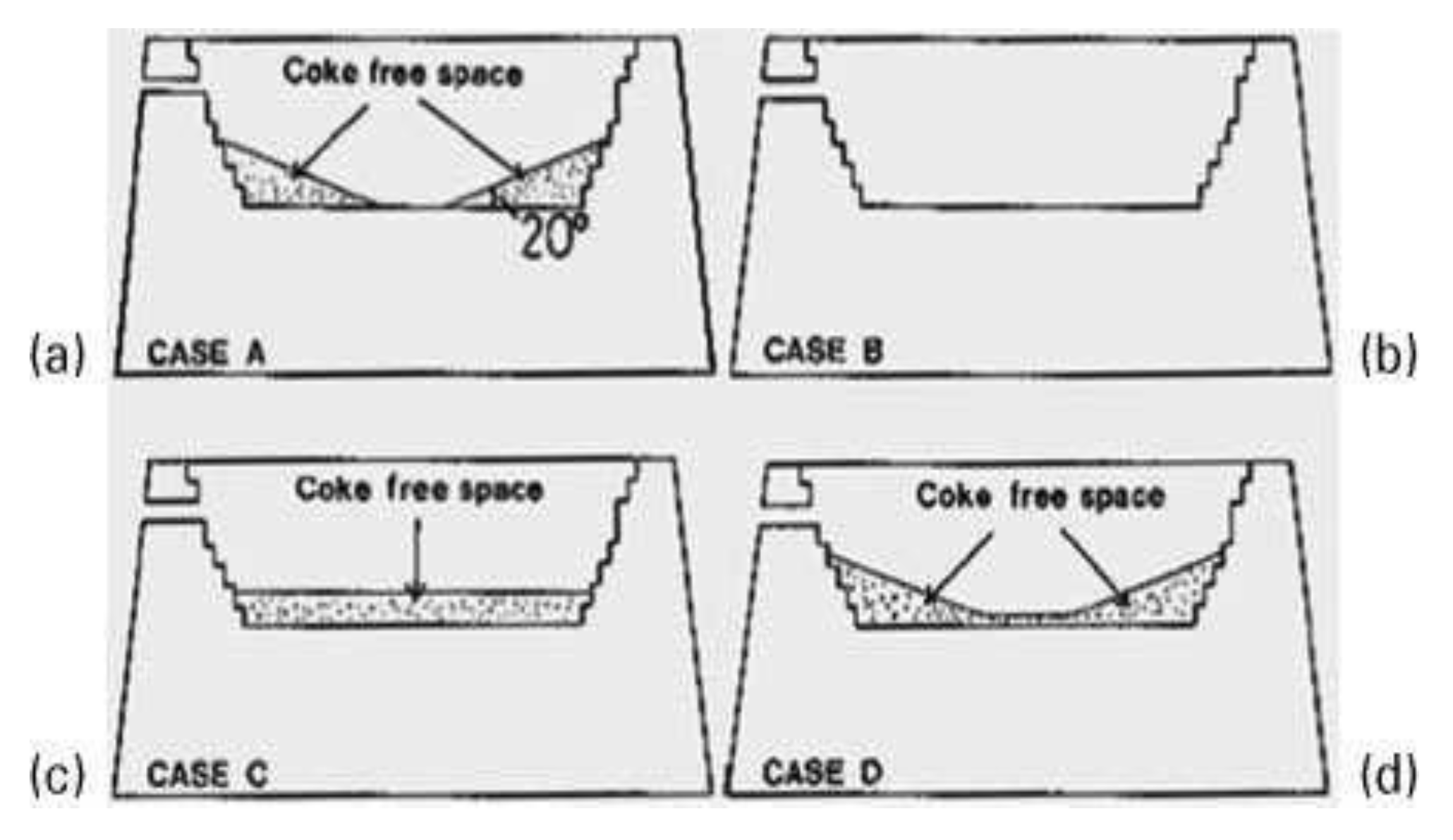
They determined that when molten iron storage levels increase, packed coke particles move towards the raceways. This action creates a coke-free zone (
Figure 3) with a distinct gradient in the hearth’s bottom corner. The gradient changes from 0u to vertical for molten iron storage and drainage. Shape of empty space impacts molten iron flow and heat transmission in hearth. They also highlighted that when the ‘deadman’ void percentage decreases, the circumferential flow of molten iron increases. Proper liquid penetration in a deadman is required to control circumferential flows and avoid hearth erosion.
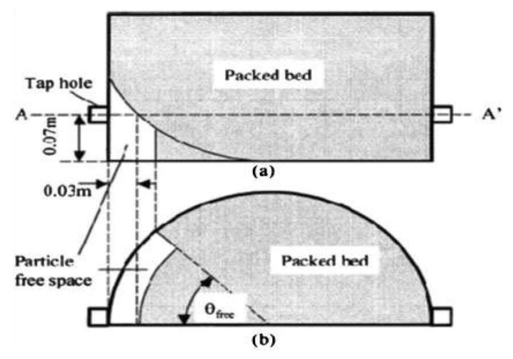
This visual representation offers valuable insights into the spatial arrangement and structural characteristics of the free space, shedding light on its dimensions, boundaries, and potential interactions with surrounding elements. By examining the intricate details captured in
Figure 4, engineers and researchers can gain a deeper understanding of the dynamics within the free space, leading to informed design decisions, improved safety measures, and enhanced overall efficiency in the manufacturing process.
Figure 4 offers a detailed visualization of a free space, providing essential insights into its structure and components. The front view showcases the overall layout and arrangement of different elements, while the horizontal sectional view at the A-A9 plane provides a cross-sectional representation, revealing internal details and spatial relationships.Jones and Davis (2022) discuss advancements in computational fluid dynamics (CFD) for optimizing iron production in blast furnaces. By integrating CFD simulations into the analysis of
Figure 4, we can gain a deeper understanding of the fluid flow patterns, temperature distribution, and chemical reactions occurring within the free space. This analysis can help identify potential areas for process optimization and efficiency improvement.
The flow of molten iron and slag in a blast furnace hearth was modeled in two and three dimensions using the finite difference technique. For the 3D mathematical model, a pressure drop assessment model for a tap hole was built. The 2D mathematical model findings were confirmed using experimentally observed interface shapes. Data from Chiba no. 6 blast furnace were used to confirm the 3D mathematical model’s conclusions. The findings showed that the hearth conditions influenced drainage behavior and retained iron and slag volumes39,40. These factors influence overall drainage rate. Controlling the tap hole diameter change during the tap reduces residual slag volume. A fall in mean coke.
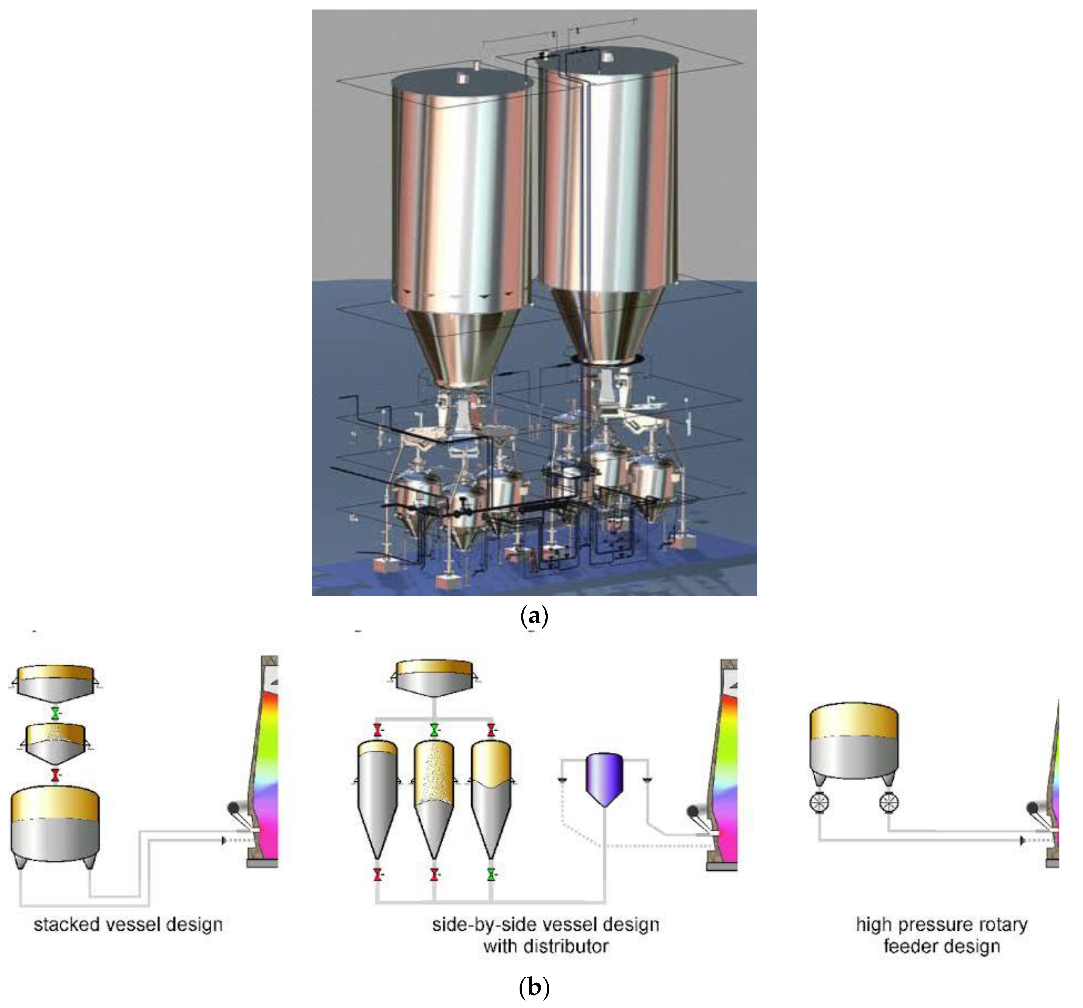
This visual depiction offers a comprehensive overview of the intricate arrangement of equipment, pipes, and injection points involved in the PCI system. By illustrating the flow of pulverized coal and its injection into the blast furnace,
Figure 5a provides invaluable insights into the optimization of combustion, heat transfer, and reduction reactions, enabling manufacturers to enhance energy efficiency, reduce carbon emissions, and improve the overall performance of the ironmaking process.
The diagram depicting a blast furnace equipped with Pulverized Coal Injection (PCI) technology provides a detailed illustration of how the PCI system is integrated within the overall furnace structure, showcasing different designs for implementing PCI in the ironmaking process.
1. Stacked Vessel Design: The stacked vessel design likely represents a configuration where the PCI system is vertically integrated into the blast furnace structure. This design allows for efficient delivery of pulverized coal into the furnace, enhancing the combustion process and reducing the reliance on traditional coke as a fuel source.
2. Side-by-Side Vessel Design with Distributor: The side-by-side vessel design with a distributor showcases an alternative approach to implementing PCI technology in the blast furnace. In this configuration, multiple vessels or injection points are positioned alongside the furnace, allowing for distributed injection of pulverized coal into the hot metal production process. This design may offer enhanced flexibility and control over the injection process, optimizing the combustion of coal and improving overall furnace performance.
3. High-Pressure Rotary Feeder Design: The high-pressure rotary feeder design likely refers to the equipment used to deliver pulverized coal from the injection system into the blast furnace at high pressure. This design ensures a steady and controlled flow of coal particles into the furnace, promoting efficient mixing with the hot blast air and enhancing the reduction of iron ore. By incorporating PCI technology into blast furnace operations, steelmakers can achieve several benefits, including reduced coke consumption, lower carbon emissions, and improved energy efficiency. The integration of PCI systems with blast furnaces represents a strategic approach to enhancing the sustainability and competitiveness of iron and steel production processes. Overall, the detailed representation of a blast furnace equipped with Pulverized Coal Injection technology in
Figure 5b highlights the innovative solutions and engineering designs that drive advancements in modern ironmaking technologies. The integration of PCI technology within blast furnace structures demonstrates a commitment to environmental stewardship, resource efficiency, and process optimization in the steel industry..
This mathematical model can handle molten iron flow, heat transmission, and hearth brick/refractory erosion. To verify the mathematical model, final hearth erosion profiles were compared to deconstructed blast furnace findings. The computed findings matched the measured values well. Using this mathematical model, the impacts of dripping molten iron flow-rate distribution profile, coke free layer size, molten iron production rate, carbon brick thermal conductivity, and fluid flow opposition through the coke fluidized bed reactor were all studied. Using the model and computer code, maximum hearth wear was projected for two distinct designs of operational blast furnaces. Depending on the temperature distribution, the thermal characteristics of refractory materials were replaced by those of hot metal mixed with coke.. The model relied on simplifying assumptions about iron and slag entrance and outflow rates, as well as a notion about how liquid drainage works. Earlier research has shown that these assumptions accurately describe hearth behavior in industrial blast furnaces. The model might be used to simulate how hearth shape, sump depth, production rate, slag ratio, and tapping duration affect the drainage operation.These researchers built a model to simulate and investigate the impact of changing tuyere characteristics and boundary conditions. These included total blast volume, total blast pressure, tuyere diameter, and reductant combustion degree in the tuyeres. An online version of the model was created to monitor changes in tuyere conditions in running blast furnaces. The model anticipated the blast distribution and other important characteristics as tuyere gas velocity, raceway gas volume, and flame temperature.. Modeling multi-phase flow in blast furnaces fell into two groups. One is a macroscopic continuum method and the other is a microscopic discrete element technique. In the continuum approach, phases are seen as completely interpenetrating continuous media, each with its own conservation equation and interaction factors. The continuous technique is ideal for process modelling and practical research. This is how most blast furnace models work. Its efficient utilization is dependent on constitutive or closure relations and phase momentum exchange. For Newtonian fluids (gas and liquid), these relationships are clear. No universal theories exist for non-Newtonian fluids like solids and powders. It describes phases by analyzing the motion of specific fluid constituents, such as atoms in gas or liquid, or particles in solids. So, the method can replicate atomic and particle size fluid flow. It avoids intricate constitutive interactions between stress and strain tensors under various flow circumstances. It may create tiny data such as atom or particle trajectory and forces, which is vital to comprehending basics. However, it is computationally intensive. As a result, no realistic system can have gas or liquid phases. The aforementioned continuum phase technique is superior for them. It has only been used on solid phases thus far. For process design and control, they found that blast furnace models have been useful in integrating knowledge. The fast advancement of computer technology and new modeling approaches will bolster this position. They said that the use of credible computer models may lead to longer campaign life, better operational control, less fuel consumption, increased productivity, and reduced environmental impact. Modern iron producers may struggle to make the most use of this technology in reality.To save money and reduce emissions, pulverized coal is injected directly into an iron-making blast furnace. There are significant economic motivations to reduce coking coal use and hence extend coke oven life, and to increase blast furnace output. A mathematical method, notably CFD, is a cost-effective technique for studying coal combustion. PCI includes turbulent gas–solid two-phase flow, momentum/mass/heat transfer, and numerous homogeneous and heterogeneous chemical processes. In the 1980s, 1D mathematical models for PCI were established. By the 1990s, 2D models became standard. Nevertheless, a 2D model can only provide qualitative results. 3D models are required to overcome this. complicated transport phenomena occur inside a blast furnace, and CFD has played a vital role in understanding and improving the process during the past three decades.
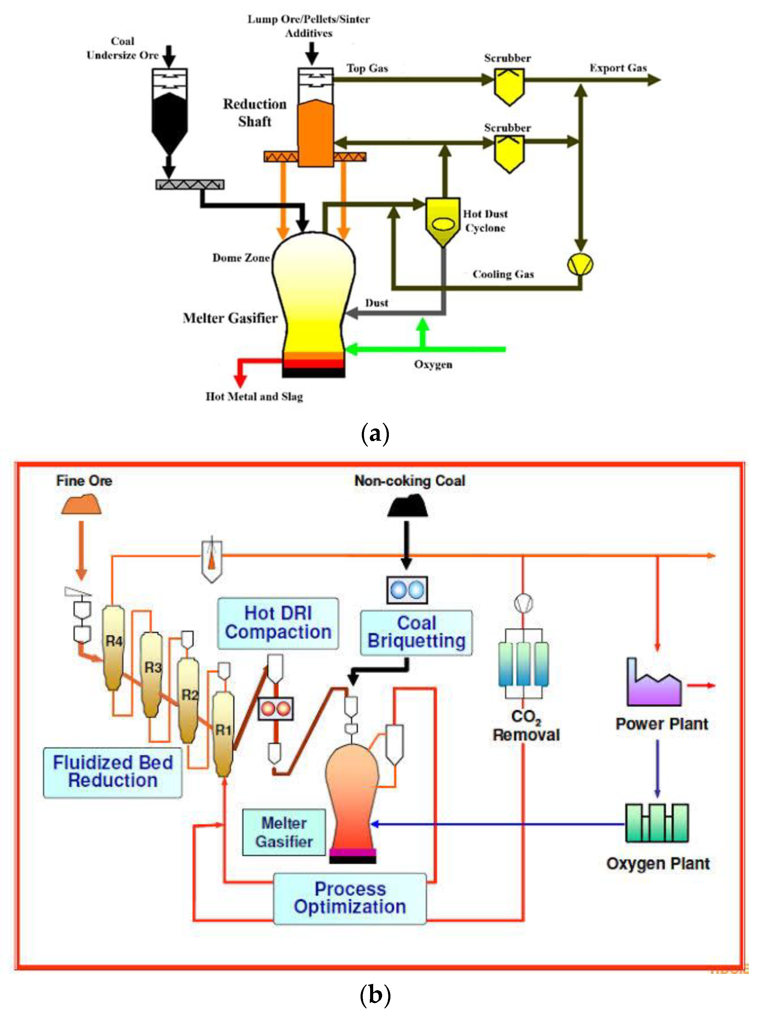
The diagram depicting the Corex process provides a detailed and insightful overview of the key components and operational stages involved in this innovative ironmaking technology. Each component plays a crucial role in the overall process, contributing to the efficient production of hot metal and slag. 1. Coal: The use of coal in the Corex process serves as a reductant, providing the necessary carbon for the reduction of iron ore. 2. Undersized Ore: Undersized ore refers to finely crushed iron ore that is fed into the reduction shaft for processing. 3. Reduction Shaft: The reduction shaft is where the iron ore undergoes reduction through the reaction with coal to produce hot metal. 4. Top Gas Scrubber: The top gas scrubber helps remove impurities from the gas produced during the reduction process, ensuring a cleaner and more efficient operation. 5. Dome Zone: The dome zone likely plays a role in the containment and regulation of gases and materials within the Corex system. 6. Melter Gasifier: The melter gasifier is where the reduction reactions take place, converting iron ore into hot metal and slag. 7. Hot Metal And Slag: The hot metal and slag produced in the process are essential outputs that can be further processed for use in steelmaking. 8. Dust: Dust is a byproduct of the Corex process that needs to be managed and controlled to maintain a clean working environment. 9. Cooling Gas: Cooling gas is used to regulate temperatures within the system and aid in the cooling of hot metal and slag. 10. Hot Dust Cyclone: The hot dust cyclone likely serves to separate dust particles from the gas stream for environmental and efficiency purposes. 11. Export Gas: Export gas could refer to the gas that is not used within the system and may be utilized for other purposes or released into the environment. 12. Lump Ore/Pellets/Sinter/Additives: These materials are essential inputs that are fed into the Corex process to facilitate the reduction reactions and production of hot metal. Overall, the diagram provides a comprehensive visual representation of the Corex process, highlighting the various stages and components involved in this advanced ironmaking technology. Each component plays a unique role in driving the efficiency and effectiveness of the process, ultimately leading to the production of high-quality hot metal and slag.
The diagram illustrating the integration of the Corex and Finex processes represents a significant advancement in the ironmaking industry, combining the strengths of both technologies to revolutionize iron production. The integration of these processes allows for enhanced efficiency, flexibility, and sustainability in the production of direct reduced iron. 1. Fine Ore: Fine ore serves as the raw material input for the integrated Corex and Finex processes, providing the iron source for reduction. 2. R1, R2, R3, R4: These components represent different reactor stages within the integrated process, each playing a specific role in the reduction and transformation of iron ore into direct reduced iron. 3. Fluidized Bed Reduction: The fluidized bed reduction stage is a key component where the fine ore undergoes reduction using a fluidized bed reactor, facilitating efficient and controlled reactions. 4. Melter Gasifier: The melter gasifier is where the reduced iron is further processed to produce hot direct reduced iron (DRI) and slag. 5. Process Optimization: Process optimization is crucial for maximizing efficiency and productivity in the integrated Corex and Finex processes, ensuring optimal performance at each stage of iron production. 6. Oxygen Plant: The oxygen plant likely provides the necessary oxygen for the reduction reactions and process control within the integrated system. 7. Hot DRI Compaction: Hot DRI compaction refers to the process of compacting the direct reduced iron into dense, easily transportable forms for further processing. 8. CO2 Removal: CO2 removal is a critical step in reducing greenhouse gas emissions and improving the environmental sustainability of the ironmaking process. 9. Non-Coking Coal: The use of non-coking coal as a reductant in the integrated process demonstrates a more sustainable approach to ironmaking, reducing reliance on traditional coking coal. 10. Power Plant: The power plant provides the energy required to operate the integrated Corex and Finex processes, ensuring a reliable source of electricity for the operation. The integration of the Corex and Finex processes through this comprehensive diagram showcases a holistic approach to ironmaking that emphasizes efficiency, sustainability, and innovation. By combining the unique features of each process, manufacturers can achieve higher productivity, lower environmental impact, and greater competitiveness in the iron production industry


