Preprint
Article
Spectral Properties of Bistatic Radar Signals using the Ray Tracing Technique and a Facet Approach
Altmetrics
Downloads
433
Views
38
Comments
0
A peer-reviewed article of this preprint also exists.
This version is not peer-reviewed
Submitted:
20 May 2024
Posted:
21 May 2024
You are already at the latest version
Alerts
Abstract
Bistatic radar experiments have been used to study surface characteristics of extra-terrestrial bodies in the Solar System, including the Moon, Venus, Mars, and Titan. This paper proposes a 3D model to characterize the scattered field of a Gaussian rough surface on an extra-terrestrial body for an orbital bistatic radar configuration. Specifically, this model will investigate how the variability of surface roughness impacts the spectral broadening of the received signal using physical optics approximations and ray tracing on a surface model using a facet approach with Gaussian properties. A linear relationship between spectral broadening of the signal and surface roughness was found. This relationship is in line with results obtained by commonly used analytical models for bistatic radar on planetary surfaces.
Keywords:
Subject: Physical Sciences - Space Science
1. Introduction
Remote sensing using bistatic radar configurations, where the transmitter and receiver are spatially separated, uses scattering off a surface to measure surface characteristics such as roughness, reflectivity, and dielectric constants. Bistatic radar for the study of statistical surface characteristics was first applied to the lunar surface [1] in the 1960s where the spacecraft (S/C) and a terrestrial ground station served as the radar transmitter and receiver, respectively. In addition to the moon, bistatic radar on space missions has been used to study the surfaces of extra-terrestrial bodies in the Solar System [2,3,4]. Bistatic radar used to study planetary surfaces includes not only orbital-Earth configurations but also the use of multiple terrestrial ground stations. Terrestrial bistatic radar observations have provided crucial information for space mission planning [5]. Additionally, a bistatic configuration between a lander and a spacecraft has been used to provide surface roughness data by the Huygens lander on Titan for the NASA/ASI/ESA Cassini-Huygens mission [6] and by the Philea lander on comet 67P/Churyumov-Gerasimenko (67P/C-G) for the ESA Rosetta mission [7].
The relationship between the characteristics of the received radar signal and the statistics of a rough surface, such as the root-mean-square (rms) slope, is used to constrain the roughness of the surface at scales of the incident wavelength (cm). Polarization of the bistatic forward scattering can be used to determine the dielectric constant of the surfaces as well detect the presence of water-ice on lunar and planetary surfaces using same sense circular polarization of the signal. The roughness of geological surfaces at microwave wavelengths is important to planetary geology and enables identification of geological unit types, geomorphological changes over time, geophysical processes, and the presence of volatiles on the Moon [8,9], Venus [10,11], Mars [12,13,14], Titan [15,16], Pluto [17], asteroid Vesta [18] and comet 67P/C-G [19,20] among others. Characterizing surface roughness also provides crucial data for planning space missions that include landers and rovers as well as surface sampling. Future missions such as ESA’s Jupiter Icy Moons Explorer (JUICE) will utilize bistatic radar to study the surface properties on Ganymede [21]. In addition, future bistatic experiments could include micro satellite networks instead of a S/C in an orbital bistatic configuration as well as a possible unmanned aerial vehicle (UAV) to rover configuration like the Mars Helicopter demonstration (Ingenuity) currently being tested with the Perseverance rover on Mars [22,23,24,25].
Typically, bistatic radar data uses a downlink configuration between the S/C and Earth, where the transmitter is on-board the S/C as part of the telecommunications system and the terrestrial ground station is the receiver. However, for the New Horizon mission to Pluto, an uplink configuration, where the receiver is on-board the S/C and the terrestrial ground station transmits commands after the scattered signal is received, provided the necessary higher signal-to-noise ratio given the extreme distance involved as well as the high speed of the S/C during its flyby at Pluto [26].
2. Background and Goals
Orbital bistatic radar experiments transmit continuous sinusoidal signals from the S/C moving with a certain velocity with respect to the surface at a particular incident angle. As a first approximation, the surface of a planet, which at microwave wavelengths can be assumed to behave as a gently undulating surface, is considered to scatter the transmitted radar signal primarily in a specular manner [2]. The angle of incidence equals the angle of reflection, as shown in Figure 1 assuming the azimuthal angle between the plane of incidence and observation is zero. The surface is broken down into various planar scattering elements, each tangential to the existing surface, and the received signal is considered to be a summation of specular reflections from individual scattering elements or facets that are oriented to receive the direct energy of the transmitted signal. This model produces quasi-specular scattering due to randomly oriented perfectly flat facets. Diffuse scattering due to wavelength-scale surface features and sub-surface scattering can be part of the total scattering from a planetary surface, but are neglected in this analysis. The quasi-specular model is based on the Kirchhoff or tangent-plane approximation and the stationary phase or high-frequency approximation to describe the surface (e.g., [27,28]). Kirchhoff’s approximation assumes that the spatial scale of the surface structure is larger than the incident wavelength and the high-frequency approximation assumes that only those surface facets whose slope enables a specular reflection of the transmitted ray contribute to the radar cross-section. The size of the surface facet should approximate at least one wavelength, thus reducing diffraction effects, while the dimension of the effective Fresnel zone is the upper limit [29,30,31]. In this case, where the electromagnetic wavelength is much smaller than the surface radii of curvature, geometrical optics approximations are valid.
The typical incidence angles for planetary bistatic orbital configurations have ranged between 40 and 70 degrees. While analytical models relying on quasi-specular scattering are not considered reliable for high and low (grazing) incidence angles [32,33] due to shadowing, diffraction, and multiple scattering effects, in Ref [34] Gunnarsdottir found data produced in multiple high incidence angle bistatic radar experiments for Mars in good agreement with MOLA data from the Mars Odyssey mission.
The power of the received signal emitted from the surface facet reflects the characteristics of the transmitter and receiver antennas and of the surface facets as shown in Equation (1)
where dPR is the incremental received signal power, PT is the transmitted power, GT is the gain of the transmitter antenna, AR is the effective area of the receiver antenna, while RT and RR are the distances to and from the surface facet from the transmitter and the receiver, respectively. Finally, σ is the bistatic radar cross section (RCS) of the individual surface facet and is written as:
and is a function of the slope or tilt angle of each element. The slope indicates how closely the facet aligns with the case of specular reflection. The smaller the slope, the more closely the facet aligns to specular reflection and the greater its effect on the received signal.
Scattering laws based on Gaussian and exponential forms have been used to investigate scattering off a quasi-specular surface. However, the most commonly accepted scattering law for the bistatic RCS is Hagfor’s law which is based on a Gaussian height distribution and an exponential autocorrelation function for surface length and frequency components. Hagfor’s law is also used with other surface models, such as fractal surfaces, where it is considered a special case, along with Gaussian and exponential scattering laws, in fractal-based scattering laws [35].
The S/C produces a radar swath of data as it moves across the surface and causes the received signal to be spectrally broadened due to variations in the Doppler shift at different points within the footprint and along the surface track. The surface facets, which are also moving with a planetary velocity, produce a bistatic Doppler shift relative to the transmitter and receiver. The degree to which the received signal is spectrally broadened is proportional to the surface roughness:
where B is the half-power bandwidth of the received signal, V is the velocity of the specular point across the surface, ζ is the rms surface roughness and φ is the incidence angle [1]. Thus, a wider received signal bandwidth is a result of a rougher surface and/or a higher velocity S/C. However, if the surface becomes too rough, some of the facet scattering will be outside of the illumination pattern of the transmitting antenna thus reducing the power of the received signal (beam-limitation).
In this paper, we investigate how the variability of surface roughness affects the spectral broadening of the received radar signal using a quasi-specular model with both a physical optics approach and a geometrical optics approach by means of ray-tracing. The surface is modeled as a collection of local facets with Gaussian surface statistics and includes both isotropic and anisotropic surfaces. While numerical methods such as the Integral Equations Model (IEM) and the Methods of Moments (MoM) can solve Maxwell’s equations numerically and provide an exact solution, they are computationally expensive. Ray-tracing provides an approximate solution to Maxwell’s equations in the high-frequency regime. Physical optics is used to generate the surface model and to obtain Doppler shifts and subsequent changes to the received signal bandwidth. We will also investigate the effect of minimum ray density on the results of this model.
This numerical model has been developed using the MATLAB interface for SPICE (Spacecraft, Planet, Instrument, “C-matrix”, Events) open access code developed by NASA’s NAIF (Navigation and Ancillary Information Facility). The numerical model can be seen as consisting of three basic steps; model parameter generation, ray propagation and signal analysis. Model generation includes the generation of basic parameters necessary to determine the received signal characteristics such as positions of the transmitting and receiving antenna (satellite and terrestrial ground station) and planetary target, antenna footprint coverage, beam angle as well as generation of the rough faceted Gaussian surface. This data can be self-generated or else pulled from SPICE mission databases. Electromagnetic wave propagation in this model between the satellite, planetary surface and receiving antenna will be approximated by ray-tracing technique. After this, the Doppler shift of the signal and the signal bandwidth can be calculated so that the relationship between the surface roughness and the spectral broadening can be ascertained.
3. Surface Properties from Quasi-Specular Radar Backscatter
We present the model used to generate the scattered field from a rough surface illuminated by a transmitting antenna simulating wave propagation using ray tracing algorithms. The discussion will first focus on the ray tracing algorithm used to determine the position of the reflected ray on a smooth surface and then a rough Gaussian surface. To determine the direction of the reflected ray, the rough surface will be decomposed into triangular micro facets. The receipt of the signals will be determined using both circular region-based, and angle-based receiving conditions. Finally, the characteristics of the signal will be examined. The parameters used in this model are presented in Table 1. The positions of the components of this model (satellite transmitting antenna, planetary surface, and receiving antenna) can be self-determined or else downloaded from the SPICE libraries for a specific space mission. The planetary surface considered here is a perfectly conducting spherical one with a Gaussian height distribution.
Using Kirchhoff’s and the high-frequency assumptions, we assume the local points on the planetary surface to be a tangent plane approximation to the actual surface and we assume the roughness is smaller than the wavelength thus the scattering of the local surface is equivalent to the specular reflection of a smooth surface. In this case, the direction of the reflected wave will obey Huygens’ principle such that the incident and reflected (in this case scattered) angle and points are equal and the incident ray, reflected ray, and surface normal all lie in the same plane as seen in Figure 1. The magnitude of the reflected ray can be determined using Fresnel’s reflection coefficients. For this model, we will assume all the Fresnel reflection coefficients are unity. Thus, to determine the reflected ray, the incident direction, the incident surface location, and the normal to the surface at the interception point are necessary. As shown in Figure 2, the position of the satellite at an epoch time , is designated as , the position of the receiver antenna at epoch time is , and is the centre position of the planetary surface. The position of the central ray intercepting the surface at epoch time is , which can be obtained by referring to , and or else by using the SPICE software functions.
While illuminating the surface with a large number of radio rays would lead to a higher resolution it would also lead to slower ray-tracing computation due to the increased need for ray interception checking. To limit the ray tracing computational time, the model initially sets the number of rays equal to the number of surface elements, , with N being equal to the number of divisions along each side of the half-power beamwidth, which generates a square grid of elements.
3.1. The Simulation of Reflected Signals
To trace the ray through the model, we assume that the satellite transmits a bundle of rays at a certain half-beam angle, α. For the sake of the algorithm, the beam footprint can be assumed to consist of a central curve along with a left and right curve. This algorithm processes the ray interception points along the central curve first and then the lateral points going left to right along the footprint. We use the Law of Reflection which states that the incident ray, reflected ray, and surface normal all exist in the same plane and that the incident angle equals the reflected angle. In short, a point on the central curve exists within a plane defined by that point and the positions of the satellite and planet and this plane has a normal which goes through the point and the center planet position as seen in Figure 2. Thus, the reflected ray position and angle can be found rotating the point around the normal. While in reality the reflected ray position equals the surface interception ray position, for the sake of this algorithm it is defined as another point. This new point, similar to the initial point, is defined as existing within a plane defined by itself and the positions of the satellite and planet with a normal going through itself and the planet’s position. At the local ray interception position, on the central curve, , the reflected ray position and direction can be obtained by the rotation of around the normal to the plane on the central curve determined by the surface interception point, along with and , denoted as . The normalized vector, denoted as , that rotates around, is the normal to this plane, , and goes through point . The range of the rotation angle, , is between , and the rotated by is denoted as , shown in Figure 2; this point represents the reflected/scattered point. This point, similar to the initial ray interception point, , is also defined as existing within a plane defined by the reflected point, along with and . The normal to at is denoted as . The vector from to , denoted as , is perpendicular to the normal at , .
To determine a position laterally offset from the central curve, denoted as , the offset length between the corresponding point on the central curve, , and can be determined using the geometrical relationships between the length of the vector from to , denoted as , which is perpendicular to the normal at , and the angle, , formed between the vectors and as shown in Figure 2. The distance between and , denoted as , can be obtained by
The position of the offset point is thus:
where , is normalized .
Using a ray-tracing algorithm we can determine the position and direction of scattered/reflected rays. However, these reflection points are generated by assuming a smooth surface. In practice, the surface is rough, and each illuminated surface element can be described as having a height profile with a particular root mean square height distribution, denoted here as , and a particular correlation length which determines the spatial frequencies over the surface in the x and y directions, denoted herein as and . In this model, we consider the local illuminated surface to be a square area with a local surface coordinate system . The origin of coordinate system is denoted as . We use the spacecraft as a reference point and maintain that the directions from north to south and from left to right are positive. The characteristics of the system are shown in Figure 3.
Overlaid upon this coordinate system is an auxiliary square grid, with Gaussian elevation associated to the nodes of the grid, used to simulate the rough surface; thus, the number of auxiliary elements in the or direction is , resulting in total elements. The number must conform to the Nyquist theorem in the spatial domain such that the number of auxiliary elements per unit length is inversely related to the correlation length for its lower limit. This relationship also provides constraints for the side length of the square facet (N/SL > 2/CoX).
The element side length visible to the transmitter at a certain time epoch is approximately:
To simplify the description, the generated auxiliary elements overlaid on the coordinate system are numbered as where and are row number and column number respectively. The elevation data of is initialized by .
Figure 4a shows an example of an grid of auxiliary elements. To generate a random matrix with a Gaussian distribution, as seen in Figure 4b, we use MATLAB’s random number generator function .
To produce a spatially correlated surface, this surface is convolved with a Gaussian filter using MATLAB’s discrete Fast Fourier Transform (FFT) function. When , the surface is considered isotropic, meaning the roughness is the same in the and directions and thus scatters light evenly in all directions. To achieve a spatially correlated isotropic surface, the Gaussian filter with a low pass frequency response is
Where and are coordinates of on and respectively. Using this Gaussian filter in addition to the inverse , to change from the spectral domain to the spatial one, we can obtain the rmsH for the facet,
where * is the dot product between two vectors. The spatially correlated surface seen in Figure 4c, is the result of the convolution of H and the Gaussian filter for an isotropic surface. On the other hand, When and are different, the surface is considered anisotropic, meaning the roughness varies in the and directions thus scattering light in different directions with different intensities. To achieve a spatially correlated surface for an anisotropic, the Gaussian filter with a low pass frequency response is
With this auxiliary grid we can correct the initial reflection point by adding the rms height ()
Now that the reflection points on the rough surface elements can be calculated there is the possibility that an overlapping or shadowed area possibly exists between two adjacent illuminated surface elements when the moving step of the spacecraft during the simulation is short. Considering that the elevation data of each illuminated surface is independently generated, it is necessary to correct the elevation data of the latter illuminated surface located in the overlapping part. Supposing the moving step is denoted as , the point belonging to the latter illuminated surface and overlapping part can be denoted as . After projecting the overlapping part on the system, it is easy to find which element belonging to the former illuminated surface that will be located in. Supposing this element is , can be corrected and replaced by the intersection of vector and element .
Once the reflection positions are determined, the direction vector of the reflected ray must be determined. The rough surface is meshed using a collection of non-overlapping triangular facets approximating the surface shape. In this way, the intersection of a ray with each triangular facet is calculated. The points selected to create the surface element are , and , where is selected as the reflection point of this surface element. An arbitrary facet denoted as is seen in Figure 5 projected above the local surface coordinate system.
To determine the normal to the triangular facet plane, , the cross product of two edges is calculated. To find the vector of the reflected ray , the component of the incident ray is reversed parallel to the triangle facet normal such that
where * is the dot product, is the incident ray.
3.2. Modeling the Reception of Reflected Signals
Compared with the reality, the simulation of radio waves in terms of quantity is usually under-estimated. Hence if the receiving condition for reflection signals is strictly set, just several reflected signals can be captured by the receiver and the analysis result will also be underestimated. As shown in Figure 6, a circular receiving range is utilized to define the receiving ability of receiver. This circle is perpendicular to the vector from to , denoted as , and the center of this circle is . However, as has mentioned before, the underestimated quantity of simulated signals will cause negative influence on the analysis result. So, this receiving plane should be put at a nearer position to the explored planet, which can be denoted as . The intersection point of and receiving plane is denoted as . The reflected signal is regarded to be received when meeting that
3.3. The Doppler Shift of the Received Signals
Figure 7 shows the relative spatial positions of transmitter, surface and receiver, as well as several incident and reflected signals, where the sum of and are the total path length of the ray. Assume the transmitting signal is denoted as
Assuming that each reflected signal reaching the receiver have the same field intensity. Hence, the reflected signal reaching receiver can be denoted as
where is the frequency of transmitting signal and . is the velocity of radio wave, with the value of 3 ∗ m/s. Equation 19 can be further expressed by
The equation of signal via element is denoted as
Therefore, the frequency of received signal can be expressed by
In the frequency domain, the received overall signal will show a Gaussian shape because of the Doppler shift. To get the frequency of overall received signals, a simple method is fast Fourier transform (FFT). However, because usually the signal frequency configured for spacecraft is high, and the sampling frequency conducting FFT should be higher than , the performance of FFT will cause unacceptable computation consumption. Considering this drawback, the method employed here is to record the frequency of all the received signals and compute the largest frequency difference. This frequency difference can be approximated to be confidence interval of the Guassian shape and is crucial to obtain the half-power width of the frequency-domain signal.
3.4. The Computation of the Rms Slope
For radar signature analysis, the rms slope rather than the rms height, , is typically used. The rms slope is the derivative of the local surface tilt in the z direction as a function of the length of the local facet. The computation of is conducted on the statistics of all surface elements. As shown in Figure 8, the slope for element , denoted as , can be obtained by
The rms slope of the illuminated surface is then obtained by
4. Numerical Simulation Experiments
To investigate the reliability and numerical stability of BIRDS, in this section we study the influence of the number of incidence waves on the backscattering surface of the planetary body. This is useful to quantify the computational burden of each simulation as a function of the achievable accuracy in the estimation of the surface roughness.
4.1. Case 1: Mars Bistatic Radar Experiments
We start by simulating a BSR experiment scenario at Mars, remembering that a usual problem encountered in the real Mars environment is that, with a typical S/C and orbital design, the beam is limited, and cannot work efficiently on Mars’ high-rough surface. To prevent this problem, in this simulated Mars BSR experiment, the half-beam width of the onboard HGA is fixed to . Moreover, to maximize the number of amount of received signals reflected from the surface, we fixed a receiving mask cone of 10° aperture, which is an unrealistically large value, but this avoids simulating a huge number of RF beams, so to speed up the numerical simulation. We decided to consider, as the only independent parameter, the angular separation between two adjacent incidence waves, which can be denoted as . In our simulation, we varied between 0.155° to 0.075° (with steps of 0.02°), which means the total number of incident waves, simulated in the experiment, varied between 29387 and 160000. For each numerical experiment carried out using a different value of we computed the half-power bandwidth of the total simulated received RF signal (which is the sum of all the individual simulated waves) to compare it to the analytical prediction given by Eq. (3). The left panels of Figure 8 depict this comparison for a variety of different BIRDS-simulated RMS slopes of the illuminated area on the surface of Mars. From the top row to the bottom row the angle is gradually decreased and, while the prediction of Eq. (3) is shown as a solid line, the results obtained from 5 independent runs are given by box plot. The right panels of Figure 8 also show the number of the received waves in the five different values of the angle. For each RMS slope, we show our results as follows: the red horizontal line represents the average value of the received signals (for the same five runs of BIRDS described above), the blue box represents the standard deviation of the same fine runs, and the black dashed lines represent the minimum and maximum limits of the five runs. These plots show that while increasing the number of the received signals (via decreasing the angle) the half-power bandwidth of the received echo from BIRDS gradually approaches the result of Eq. (3) and the vertical bars become smaller, see left panels of Figure 8. In the current range of RMS slope for the illuminated surface, the number of received waves increases as a quadratic function, see right panels of Figure 8, and the panel in the last row (plot (j)) offers the best match to a quadratic function, with the lowest variabilities.
The left panel of Figure 9 depicts the average value of the error between the numerical simulations and the analytical prediction given by Eq. (3) by generating different number of incident signals. It shows that when the number of received waves is larger than 40000, the error can be limited to about 50 Hz. When the number of incident waves is 160000, the error can be limited to about 25 Hz. It indicates that increasing the quantity of incident waves can effectively improve the system’s stability. The standard deviation of the error between the numerical simulations and the analytical prediction given by Eq. (3), for 5 runs of the BIRDS simulator, is also shown in the right panel of Figure 9. This shows that the standard deviation of the error in the half-power bandwidth for a small quantity of incident signals (29387, in particular, in Figure 9) is totally unreliable, as it is remarkably small (even smaller than the average error), an artifact of the few received signals. On the other hand, when the quantity of the received waves reaches 90000, the standard deviation of the error can be limited to about 35 Hz.
In Table 1, the rms slope of the generated surface and the one computed from Eq. (3) are compared. The rms slope computed using Eq. (3) relies on the rms height and irregularity horizontal length. The rms heights (in km) are given in the first column, and the rms slopes computed using the numerical simulations carried out under the different hypothesis of grid points are shown in the second to sixth columns, while the rms slopes computed via Eq. (3) are given in the last column. An interesting phenomenon can be observed is that by referring to the results shown in Figure 8 and in Table 1, the computed bandwidth is relevant to the precision of the reconstructed rms slope. In order to lower the error in the rms slope estimation, the computed bandwidth must closely reach the result of Eq (3).
4.2. Case 2: JUICE
The performance of BIRDS was also assessed using as a reference scenario a trajectory designed for ESA’s JUICE mission [36] during the so-called Ganymede orbital phase (Jupiter Icy moons Explorer Consolidated Report on Mission Analysis v.5, ESA Document [37]). Here, we explore the capability of BIRDS to cope with a dynamic environment where the S/C is moving and flying over a terrain with varying values of surface roughness.
We set the scene in the time range from 2032-09-01-00:00:00 to 2032-09-01-00:04:00 with a period of four minutes. The simulated S/C radio frequency is at X-band (around 8.4 GHz), the beamwidth is 2 degrees, the irregularity factor for generating the simulated planetary surface is 0.25 km, the angular separation between two adjacent incidence waves is 0.1 degrees, and the same reception mask cone of 10° described in Section 4.1 was used. We selected eight epochs, from 2032-09-01-00:00:03 to 2032-09-01-00:00:17, with an increasing step of 2 seconds. For each illumination site, the rms heights are randomly generated as 0.003 km, 0.002 km, 0.002 km, 0.003 km, 0.0025 km, 0.0025 km, 0.003 km and 0.004 km, respectively. The rms slopes of these eight illumination surface are , , , , , , and , respectively. In each run of BIRDS, the surface is randomly generated, so the obtained bandwidth is slightly different. In order to avoid numerical instability problems, each case is run independently 5 times, and the bandwidths of the received waves are presented in box plot in Figure 10. These results also show good fitting to the results obtained from equation (3).
5. Conclusions
We presented a 3D model to characterize the scattered field of a rough surface on an extra-terrestrial body, aimed at simulating the expected performance of future orbital bistatic radar experiments. In particular, we have investigated how the variability of surface roughness impacts the spectral broadening of the received signal using physical optics approximations and ray tracing on a surface model using a facet approach with Gaussian properties. We have assessed the limits and the effectiveness of numerical simulations, focusing on the minimum number of rays impacting the planetary surface and then reaching the receiver, in order to obtain statistically meaningful results. The predicted analytical linear relationship between the spectral broadening of the signal and the surface roughness was confirmed in our numerical simulation tool and was applied to two scientifically compelling scenarios of practical interest at Mars and at Jupiter’s moon Ganymede. For the latter case, the simulator could be used to carry out a preliminary assessment of JUICE BSR in the future; using realistic values of half-power beamwidth, more facets, and more computational burden, we can better understand the occurrence of beam-limitation and explain the shape of real echoes collected using JUICE 3GM X or Ka band signals.
Acknowledgments
This work was partially funded by the Italian Space Agency (ASI) under several agreements in the context of the ESA and NASA ongoing or future missions and proposals. The work of MC was funded through a CSC scholarship carried out at University of Bologna between Sept. 2018 and early 2020. The work of RSM was funded by ASI-UNIBO agreement 2020-13-HH.O for TRIDENT’s mission Phase A study in the context of the NASA Discovery call 2019. PT acknowledges ASI for funding the Italian participation in ESA’ JUICE mission, under the ASI-INAF agreement n. 2023-6-HH.0.
References
- G. Fjeldbo, Bistatic-radar methods for studying planetary ionospheres and surfaces scientific report no. 2/final. No. NASA-CR-62823. 1964.
- R.A. Simpson, “Spacecraft studies of planetary surfaces using bistatic radar.” IEEE Transactions on Geoscience and Remote Sensing 31, no. 2 (1993): 465-482. [CrossRef]
- R.A. Simpson, G. L. Tyler, M. Pätzold, and B. Häusler. “Inference of Electrical and Physical Surface Properties from Mars Express Bistatic Radar.” In Seventh International Conference on Mars, vol. 1353, p. 3044. 2007.
- M. Brozovic, B. Butler, J.-L. Margot, S. P. Naidu, T. J. W. Lazio, Planetary bistatic radar, ASPC 517 (2018) 113.
- B.A. Campbell, D. B. Campbell, J. F. Chandler, A. A. Hine, M. C. Nolan, and P. J. Perillat. “Radar imaging of the lunar poles.” Nature 426, no. 6963 (2003): 137-138. [CrossRef]
- M. Pérez-Ayúcar, R. D. Lorenz, N. Floury, R. Prieto-Cerdeira, and J-P. Lebreton. “Bistatic observations of Titan’s surface with the Huygens probe radio signal.” Journal of Geophysical Research: Planets 111, no. E7 (2006). [CrossRef]
- W. Kofman, A. Herique, V. Ciarletti, J. Lasue, A. C. Levasseur-Regourd, S. Zine, and D. Plettemeier. “The interior of 67P/CG comet as seen by CONSERT bistatic radar on ROSETTA, key results and implications.” In European Planetary Science Congress 2017, vol. 11, pp. EPSC2017-203. 2017. [CrossRef]
- S. Nozette, C. Lichtenberg, P. Spudis, R. Bonner, W. Ort, E. Malaret, M. Robinson, E. Shoemaker, The clementine bistatic radar experiment, Science 274 (5292) (1996) 1495-1498.
- Lichtenberg, Christopher L. Bistatic radar observations of the moon using the Clementine spacecraft and Deep Space Network. The Johns Hopkins University, 2000.
- J.W. Head III, A. R. Peterfreund, J. B. Garvin, and S. H. Zisk. “Surface characteristics of Venus derived from Pioneer Venus altimetry, roughness, and reflectivity measurements.” Journal of Geophysical Research: Solid Earth 90, no. B8 (1985): 6873-6885.
- R.A. Simpson, G. Leonard Tyler, Bernd Häusler, Riccardo Mattei, and Martin Pätzold. “Venus Express bistatic radar: High-elevation anomalous reflectivity.” Journal of Geophysical Research: Planets 114, no. E9 (2009). [CrossRef]
- R.A. Simpson, G. L. Tyler, M. Pätzold, and B. Häusler. “Determination of local surface properties using Mars Express bistatic radar.” Journal of Geophysical Research: Planets 111, no. E6 (2006). [CrossRef]
- R.A. Simpson, G. L. Tyler, M. Pätzold, B. Häusler, S. W. Asmar, and A. K. Sultan-Salem. “Polarization in bistatic radar probing of planetary surfaces: application to Mars Express data.” Proceedings of the IEEE 99, no. 5 (2011): 858-874. [CrossRef]
- Y. Liu, Y. Ying, and K. S. Chen. “Martian topographic roughness spectra and its influence on bistatic radar scattering.” IEEE Geoscience and Remote Sensing Letters 18, no. 11 (2020): 1951-1955. [CrossRef]
- Brighi, G. “Cassini Bistatic Radar Experiments: Preliminary Results on Titan’s Polar Regions” Aerotec. Missili Spaz. 102, 59–76 (2023).
- Poggiali, V., Brighi, G., Hayes, A. G., Nicholson, P. D., MacKenzie, S., Lalich, D. E., Bonnefoy, L. E., Oudrhiri, K., Lorenz, R. D., Soderblom, J. M., Tortora, P., Zannoni, M. “Surface properties of Titan’s seas as revealed by Cassini RSS bistatic radar experiments.”, Nature Communications, accepted, in press. 2024.
- I, Linscott, S. Asmar, M. Bird, C. DeBoy, R. Sepan, A. Stern, M. Vincent et al. “Pluto’s Surface Properties from the New Horizons Uplink Bistatic Radar Experiment.” In AGU Fall Meeting Abstracts, vol. 2019, pp. P34A-01. 2019.
- E.M. Palmer, E. Heggy, and W. Kofman. “Orbital bistatic radar observations of asteroid Vesta by the Dawn mission.” Nature communications 8, no. 1 (2017): 409. [CrossRef]
- M. Pätzold, B. Häusler, K. Aksnes, J. D. Anderson, S. W. Asmar, J.P. Barriot, M. K. Bird et al. “Rosetta radio science investigations (RSI).” Space science reviews 128 (2007): 599-627. [CrossRef]
- G.G. Peytavi, T. Andert, M. Paetzold, B. Häusler, S. Remus, S. Tellmann, M. K. Bird, and S.W. Asmar. “Processing bistatic radar observations of comet 67P/CG by the RSI experiment aboard Rosetta.” In AGU Fall Meeting Abstracts, vol. 2018, pp. P51G-2953. 2018.
- Brighi, G., Probing the surface of Ganymede by means of bistatic radar with the JUICE mission, Materials Research Proceedings, Vol. 33, pp 110-117, 2023.
- S.W. Asmar, J. Lazio, D. H. Atkinson, D. J. Bell, J. S. Border, I. S. Grudinin, A. J. Mannucci R. A. Preston, and H. Elliott. “Small spacecraft for planetary atmospheric, surface, and interior structure using radio links.” In 2018 IEEE Aerospace Conference, pp. 1-8. IEEE, 2018.
- D.J. Bell, A. Fraeman, J. Lazio, and D. C. Nunes. “Opportunistic Bistatic Radar for Mars Helicopter.” In AGU Fall Meeting Abstracts, vol. 2018, pp. P51D-2918. 2018.
- K. Oudrhiri, N. Rodriguez-Alvarez, Y.M. Yang, N. E. Lay, D. Buccino, D. Shin, E. Podest, and R. Brockers. “Bistatic Radar Experiments with UAV: Qualification and Performance of a Miniaturized Instrument.” In 2021 IEEE Aerospace Conference (50100), pp. 1-12. IEEE, 2021.
- J. Balaram, M. Aung, and M. P. Golombek. “The ingenuity helicopter on the perseverance rover.” Space Science Reviews 217, no. 4 (2021): 56. [CrossRef]
- I, Linscott, S. Asmar, M. Bird, C. DeBoy, R. Sepan, A. Stern, M. Vincent et al. “Pluto’s Surface Properties from the New Horizons Uplink Bistatic Radar Experiment.” In AGU Fall Meeting Abstracts, vol. 2019, pp. P34A-01. 2019.
- Hagfors, T. Backscattering from an undulating surface with applications to radar returns from the Moon[J]. Journal of Geophysical Research, 1964, 69(18): 3779-3784.
- J.A. Ogilvy, and H. M. Merklinger. “Theory of wave scattering from random rough surfaces.” (1991): 3382-3382.
- R. Simpson, and G. Tyler. “Radar scattering laws for the lunar surface.” IEEE Transactions on Antennas and Propagation 30, no. 3 (1982): 438-449.
- F.T. Ulaby, R. K. Moore, and A. K. Fung. “Microwave remote sensing: Active and passive. Volume 2-Radar remote sensing and surface scattering and emission theory.” (1982).
- G. Rees, The remote sensing data book. Cambridge university press, 1999.
- G.L. Tyler, and D. H. Ingalls. “Functional dependences of bistatic-radar frequency spectra and cross sections on surface scattering laws.” Journal of Geophysical Research 76, no. 20 (1971): 4775-4785. [CrossRef]
- R.A. Simpson, “Highly oblique bistatic radar observations using Mars Global Surveyor.” In Lunar and Planetary Science Conference, p. 1987. 2002.
- H.M. Gunnarsdottir, I. R. Linscott, J. L. Callas, M. D. Cousins, R. A. Simpson, and G. L. Tyler. “Root-mean-square surface slopes of Phoenix landing sites with 75-cm bistatic radar received by Mars Odyssey.” Journal of Geophysical Research: Planets 113, no. E3 (2008).
- A.K. Sultan-Salem, and G. Leonard Tyler. “Hagfors’ law revisited.” Journal of Geophysical Research: Planets 111, no. E6 (2006).
- Grasset, M. K. Dougherty, A. Coustenis, E. J. Bunce, C. Erd, D. Titov, M. Blanc et al. “JUpiter ICy moons Explorer (JUICE): An ESA mission to orbit Ganymede and to characterise the Jupiter system.” Planetary and Space Science 78 (2013): 1-21. [CrossRef]
- JUICE - Jupiter Icy moons Explorer Consolidated Report on Mission Analysis (CReMA) v.5, ESA Document.
Figure 1.
Geometry for bistatic radar, with downlink implementation illustrated. The position of transmitter is given, and angles of incidence and scattering at current observing point are and respectively.
Figure 1.
Geometry for bistatic radar, with downlink implementation illustrated. The position of transmitter is given, and angles of incidence and scattering at current observing point are and respectively.
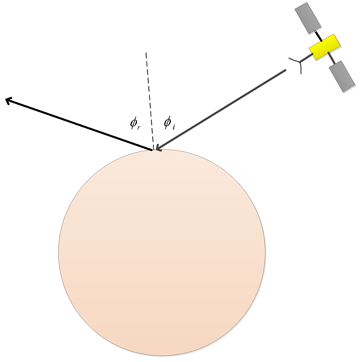
Figure 2.
The geometry of spacecraft (transmitter) and illuminated local surface.
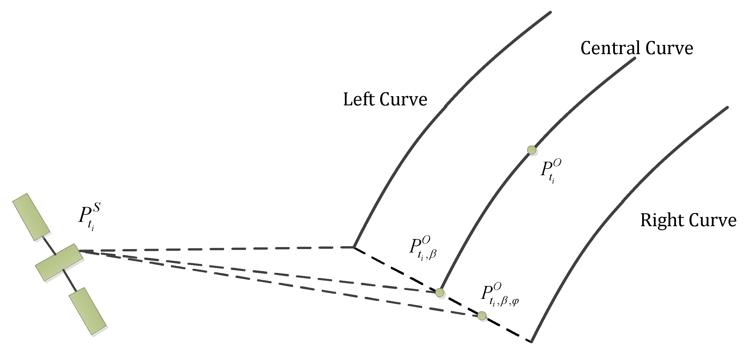
Figure 3.
The LX − LY − LZ local surface model to generate the elevation data.
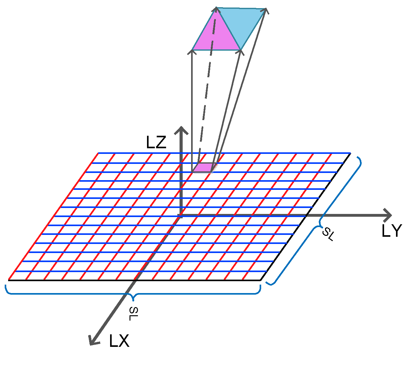
Figure 4.
The regular grid to generate the rough surface, random Gaussian surface and corrected Gaussian surface considering the irregularity length.
Figure 4.
The regular grid to generate the rough surface, random Gaussian surface and corrected Gaussian surface considering the irregularity length.

Figure 5.
Triangular facet element.
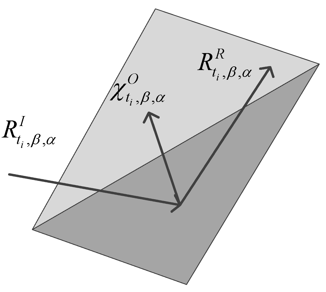
Figure 6.
Angle-based receiving condition conducted to determine the reception of reflected signals.
Figure 6.
Angle-based receiving condition conducted to determine the reception of reflected signals.
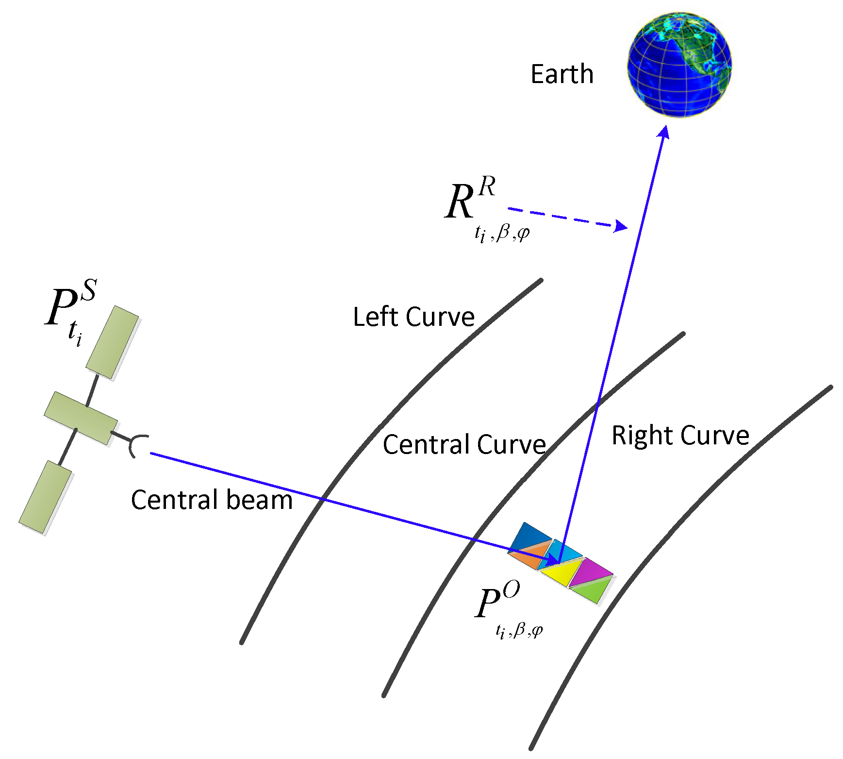
Figure 7.
Spatial positions of transmitter, surface and receiver where the sum of LIX and L2X are the total path length of the ray.
Figure 7.
Spatial positions of transmitter, surface and receiver where the sum of LIX and L2X are the total path length of the ray.
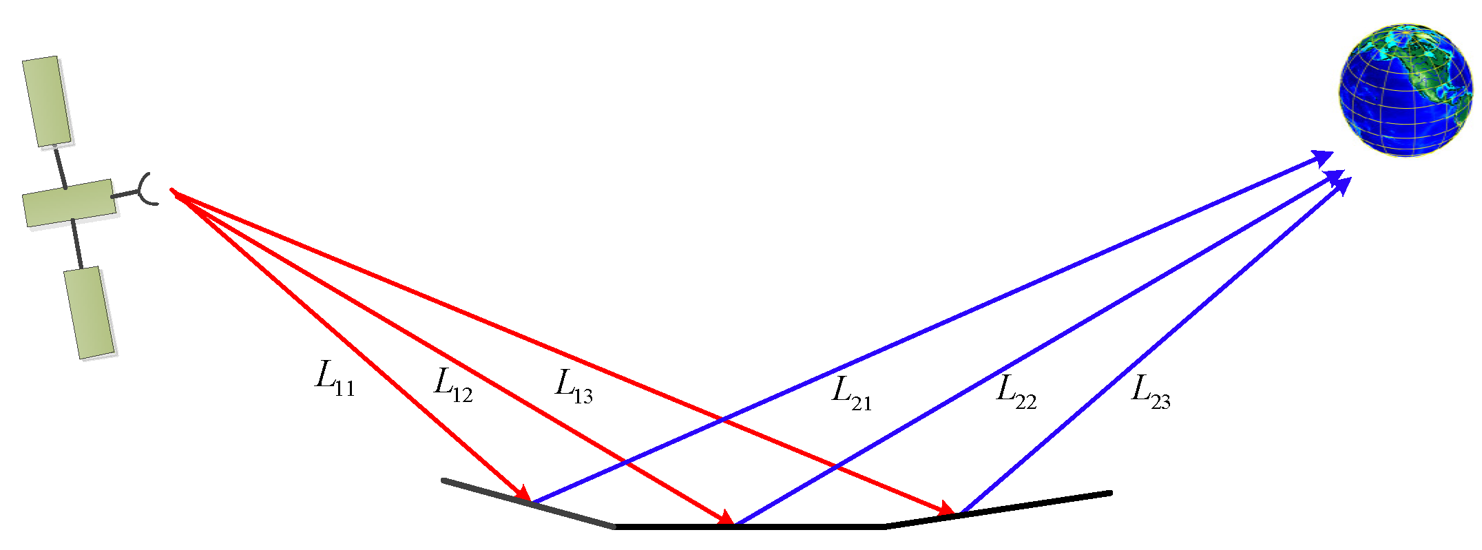
Figure 8.
The half-power bandwidth of the total simulated received RF signal (left column) in comparison with the analytical prediction given by Eq. (3) and the number of received radio waves (right column) under 5 independent runs of BIRDS with = 0.155° (a-b), = 0.135° (c-d), = 0.115° (e-f), = 0.095° (g-h), = 0.075° (i-j).
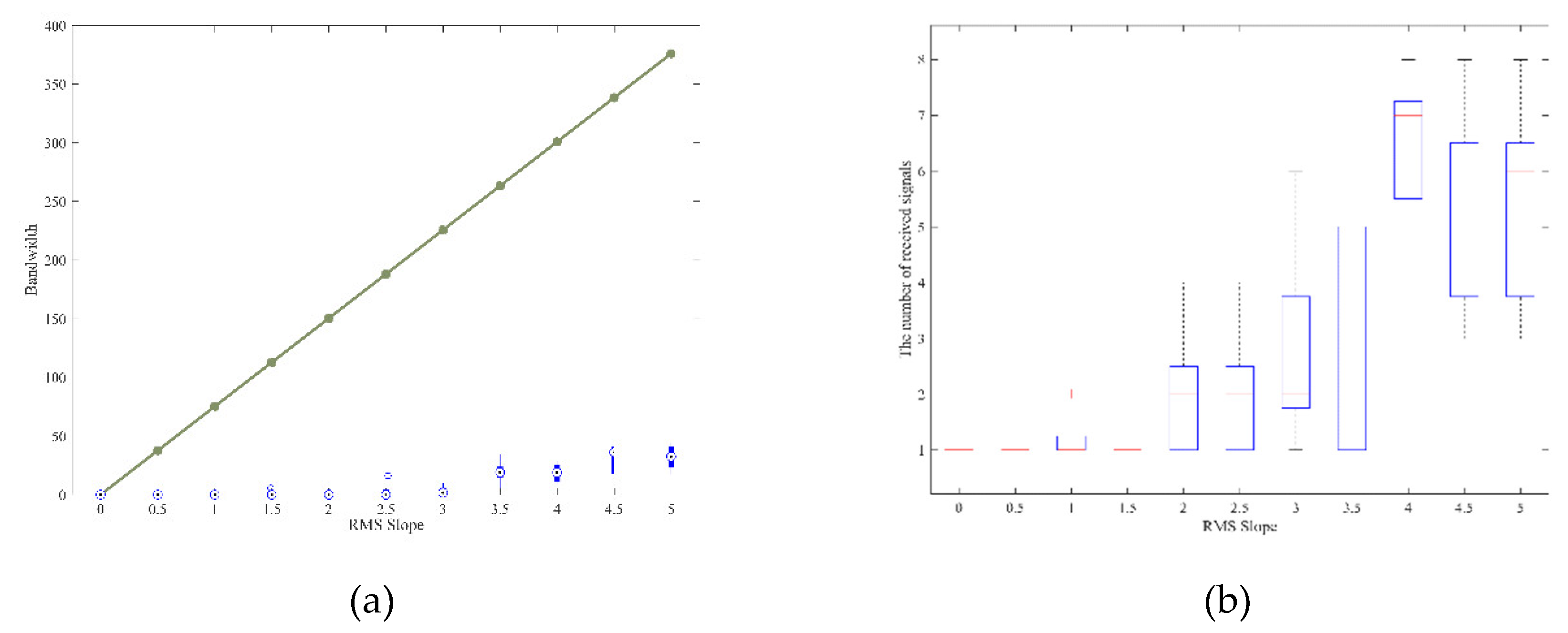
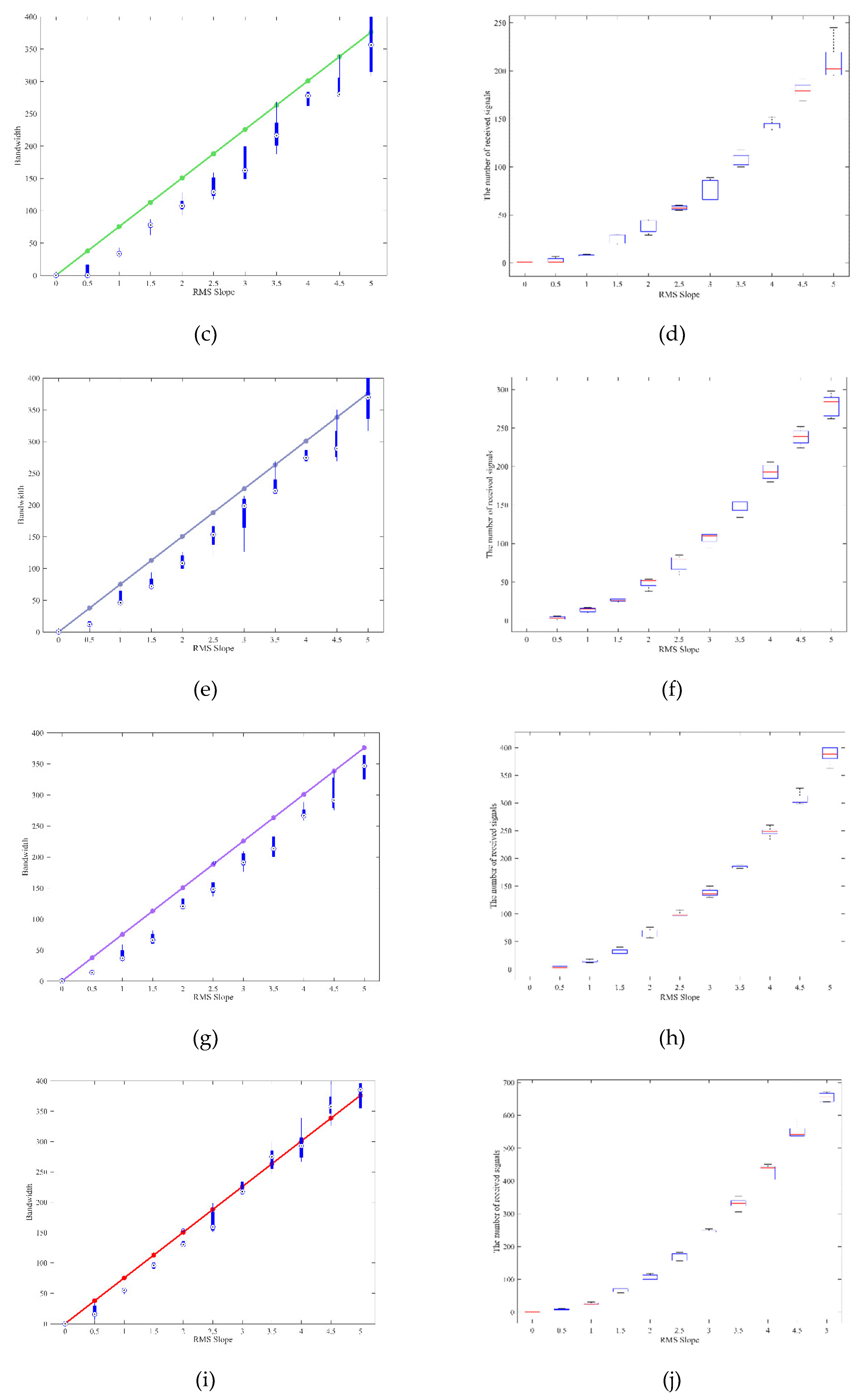
Figure 9.
The average value (left) and the standard deviation of the error between the numerical simulations and the analytical prediction given by Eq. (3) under different experimental conditions which vary the number of the received waves.
Figure 9.
The average value (left) and the standard deviation of the error between the numerical simulations and the analytical prediction given by Eq. (3) under different experimental conditions which vary the number of the received waves.
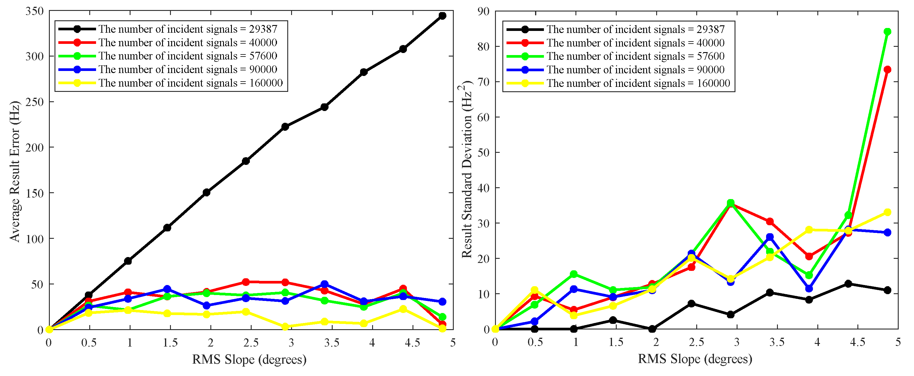
Figure 10.
The half-power bandwidth of the total simulated received RF signal in comparison with the analytical prediction given by Eq. (3), under 5 independent runs of BIRDS.
Figure 10.
The half-power bandwidth of the total simulated received RF signal in comparison with the analytical prediction given by Eq. (3), under 5 independent runs of BIRDS.
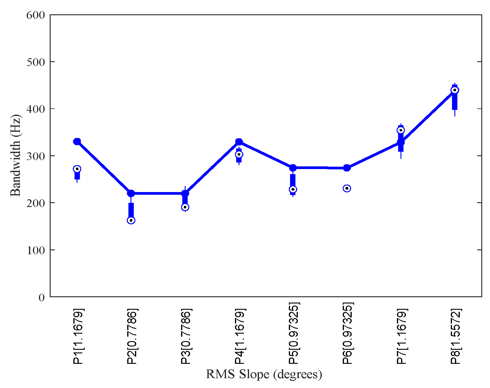
Table 1.
rms slopes of the generated surface based on different quantities of grid points, and the relative error (in brackets) when compared to the prediction given by Eq. (3).
Table 1.
rms slopes of the generated surface based on different quantities of grid points, and the relative error (in brackets) when compared to the prediction given by Eq. (3).
| rms H (km) | ζ with 29387 grid points | ζ with 40000 grid points | ζ with 57600 grid points | ζ with 90000 grid points | ζ with 160000 grid points (degrees) | ζ computed by Eq. (3) |
| 0 | 0 (0%) | 0 (0%) | 0 (0%) | 0 (0%) | 0 (0%) | 0 (0%) |
| 0.02 | 0.11136(77.12%) | 0.5632(15.73%) | 0.52963(8.84%) | 0.49545(1.81%) | 0.48783(0.25%) | 0.48663 |
| 0.04 | 0.22181(77.21%) | 1.1308(16.19%) | 1.0739(10.34%) | 0.99048(1.77%) | 0.97412(0.09%) | 0.97325 |
| 0.06 | 0.33319(77.18%) | 1.694(15.62%) | 1.5954(9.28%) | 1.4849(1.71%) | 1.4594(0.03%) | 1.4599 |
| 0.08 | 0.44457(77.16%) | 2.2535(15.77%) | 2.1339(9.63%) | 1.9785(1.64%) | 1.9483(0.09%) | 1.9465 |
| 0.1 | 0.54651(77.54%) | 2.8279(16.21%) | 2.6648(9.51%) | 2.4807(1.96%) | 2.4376(0.18%) | 2.4331 |
| 0.12 | 0.66127(77.35%) | 3.4209(17.16%) | 3.1748(8.73%) | 2.9608(1.40%) | 2.8965(0.80%) | 2.9198 |
| 0.14 | 0.77938(77.12%) | 3.9271(15.29%) | 3.7156(9.08%) | 3.4624(1.64%) | 3.4036(0.08%) | 3.4064 |
| 0.16 | 0.89038(77.15%) | 4.4841(15.18%) | 4.2575(9.36%) | 3.9631(1.80%) | 3.8912(0.20%) | 3.893 |
| 0.18 | 1.0112(76.91%) | 5.0768(15.92%) | 4.7752(9.03%) | 4.4374(1.32%) | 4.3644(0.35%) | 4.3796 |
| 0.2 | 1.1042(77.31%) | 5.6252(15.60%) | 5.3022(8.96%) | 4.9312(1.33%) | 4.8398(0.54%) | 4.8663 |
Disclaimer/Publisher’s Note: The statements, opinions and data contained in all publications are solely those of the individual author(s) and contributor(s) and not of MDPI and/or the editor(s). MDPI and/or the editor(s) disclaim responsibility for any injury to people or property resulting from any ideas, methods, instructions or products referred to in the content. |
© 2024 by the authors. Licensee MDPI, Basel, Switzerland. This article is an open access article distributed under the terms and conditions of the Creative Commons Attribution (CC BY) license (http://creativecommons.org/licenses/by/4.0/).
Copyright: This open access article is published under a Creative Commons CC BY 4.0 license, which permit the free download, distribution, and reuse, provided that the author and preprint are cited in any reuse.
MDPI Initiatives
Important Links
© 2024 MDPI (Basel, Switzerland) unless otherwise stated


