Preprint
Article

Rectangular Spiral Inward-Outward Alternating- Flow Polymer Thermal Collector for Solar Water Heating System—A Preliminary Investigation under Seri Iskandar, Malaysia Climate

Altmetrics

Downloads

341

Views

55

Comments

0

A peer-reviewed article of this preprint also exists.

Submitted:

20 May 2024

Posted:

21 May 2024

You are already at the latest version

Alerts
Abstract
A flat-plate unglazed solar water heater (SWH) with polymer thermal absorber was developed and tested. Polymer thermal absorber as a viable alternative to metal thermal absorber that is found in most SWH systems. The performance of this polymer SWH system is measured based on inlet and outlet water temperature, water flowrate, ambient air temperature and solar irradiance. The polymer thermal absorbers are hollow Polyvinyl Chloride (PVC) pipes with 20mm external diameter and 3 mm thick, painted in black to enhance radiation absorption. The pipes are arranged in a rectangular spiral inward-outward opposing-flow (RSioof). The collector pipes are placed in a 1 m2 square enclosure with bottom insulation and reflective surface for better radiation capture. Water circulation is a closed loop with a 16-liter uninsulated storage tank, driven by a pump and controlled by valves to maintain a mass flow rate of 0.00031 to 0.00034 kg/s. The test was conducted under partially clouded sky from 9 am to 5 pm, with solar irradiance between 105 and 1003 W/m2 and 27-36oC ambient air temperature. The SHW produced outlet hot water at 65oC by mid-day and maintained the storage temperature at 63oC until the end of test duration. Photo-thermal energy conversion was recorded with 23% maximum value. Results indicate that a flat plate solar water heater with polymer thermal absorber in RSioof design can be an effective alternative to the metal thermal absorber solar water heater and can be further optimized with glazing and tube sizing.
Keywords: 
Subject: Engineering  -   Energy and Fuel Technology

1. Introduction

The outer layer of the earth’s atmosphere receives 174 petawatts (PW) of solar radiation. Around 30% of this radiation is bounced back to space, and the remaining 122 PW is absorbed by clouds, oceans, and land masses. The amount of solar energy reaching land surfaces exceeds world’s energy demand. However, due to intermittent availability of sunshine as well as low energy conversion efficiencies of solar energy conversion systems, a large quantity of this free energy remains untapped. Most population on earth reside in regions with annual sunlight radiation rates of between 3.5 and 7.0 kWh/m2 or 150 to 300 W/m2. With this tremendous amount of solar energy reaching the surface of the earth, there should be more efforts to benefit from the most abundant free energy available. Solar energy can be harnessed by various technologies, mainly categorized into photovoltaic and solar thermal, that would reduce the dependance to non-renewable energy resources.
Most of solar irradiation reaching the earth's ground has a wavelength within 300–2500 nm, which covers the UV light (<380 nm), visible light (380–780 nm, and near infrared (NIR) light (>780 nm). The thermal band of solar irradiance, depicted in Figure 1, can be converted to thermal energy in liquid and gaseous heat transfer fluids such as water, air and nanofluids [1]. One of the simplest technique is direct water heating that is widely used in residential and commercial sectors. A Solar Water Heating (SWH) system typically comprises of solar collectors, storage tank, heat exchangers and pumps. SWH system can achieve thermal conversion efficiency of 70% as compared to around 17% for photovoltaic system, with the main contributor to its thermal efficiency improvement being the high convective heat transfer coefficient [2]. In 2010, around 70 million houses worldwide benefited from SWH system, which are not only environmentally friendly but also require minimal maintenance and operation cost compared to other solar energy applications, along with an attractive payback period of 2–4 years [2]. There are four major classifications of SWH by its thermal absorbing mechanism. These are: 1. flat plate collectors [3], 2. hybrid photovoltaic/Thermal collectors producing both electricity and heat energy [4], 3. evacuated tube collectors and 4. compound parabolic collectors [5]. Flat plate solar collectors in particular, are generally designed for working temperatures between 40 and 60°C, making them ideal for domestic hot water applications [6]. The global market for solar water heaters was valued at 4.7 billion dollars in 2019 and is anticipated to increase at a rate of 6.1% from 2020 to 2027 to reach 6.7 billion dollars [7].
In Malaysia, SWH is becoming more popular in its residential area due to its ability to reduce household electricity cost. As most of the SWH systems are equipped with pump, there would still be some extent of electricity costing to power the pump which aids water circulation, but the electricity cost to operate SWH system is much lower than to operate electric water heater. However, the SWH system has a high initial cost. The range of prices for a SWH system in Malaysia would come around MYR4,000.00 to MYR10,000 depending on the capacity of the tank in the system. Most of the SWH available to Malysia’s market are passive flat plate type equipped with metal heat absorber. Metal tubes such as copper or aluminum are used as heat absorbers due to their high thermal conductivity. Unfortunately, the downsides of metal heat absorbers is that they are more susceptible to internal tube scaling which eventually lead to early failure [8]. During extended operation duration, as the solubility range of the heat transfer fluid in metal tubes exceeded certain limits, ions will leave the solution and adhere to the metal pipe walls. Over time, these ions accumulate to form what appear to be scales all over the inside of the pipe. Scaling build-up in the long term can constrict water flow as it decreases the effective pipe diameter. Besides, scaling build-up in the metal pipe of a heat absorber will also affect the thermal conductivity of the pipe, hence, decreasing the heat absorbers efficiency.
One way to overcome the high initial cost and maintenance challenge is to use alternative material for thermal absorber tubes. Among others, polymer tube, which is widely available and reasonably priced, is a very practical option. Polymers tubes are cheaper, non-corrosive, and easy to fabricate into thermal collector. By optimizing the geometry, layout, fluid flow rate and other related factors, comparable performance can be achieved. Many polymer and plastic materials have been tested for the SWH systems. Sopian et.al used thermoplastic natural rubber (TPNR) in a thermosyphon type SWH, produced 65oC hot water with photo-thermal conversion efficiency of 72% [8]. The used of ethylene propylene diene monomer (EPDM), a petroleum-based product has also been explored [9]. Other polymer materials explored include polyethylene (PE) and polypropylene (PP) in a thermosyphon SWH system, with over 90% maximum photo-thermal conversion efficiency, producing 60oC hot water operating under a 22 MJ/m2day solar irradiance [10]. Polyethylene tubes can replace aluminum tubes with up to 95% thermal efficiency with four times cheaper to manufacture [11].
Another factor affecting the performance of SWH is the tube geometry and layout that optimized heat transfer fluid residence time in the SWH thermal collector. In addition, the heat transfer rate is increased by elevating turbulence. Collector tubes improvements can be achieved by a number of techniques such as twisted tape inserts, perforated twisted tape inserts, wire coil inserts, wire mesh etc. in the flow passage [5]. For example, inserting steel wire coil in the collector tube increased the heat transfer rate by 200% for mass flow rates in the range 0.011–0.047 kg/s, producing 14–31% increase in average thermal efficiency [12,13]. Inserting helical twisted tape with different twist ratios inside the copper tubes resulted in increased turbulence, thus reduced the collector area requirement by 8–24% for a given efficiency [14]. In terms of tube layout, the most common design is straight riser tube and serpentine.
In this work, a novel tube layout coined as RSioaf (rectangular spiral inward-outward alternating-flow) was developed and tested. It combined the benefit of using polymer material and increasing water residence time in the thermal collector while more uniformly absorbing solar radiation over the surface of the thermal collector. PVC is selected as the tube material. PVC possesses a good maximum temperature range of 75-100oC and excellent hydrolysis stability. However its poor UV radiation resistance can pose a challenge in the long run [15].

2. Materials and Methods

2.1. RSioaf Polymer Thermal Collector

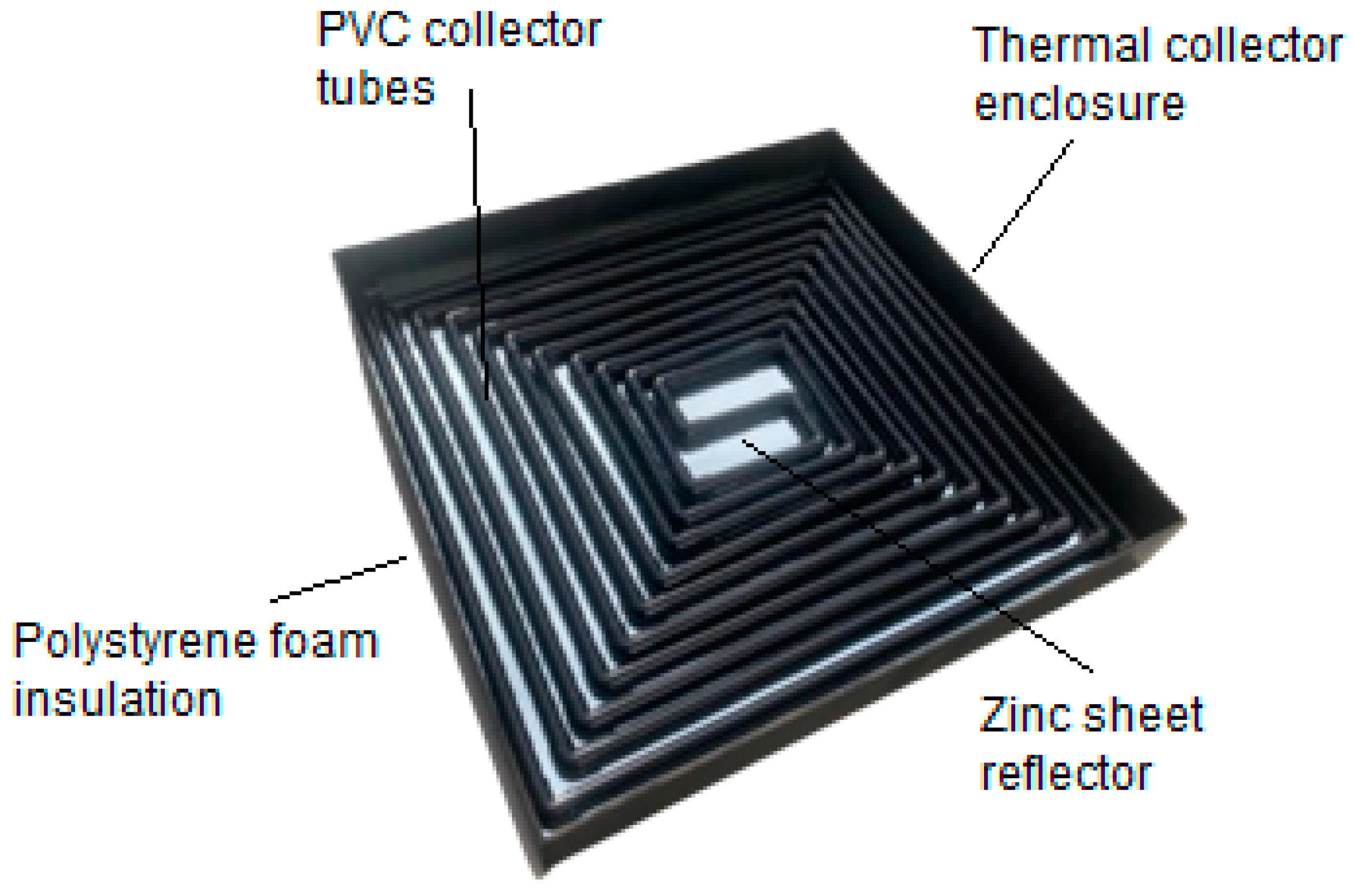
The polymer thermal collector consists of several components which made up the whole system. The most crucial component in the SWH system is the rectangular spiral inward-outward alternating-flow (RSioaf) polymer thermal absorber. The polymer thermal absorbers are made from hollow Polyvinyl Chloride (PVC) tubes with 20mm external diameter and 3mm thickness. The tubes were cut to various lengths and are inter-connected by elbows using a special plastic glue. To form the RSioaf patterns, the pipe is connected initially from both the inlet and outlet pipe, working inside into the middle of the pattern, resulting in a total length of 24 meters for the thermal absorbers in this design. To further aid heat transfer, the tubes are coated with black paint to ensure an effective heat radiation absorption. The 3D renders of the RSioaf design, alongside the direction of water flow in the tubes is shown in Figure 2. The solar collector enclosure which houses the RSioaf polymer thermal absorber is a 1-m2 square box made from plywood. The bottom of the box is insulated with polystyrene foam and covered by a zinc sheet reflector to maximize thermal absorbance by reflecting the incoming sun radiance to the lower part of the tubes shown in Figure 3. Table 1 lists some of the main parameters of the tested Polymer SWH system tested with reference to a copper tube serpentine SWH system which was previously researched [16].

2.2. Experimental Setup and Procedures.

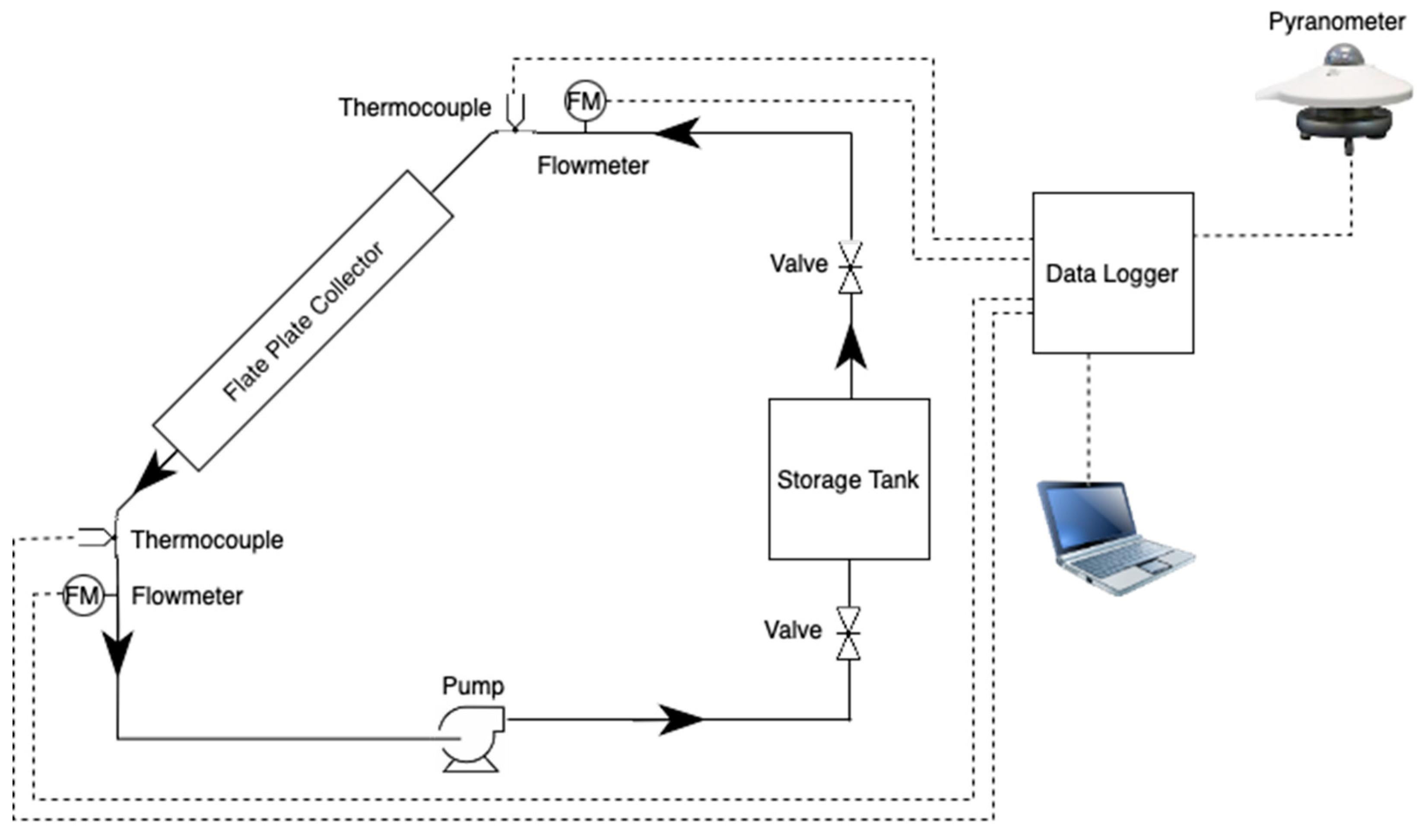
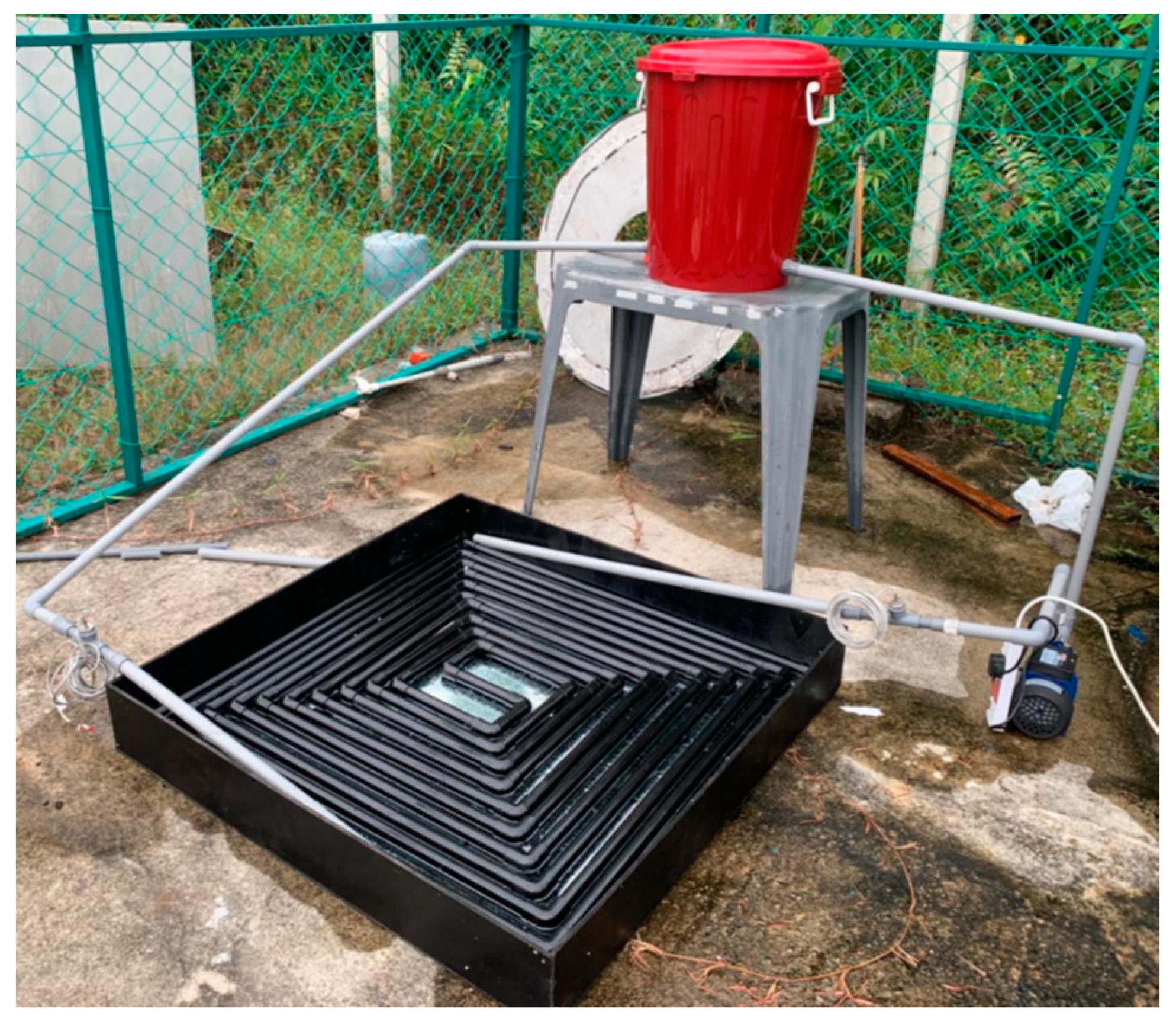
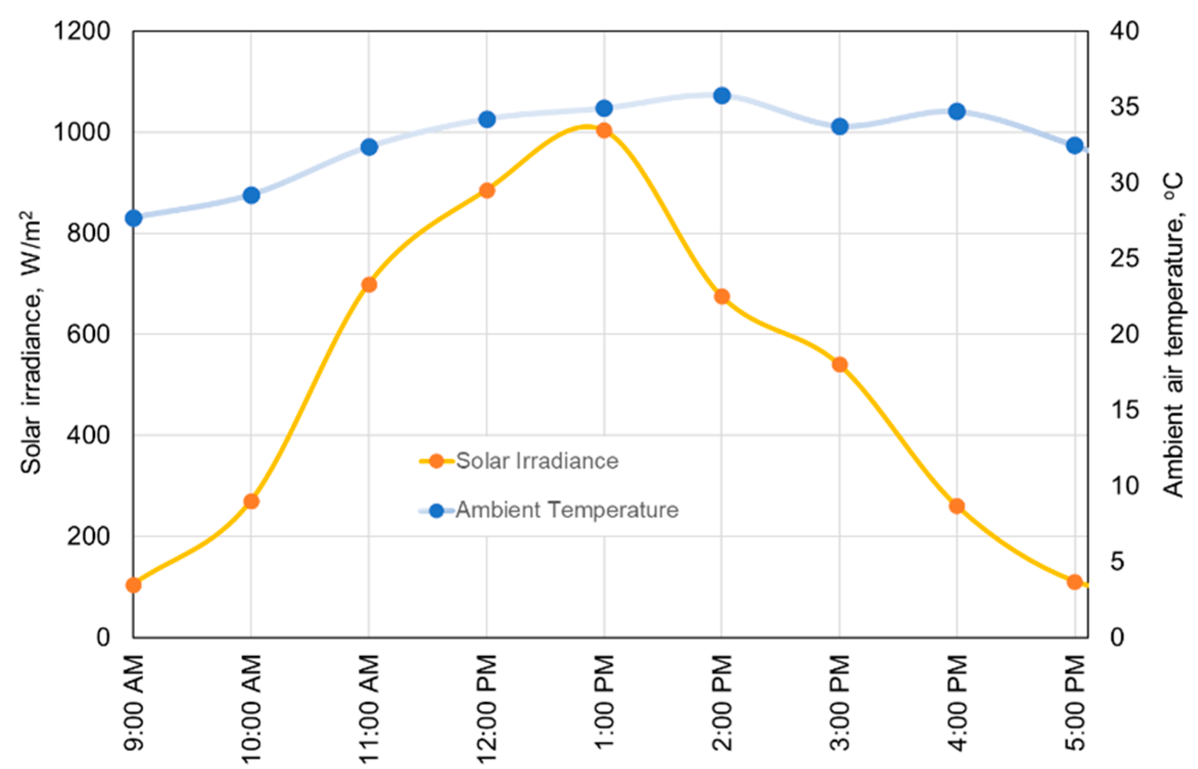
The schematic of the system experiment is shown in Figure 4. The physical setting is shown in Figure 5. The flat plate collector is mounted on the stand, inclined at 4.5o from horizontal, facing south, corresponding to the location of the test (Seri Iskandar, Malaysia 4.3590° N, 100.9849° E). The system utilized a closed-loop water circulation with an uninsulated 16-liter storage tank, powered by a 0.5 hp centrifugal pump. Two valves, at the inlet and outlet of the water tank, are used to maintain a mass flow rate in the range of 0.00318-0.00345 kg/s which is consequently measured via flowmeters connected to the inlet and outlet of the flat plate collector. Solar irradiance data is measured at every 1-minute interval by a photodiode pyranometer, while the inlet and outlet water temperatures were simultaneously monitored by k-type thermocouples. The entire data acquisition process was overseen by a Hioki MEMORY HiLOGGER LR8431 data logger and subsequently processed by a desktop computer. The experimental period, conducted under partially cloudy skies, spanned from 9 am to 5 pm in April 2023 at Universiti Teknologi PETRONAS Solar Research Park. Throughout the experiment, the tropical climate exhibited solar irradiance levels ranging between 105 and 1004 W/m2 with ambient air temperatures fluctuating between 27-36°C, as illustrated in Figure 6. Interestingly, the ambient temperature remained relatively high even during periods of lower irradiance in the afternoon, attributable to significant cloud shading during those intervals.

2.3. Energy Model

The energy absorbed by the solar collector is given in equation (1). This equation calculates the energy Qa absorbed by the thermal collector, it is measured in units of energy (Joules or kilojoules). It is determined by the product of the water mass flow rate m, the specific heat capacity of water cp​, and the temperature difference between the outlet temperature To​ and the inlet temperature Ti​. The mass flow rate, measured in kilograms per second (kg/s), determines the rate at which heat is transferred from the collector to the water. Higher flow rates can increase the efficiency of heat transfer but may require more energy to pump the water. Whereas the specific heat capacity, measured in joules per kilogram-degree Celsius (J/kg°C), determines how much heat energy is required to raise the temperature of the water in the collector. The temperature difference, To – Ti, measured in degrees Celsius (°C), indicates the amount of heat absorbed by the water as it flows through the collector. A larger temperature difference implies more heat absorption. This formula represents the basic principle of energy transfer in the collector, where the water absorbs heat as it passes through the collector, ultimately contributing to the overall thermal efficiency of the system.
The photo-thermal conversion efficiency, ɳth, is derived from equation (2). It is calculated based on the heat absorbed by the collector (Qa​) and the solar energy received by the collector (Is​⋅Ac​). The efficiency is dependent on several factors; FR is the heat removal factor, representing the fraction of absorbed heat that is effectively transferred to the working fluid. It is influenced by factors such as the collector design and operating conditions. τ is the emissivity of the glazing material, which affects the amount of heat retained by the collector (1 in the case of unglazed). A lower emissivity means that the material retains more heat, increasing the efficiency of the collector. α is the absorptivity of the thermal collector tube, indicating the fraction of incident solar radiation absorbed by the collector. A higher absorptivity means that the collector absorbs more solar radiation, increasing its efficiency. UL is the overall heat transfer coefficient, representing the efficiency of heat transfer from the absorber surface to the working fluid. It depends on the collector’s design and fluid properties.
Ultimately, the equation shows how the efficiency of the system is influenced by factors related to the collector design, operating conditions, and environmental factors.
Q a = m ˙ c p T o T i
η t h = F R τ α F R U L T i T a I s = Q a I s A c

3. Results and Discussion

The solar water heating (SWH) system, a polymer tube with RSioaf collector design, underwent testing in the local climate of Seri Iskandar, situated on the central west side of Peninsular Malaysia. The test was conducted over a single day, from 9 a.m. to 5 p.m., in April 2023, with data collected and presented on an hourly basis. The solar irradiance and ambient temperature values, detailed in Figure 6, showcase the day's conditions. The initial value observed for solar irradiance was approximately 100 W/m2 at 9:00 a.m., gradually reaching a peak value of 1004 W/m2 by 1:00 p.m. Afterwards, it dropped slowly to a minimum value of 110 W/m2 at 5:00 p.m. The sky was partially cloudy throughout the day of the test, particularly after 1:00 p.m., leading to a notable decrease in irradiance from 1004 W/m2 to approximately 640 W/m2 at 2:00 p.m. The ambient temperature was recorded at 27°C at the start of the day, gradually rising to a maximum of 36°C at around 2:00 p.m. Due to cloudy sky, the temperature only dropped to 32oC by 5.00 pm.
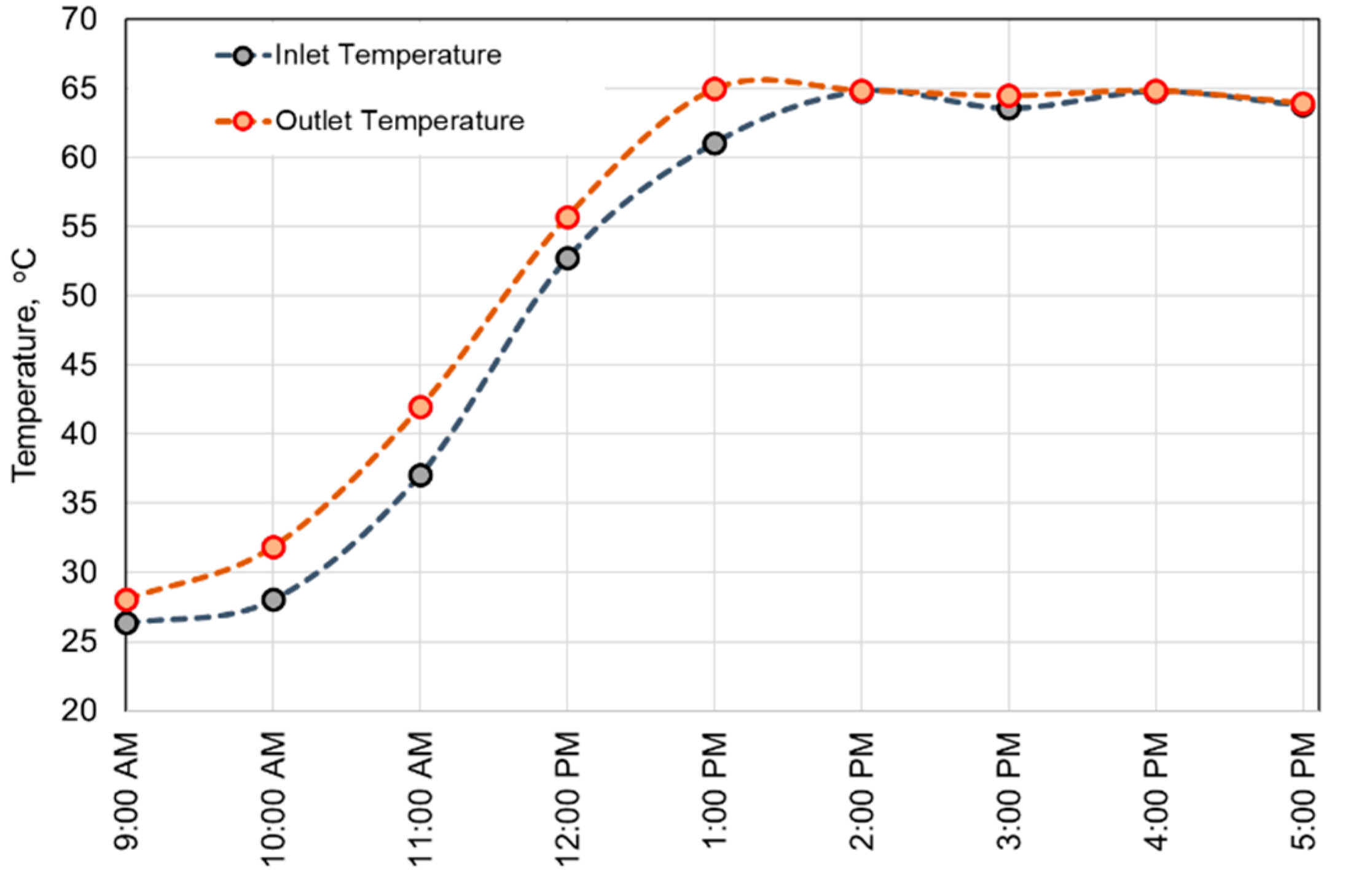
The hourly recorded water temperatures at the collector inlet and outlet, as illustrated in Figure 7, provide insight into the system's thermal behavior. Starting from 26.4°C at the inlet and 28.1°C at the outlet, the temperatures steadily rose, reaching peak values of 61.1°C and 65°C, respectively, at 1:00 p.m. Subsequently, both temperatures remained relatively constant at around 65°C for the duration of the test, indicating a thermal equilibrium where heat gain and loss were balanced. The narrowing temperature difference between the inlet and outlet temperatures is a result of the closed-loop water circulation nature of the system, demonstrating its ability to maintain stability in operation.
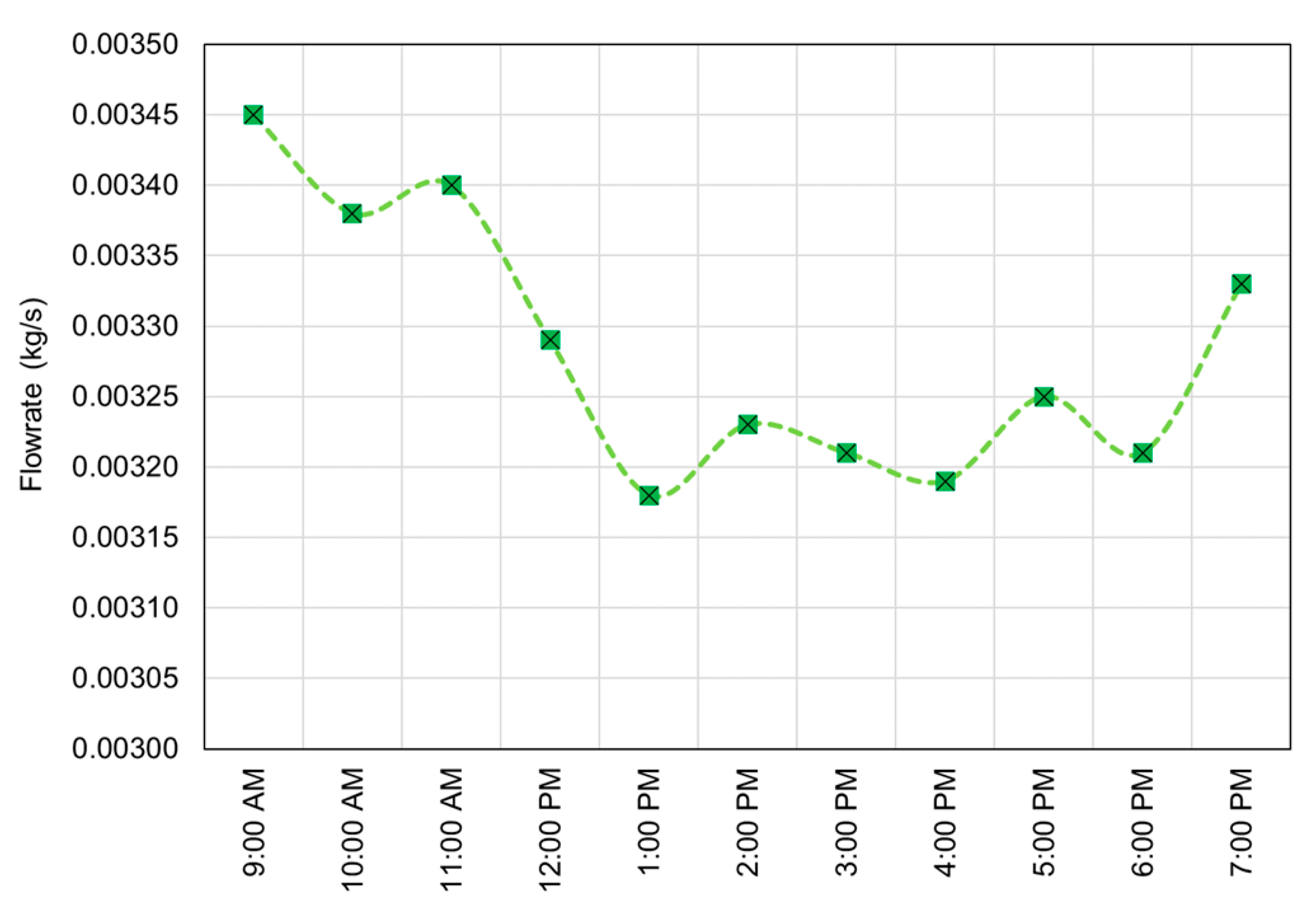
Figure 8 depicts the mass flow rate of water at the thermal collector inlet throughout the test period. Ranging from 3.18 g/s to 3.45 g/s, the flow rate is inversely related to water temperature. As temperatures increased, the mass flow rate decreased due to water expansion within the system. This phenomenon reduces both the amount and rate of heat absorption, contributing to a drop in efficiency at higher water circulation temperatures. Careful adjustment of the flow rate can lead to higher photo-thermal conversion efficiency. The control strategy is not developed for this experiment.
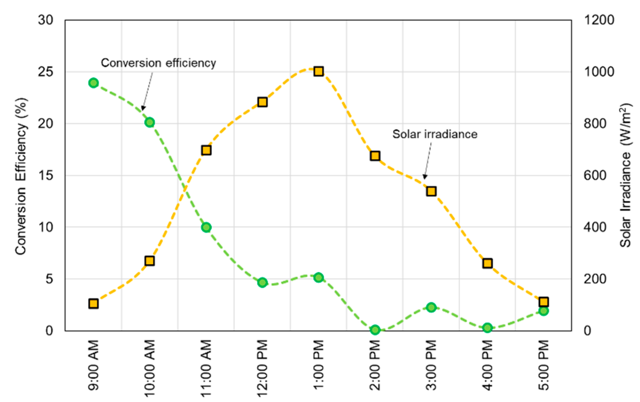
The photo-thermal conversion efficiency, shown in Figure 9, was calculated based on a closed-loop water circulation system, allowing for gradual heating of the water over the course of the day. The efficiency peaked at 24% in the first hour, gradually declining as the day progressed. This decline can be attributed to the narrowing temperature difference between the inlet and outlet temperatures over time, coupled with increasing solar irradiance towards midday. Post-1:00 p.m., the efficiency gradually declined and nearly reached zero by 2:00 p.m. This decrease was largely due to minimal temperature differences between the inlet and outlet, as shown in Figure 7. When the temperature difference approaches zero, the energy absorbed by the collector (Qa) also approaches zero, leading to an efficiency of zero according to equation (2). Although using metal tube may reach a similar maximum temperature more quickly due to its absorptivity and thermal conductivity, achieving the same efficiency with a polymer tube is feasible with appropriate mass flow rate adjustments. Increasing the residence time of water in the collector tube could lead to a higher maximum temperature achieved at a faster rate. Additionally, the absence of transparent cover called “glazing”, limits the system's performance. With glazing, more heat could be retained in the collector, enhancing heat transfer from the enclosed air to the collector tubes.
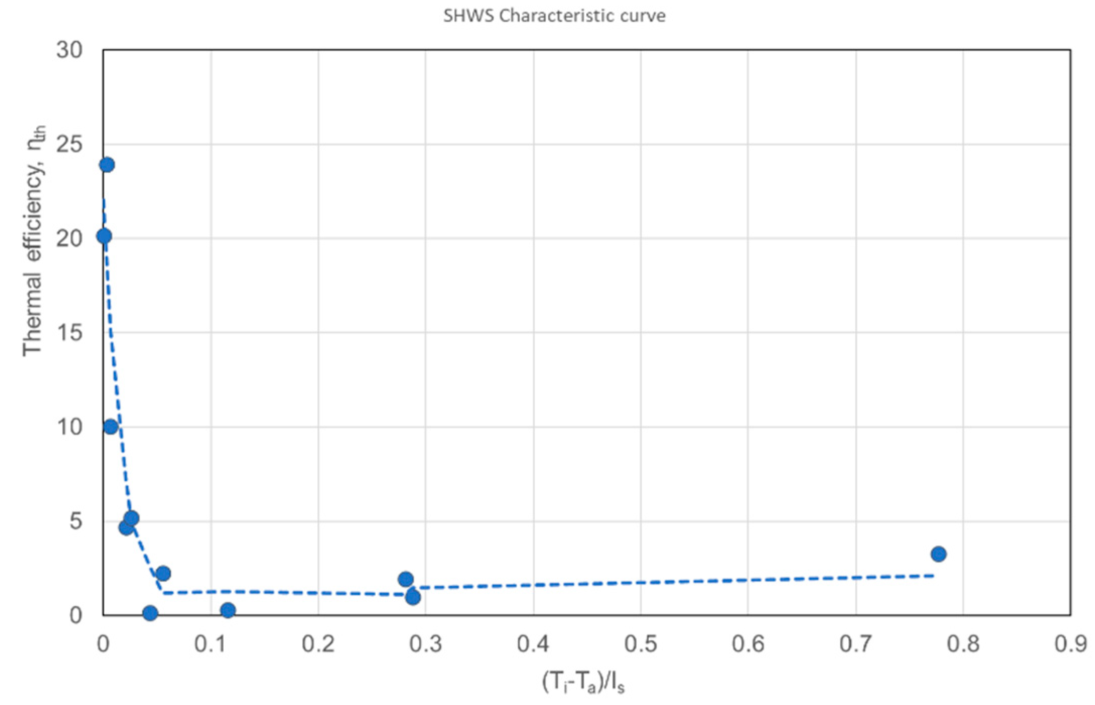
The collector efficiency ηth plotted against (Ti − Ta)/Is as shown in Figure 10. The slope of this curve, -FRUL, explained in equation (2), represents the rate of heat loss from the collector. Since this collector is unglazed, steeper slopes can be seen especially at the small temperature difference between inlet water and ambient. The maximum collector efficiency, FRτα, significantly relies on the optical properties of the collector. The moderately selective black paint applied on the thermal absorbers improved the overall thermal efficiency due to increased radiation absorption.
Overall, the performance of this polymer tube solar water heater has demonstrated a comparable outcome with the ones using metal tubes. Even though the thermal conductivity of PVC is 0.05% of that in copper, it can still produce hot water at a temperature of between 60oC and 70oC, which is a typical temperature setting for household applications. Increasing water residence time in the thermal collector through spiraling and the alternating cold and hot water flow can be considered to be the design advantage of RSioaf in producing the observed results. The photo-thermal conversion efficiency can be further expanded and improved with an open loop water circulation, where inlet water is kept constant around ambient temperatures. This will lead to a more comprehensive characterization of this renewable energy system. Further parametric and geometric refinement includes optimization of tube size, inclusion of glazing and regulating water flow.


4. Conclusions

The solar water heater with polymer thermal absorber (PVC tube) has been briefly tested and verified. The tubes are arranged in a novel design called Rectangular Spiral inward-outward alternating flow (RSioaf), with the aim to increased water residence time in the thermal collector and to provide a base for a well distributed water heating. Despite low thermal conductivity compared to copper tubes, this solar water heating system produced hot water up to 64oC, which is suitable for household applications. At a flowrate range of 3.10 g/s to 3.45 g/s, thermal conversion efficiency up to 23.94% was achieved. This work indicates that using PVC, a polymer thermal absorber, for solar water heaters is a practical solution for a cost competitive and technically simpler option. The performance of this system at the preliminary stage has shown promising results. With further refinement, by optimizing the flowrate, installing glazing as well as optimal tube material selection and sizing, the system is expected to serve its intended application and household hot water generation.

Author Contributions

Taib Iskandar Mohamad conceived the design of RSioaf thermal collector and the experimental setup and guided processing of raw data and the analysis of results. Mohammad Danish Shareeman Mohd Shaifudeen fabricated the thermal collector, built the experimental set up and conducted the experiment, performed data collection and analysis. Abu Bakar Nasir elaborated the mathematical model, experimental set up and procedures and provides some post experiment analysis of data.

Funding

This research was funded by Universiti Teknologi PETRONAS’s STIRF grant number 015LAO-041.

Conflicts of Interest

The authors declare no conflicts of interest.

References

  1. Huang, G., K. Wang, and C.N. Markides, Efficiency limits of concentrating spectral-splitting hybrid photovoltaic-thermal (PV-T) solar collectors and systems. Light: Science & Applications, 2021. 10(1): p. 28. [CrossRef]
  2. Sadhishkumar, S. and T. Balusamy, Performance improvement in solar water heating systems—A review. Renewable and Sustainable Energy Reviews, 2014. 37: p. 191-198. [CrossRef]
  3. Thakur, A., et al., Review of developments on flat plate solar collectors for heat transfer enhancements using phase change materials and reflectors. Materials Today: Proceedings, 2021. 45: p. 5449-5455. [CrossRef]
  4. Nižetić, S., et al., Implementation of phase change materials for thermal regulation of photovoltaic thermal systems: Comprehensive analysis of design approaches. Energy, 2021. 228: p. 120546. [CrossRef]
  5. Suman, S., M.K. Khan, and M. Pathak, Performance enhancement of solar collectors—A review. Renewable and Sustainable Energy Reviews, 2015. 49: p. 192-210. [CrossRef]
  6. Kizildag, D., et al., First test field performance of highly efficient flat plate solar collectors with transparent insulation and low-cost overheating protection. Solar Energy, 2022. 236: p. 239-248. [CrossRef]
  7. Eswara, C.A.C.S.P. Global Solar Water Heater Market by Type(Galazed and Unglazed) Capacity(100L, 150L, 200L and Others) and End User (Residential, Industrial, and Commercial): Opportunity Analysis and Industry Forecast, 2020-2027. Allied Market Reserach 2020 15 November 2022]; Available from: https://www.alliedmarketresearch.com/solar-water-heater-market-A07957.
  8. Sopian, K., et al., Thermal performance of thermoplastic natural rubber solar collector. Journal of Materials Processing Technology, 2002. 123(1): p. 179-184. [CrossRef]
  9. C.O. Frank, B.B., J.G. Gowan, Performance of non-metallic flate plate solar collectors, Solar Energy, 1984. 33: p. 305-309.
  10. de la Peña, J.L. and R. Aguilar, Polymer Solar Collectors. A Better Alternative to Heat Water in Mexican Homes. Energy Procedia, 2014. 57: p. 2205-2210. [CrossRef]
  11. Selikhov, Y., et al., The study of flat plate solar collector with absorbing elements from a polymer material. Energy, 2022. 256: p. 124677. [CrossRef]
  12. García, A., P.G. Vicente, and A. Viedma, Experimental study of heat transfer enhancement with wire coil inserts in laminar-transition-turbulent regimes at different Prandtl numbers. International Journal of Heat and Mass Transfer, 2005. 48(21-22): p. 4640-4651. [CrossRef]
  13. García, A., R.H. Martin, and J. Pérez-García, Experimental study of heat transfer enhancement in a flat-plate solar water collector with wire-coil inserts. Applied Thermal Engineering, 2013. 61(2): p. 461-468. [CrossRef]
  14. Jaisankar, S., T.K. Radhakrishnan, and K.N. Sheeba, Experimental studies on heat transfer and friction factor characteristics of forced circulation solar water heater system fitted with helical twisted tapes. Solar Energy, 2009. 83(11): p. 1943-1952. [CrossRef]
  15. Kim, S.i., et al., Design, analysis and performance of a polymer–carbon nanotubes based economic solar collector. Solar Energy, 2016. 134: p. 251-263. [CrossRef]
  16. Hasan, M.F., et al., Exergy Analysis of Serpentine Thermosyphon Solar Water Heater. Applied Sciences, 2018. 8(3): p. 391.
Figure 1. Solar irradiance wavelength spectrum [1].
Preprints 106960 g001
Figure 2. 3D renders of the RSioaf design with the water flow direction.
Preprints 106960 g002
Figure 3. RSioaf polymer tubes thermal collector.
Preprints 106960 g003
Figure 4. Schematic diagram of the experimental set up.
Preprints 106960 g004
Figure 5. Physical set up of the system.
Preprints 106960 g005
Figure 6. Solar Irradiance and Ambient Temperature plotted against Time.
Preprints 106960 g006
Figure 7. Hourly recorded inlet and outlet water temperature.
Preprints 106960 g007
Figure 8. Water mass flowrate through thermal collector tubes.
Preprints 106960 g008
Figure 9. Hourly conversion efficiency with respect to solar irradiance.
Preprints 106960 g009
Figure 10. Performance characteristic cof the polymer SWHS with RSioaf collector tubes design.
Preprints 106960 g010
Table 1. Parameters specification and comparison with a typical copper tube collector.
Parameter Polymer tube Metal tube1
Absorber Tube Material Polyvinylchloride Copper
Absorber tube design Rectangular Spiral inward-outward alternating flow Serpentine
Dimension of absorber plate 1.0 m2 0.6 m2
Pipe inner diameter 14 mm 10 mm
Pipe thickness 3 mm 1.5 mm
Glazing material -none- Tempered glass
Insulation PVC foam Glass wool & cork sheet
Collector tilt angle 4.5o 27o
Absorber thermal conductivity 0.19 W/m.K 401 W/m.K
Ambient temperature 27-36oC 30oC
Solar irradiance 105-1004 W/m2 900 W/m2
1 Data from previous work on similar subject [16].
Disclaimer/Publisher’s Note: The statements, opinions and data contained in all publications are solely those of the individual author(s) and contributor(s) and not of MDPI and/or the editor(s). MDPI and/or the editor(s) disclaim responsibility for any injury to people or property resulting from any ideas, methods, instructions or products referred to in the content.
Copyright: This open access article is published under a Creative Commons CC BY 4.0 license, which permit the free download, distribution, and reuse, provided that the author and preprint are cited in any reuse.
Prerpints.org logo

Preprints.org is a free preprint server supported by MDPI in Basel, Switzerland.

Subscribe

© 2024 MDPI (Basel, Switzerland) unless otherwise stated