1. Introduction
The Reusable Launch Vehicle (RLV) represents a novel space transportation tool that incorporates minor modifications to the basic configuration of conventional launch vehicles, enabling it to possess the capability of landing and returning. This advanced system offers several advantages, including reduced requirements for landing sites, a smaller technological leap, and relatively lower research and development costs [
1,
2,
3,
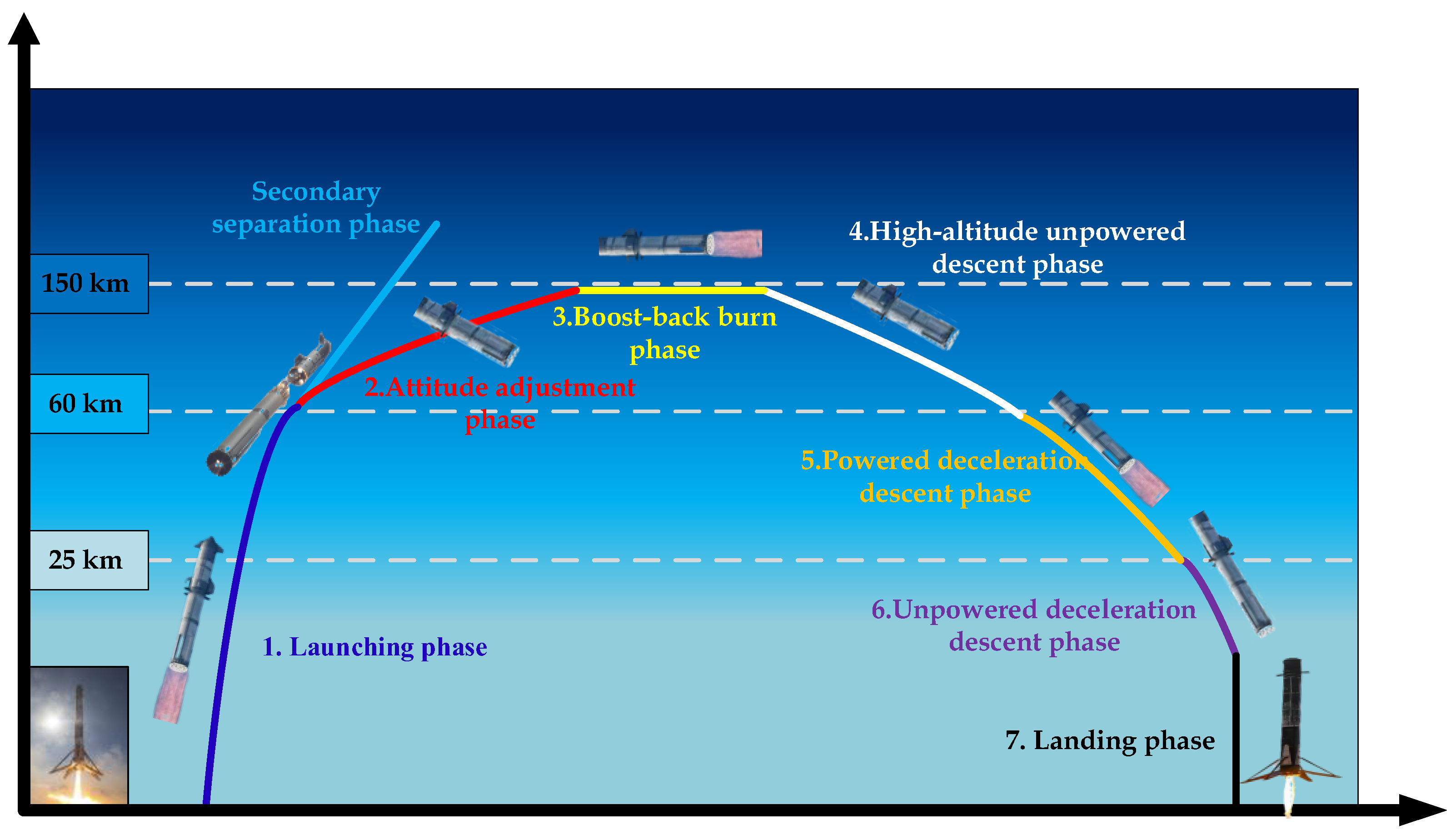
4]. Typically, the RLV undergoes seven distinct flight segments, which include the active phase, attitude adjustment phase, trajectory correction phase, high-altitude unpowered descent phase, powered deceleration descent phase, unpowered deceleration descent within the atmosphere, and the landing phase, as illustrated in
Figure 1. To effectively control the vehicle's attitude during these varied flight stages, the RLV must coordinate the operation of various heterogeneous actuation systems, such as the swiveling engines, grid fins, and the Reaction Control System (RCS) thrusters [
2]. The complexities presented by the extensive airspace and velocity envelopes, significant changes in dynamic characteristics, and high environmental uncertainties [
3] during the entire flight mission make it challenging to establish clear and precise kinematic laws and mathematical models for the RLV. Consequently, the design of a high-precision and robust anti-interference attitude control system for the RLV, which is subject to the influence of multiple heterogeneous actuators, and the unified description of all flight stages within a single control framework, are pivotal research directions in the field of aerospace launch vehicles [
2].
As a core function of the launch vehicle control system, attitude control utilizes data from sensitive devices, guidance signals, and navigation computations to generate control commands that manipulate the vehicle's rotational motion around its center of mass. This ensures stable flight and effective command tracking even under various disturbances and potential faults [
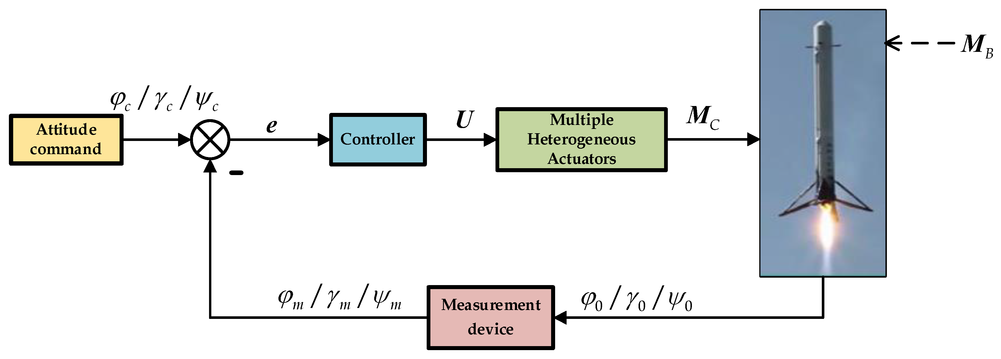
4]. As depicted in
Figure 2, for RLV, the significance of various heterogeneous actuators in attitude control is particularly pronounced. Inaccurate or delayed attitude control during the vehicle's return phase can lead to unsuccessful rocket recovery, which in turn affects the reusability and economic efficiency of the vehicle. Consequently, the selection of an appropriate control strategy and the design of a reasonable controller are crucial elements for the successful implementation of RLV attitude control.
Over the past half-century, the majority of launch vehicles have employed traditional PID control combined with correction networks for attitude control [
5,
6,
7]. However, with the enhancement of launch vehicle performance and control requirements, the vehicle body experiences greater disturbances, more severe parameter perturbations, and larger deviations during the execution of complex flight missions. PID controllers designed based on classical control theory use a single-tuned control gain with a limited adjustable range, making the design overly conservative and insufficient to meet the control requirements of launch vehicles [
8]. To enhance the adaptability of launch vehicles to changes in the flight environment, researchers both domestically and internationally have started to focus on modern control methods and intelligent control strategies, aiming to optimize the performance of launch vehicle attitude control systems. Virtually all classic and modern control methods have been applied to some extent in the design of attitude control systems. Among them, fuzzy control, as a simple and efficient intelligent control method, is particularly advantageous in launch vehicle attitude control due to its flexibility in handling non-precision, non-linearity, and time-varying complexities without relying on precise mathematical models of the system. It translates expert control experience into concise and easily understandable linguistic control rules, making it easier to leverage its advantages in simplicity, anti-interference, and robustness [
9]. However, fuzzy controllers are rarely used as a standalone solution for vehicle attitude control due to limitations in control precision, cumbersome debugging, and excessive reliance on expert experience. Instead, fuzzy control is often combined with other control methods. Wang Pei et al. [
10] proposed an anti-interference attitude controller based on fuzzy logic and PD control for launch vehicles, aiming to enhance the effectiveness and robustness of launch vehicle attitude control. R. Sumathi et al. [
11] designed a fuzzy-PID hybrid controller for launch vehicle engine attitude control, demonstrating that this controller completely eliminates overshoot and provides substantial stability. Chan-oh Min et al. [
12] introduced a control scheme using a Mamdani-type fuzzy PD controller for attitude control during the approach and landing phases of reentry vehicles, showing that this controller exhibits good control performance and robustness. Vladimir Melnic [
13] proposed a hybrid attitude controller for spacecraft that simultaneously utilizes fuzzy and PID controllers, adjusting the outputs of both controllers through a predetermined combination function. This approach integrates the robustness and rapidity of fuzzy control with the accuracy of PID control, although it is constrained by the fixed combination function and cannot fully exploit the individual advantages of the two controllers.
Furthermore, the simultaneous use of multiple control methods inevitably leads to an increase in the number of controller parameters and complicates the tuning process. Therefore, selecting an appropriate parameter optimization method is crucial for rapidly designing controller parameters and ensuring system performance during intensive launch missions. Particle Swarm Optimization (PSO) is a modern intelligent bio-inspired algorithm based on population search, proposed by Kennedy et al. [
14] in 1995 and developed through the simulation of bird flock foraging behavior. PSO and its improved algorithms have demonstrated excellent performance in solving various complex optimization tasks, particularly for the intricate and critical task of optimizing controller parameters. In recent years, they have been widely applied in the aerospace and control fields. Shi Qi et al. [
15] introduced PSO to determine the specific values of various controller parameters based on adaptive augmented control technology for launch vehicles, providing an effective approach for determining controller parameters. Remya S et al. [
16] tuned PID controller parameters based on an improved PSO algorithm, optimizing the RLV servo drive system. S. Bouallègue et al. [
17] proposed a parameter tuning strategy for PID-type fuzzy controllers using an improved PSO algorithm, and simulations verified the effectiveness and superiority of the proposed PSO-based PID-fuzzy control method. Housny H et al. [
18] introduced an adaptive multi-dimensional improved PSO algorithm and applied it to optimize the parameters of fuzzy controllers, enhancing the performance of fuzzy PID attitude controllers in quadrotor aircraft.
The remainder of this paper is structured as follows:
Section 2 establishes the launch vehicle attitude dynamics model based on the flight characteristics of RLV and individually models the various heterogeneous actuators in different flight segments.
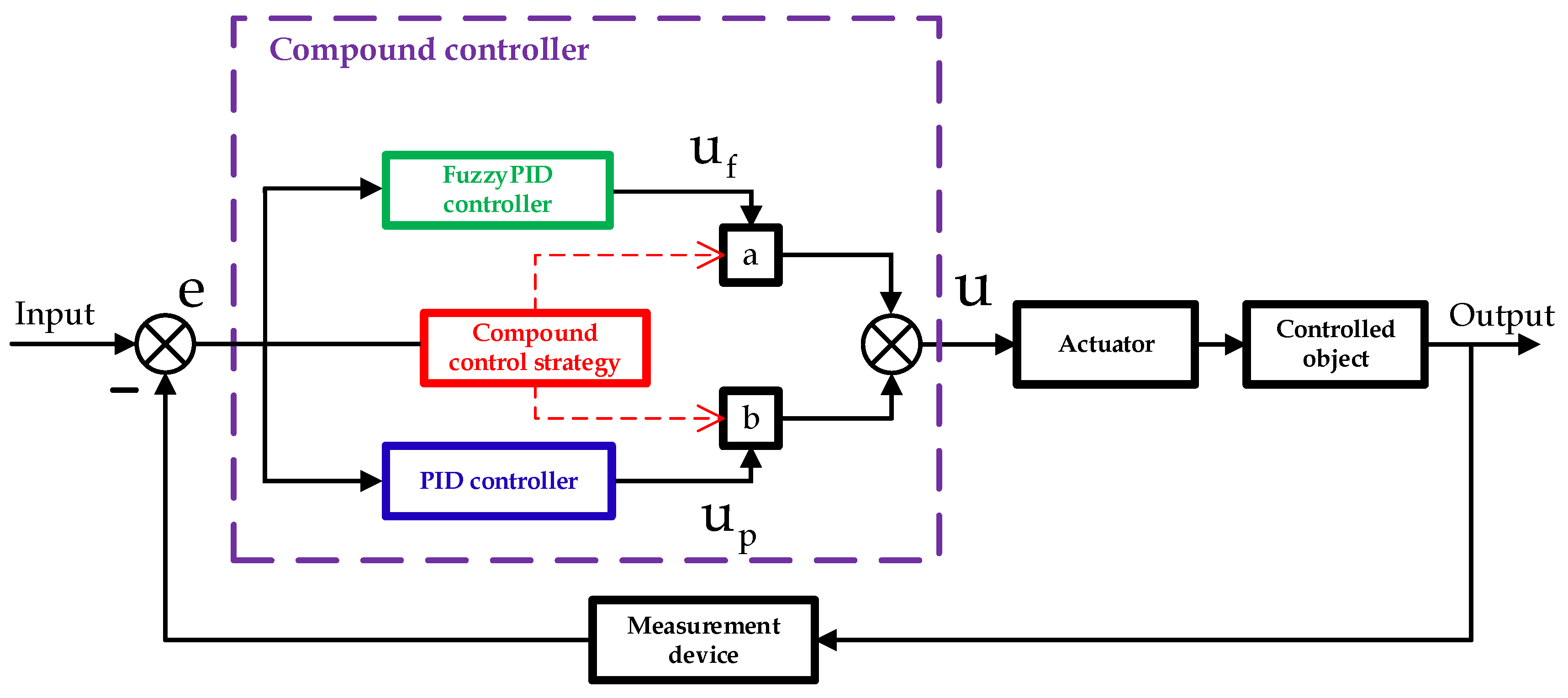
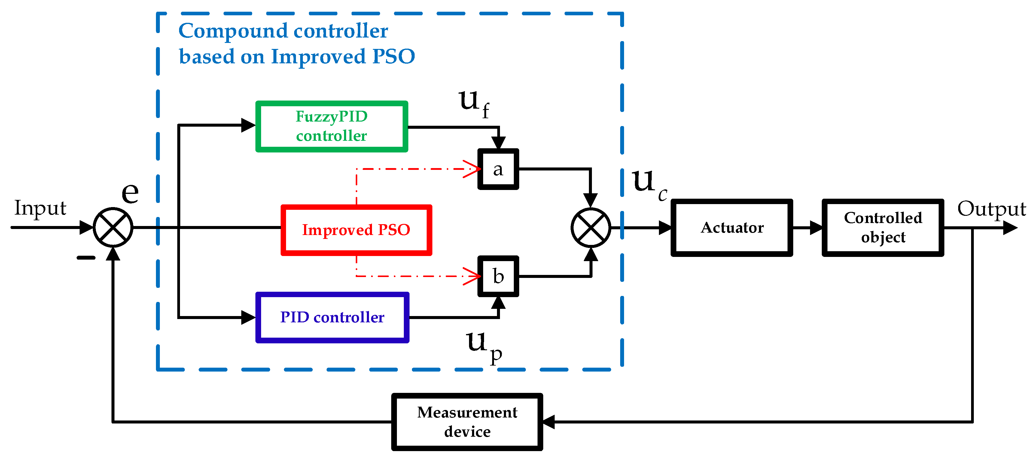
Section 3 designs the basic structure of the RLV compound attitude controller through the coordination of fuzzy PID and traditional PID for dual-mode combined control.
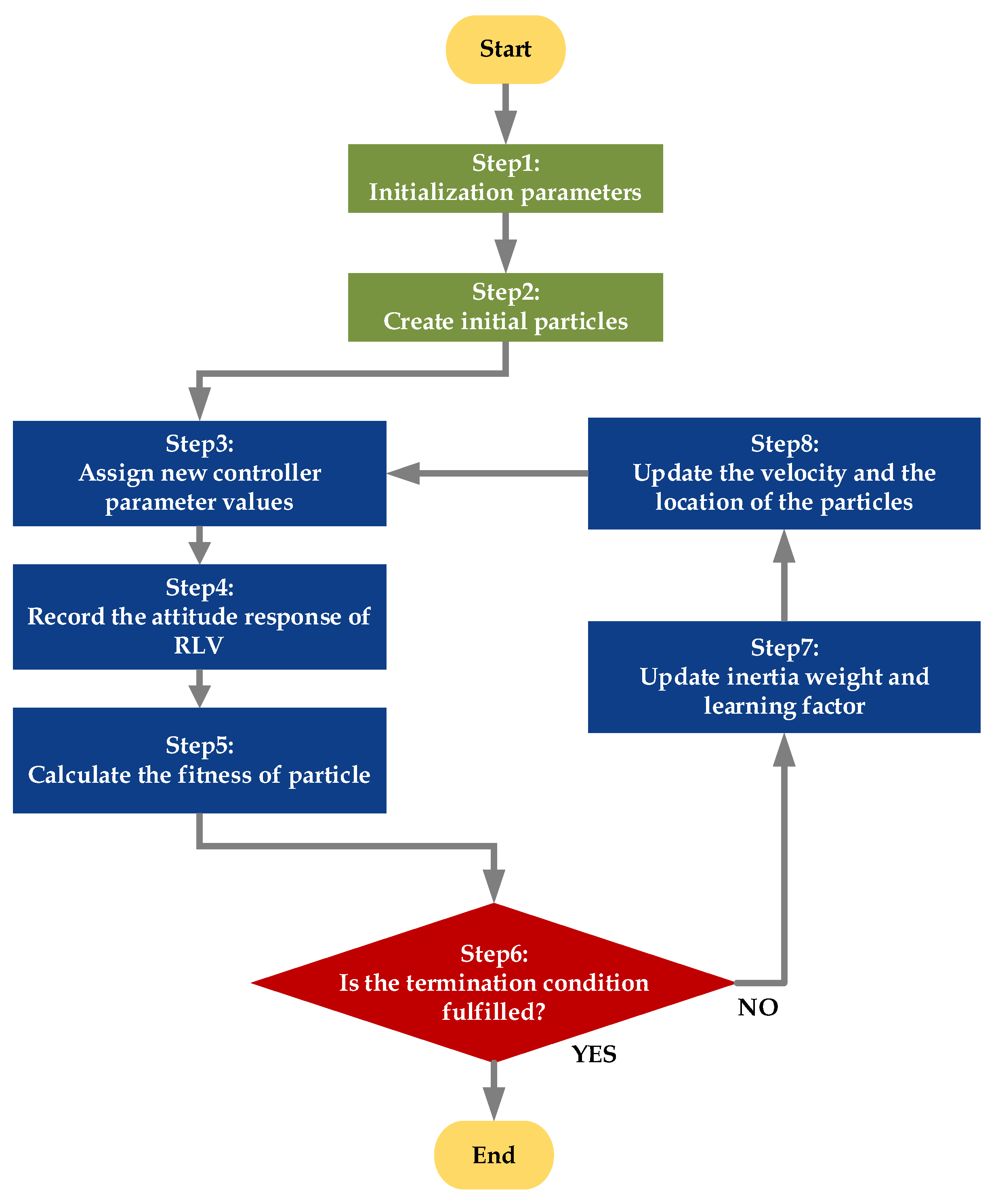
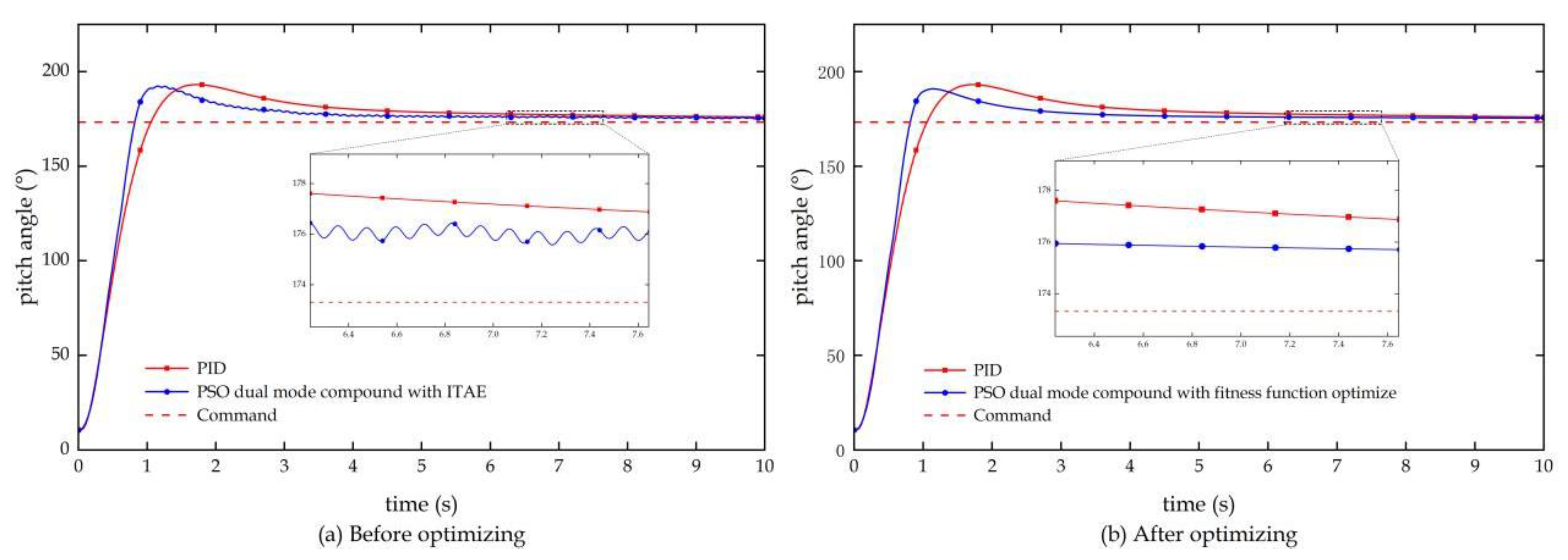
Section 4 optimizes the output weight parameters of the controller using the improved PSO algorithm, and adds an integral term of time multiplied by the absolute value of the second derivative of the error to the fitness evaluation function to assess the system's relative stability, addressing issues such as minor oscillations in the optimization results.
Section 5 conducts comparative simulation tests on the RLV flight states during the attitude adjustment and unpowered deceleration within the atmosphere phases to verify the comprehensive performance of the dual-mode compound attitude controller based on improved PSO. Finally, the research work presented in this paper is summarized.
2. Modeling of Reusable Launch Vehicle
2.1. Dynamics Modeling of Launch Vehicle Attitude
Neglecting the influence of the elastic vibrations of the vehicle body, this paper treats the launch vehicle as a rigid body, with its rotational dynamics equation around the center of mass as follows: [
2].
In the equation 1 and 2, represents angular momentum, represents the angular velocity of the vehicle body, and represents the moment of inertia of the vehicle body; represents the roll angle, represents the yaw angle, and represents the pitch angle; represents the moment term generated by the rocket engine thrust; represents the moment term generated by the Reaction Control System (RCS) actuators; represents the moment term generated by the grid fins; and represents the disturbance moment term.
Based on the rotational dynamics equation of the vehicle body around the center of mass, the attitude dynamics model of the RLV can be derived as follows:
Where, , , represents the control matrix, represents the control variables, and represents the transformation matrix between attitude angles and angular velocities.
Throughout the entire flight process of the launch vehicle, significant changes in flight conditions and various disturbances occur. However, the aforementioned modeling process does not consider these complex state changes. Therefore, based on the previously obtained attitude dynamics model, the influence of internal parameter uncertainties and external disturbances on the vehicle's attitude must be introduced [
19,
20]. Consequently, the final form of the launch vehicle's attitude dynamics model should be as follows:
Where,
represents the uncertainty term in the moment of inertia, and
represents the disturbance torque term, with the derivation process and specific form provided in literature [
21].
2.2 Modeling of Various Heterogeneous Actuators
Throughout the seven flight segments of the RLV's takeoff and landing, various heterogeneous actuation systems, including swiveling engines, Reaction Control System (RCS), and grid fins, need to switch their operations, and each system operates on different principles [
2]. Therefore, the specific forms of the control matrix and control variables in Equation (5) will also differ.
- (1)
-
During the active phase, flight attitude stability is controlled through swiveling engines, with their control matrix and control variables given as:
Where, represents the thrust of a single engine; represents the installation radius of the peripheral engines; represents the pivot point location of the engine; represents the position of the rocket's center of mass; , , and represent the equivalent swivel angles of the swiveling engines.
- (2)
-
During the attitude adjustment phase/high-altitude unpowered descent phase, in order to achieve large-scale and significant attitude reversals, direct force control is employed. The Reaction Control System (RCS) is installed at a location far from the center of mass as the actuation mechanism, with its control matrix and control variables expressed as:
Where, , and represent, respectively, the moments generated in three directions by the Reaction Control System (RCS).
- (3)
In the trajectory correction phase, the powered descent phase, and the landing phase, a single swiveling engine controls the pitch and yaw channels, while the RCS controls the roll channel. In this configuration, the control matrix and control variables are expressed as:
- (4)
During the atmospheric flight phase, attitude adjustments are made using the aerodynamic moments generated by the grid fins, with the control matrix and control variables expressed as:
Where, , , and represent the control moments of the rocket's grid fins; represents dynamic pressure; represents the reference area; represents the reference length; , , and represent the equivalent deflection angles of the grid fin surfaces.
From Equations (1) and (6)-(13), it can be observed that although the various heterogeneous actuators operate on different principles, the ultimate control variables for the launch vehicle's attitude dynamics model are in the form of combined external moments, that is, providing control moments to achieve control over the vehicle's motion around its center of mass. Therefore, a unified control framework can be established, where the attitude angles serve as control commands, and the combined external moments act as the control variables for the vehicle's attitude, thereby achieving attitude control of the RLV.
5. Conclusion
This study addresses the imperative for high-precision and robust anti-interference attitude control in the operational profile of reusable launch vehicles (RLVs) by proposing an integrated control strategy that harmonizes PID with fuzzy PID controllers. Utilizing an advanced particle swarm optimization (PSO) algorithm, the research optimizes the output weight coefficients of these controllers, culminating in the development of an enhanced PSO-driven dual-mode composite attitude controller. This controller is adept at managing the intricate demands of the entire RLV flight spectrum.
To substantiate the efficacy of the proposed control system, this paper meticulously selects the attitude adjustment phase and the unpowered descent phase within the atmospheric re-entry as representative flight stages. A suite of step tracking and anti-interference tests are conducted and compared against traditional PID, fuzzy PID, and dual-mode switching controllers. The simulation outcomes are compelling, revealing that the dual-mode composite attitude controller, underpinned by the refined PSO, surpasses its counterparts across metrics of stability, agility, accuracy, and interference mitigation. This controller significantly bolsters the RLV's attitude control system's overall performance, empowering it to adeptly navigate the complexities of multi-stage flight missions.
Figure 1.
RLV flight profile.
Figure 1.
RLV flight profile.
Figure 2.
Basic principle of RLV attitude control system.
Figure 2.
Basic principle of RLV attitude control system.
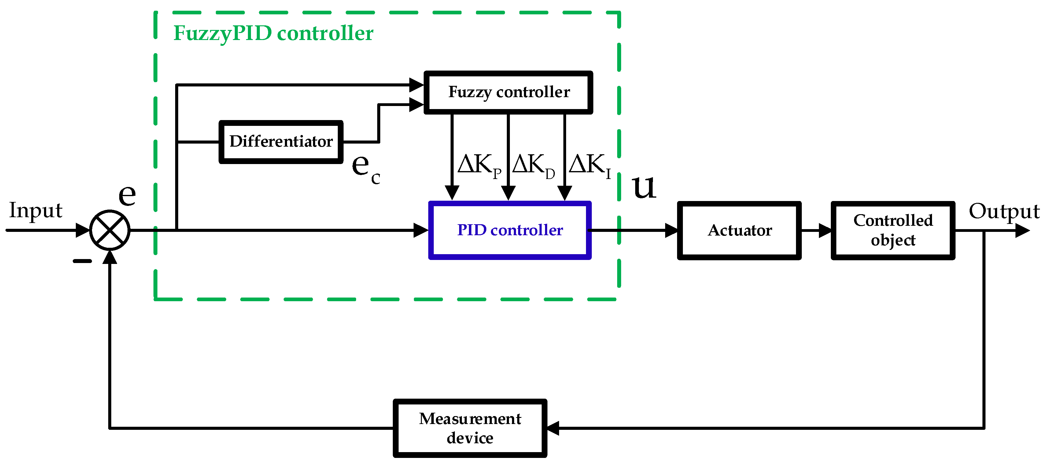
Figure 3.
Schematic diagram of fuzzy PID controller.
Figure 3.
Schematic diagram of fuzzy PID controller.
Figure 4.
schematic diagram of dual-mode composite controller.
Figure 4.
schematic diagram of dual-mode composite controller.
Figure 5.
Optimization flowchart of improved PSO algorithm.
Figure 5.
Optimization flowchart of improved PSO algorithm.
Figure 6.
Schematic diagram of dual-mode composite controller based on improved PSO.
Figure 6.
Schematic diagram of dual-mode composite controller based on improved PSO.
Figure 7.
Pitch angle response results before and after optimizing the fitness evaluation function.
Figure 7.
Pitch angle response results before and after optimizing the fitness evaluation function.
Figure 8.
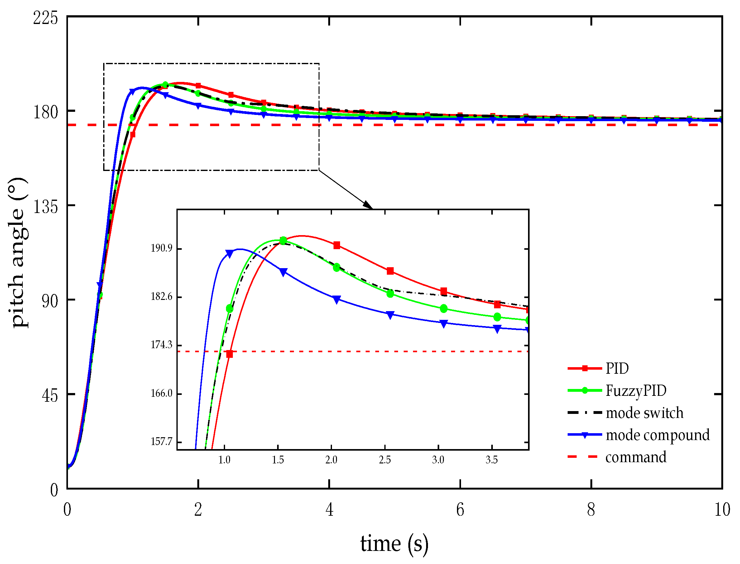
Test curve of Pitch angle response in the attitude adjustment section.
Figure 8.
Test curve of Pitch angle response in the attitude adjustment section.
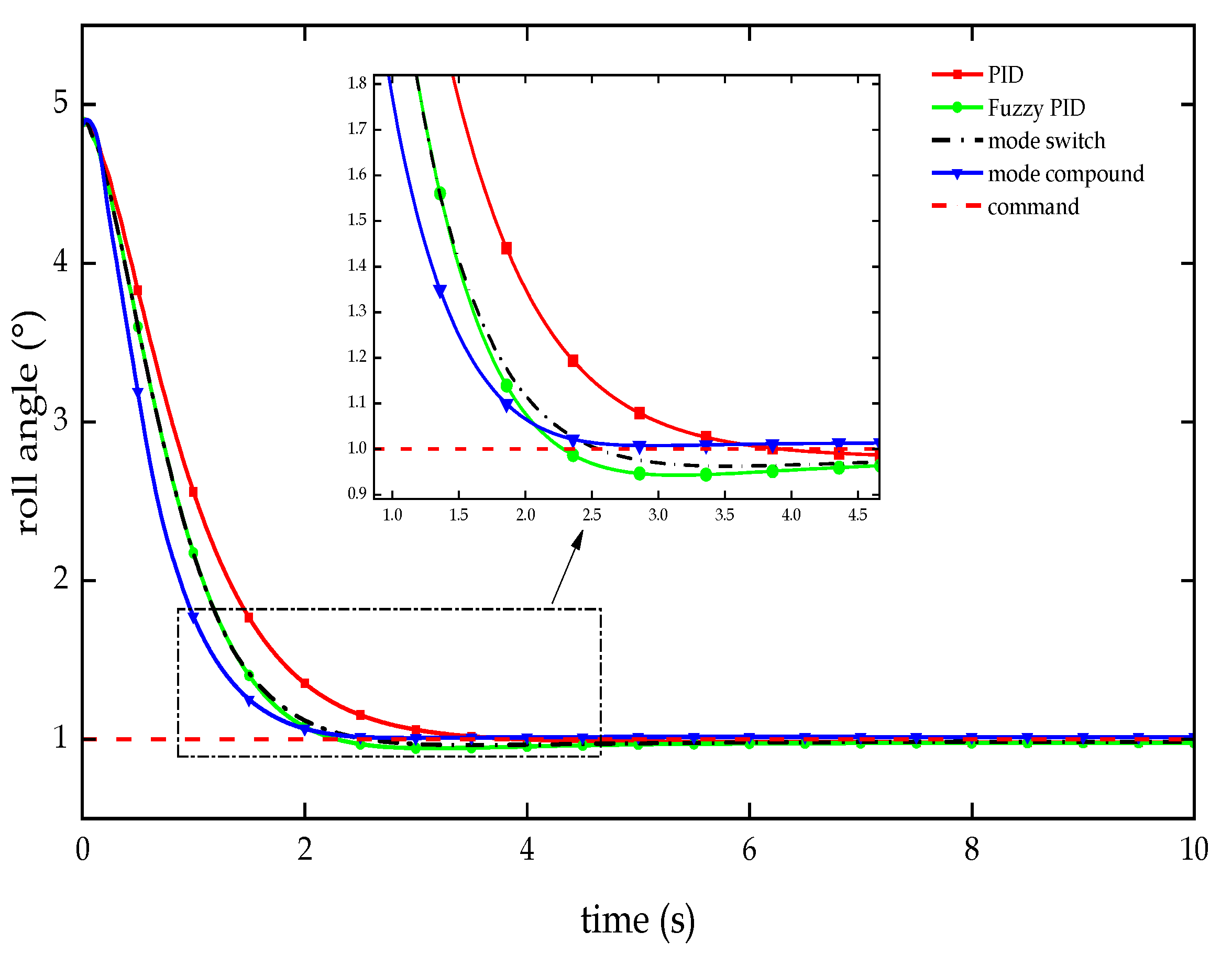
Figure 9.
Test curve of roll angle response in the attitude adjustment phase.
Figure 9.
Test curve of roll angle response in the attitude adjustment phase.
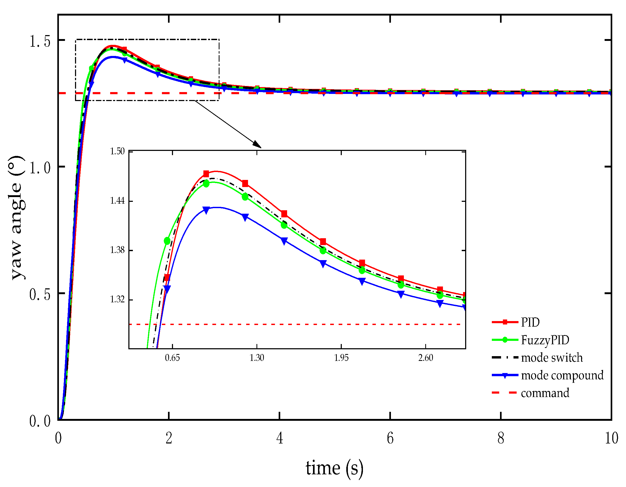
Figure 10.
Test curve of yaw angle response in the attitude adjustment phase.
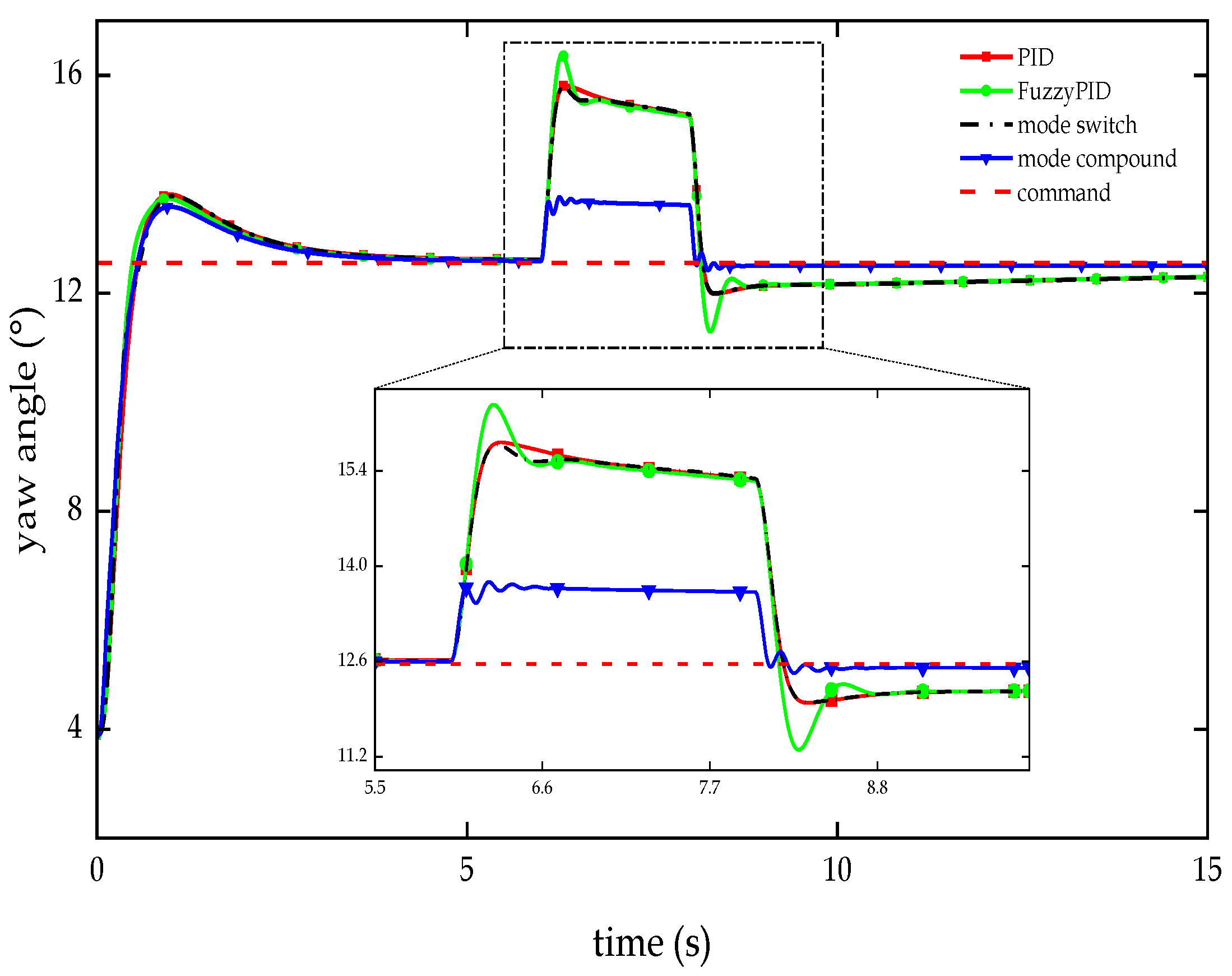
Figure 10.
Test curve of yaw angle response in the attitude adjustment phase.
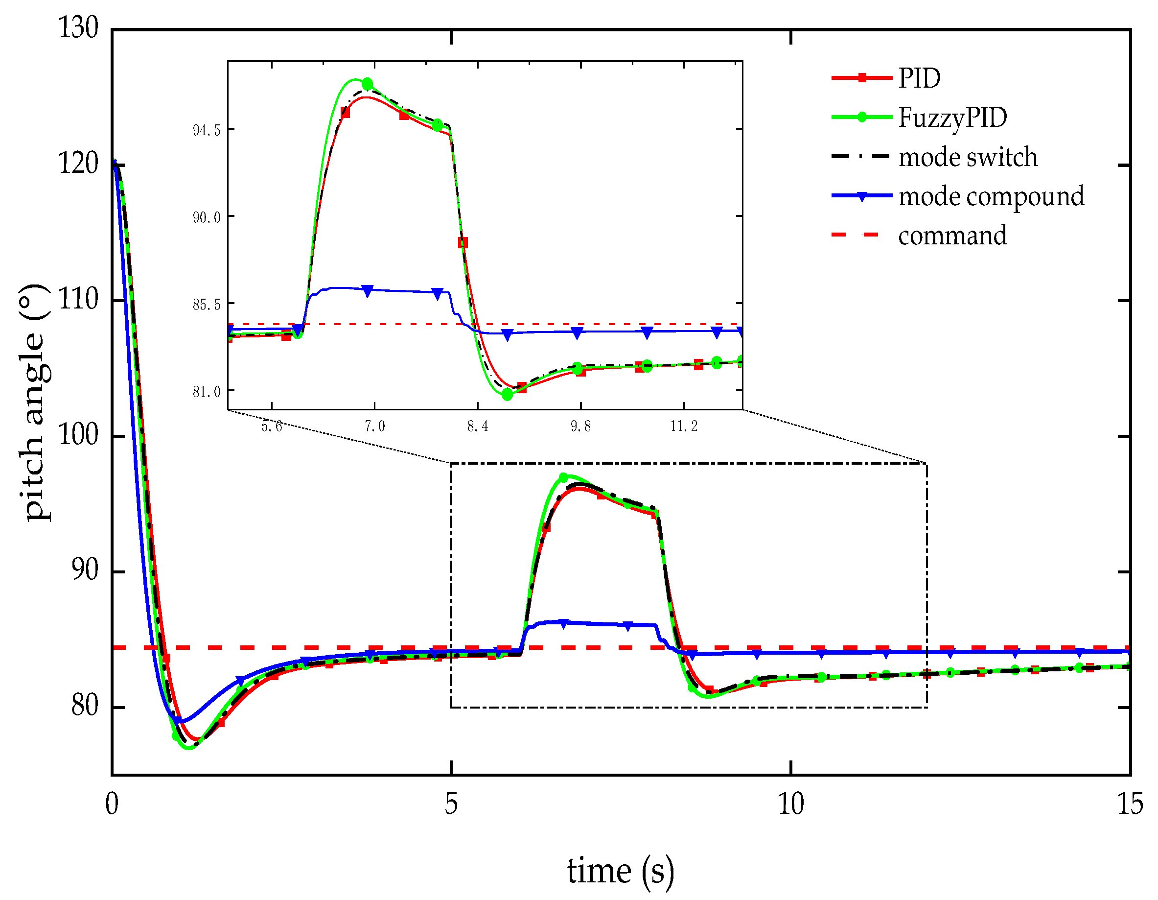
Figure 11.
Test curve of anti-interference in the pitch angle channel.
Figure 11.
Test curve of anti-interference in the pitch angle channel.
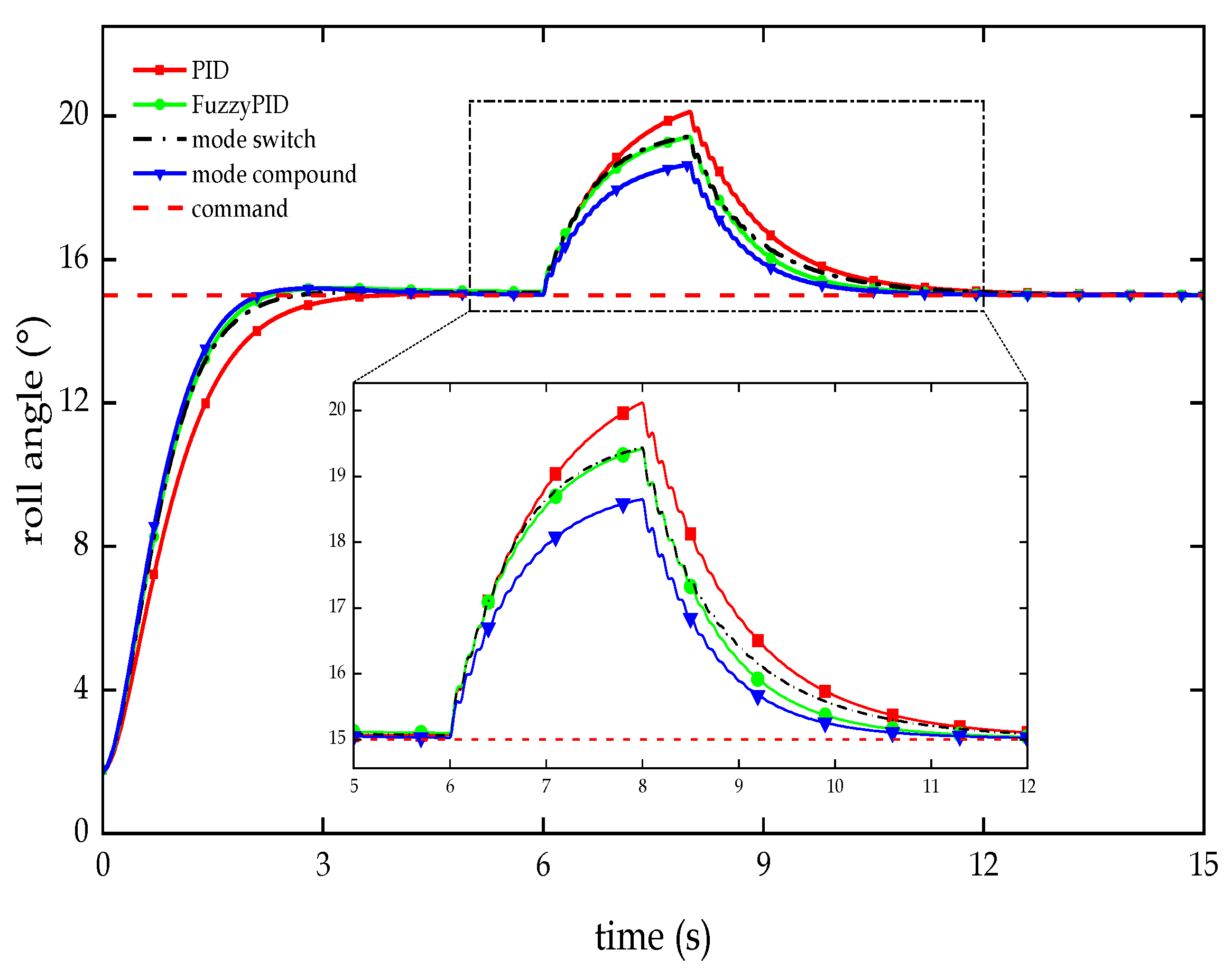
Figure 12.
Test curve of anti-interference in the roll angle channel.
Figure 12.
Test curve of anti-interference in the roll angle channel.
Figure 13.
Test curve of anti-interference in the yaw angle channel.
Figure 13.
Test curve of anti-interference in the yaw angle channel.
Table 1.
Step tracking test indicators for pitch angle channel.
Table 1.
Step tracking test indicators for pitch angle channel.
| Controllers |
Overshoot (%) |
Adjusting time (s) |
Steady-state error (°) |
| PID |
9.739 |
2.855 |
2.675 |
| Fuzzy PID |
9.414 |
2.382 |
2.922 |
| Dual-mode switch |
8.999 |
2.408 |
2.869 |
| Dual-mode compound |
8.540 |
1.835 |
2.088 |
Table 2.
Step tracking test indicators for roll angle channel.
Table 2.
Step tracking test indicators for roll angle channel.
| Controllers |
Overshoot (%) |
Adjusting time (s) |
Steady-state error (°) |
| PID |
0.000 |
3.075 |
0.019 |
| Fuzzy PID |
3.359 |
2.081 |
0.024 |
| Dual-mode switch |
2.094 |
2.241 |
0.017 |
| Dual-mode compound |
0.000 |
2.012 |
0.013 |
Table 3.
Step tracking test indicators for yaw angle channel.
Table 3.
Step tracking test indicators for yaw angle channel.
| Controllers |
Overshoot (%) |
Adjusting time (s) |
Steady-state error (°) |
| PID |
13.889 |
2.331 |
0.004 |
| Fuzzy PID |
13.053 |
2.140 |
0.006 |
| Dual-mode switch |
13.305 |
2.182 |
0.005 |
| Dual-mode compound |
11.069 |
1.948 |
0.000 |
Table 4.
Anti-interference test indicators for pitch angle channel.
Table 4.
Anti-interference test indicators for pitch angle channel.
| Controllers |
Maximum deviation value (°) |
Recovery time (s) |
Tracking deviation (°) |
| PID |
11.716 |
1.213 |
1.398 |
| Fuzzy PID |
12.628 |
1.134 |
1.373 |
| Dual-mode switch |
12.063 |
1.143 |
1.412 |
| Dual-mode compound |
1.880 |
0.256 |
0.281 |
Table 5.
Anti-interference test indicators for roll angle channel.
Table 5.
Anti-interference test indicators for roll angle channel.
| Controllers |
Maximum deviation value (°) |
Recovery time (s) |
Tracking deviation (°) |
| PID |
5.118 |
2.815 |
0.011 |
| Fuzzy PID |
4.414 |
2.067 |
0.004 |
| Dual-mode switch |
4.432 |
2.594 |
0.006 |
| Dual-mode compound |
3.649 |
1.771 |
0.002 |
Table 6.
Anti-interference test indicators for yaw angle channel.
Table 6.
Anti-interference test indicators for yaw angle channel.
| Controllers |
Maximum deviation value (°) |
Recovery time (s) |
Tracking deviation (°) |
| PID |
3.254 |
0.613 |
0.262 |
| Fuzzy PID |
3.809 |
0.461 |
0.260 |
| Dual-mode switch |
3.226 |
0.597 |
0.265 |
| Dual-mode compound |
1.205 |
0.210 |
0.051 |
